EP2215850B1 - Method and device for the autostereoscopic display of image data - Google Patents
Method and device for the autostereoscopic display of image data Download PDFInfo
- Publication number
- EP2215850B1 EP2215850B1 EP08848944.8A EP08848944A EP2215850B1 EP 2215850 B1 EP2215850 B1 EP 2215850B1 EP 08848944 A EP08848944 A EP 08848944A EP 2215850 B1 EP2215850 B1 EP 2215850B1
- Authority
- EP
- European Patent Office
- Prior art keywords
- intensity
- subpixels
- image
- head position
- image points
- Prior art date
- Legal status (The legal status is an assumption and is not a legal conclusion. Google has not performed a legal analysis and makes no representation as to the accuracy of the status listed.)
- Not-in-force
Links
Images
Classifications
-
- H—ELECTRICITY
- H04—ELECTRIC COMMUNICATION TECHNIQUE
- H04N—PICTORIAL COMMUNICATION, e.g. TELEVISION
- H04N13/00—Stereoscopic video systems; Multi-view video systems; Details thereof
- H04N13/30—Image reproducers
- H04N13/366—Image reproducers using viewer tracking
- H04N13/376—Image reproducers using viewer tracking for tracking left-right translational head movements, i.e. lateral movements
-
- G—PHYSICS
- G02—OPTICS
- G02B—OPTICAL ELEMENTS, SYSTEMS OR APPARATUS
- G02B30/00—Optical systems or apparatus for producing three-dimensional [3D] effects, e.g. stereoscopic images
- G02B30/20—Optical systems or apparatus for producing three-dimensional [3D] effects, e.g. stereoscopic images by providing first and second parallax images to an observer's left and right eyes
- G02B30/26—Optical systems or apparatus for producing three-dimensional [3D] effects, e.g. stereoscopic images by providing first and second parallax images to an observer's left and right eyes of the autostereoscopic type
- G02B30/27—Optical systems or apparatus for producing three-dimensional [3D] effects, e.g. stereoscopic images by providing first and second parallax images to an observer's left and right eyes of the autostereoscopic type involving lenticular arrays
-
- G—PHYSICS
- G02—OPTICS
- G02B—OPTICAL ELEMENTS, SYSTEMS OR APPARATUS
- G02B30/00—Optical systems or apparatus for producing three-dimensional [3D] effects, e.g. stereoscopic images
- G02B30/20—Optical systems or apparatus for producing three-dimensional [3D] effects, e.g. stereoscopic images by providing first and second parallax images to an observer's left and right eyes
- G02B30/26—Optical systems or apparatus for producing three-dimensional [3D] effects, e.g. stereoscopic images by providing first and second parallax images to an observer's left and right eyes of the autostereoscopic type
- G02B30/30—Optical systems or apparatus for producing three-dimensional [3D] effects, e.g. stereoscopic images by providing first and second parallax images to an observer's left and right eyes of the autostereoscopic type involving parallax barriers
-
- H—ELECTRICITY
- H04—ELECTRIC COMMUNICATION TECHNIQUE
- H04N—PICTORIAL COMMUNICATION, e.g. TELEVISION
- H04N13/00—Stereoscopic video systems; Multi-view video systems; Details thereof
- H04N13/30—Image reproducers
- H04N13/302—Image reproducers for viewing without the aid of special glasses, i.e. using autostereoscopic displays
- H04N13/31—Image reproducers for viewing without the aid of special glasses, i.e. using autostereoscopic displays using parallax barriers
- H04N13/315—Image reproducers for viewing without the aid of special glasses, i.e. using autostereoscopic displays using parallax barriers the parallax barriers being time-variant
-
- H—ELECTRICITY
- H04—ELECTRIC COMMUNICATION TECHNIQUE
- H04N—PICTORIAL COMMUNICATION, e.g. TELEVISION
- H04N13/00—Stereoscopic video systems; Multi-view video systems; Details thereof
- H04N13/30—Image reproducers
- H04N13/366—Image reproducers using viewer tracking
- H04N13/371—Image reproducers using viewer tracking for tracking viewers with different interocular distances; for tracking rotational head movements around the vertical axis
-
- H—ELECTRICITY
- H04—ELECTRIC COMMUNICATION TECHNIQUE
- H04N—PICTORIAL COMMUNICATION, e.g. TELEVISION
- H04N13/00—Stereoscopic video systems; Multi-view video systems; Details thereof
- H04N13/30—Image reproducers
- H04N13/366—Image reproducers using viewer tracking
- H04N13/373—Image reproducers using viewer tracking for tracking forward-backward translational head movements, i.e. longitudinal movements
Definitions
- the invention relates to a method for autostereoscopic display of image information on a matrix screen according to the preamble of the main claim and to a corresponding device for autostereoscopic presentation of image information according to the preamble of the independent claim.
- a multiplicity of picture elements are formed on the matrix screen by a respective subpixel group having a plurality of intensity-variable subpixels arranged in rows and columns, wherein two stereoscopic fields are respectively imaged on one of two subgroups of the pixels and wherein the two subsets of pixels outgoing light is passed through a barrier grid in two adjacent viewing zones, that of the Pixels of a first of the two subgroups outgoing light into a left viewing zone for a left eye and the light emanating from the pixels of a second of the two subgroups falls into a right viewing zone for a right eye of a viewer.
- a change of a head position of the observer is further detected and a control of the subpixels adapted to the change of the head position.
- This is intended to ensure that stereoscopic vision of the image information, for which each of the two fields must be seen by exactly one of the two eyes, is possible at different head positions and is also maintained during a head movement.
- a corresponding prior art is in the document WO 98/27451 A1 shown. However, the method described there is only suitable for tracking a lateral head movement of the observer.
- the present invention is therefore based on the object of proposing a method for the autostereoscopic display of image information, with which an adaptation within a larger range of motion of the viewer is possible, and this adjustment should also be made without noticeable to the viewer jumps.
- the invention is further based on the object to develop a corresponding device for the autostereoscopic display of image information, which allows a more flexible adaptation to a changing head position of the viewer.
- a flexible adaptation of the image representation also to a change of viewing distance between the observer's head position and matrix screen is made possible by the subpixels within each of the pixels being driven with an intensity weighted subpixel-dependent in addition to the image information in such a way that an intensity centroid within the respective focal point and thus a center of gravity of a lateral intensity distribution of the light emanating from this pixel is laterally displaceable in the corresponding viewing zone, wherein the intensity centers within the pixels are shifted by changing the viewing distance by adjusting the weighting of the intensities so that a lateral distance between the focus of the intensity distributions in the left viewing zone and the center of gravity of the intensity distributions in the right viewing zone into one r remains constant with the head position changing viewing plane.
- a lateral distance between the intensity centroid within a pixel of the first subgroup and the intensity centroid within a nearest pixel corresponding to the respective pixel of the first subgroup of the second subgroup can be changed.
- the barrier grid is located between the matrix screen and the viewer, this is conveniently done by decreasing said distance at a magnification the viewing distance and by increasing said distance in a reduction of the viewing distance.
- the head position of the observer can be detected directly or indirectly, wherein the head position does not necessarily have to be determined with respect to all degrees of freedom.
- the intensities of the subpixels of all pixels are weighted such that within the viewing plane detected with the head position, the focal points of the intensity distributions of the light emanating from the different pixels of the first subgroup in the left viewing zone coincide and the focal points of the intensity distributions of the from the different pixels of the second subset of outgoing light in the right viewing zone are coincident.
- This corresponds to driving the matrix screen optimized for a head position where the observer's left eye in the viewing plane is at the common centroid of the intensity distributions of the light emanating from the pixels of the first subgroup and the right eye of the viewer in the common centroid of the intensity distributions of the light emanating from the pixels of the second subgroup in the right viewing zone.
- intensity center or center of gravity of an intensity is to be understood in each case as the location which is integrated by integrating the spatial coordinates weighted with the respective radiation power or radiation intensity over a (finally extended) pixel or over the viewing plane or the part of the viewing plane falling into the corresponding viewing zone results.
- Stereoscopic fields in the sense of the present specification are any images that are perceptible together with another field of a pair of fields as a three-dimensional stereo image.
- a plurality of stereo images which in each case consist of two stereoscopic fields in the manner described, can also be represented in succession using the method described here, for example for the reproduction of a 3D film.
- the intensity centers within the pixels can be displaced laterally in a lateral change of the head position by adjusting the weighting of the intensities in proportion to this change.
- An advantageous device for the autostereoscopic display of image information which is set up by the program in order to carry out the described method, thus comprises a matrix screen with a plurality of arranged in rows and columns, in intensity variable subpixels, which are combined into a plurality of subpixel groups for reproducing one pixel, a parallel to the matrix screen arranged barrier grid, with the light emanating from the pixels in each one of two neighboring viewing zones, a device for detecting the head position of a viewer and a control device for driving the subpixels of the matrix screen.
- This device can be suitably executed in particular by appropriate programming of the control device for a method of a proposed type.
- the barrier grid may include, for example, grid lines, prism elements or cylindrical lenses running parallel to a column direction of the matrix screen, wherein the column direction may run perpendicular to the line direction or also obliquely thereto.
- the driving of the subpixels within each of the subpixel-dependent weighted intensity pixels can be realized by multiplying an intensity value for one pixel resulting from the image information for each subpixel of the pixel by a value of a weighting function, this weighting function being derived from the Image information is independent, has a shape dependent on the head position and a location of the pixel, and defines for each subpixel of the pixel a location-dependent weight within each row.
- the dependence of these weighting functions on the head position can be designed so that within the pixels - given the image information - a radiation power remains constant at the laterally shifting point of the intensity center of gravity, so that a brightness impression, which the viewer perceives, does not change with the change in the head position despite possible shadowing of edge areas of the picture elements.
- the weighting functions may also be expedient to design the weighting functions in such a way that a total radiation power of the subpixels of a pixel remains constant while the image information remains the same but the viewer's head position changes.
- the locations of the intensity centroids typically coincide with a maximum of the corresponding weighting function.
- maxima or the intensities of intensity within the individual pixels are to lie at a given head position and a given eye distance, the skilled person will easily and unambiguously derive geometric parameters of the apparatus used, namely apart from the eye distance and the viewing distance, in particular from one period length of the barrier grid and a distance between the matrix screen and the barrier grid.
- the lateral distance between the center of gravity of the intensity distributions in the left viewing zone and the center of gravity of the intensity distribution in the right viewing zone should be the same at a changing viewing distance and should correspond to the interpupillary distance.
- an average value of - corresponding to a population average - for example, 65 mm can be assumed for the interpupillary distance, because the viewing zones have a finite extent.
- An advantageous development provides that in addition to the head position, a lateral eye relief is determined by the observer and the intensities within the pixels are weighted so that the lateral distance between the centroid of the intensity distributions in the left viewing zone and the centroid of the intensity distributions in the right viewing zone within the viewing plane, ie at a distance corresponding to the viewing distance from the matrix screen or from the barrier grid corresponding to the determined eye distance.
- the device used may additionally comprise a device for determining an eye distance of the observer, for example with at least one video camera, which receives a face of the observer, wherein the interpupillary distance can then be determined by evaluating images thus obtained.
- the change of the head position is detected in preferred embodiments of the invention without contact with a tracking method.
- the device for detecting the head position may include at least one video camera, which may also be used at the same time for determining the eye distance, wherein the head position is again determined by evaluating images obtained therewith - if several cameras are used, e.g. with the help of a triangulation method.
- the control of the matrix screen can be carried out in such a way that, in each row of the matrix screen, pixels of the first subgroup alternate with pixels of the second subgroup. Then, an advantageously simple executed static barrier grid can be used.
- the pixels of the two subgroups can also are formed by the same subpixels, which are then time sequentially driven to alternately display pixels of the two stereoscopic fields, the barrier grid being synchronously switched between two states to alternately emit light emanating from the pixels into the left viewing zone for the left eye and in to guide the right viewing zone for the right eye of the viewer.
- each pixel can be formed with at least three rows of subpixels and in each row with at least three subpixels of different color, so that a lateral shifting of the intensity centers is color-neutral possible.
- an order of the colors of the subpixels of each pixel in the row direction within the pixel between the rows is cyclically reversed. This in turn can e.g. be achieved by an oblique arrangement of the columns or by a line by side offset of the subpixels of the same color.
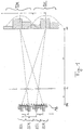
- FIG. 1 The structure of an autostereoscopic display is in FIG. 1 shown.
- the display consists of a matrix screen MB with the pixel plane PE, in front of which separating elements of a barrier grid are arranged in a separating plane TE parallel to the matrix screen MB. These are, for example, periodically spaced apart from each other L slots, prism elements or cylindrical lenses.
- the eyes of the beholder are in a viewing plane BE.
- the distances between pixel level PE, separation level TE and viewing level BE are marked with a and A.
- image columns BSR for the right stereo and BSL for the left stereo view are alternately applied - see also FIG.
- the barrier grid ensures that light emanating from the pixels of the image columns BSR falls into a right viewing zone EZR for a right eye of an observer and light emanating from the pixels of the image columns BSL falls into a left viewing zone BZL for a left eye of the observer.
- the viewing zones BZR and BZL are also referred to herein as stereo zones.
- the image columns run parallel to the optical elements of the barrier grid (lenses, slits), also referred to as the separation grid.
- Brightness focal points or intensities of the image columns of a stereo pair BSR-BSL have the distance p from each other in the pixel plane PE.
- the distance from stereo pair to stereo pair is indicated by q.
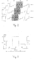
- a section of the pixel field of a panel forming the matrix screen shows the FIG. 2 ,
- the image columns BSR and BSL for the right and left stereo views run diagonally across the panel.
- Nine obliquely arranged, colored, intensity - changeable subpixels - in FIG. 2 marked by R for red, G for green, B for blue - each form one pixel. Viewed from the oblique stereo zones, this arrangement ensures the color purity of the pixels.
- the brightness of each subpixel is multiplied by a weight.
- the passage of these weights over the pixel lines is in FIG. 2 where RELIN stands for relative intensity. This function is the same for all pixel lines, offset by one subpixel only from line to line.
- an orientation of the image columns perpendicular to the lines would also be possible in the case of line-by-line cyclically interchanged or laterally shifted order of the colors of the subpixels.
- other arrangements of subpixels to a pixel In particular, each row of each pixel may also contain four or more than four subpixels.
- monochrome subpixels can alternatively be used.
- a matrix screen with multi-color pixels in which each successively arranged primary color pixels each form a functioning here as a subpixel, tunable by the colors multi-color pixels.
- a further embodiment of the invention provides that an odd number of subpixels - for example, five subpixels - is distributed in a row to one pixel each of both fields. Then, depending on the head position, a central subpixel can be assigned to one or the other field and, under certain conditions, also be mixed with image information of both fields.
- the brightness centers of gravity or intensities of intensity can thus be defined in the pixel plane move the image columns to the left or right.
- the stereo zones in the viewing plane BE move towards it, reinforced by the A / a times. If only the distance q between the image columns is changed, the viewing plane BE moves towards or away from the display.
- an in Fig. 1 set distance P between the stereo channels in the viewer's plane which is defined as the distance between a center of gravity of a resulting intensity distribution in the left viewing plane BZL and a center of gravity of a resulting intensity distribution in the right viewing zone BZR, within the viewing plane BE.
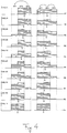
- FIG. 3 shows the course of a weighting of the intensity over a subpixel triple of a width b with three subpixels SP1, SP2 and SP3.
- the weights GW can be changed here only in 2 N discrete stages due to a digital control of the subpixels, so that the center of gravity S can also be moved only gradually.
- a shift to the full width of a subpixel with the greatest possible pixel brightness can be achieved if the total area under the staircase curve is set to 2/3 * b. This corresponds to the area of two subpixels, which can either be completely shifted to the two subpixels SP1 and SP2 or SP2 and SP3.
- the center of gravity then shifts b / 6 in one direction or the other, ie, in total by the width of a subpixel.
- the total area under the staircase - and thus the sacredness and color of the pixel - it remains unchanged: GW 1 + GW 2 + GW 3 constant
- GW1, GW2 and GW3 stand for the weights GW for the three subpixels SP1, SP2 and SP3.
- d GW 3 - GW 1 / GW 1 + GW 2 + GW 3 * b / 3
- FIG. 3 shows an arrangement in which the central subpixel SP2 all 2 N possible area shares are assigned, and the remaining 2 N are distributed to the two subpixels SP1 and SP3. With symmetrical weight distribution, the two outer subpixels each have 2 N-1 area shares.
- M can assume the values 0 ⁇ M ⁇ 2 N-1 .
- the smallest step size in this case is b / (3 * 2 N ).
- the last-mentioned step size also results if a surface element is removed or added to one of the outer subpixels SP1 or SP3.
- the area under the staircase differs only by a surface element from the 'target value' 2/3 * b.
- the associated variation in pixel brightness is virtually imperceptible to the viewer.
- P 65 mm
- Table shows, in particular for a series of viewing distances A, the associated distances q of the centers of gravity: A .DELTA.A q .DELTA.Q P .DELTA.P p Ap Ap / .DELTA.Q [Mm] [Mm] [Mm] [Mm] [Mm] [Mm] [Mm] [Mm] 450 -150 0.528712 0.0007 49 -16 .3520 0.088 123.6 475 -125 0.528562 0.0006 51 -14 .3335 0,069 123.6 500 -100 0.528427 0.0004 54 -11 .3168 0.053 123.6 525 -75 0.528305 0.0003 57 -8th .3017 0,038 123.6 550 -50 0.528194 0.0002 60 -5 .2880 0.024 123.6 575 -25 0.528093 0.0001 62 -3 .2755 0.011 123.6 600 0
- the viewing plane BE should be able to be tracked in increments of approximately 25 mm to 50 mm, which according to Table 1 requires a computational accuracy for q of
- ⁇ 0.0001 mm / 2 0.00005 mm. But that does not mean that this tight tolerance is required for the location of the image strips. This will be explained below: Due to the oblique pattern of the image columns in the pixel plane PE run a horizontal line. The meeting point of this line with the center of gravity of the first left image column now forms the reference point from which the distances of all other image columns to the right of it are measured.
- the stereo channels can be adjusted in the entire distance range of the eye distance, as long as it is less than 65 mm. For larger eye distances, the adjustment is difficult only at close range.
- a change in the head position of the observer is detected, in the preferred embodiment contactless with a tracking method using at least one video camera for observing the head position, wherein the driving of the subpixels to the detected change of the head position during a movement of the head Viewer is adjusted.
- the subpixels within each of the pixels with one in addition to the image information of the two stereo images line by line Controlled subpixel-dependent weighted intensity, so that by changing the weighting in the manner described the intensity center of gravity within the respective pixel and thus the center of gravity of the lateral intensity distribution of the light emanating from this pixel in the corresponding viewing zone BZR or BZL is laterally displaceable.
- the main emphases in the FIGS. 3 and 4 are denoted by S and are obtained by summing the weighted with the respective local coordinates of the subpixels of the corresponding pixel, are thereby within the pixels in a change in the viewing distance A, so the distance between the head position and matrix screen MB, by adjusting the weight of Intensities so that the lateral distance P between the centroid of the intensity distribution in the left viewing zone BZL and the centroid of the intensity distribution in the right viewing zone BZR remains constant within the viewing plane BE changing with the head position.
- the distance P should not deviate from the nominal value 65 mm by more than 3 mm.
- the intensities of the subpixels of all pixels in the matrix screen MB off Fig. 1 are weighted in such a way that the centers of gravity of the respective intensity distributions within the viewing plane BE in the viewing zones BZR and BZL are all in coincidence.
- the centers of intensities within the pixels for tracking are shifted laterally in proportion to a lateral change in head position, so that the centroids the intensities in the viewing zones BZR and BZL always coincide at least approximately with the positions of the two eyes of the observer.
- a lateral eye distance of the observer is determined, preferably with the video cameras, which are also used for detecting the head position.
- the intensities within the pixels are then weighted such that the lateral distance P between the centroid of the intensity distributions in the left viewing zone BZL and the centroid of the intensity distributions in the right viewing zone BZR within the viewing plane BE corresponds to the determined eye distance.
- the subpixels of the matrix screen MB are controlled to autostereoscopically display the image information to be perceived three-dimensionally by the viewer by multiplying, within each of the pixels, an intensity value resulting from the image information for each subpixel of the respective pixel with the corresponding weight GW the weights GW as values in the FIGS. 2 to 4 illustrated weighting function are interpretable for each pixel and wherein these weighting functions are independent of the image information and have a shape dependent on the head position and a location of the pixel.
- Another embodiment of the invention which is an alternative to the Fig. 1 described device provides that the barrier grid synchronized with the subpixels of the matrix screen MB is switchable between two states, to guide light emanating from the pixels alternately in the left viewing zone BZL and the right viewing zone BZR. Then, the pixels of the stereo image for the left eye and the pixels of the stereo image for the right eye - unlike the above-described embodiment - formed by the same subpixels, which are time-sequentially driven thereto, in synchronism with a switching of Barrier raster between the two states.
- a method which ensures a smooth, continuous electronic image tracking without perceptible Umschalt bine in all head movements of the viewer in parallel and at a distance from the matrix screen MB with consistently high imaging quality in terms of image resolution, channel crosstalk or other interference effects.
- This method has the advantage of adjusting the distance between the effective centers of gravity, ie the locations of highest radiation intensity, in the viewing zones BZL and BZR for the left and right observer eye to the eye distance of the observer and to keep constant with changes in the observer distance.
- the method can be implemented in a simple manner by a corresponding programming of a control device which activates the matrix screen MB.
- the method is simple and inexpensive to implement, where it can advantageously work in real time and is resistant to interference.
- a tracking is thus realized in autostereoscopic displays, in which the viewer retains a stereoscopic image impression even when changing position.
- the method described here enlarges the area in which the stereo image can be perceived in good quality. It is particularly advantageous in preferred embodiments of the invention that persons with different eye distances can equally well perceive the stereoscopic effect.
- the invention can be used advantageously for many different applications, for example in the context of gaming, minimally invasive surgery, multimedia, VR, advertising, remote control systems and educational applications, for example in museums.
- the device proposed by the present specification comprises a matrix screen MB having a plurality of intensity-variable subpixels arranged in rows and columns, which are combined into a plurality of subpixel groups for reproducing one pixel at a time.
- a barrier grid arranged parallel to the matrix screen MB, with which the light emanating from the pixels can be guided into in each case one of two adjacent viewing zones BZL and BZR, as well as a device for detecting a head position of a viewer and a control device for driving the subpixels of the matrix screen MB.
- the pixels are in each case assigned to one of two subgroups, these subgroups being defined by the light emanating from the pixels of one subgroup passing through the barrier grid into the left viewing zone BZL for a left viewer eye and the light emanating from the pixels of the other subgroup through the barrier grid into the right viewing zone BZR for a right viewer eye.
- the intensity with which an arbitrary subpixel is controlled is then obtained by multiplying an intensity resulting from the image information for the pixel to which this subpixel is assigned by a value of the weighting function assigned to this pixel.
- the weighting functions are now modified in such a way that the intensity centers S shift laterally within a pixel. Such an adaptation is carried out, in particular, when the viewing distance A is changed, such that a distance p between the intensity centroid S of a pixel radiating into the viewing zone BZL and the intensity centroid S of the corresponding pixel radiating into the other viewing zone BZR changes.
- the distance p is changed so that the lateral distance P between the center of gravity of the intensity distribution caused by the former pixel in the left viewing zone BZL and the center of gravity of the intensity distribution caused by the second pixel in the right viewing zone BZR is changed in which the viewing distance A is remote from the matrix screen MB (eg from the pixel plane PE or from the barrier grid) and remains constant with A changing viewing plane BE.
- the value of p has to be changed for this, results from simple trigonometric calculations, as the person skilled in the art can easily recognize from the geometric contexts, eg in Fig. 1 are shown.
Description
Die Erfindung betrifft ein Verfahren zum autostereoskopischen Darstellen von Bildinformationen auf einem Matrixbildschirm nach dem Oberbegriff des Hauptanspruchs sowie eine entsprechende Vorrichtung zum autostereoskopischen Darstellen von Bildinformationen nach dem Oberbegriff des Nebenanspruchs.The invention relates to a method for autostereoscopic display of image information on a matrix screen according to the preamble of the main claim and to a corresponding device for autostereoscopic presentation of image information according to the preamble of the independent claim.
Bei einem gattungsgemäßen Verfahren wird auf dem Matrixbildschirm eine Vielzahl von Bildpunkten durch jeweils eine Subpixelgruppe mit einer Mehrzahl von in ihrer Intensität veränderbaren, in Zeilen und Spalten angeordneten Subpixeln gebildet, wobei zwei stereoskopische Halbbilder auf jeweils einer von zwei Untergruppen der Bildpunkte abgebildet werden und wobei von den zwei Untergruppen von Bildpunkten ausgehendes Licht durch ein Barrierenraster so in zwei benachbarte Betrachtungszonen geleitet wird, dass das von den Bildpunkten einer ersten der beiden Untergruppen ausgehende Licht in eine linke Betrachtungszone für ein linkes Auge und das von den Bildpunkten einer zweiten der beiden Untergruppen ausgehende Licht in eine rechte Betrachtungszone für ein rechtes Auge eines Betrachters fällt. Dabei wird ferner eine Änderung einer Kopfposition des Betrachters detektiert und eine Ansteuerung der Subpixel an die Änderung der Kopfposition angepasst. Dadurch soll erreicht werden, dass ein stereoskopisches Sehen der Bildinformationen, für das jedes der zwei Halbbilder von genau einem der beiden Augen gesehen werden muss, bei verschiedenen Kopfpositionen möglich ist und auch bei einer Kopfbewegung erhalten bleibt. Ein entsprechender Stand der Technik ist in der Druckschrift
Der vorliegenden Erfindung liegt also die Aufgabe zugrunde, ein Verfahren zum autostereoskopischen Darstellen von Bildinformationen vorzuschlagen, mit dem eine Anpassung innerhalb eines größeren Bewegungsspielraums des Betrachters möglich wird, wobei diese Anpassung darüber hinaus ohne für den Betrachter wahrnehmbare Sprünge erfolgen soll. Der Erfindung liegt ferner die Aufgabe zugrunde, eine entsprechende Vorrichtung zum autostereoskopischen Darstellen von Bildinformationen zu entwickeln, die eine flexiblere Anpassung an eine sich ändernde Kopfposition des Betrachters erlaubt.The present invention is therefore based on the object of proposing a method for the autostereoscopic display of image information, with which an adaptation within a larger range of motion of the viewer is possible, and this adjustment should also be made without noticeable to the viewer jumps. The invention is further based on the object to develop a corresponding device for the autostereoscopic display of image information, which allows a more flexible adaptation to a changing head position of the viewer.
Diese Aufgabe wird erfindungsgemäß gelöst durch ein Verfahren mit den kennzeichnenden Merkmalen des Hauptanspruchs in Verbindung mit den Merkmalen des Oberbegriffs des Hauptanspruchs sowie durch eine Vorrichtung mit den Merkmalen des Nebenanspruchs. Vorteilhafte Ausgestaltungen und Weiterentwicklungen der Erfindung ergeben sich mit den Merkmalen der Unteransprüche.This object is achieved by a method with the characterizing features of the main claim in conjunction with the features of the preamble of the main claim and by a device with the characteristics of the secondary claim. Advantageous embodiments and further developments of the invention will become apparent with the features of the subclaims.
Mit der Erfindung wird eine flexible Anpassung der Bilddarstellung auch an eine Änderung einer Betrachtungsentfernung zwischen Kopfposition des Betrachters und Matrixbildschirm dadurch möglich, dass die Subpixel innerhalb jedes der Bildpunkte mit einer zusätzlich zu den Bildinformationen zeilenweise subpixelabhängig gewichteten Intensität angesteuert werden derart, dass ein Intensitätsschwerpunkt innerhalb des jeweiligen Bildpunkts und damit ein Schwerpunkt einer seitlichen Intensitätsverteilung des von diesem Bildpunkt ausgehenden Lichts in der entsprechenden Betrachtungszone seitlich verschiebbar ist, wobei die Intensitätsschwerpunkte innerhalb der Bildpunkte bei einer Änderung der Betrachtungsentfernung durch ein Anpassen der Gewichtung der Intensitäten so verschoben werden, dass ein seitlicher Abstand zwischen dem Schwerpunkt der Intensitätsverteilungen in der linken Betrachtungszone und dem Schwerpunkt der Intensitätsverteilungen in der rechten Betrachtungszone in einer sich mit der Kopfposition verändernden Betrachtungsebene konstant bleibt. Zur Anpassung an die Änderung der Betrachtungsentfernung kann dabei jeweils ein seitlicher Abstand zwischen dem Intensitätsschwerpunkt innerhalb eines Bildpunkts der ersten Untergruppe und dem Intensitätsschwerpunkt innerhalb eines nächstgelegenen, dem jeweiligen Bildpunkt der ersten Untergruppe entsprechenden Bildpunkts der zweiten Untergruppe verändert werden. Wenn das Barrierenraster zwischen dem Matrixbildschirm und dem Betrachter angeordnet ist, geschieht das zweckmäßigerweise durch ein Verringern des genannten Abstands bei einer Vergrößerung der Betrachtungsentfernung und durch ein Vergrößern des genannten Abstandes bei einem Verkleinern der Betrachtungsentfernung. Zum Bestimmen der sich ändernden Betrachtungsentfernung kann die Kopfposition des Betrachters dabei direkt oder indirekt detektiert werden, wobei die Kopfposition nicht notwendigerweise bezüglich aller Freiheitsgrade bestimmt werden muss.With the invention, a flexible adaptation of the image representation also to a change of viewing distance between the observer's head position and matrix screen is made possible by the subpixels within each of the pixels being driven with an intensity weighted subpixel-dependent in addition to the image information in such a way that an intensity centroid within the respective focal point and thus a center of gravity of a lateral intensity distribution of the light emanating from this pixel is laterally displaceable in the corresponding viewing zone, wherein the intensity centers within the pixels are shifted by changing the viewing distance by adjusting the weighting of the intensities so that a lateral distance between the focus of the intensity distributions in the left viewing zone and the center of gravity of the intensity distributions in the right viewing zone into one r remains constant with the head position changing viewing plane. To adapt to the change of the viewing distance, in each case a lateral distance between the intensity centroid within a pixel of the first subgroup and the intensity centroid within a nearest pixel corresponding to the respective pixel of the first subgroup of the second subgroup can be changed. When the barrier grid is located between the matrix screen and the viewer, this is conveniently done by decreasing said distance at a magnification the viewing distance and by increasing said distance in a reduction of the viewing distance. To determine the changing viewing distance, the head position of the observer can be detected directly or indirectly, wherein the head position does not necessarily have to be determined with respect to all degrees of freedom.
Bei einer bevorzugten Ausführung der Erfindung werden die Intensitäten der Subpixel aller Bildpunkte so gewichtet, dass innerhalb der mit der Kopfposition detektierten Betrachtungsebene die Schwerpunkte der Intensitätsverteilungen des von den verschiedenen Bildpunkten der ersten Untergruppe ausgehenden Lichts in der linken Betrachtungszone aufeinander fallen und die Schwerpunkte der Intensitätsverteilungen des von den verschiedenen Bildpunkten der zweiten Untergruppe ausgehenden Lichts in der rechten Betrachtungszone aufeinander fallen. Das entspricht einer Ansteuerung des Matrixbildschirms, die optimiert ist für eine Kopfposition, bei der das linke Auge des Betrachters in der Betrachtungsebene im gemeinsamen Schwerpunkt der Intensitätsverteilungen des von den Bildpunkten der ersten Untergruppe ausgehenden Lichts liegt und das rechte Auge des Betrachters im gemeinsamen Schwerpunkt der Intensitätsverteilungen des von den Bildpunkten der zweiten Untergruppe ausgehenden Lichts in der rechten Betrachtungszone.In a preferred embodiment of the invention, the intensities of the subpixels of all pixels are weighted such that within the viewing plane detected with the head position, the focal points of the intensity distributions of the light emanating from the different pixels of the first subgroup in the left viewing zone coincide and the focal points of the intensity distributions of the from the different pixels of the second subset of outgoing light in the right viewing zone are coincident. This corresponds to driving the matrix screen optimized for a head position where the observer's left eye in the viewing plane is at the common centroid of the intensity distributions of the light emanating from the pixels of the first subgroup and the right eye of the viewer in the common centroid of the intensity distributions of the light emanating from the pixels of the second subgroup in the right viewing zone.
In dieser Schrift seien dabei verschiedene Schwerpunkte von Intensitäten, die geringfügig, aber vorzugsweise nicht mehr als 5 mm, besonders vorzugsweise nicht mehr als 3 mm seitlich voneinander entfernt liegen, noch als aufeinander fallend bezeichnet. Ein Nachführen der Darstellung bei sich ändernder Betrachtungsentfernung in beschriebener Art soll bei bevorzugten Ausführungen der Erfindung über einen mindestens 30 cm tiefen Bereich verschiedener Betrachtungsentfernungen möglich sein, damit eine hinreichende Unempfindlichkeit gegenüber Kopfbewegungen erreicht wird. Der Begriff Intensitätsschwerpunkt oder Schwerpunkt einer Intensität sei jeweils verstanden als der Ort, der sich durch Integrieren der mit der jeweiligen Strahlungsleistung bzw. Strahlungsintensität gewichteten Ortskoordinaten über einen (endlich ausgedehnten) Bildpunkt bzw. über die Betrachtungsebene oder den in die entsprechende Betrachtungszone fallenden Teil der Betrachtungsebene ergibt. Stereoskopische Halbbilder im Sinne der vorliegenden Schrift seien beliebige Bilder, die jeweils zusammen mit einem anderen Halbbild eines Paares von Halbbildern als dreidimensionales Stereobild wahrnehmbar sind. Mit dem hier beschriebenen Verfahren kann dabei selbstverständlich auch eine Mehrzahl von Stereobildern, die sich jeweils in beschriebener Weise aus zwei stereoskopischen Halbbildern zusammensetzen, in Folge dargestellt werden, beispielsweise zur Wiedergabe eines 3D-Films.In this document, different emphases of intensities which are slightly, but preferably not more than 5 mm, particularly preferably not more than 3 mm laterally apart, are still referred to as falling on one another. Tracking the display as the viewing distance changes in the manner described should be possible in preferred embodiments of the invention over a range of at least 30 cm deep different viewing distances, so that a sufficient insensitivity to head movements is achieved. The term intensity center or center of gravity of an intensity is to be understood in each case as the location which is integrated by integrating the spatial coordinates weighted with the respective radiation power or radiation intensity over a (finally extended) pixel or over the viewing plane or the part of the viewing plane falling into the corresponding viewing zone results. Stereoscopic fields in the sense of the present specification are any images that are perceptible together with another field of a pair of fields as a three-dimensional stereo image. Of course, a plurality of stereo images, which in each case consist of two stereoscopic fields in the manner described, can also be represented in succession using the method described here, for example for the reproduction of a 3D film.
Um zusätzlich eine möglichst stetige Nachführung einer seitlichen Bewegung des Betrachters zu gewährleisten, können die Intensitätsschwerpunkte innerhalb der Bildpunkte bei einer seitlichen Änderung der Kopfposition durch ein Anpassen der Gewichtung der Intensitäten proportional zu dieser Änderung seitlich verschoben werden.In addition, in order to ensure as steady a tracking as possible of a lateral movement of the observer, the intensity centers within the pixels can be displaced laterally in a lateral change of the head position by adjusting the weighting of the intensities in proportion to this change.
Eine vorteilhafte Vorrichtung zum autostereoskopischen Darstellen von Bildinformationen, die programmtechnisch zum Durchführen des beschriebenen Verfahrens eingerichtet ist, umfasst also einen Matrixbildschirm mit einer Vielzahl von in Zeilen und Spalten angeordneten, in ihrer Intensität veränderbaren Subpixeln, die in eine Vielzahl von Subpixelgruppen zum Wiedergeben jeweils eines Bildpunkts zusammengefasst sind, ein parallel zu dem Matrixbildschirm angeordnetes Barrierenraster, mit dem von den Bildpunkten ausgehendes Licht in jeweils eine von zwei benachbarten Betrachtungszonen leitbar ist, eine Einrichtung zum Detektieren der Kopfposition eines Betrachters und eine Steuereinrichtung zum Ansteuern der Subpixel des Matrixbildschirms. Diese Vorrichtung kann insbesondere durch entsprechendes Programmieren der Steuereinrichtung für ein Verfahren vorgeschlagener Art geeignet ausgeführt werden. Das Barrierenraster kann, um seine Funktion zu erfüllen, beispielsweise parallel zu einer Spaltenrichtung des Matrixbildschirms verlaufende Gitterlinien, Prismenelemente oder Zylinderlinsen umfassen, wobei die Spaltenrichtung senkrecht zur Zeilenrichtung oder auch schräg dazu verlaufen kann.An advantageous device for the autostereoscopic display of image information, which is set up by the program in order to carry out the described method, thus comprises a matrix screen with a plurality of arranged in rows and columns, in intensity variable subpixels, which are combined into a plurality of subpixel groups for reproducing one pixel, a parallel to the matrix screen arranged barrier grid, with the light emanating from the pixels in each one of two neighboring viewing zones, a device for detecting the head position of a viewer and a control device for driving the subpixels of the matrix screen. This device can be suitably executed in particular by appropriate programming of the control device for a method of a proposed type. To perform its function, the barrier grid may include, for example, grid lines, prism elements or cylindrical lenses running parallel to a column direction of the matrix screen, wherein the column direction may run perpendicular to the line direction or also obliquely thereto.
Das Ansteuern der Subpixel innerhalb jedes der Bildpunkte mit einer subpixelabhängig gewichteten Intensität kann realisiert werden, indem zum Ansteuern der Subpixel ein sich aus den Bildinformationen ergebender Intensitätswert für einen Bildpunkt für jeden Subpixel des Bildpunkts mit einem Wert einer Gewichtungsfunktion multipliziert wird, wobei diese Gewichtungsfunktion von den Bildinformationen unabhängig ist, eine von der Kopfposition und einem Ort des Bildpunkts abhängende Form hat und für jeden Subpixel des Bildpunkts ein innerhalb jeder Zeile ortsabhängiges Gewicht definiert. Die Abhängigkeit dieser Gewichtungsfunktionen von der Kopfposition kann so gestaltet sein, dass innerhalb der Bildpunkte - bei gegebenen Bildinformationen - eine Strahlungsleistung an der sich seitlich verschiebenden Stelle des Intensitätsschwerpunkts konstant bleibt, damit sich ein Helligkeitseindruck, den der Betrachter wahrnimmt, mit der Veränderung der Kopfposition trotz eventueller Abschattungen von Randbereichen der Bildpunkte nicht verändert. Es kann auch zweckmäßig sein, die Gewichtungsfunktionen so zu gestalten, dass eine Gesamtstrahlungsleistung der Subpixel eines Bildpunkts bei gleich bleibenden Bildinformationen, aber sich ändernder Kopfposition des Betrachters konstant bleibt. Die Orte der Intensitätsschwerpunkte fallen typischerweise mit einem Maximum der entsprechenden Gewichtungsfunktion zusammen. Wo diese Maxima bzw. die Intensitätsschwerpunkte innerhalb der einzelnen Bildpunkte bei einer gegebenen Kopfposition und einem gegebenen Augenabstand liegen sollen, ergibt sich für den Fachmann in einfacher und eindeutiger Weise aus geometrischen Parametern der verwendeten Vorrichtung, nämlich neben dem Augenabstand und der Betrachtungsentfernung insbesondere aus einer Periodenlänge des Barrierenrasters und einem Abstand zwischen dem Matrixbildschirm und dem Barrierenraster. Der bei einer sich ändernden Betrachtungsentfernung gleich bleibende seitliche Abstand zwischen dem Schwerpunkt der Intensitätsverteilungen in der linken Betrachtungszone und dem Schwerpunkt der Intensitätsverteilung in der rechten Betrachtungszone, sollte dabei dem Augenabstand entsprechen.The driving of the subpixels within each of the subpixel-dependent weighted intensity pixels can be realized by multiplying an intensity value for one pixel resulting from the image information for each subpixel of the pixel by a value of a weighting function, this weighting function being derived from the Image information is independent, has a shape dependent on the head position and a location of the pixel, and defines for each subpixel of the pixel a location-dependent weight within each row. The dependence of these weighting functions on the head position can be designed so that within the pixels - given the image information - a radiation power remains constant at the laterally shifting point of the intensity center of gravity, so that a brightness impression, which the viewer perceives, does not change with the change in the head position despite possible shadowing of edge areas of the picture elements. It may also be expedient to design the weighting functions in such a way that a total radiation power of the subpixels of a pixel remains constant while the image information remains the same but the viewer's head position changes. The locations of the intensity centroids typically coincide with a maximum of the corresponding weighting function. Where these maxima or the intensities of intensity within the individual pixels are to lie at a given head position and a given eye distance, the skilled person will easily and unambiguously derive geometric parameters of the apparatus used, namely apart from the eye distance and the viewing distance, in particular from one period length of the barrier grid and a distance between the matrix screen and the barrier grid. The lateral distance between the center of gravity of the intensity distributions in the left viewing zone and the center of gravity of the intensity distribution in the right viewing zone should be the same at a changing viewing distance and should correspond to the interpupillary distance.
Bei einer einfachen Ausführung der Erfindung kann für den Augenabstand ein durchschnittlicher Wert von - einem Bevölkerungsdurchschnitt entsprechend - beispielsweise 65 mm angenommen werden, weil die Betrachtungszonen eine endliche Ausdehnung haben. Eine vorteilhafte Weiterentwicklung sieht dagegen vor, dass zusätzlich zur Kopfposition ein seitlicher Augenabstand des Betrachters ermittelt wird und die Intensitäten innerhalb der Bildpunkte so gewichtet werden, dass der seitliche Abstand zwischen dem Schwerpunkt der Intensitätsverteilungen in der linken Betrachtungszone und dem Schwerpunkt der Intensitätsverteilungen in der rechten Betrachtungszone innerhalb der Betrachtungsebene, also in einer der Betrachtungsentfernung entsprechenden Entfernung vom Matrixbildschirm bzw. vom Barrierenraster, dem ermittelten Augenabstand entspricht. Dazu kann die verwendete Vorrichtung zusätzlich eine Einrichtung zum Ermitteln eines Augenabstands des Betrachters umfassen, beispielsweise mit mindestens einer Videokamera, die ein Gesicht des Betrachters aufnimmt, wobei der Augenabstand dann durch Auswerten so gewonnener Bilder ermittelt werden kann.In a simple embodiment of the invention, an average value of - corresponding to a population average - for example, 65 mm can be assumed for the interpupillary distance, because the viewing zones have a finite extent. An advantageous development, however, provides that in addition to the head position, a lateral eye relief is determined by the observer and the intensities within the pixels are weighted so that the lateral distance between the centroid of the intensity distributions in the left viewing zone and the centroid of the intensity distributions in the right viewing zone within the viewing plane, ie at a distance corresponding to the viewing distance from the matrix screen or from the barrier grid corresponding to the determined eye distance. For this purpose, the device used may additionally comprise a device for determining an eye distance of the observer, for example with at least one video camera, which receives a face of the observer, wherein the interpupillary distance can then be determined by evaluating images thus obtained.
Um ein möglichst komfortables Stereosehen zu ermöglichen, wird die Änderung der Kopfposition bei bevorzugten Ausführungen der Erfindung berührungslos mit einem Trackingverfahren detektiert. Dazu kann die Einrichtung zum Detektieren der Kopfposition mindestens eine Videokamera umfassen, die unter Umständen zugleich zum Ermitteln des Augenabstands verwendet wird, wobei die Kopfposition wieder durch ein Auswerten damit gewonnener Bilder ermittelt wird - bei einer Verwendung mehrerer Kameras z.B. mit Hilfe eines Triangulationsverfahrens.In order to allow the most comfortable stereo viewing, the change of the head position is detected in preferred embodiments of the invention without contact with a tracking method. For this purpose, the device for detecting the head position may include at least one video camera, which may also be used at the same time for determining the eye distance, wherein the head position is again determined by evaluating images obtained therewith - if several cameras are used, e.g. with the help of a triangulation method.
Die Ansteuerung des Matrixbildschirms kann so ausgeführt werden, dass sich in jeder Zeile des Matrixbildschirms Bildpunkte der ersten Untergruppe mit Bildpunkten der zweiten Untergruppe abwechseln. Dann kann ein vorteilhaft einfach ausgeführtes statisches Barrierenraster verwendet werden. Alternativ können die Bildpunkte der beiden Untergruppen aber auch durch die selben Subpixel gebildet werden, die dann zeitsequenziell angesteuert werden, um abwechselnd Bildpunkte der beiden stereoskopischen Halbbilder wiederzugeben, wobei das Barrierenraster dazu synchron zwischen zwei Zuständen umgeschaltet wird, um von den Bildpunkten ausgehendes Licht alternierend in die linke Betrachtungszone für das linkes Auge und in die rechte Betrachtungszone für das rechtes Auge des Betrachters zu leiten.The control of the matrix screen can be carried out in such a way that, in each row of the matrix screen, pixels of the first subgroup alternate with pixels of the second subgroup. Then, an advantageously simple executed static barrier grid can be used. Alternatively, the pixels of the two subgroups can also are formed by the same subpixels, which are then time sequentially driven to alternately display pixels of the two stereoscopic fields, the barrier grid being synchronously switched between two states to alternately emit light emanating from the pixels into the left viewing zone for the left eye and in to guide the right viewing zone for the right eye of the viewer.
Eine vorteilhafte Ausführung der Erfindung sieht vor, dass der Matrixbildschirm zum Wiedergeben farbiger Stereobilder geeignet ist. Dazu kann jeder Bildpunkt mit mindestens drei Zeilen von Subpixeln und in jeder Zeile mit mindestens drei Subpixeln verschiedener Farbe gebildet werden, damit ein seitliches Verschieben der Intensitätsschwerpunkte farbneutral möglich wird. Um das sicherzustellen, ist dabei vorzugsweise eine Reihenfolge der Farben der Subpixel jedes Bildpunkts in Zeilenrichtung innerhalb des Bildpunkts zwischen den Zeilen zyklisch vertauscht. Das wiederum kann z.B. durch eine schräge Anordnung der Spalten oder durch einen zeilenweise seitlichen Versatz der Subpixel gleicher Farbe erreicht werden.An advantageous embodiment of the invention provides that the matrix screen is suitable for reproducing colored stereo images. For this purpose, each pixel can be formed with at least three rows of subpixels and in each row with at least three subpixels of different color, so that a lateral shifting of the intensity centers is color-neutral possible. In order to ensure this, preferably an order of the colors of the subpixels of each pixel in the row direction within the pixel between the rows is cyclically reversed. This in turn can e.g. be achieved by an oblique arrangement of the columns or by a line by side offset of the subpixels of the same color.
Ausführungsbeispiele der Erfindung werden nachfolgend anhand der
- Fig. 1
- schematisch in Aufsicht einen Aufbau einer Vorrichtung zum autostereoskopischen Darstellen von Bildinformationen in einer Ausführung der Erfindung,
- Fig. 2
- schematisch einen Ausschnitt aus einem Pixelfeld eines Matrixbildschirms der Vorrichtung aus
Fig. 1 , - Fig. 3
- einen beispielhaften Verlauf einer Gewichtung über drei Subpixel, die eine Zeile eines Bildpunkts auf dem Matrixbildschirm bilden, und
- Fig. 4
- in einer der
Fig. 3 entsprechenden, diagrammatischen Darstellung zwei Beispiele für ein seitliches Verschieben von Intensitätsschwerpunkten innerhalb eines Bildpunkts.
- Fig. 1
- 1 is a schematic plan view of a construction of an apparatus for autostereoscopic display of image information in an embodiment of the invention,
- Fig. 2
- schematically a section of a pixel field of a matrix screen of the device
Fig. 1 . - Fig. 3
- an exemplary course of a weighting over three subpixels, which form a row of a pixel on the matrix screen, and
- Fig. 4
- in one of the
Fig. 3 corresponding diagrammatic representation two examples of a lateral shift of intensity centers within a pixel.
Der Aufbau eines autostereoskopischen Displays ist in
Die Bildspalten verlaufen parallel zu den optischen Elementen des auch als Trennrasters bezeichneten Barriererasters (Linsen, Schlitze). Helligkeits-Schwerpunkte oder Intensitätsschwerpunkte der Bildspalten eines Stereo-Paares BSR-BSL haben in der Pixelebene PE den Abstand p voneinander. Der Abstand von Stereo-Paar zu Stereo-Paar wird durch q gekennzeichnet.The image columns run parallel to the optical elements of the barrier grid (lenses, slits), also referred to as the separation grid. Brightness focal points or intensities of the image columns of a stereo pair BSR-BSL have the distance p from each other in the pixel plane PE. The distance from stereo pair to stereo pair is indicated by q.
Einen Ausschnitt aus dem Pixelfeld eines den Matrixbildschirm bildenden Panels zeigt die
Alternativ wäre auch eine zu den Zeilen senkrechte Orientierung der Bildspalten bei von Zeile zu Zeile zyklisch vertauschter bzw. seitlich verschobener Reihenfolge der Farben der Subpixel möglich. Denkbar sind auch andere Arrangements von Subpixeln zu einem Bildpunkt. Insbesondere können in jeder Zeile jedes Bildpunkts auch vier oder mehr als vier Subpixel enthalten sein. Andererseits können, wenn auf eine Farbwiedergabe verzichtet wird, alternativ monochrome Subpixel verwendet werden. Schließlich ist es auch denkbar, einen Matrixbildschirm mit Vielfarbpixeln einzusetzen, bei dem einzelne hintereinander angeordnete Grundfarbenpixel jeweils einen hier als Subpixel fungierenden, durch die Farben durchstimmbaren Vielfarbpixel bilden. In den zuletzt genannten Fällen kann es genügen, in einem Bildpunkt nur zwei Subpixel in jeder Zeile vorzusehen und/oder einen Bildpunkt nur aus in einer Zeile liegenden Subpixeln zu bilden. Für das Verfahren der Schwerpunktverschiebung sind die Unterschiede zwischen verschiedenen Möglichkeiten der Zusammenfassung von Subpixeln zu einem Bildpunkt aber ohne Belang. Eine weitere Ausgestaltung der Erfindung sieht vor, dass eine ungerade Anzahl von Subpixeln - beispielsweise fünf Subpixel - in einer Zeile auf jeweils einen Bildpunkt beider Halbbilder verteilt wird. Dann kann ein mittiger Subpixel je nach Kopfposition dem einen oder dem anderen Halbbild zugeordnet werden und unter bestimmten Bedingungen auch gemischt mit Bildinformation beider Halbbilder angesteuert werden. Ohnehin ist es denkbar, zusätzlich zu der hier in erster Linie beschriebenen Verschiebung von Intensitätsschwerpunkten innerhalb eines Bildpunkts zur Nachführung der Änderung der Kopfposition auch eine Neuzuordnung von Bildinformation, die jeweils einem der Halbbilder zugeordnet ist, zu Subpixeln vorzunehmen, die durch die - typischerweise seitliche - Änderung jeweils einem anderen Auge des Betrachters sichtbar werden. Einzelne Subpixel können dann im Verlauf einer Änderung der Kopfposition u.U. zunächst einem Bildpunkt des einen und dann einem Bildpunkt des anderen stereoskopischen Halbbilds zugeordnet sein.Alternatively, an orientation of the image columns perpendicular to the lines would also be possible in the case of line-by-line cyclically interchanged or laterally shifted order of the colors of the subpixels. Also conceivable are other arrangements of subpixels to a pixel. In particular, each row of each pixel may also contain four or more than four subpixels. On the other hand, if color reproduction is dispensed with, monochrome subpixels can alternatively be used. Finally it is also conceivable to use a matrix screen with multi-color pixels, in which each successively arranged primary color pixels each form a functioning here as a subpixel, tunable by the colors multi-color pixels. In the latter cases, it may suffice to provide only two subpixels in each pixel in a pixel and / or to form one pixel only from subpixels lying in one row. For the shift of emphasis method, however, the differences between different ways of combining subpixels into a pixel are irrelevant. A further embodiment of the invention provides that an odd number of subpixels - for example, five subpixels - is distributed in a row to one pixel each of both fields. Then, depending on the head position, a central subpixel can be assigned to one or the other field and, under certain conditions, also be mixed with image information of both fields. In any case, in addition to the here described primarily shift of intensity centers within a pixel for tracking the change of the head position, it is also possible to remap image information, which is assigned to one of the fields, to subpixels which are defined by the - typically lateral - Change each visible to another eye of the beholder. Individual subpixels may then, in the course of a change in the head position, be assigned first to a pixel of the one and then to a pixel of the other stereoscopic field.
Durch geeignete Wichtung lassen sich also in der Pixelebene die Helligkeits-Schwerpunkte oder Intensitätsschwerpunkte der Bildspalten nach links oder rechts verschieben. Das hat zur Folge, dass sich die Stereo-Zonen in der Betrachtungsebene BE dem entgegen bewegen, verstärkt um das A/a-fache. Wird lediglich der Abstand q zwischen den Bildspalten verändert, so bewegt sich die Betrachtungsebene BE auf das Display zu oder von ihm weg. Mit dem Abstand p zwischen den Helligkeits-Schwerpunkten lässt sich ein in
Die
Eine Verschiebung um die volle Breite eines Subpixels bei größtmöglicher Pixel-Helligkeit ist dann realisierbar, wenn die Gesamt-Fläche unter der Treppen-Kurve zu 2/3*b gewählt wird. Das entspricht der Fläche zweier Subpixel, die entweder vollständig auf die beiden Subpixel SP1 und SP2 oder SP2 und SP3 verlagert werden kann. Der Schwerpunkt verschiebt sich dann um b/6 in die eine oder in die andere Richtung, also insgesamt um die Breite eines Subpixels. Die Gesamt-Fläche unter dem Treppenzug - und damit die Heiligkeit und Farbe des Pixels - bleibt dabei unverändert: ![]()
![]()
Dabei stehe GW1, GW2 und GW3 für die Gewichte GW für die drei Subpixel SP1, SP2 und SP3. Allgemein gilt für die Verschiebung d des Schwerpunktes aus der hier als Pixel-Mitte bezeichneten Mitte des Bildpunkts in der entsprechenden Zeile: ![]()
![]()
Wegen des Bezugs auf die Pixel-Mitte hat das Gewicht GW2 keinen Einfluss auf die Schwerpunkt-Lage. Die kleinstmögliche Verschiebung hängt davon ab, in welcher Weise die Gewichte umverteilt werden: Die ![]()
![]()
![]()
![]()
![]()
![]()
Dabei kann M die Werte 0≤M≤2N-1 annehmen. Der Schwerpunkt rückt somit um ![]()
![]()
Die Verlagerung des Schwerpunktes bei dieser Vorgehensweise ist auf der linken Seite der ![]()
![]()
Bei der in
Mit großer Näherung ergibt sich die zuletzt genannte Schrittweite auch, wenn bei einem der äußeren Subpixel SP1 oder SP3 ein Flächenelement weggenommen oder hinzugefügt wird. Die Fläche unter dem Treppenzug weicht dabei nur um ein Flächenelement vom 'Sollwert' 2/3*b ab. Bei einer feinen Flächen-Stufung ist die damit einhergehende Schwankung der Pixel-Helligkeit vom Betrachter so gut wie nicht wahrnehmbar.To a large approximation, the last-mentioned step size also results if a surface element is removed or added to one of the outer subpixels SP1 or SP3. The area under the staircase differs only by a surface element from the 'target value' 2/3 * b. With a fine surface gradation, the associated variation in pixel brightness is virtually imperceptible to the viewer.
Noch weiter lässt sich die Schrittweite verfeinern, wenn die Verlagerung der Flächenelemente sukzessive auf die 3 Pixel-Zeilen eines Bildpunktes verteilt wird. Beispielsweise kann zunächst vom linken Subpixel der Zeile n+1 in ![]()
![]()
Die beschriebene Verlagerung der Intensitätsschwerpunkte in den Bildpunkten wird nun für laterales und frontales Tracking der Stereo-Zonen benutzt. Beim lateralen Tracking werden die Bildstreifen oder genauer die Intensitätsschwerpunkte in der Pixel-Ebene seitlich im Verhältnis a/A entgegen der Bewegung des Betrachters verschoben. Beim frontalen Tracking wird zwischen allen linken und zwischen allen rechten Bildstreifen BSL/BSR der folgende Abstand eingestellt: ![]()
![]()
Für ein veranschaulichendes Beispiel soll Folgendes gelten:
Der Augenabstand beträgt P=65 mm, der Pixel-Pitch oder die Breite der Bildpunkte in einer Zeile b=0,264 mm. Für den nominellen Betrachtungsabstand A=600 mm soll p=b und q=2b gelten. Damit sind auch der Abstand L der Streifen auf der Schlitzmaske und der Abstand a zwischen Panel und Schlitzraster festgelegt.For an illustrative example:
The eye relief is P = 65 mm, the pixel pitch or the width of the pixels in a row b = 0.264 mm. For the nominal viewing distance A = 600 mm, p = b and q = 2b should apply. This also defines the distance L of the strips on the slit mask and the distance a between the panel and the slit grid.
In der nachfolgenden - anschließend noch genauer erläuterten - Tabelle sind insbesondere für eine Reihe von Betrachtungsentfernungen A die zugehörigen Abstände q der Schwerpunkte aufgelistet:
In der Spalte Δq ist die Änderung des SchwerpunktAbstandes angegeben, bezogen auf den Wert für die Nominalentfernung. Demzufolge muss q nur sehr wenig geändert werden, um die durch eine Kopfposition des Betrachters definierte Betrachtungsebene BE zu verschieben.In the column Δq the change of the centroid distance is given, related to the value for the nominal distance. As a result, q needs to be changed very little to shift the viewing plane BE defined by a head position of the observer.
Die Betrachtungsbene BE sollte in Schritten von etwa 25 mm bis 50 mm nachgeführt werden können, was nach Tabelle 1 eine rechnerische Genauigkeit für q von |Δq|<0,0001 mm/2=0,00005 mm erfordert. Das bedeutet aber nicht, dass diese enge Toleranz für die Lage der Bildstreifen erforderlich ist. Das soll im Folgenden erläutert werden:
Durch das schräge Muster der Bildspalten in der Pixelebene PE verlaufe eine waagerechte Linie. Der Treffpunkt dieser Linie mit dem Schwerpunkt der ersten linken Bildspalte bilde nun den Bezugspunkt, von dem aus die Abstände aller anderen Bildspalten rechts davon gemessen werden. Die Geraden von den Schwerpunkten aller linken (rechten) Bildstreifen durch die Mitten der zugeordneten Trennelemente (Linsen, Schlitze) in der Trennebene TE schneiden sich alle in einem Punkt der Betrachtungsbene BE. Bei einem realen Display wird das aber nicht der Fall sein. Vollkommen akzeptabel ist es, wenn alle Geraden die Betrachtungsebene beispielsweise in einem Abstand <2,5 mm vom ideellen Punkt durchstoßen. Das bedeutet, dass in der Pixelebene PE die Schwerpunkte der Bildspalten um a/A*2,5 mm = 0,010 mm vom Sollwert abweichen dürfen. Die Schwerpunkte der Bildspalten müssen also in den folgenden Toleranzbereichen liegen, gemessen vom Bezugspunkt:
n*q±0,010 mm mit n=1, 2, 3,...The viewing plane BE should be able to be tracked in increments of approximately 25 mm to 50 mm, which according to Table 1 requires a computational accuracy for q of | Δq | <0.0001 mm / 2 = 0.00005 mm. But that does not mean that this tight tolerance is required for the location of the image strips. This will be explained below:
Due to the oblique pattern of the image columns in the pixel plane PE run a horizontal line. The meeting point of this line with the center of gravity of the first left image column now forms the reference point from which the distances of all other image columns to the right of it are measured. The straight lines from the centers of gravity of all left (right) image strips through the centers of the associated separating elements (lenses, slits) in the dividing plane TE all intersect at a point in the viewing plane BE. This will not be the case with a real display. It is perfectly acceptable for all straight lines to pierce the viewing plane, for example at a distance of less than 2.5 mm from the ideal point. This means that in the pixel level PE the center of gravity of the image columns may differ by a / A * 2.5 mm = 0.010 mm from the nominal value. The focal points of the image columns must therefore lie in the following tolerance ranges, measured from the reference point:
n * q ± 0.010 mm with n = 1, 2, 3, ...
Dabei ist q der exakte Rechenwert. Um diese Toleranz einzuhalten muss d≤Δq mit Δq = 0,010 mm gelten. Bezogen auf die Pixel-Breite liefert das über die Bedingung b/d≥b/Δq für die Schrittweite d=b/(3*2N) (entsprechend der ersten oben beschriebenen Art der Schwerpunktverschiebung) eine Vorgabe für die kleinstmögliche Stufungs-Zahl N: ![]()
![]()
Mit b=0,264 mm und Δq=0,010 mm ergibt sich 3*2N≥26,4 oder N≥3,2. Für die geforderte Tiefen-Auflösung reichen also bereits 4 Bit für die Aussteuerung einzelner Subpixel vollständig aus.With b = 0.264 mm and Δq = 0.010 mm, this results in 3 * 2 N ≥26.4 or N≥3.2. For the required depth resolution 4 bits are sufficient for the modulation of individual subpixels.
In der Spalte P der obigen Tabelle ist der Abstand der Stereo-Kanäle in der Betrachterebene BE ohne Nachführen der Intensitätsschwerpunkte vermerkt. Diese Werte ergeben sich, wenn die Schwerpunkte der beiden Bildstreifen BSR, BSL eines Stereo-Paares in der Pixelebene PE jeweils den Abstand p = q/2 voneinander haben. Die Bildstreifen auf dem Panel sind dann alle äquidistant, und damit das Übersprechen zwischen den Stereo-Kanälen minimal. Wegen der unterschiedlichen Augenabstände der Betrachter wäre eine solche Ansteuerung aber nur bei sehr breiten Stereo-Kanälen möglich, weil die Augen sonst im Extremfall die Stereo-Teilbilder nicht mehr gleichzeitig sehen können. Die Kanäle müssten dann also breiter sein als der Bereich, den P in der genannten Tabelle überstreicht, nach Tabelle 1 also breiter als (81 mm - 49 mm) = 32 mm.In the column P of the above table, the distance of the stereo channels in the observer plane BE without tracking the intensity centers is noted. These values result when the centers of gravity of the two image strips BSR, BSL of a stereo pair in the pixel plane PE each have the distance p = q / 2 from one another. The image strips on the panel are then all equidistant, and thus the crosstalk between the stereo channels is minimal. Because of the different eye distances of the viewer such a control would only be possible with very wide stereo channels, because otherwise the eyes can not see the stereo fields at the same time in extreme cases. Thus, the channels would then have to be wider than the range swept by P in the table above, ie wider than (81 mm - 49 mm) = 32 mm according to Table 1.
Ein konstanter Abstand P zwischen den Stereo-Kanälen, der dem Augenabstand entspricht, ist daher wünschenswert. Dies lässt sich durch Anpassung des Streifenabstandes p an die Betrachtungsentfernung A zuwege bringen. Dafür gilt: ![]()
![]()
Die entsprechenden Werte sind in obiger Tabelle aufgelistet. Danach ändert sich p wesentlich stärker mit der Betrachtungsentfernung, als q das tut. Das Verhältnis der beiden Änderungen ist allerdings konstant und hat den Wert: ![]()
![]()
Die letzte Gleichheit ergibt sich dabei, wenn auf der rechten Seite dieser Gleichung für p der für die nominelle Betrachtungsentfernung gültige Wert eingesetzt wird. Die folgende Tabelle gibt zu einigen realistischen Augenabständen P für Entfernungen zwischen 450 mm und 750 mm die Werte von p und die dazugehörigen prozentualen Abweichungen vom Nominalwert p = 0,264 mm an:
Bei einer maximal möglichen Änderung des SchwerpunktAbstandes von einer Subpixel-Breite - also |Δp|≤33% - können danach die Stereo-Kanäle im gesamten Entfernungsbereich dem Augen-Abstand angepasst werden, solange dieser kleiner als 65 mm ist. Bei größeren Augen-Abständen ist die Anpassung lediglich im Nahbereich schwierig.With a maximum possible change in the centroid distance of a subpixel width - ie | Δp | ≤33% - then the stereo channels can be adjusted in the entire distance range of the eye distance, as long as it is less than 65 mm. For larger eye distances, the adjustment is difficult only at close range.
Bei dem mit der Vorrichtung aus
Die Intensitäten der Subpixel aller Bildpunkte in dem Matrixbildschirm MB aus
Bei einer bevorzugten Weiterbildung des Ausführungsbeispiels, das anhand der
Die Subpixel des Matrixbildschirms MB werden zum autostereoskopischen Darstellen der Bildinformationen, die von dem Betrachter dreidimensional wahrgenommen werden sollen, angesteuert, indem innerhalb jedes der Bildpunkte ein sich aus den Bildinformationen ergebender Intensitätswert für jeden Subpixel des jeweiligen Bildpunkts mit dem entsprechenden Gewicht GW multipliziert wird, wobei die Gewichte GW als Werte einer in den
Ein anderes Ausführungsbeispiel der Erfindung, das eine Alternative zu der anhand
Mit der vorliegenden Erfindung wird also ein Verfahren vorgeschlagen, das eine fließende, kontinuierliche elektronische Bildnachführung ohne wahrnehmbare Umschalteffekte bei allen Kopfbewegungen des Betrachters parallel und im Abstand zum Matrixbildschirm MB mit gleichbleibend hoher Abbildungsqualität hinsichtlich Bildauflösung, Kanalübersprechen oder anderen Störeffekten gewährleistet. Dieses Verfahren hat den Vorteil, den Abstand zwischen den effektiven Schwerpunkten, also den Orten höchster Strahlungsintensität, in den Betrachtungszonen BZL und BZR für das linke und rechte Betrachterauge an den Augenabstand des Betrachters anzupassen und bei Änderungen des Betrachterabstands konstant zu halten. Das Verfahren lässt sich in einfacher Weise durch eine entsprechende Programmierung einer den Matrixbildschirm MB ansteuernden Steuereinrichtung realisieren. Damit ist das Verfahren einfach und kostengünstig umsetzbar, wobei es vorteilhafterweise in Echtzeit arbeiten kann und störungsresistent ist. Mit der Erfindung wird also ein Tracking bei autostereoskopischen Displays realisiert, bei dem der Betrachter einen stereoskopischen Bildeindruck auch bei Positionswechsel behält.With the present invention, therefore, a method is proposed which ensures a smooth, continuous electronic image tracking without perceptible Umschalteffekte in all head movements of the viewer in parallel and at a distance from the matrix screen MB with consistently high imaging quality in terms of image resolution, channel crosstalk or other interference effects. This method has the advantage of adjusting the distance between the effective centers of gravity, ie the locations of highest radiation intensity, in the viewing zones BZL and BZR for the left and right observer eye to the eye distance of the observer and to keep constant with changes in the observer distance. The method can be implemented in a simple manner by a corresponding programming of a control device which activates the matrix screen MB. Thus, the method is simple and inexpensive to implement, where it can advantageously work in real time and is resistant to interference. With the invention, a tracking is thus realized in autostereoscopic displays, in which the viewer retains a stereoscopic image impression even when changing position.
Durch das hier beschriebene Verfahren vergrößert sich dabei der Bereich, in dem das Stereobild in guter Qualität wahrgenommen werden kann. Von besonderem Vorteil ist bei bevorzugten Ausführungen der Erfindung, dass auch Personen mit unterschiedlichen Augenabständen gleichermaßen gut den stereoskopischen Effekt wahrnehmen können. Die Erfindung kann in vorteilhafter Weise für viele verschiedene Anwendungen eingesetzt werden, beispielsweise im Zusammenhang mit Gaming, minimal-invasiver Chirurgie, Multimedia, VR, Werbung, Fernsteuersystemen und pädagogischen Anwendungen, beispielsweise in Museen.The method described here enlarges the area in which the stereo image can be perceived in good quality. It is particularly advantageous in preferred embodiments of the invention that persons with different eye distances can equally well perceive the stereoscopic effect. The invention can be used advantageously for many different applications, for example in the context of gaming, minimally invasive surgery, multimedia, VR, advertising, remote control systems and educational applications, for example in museums.
Die mit der vorliegenden Schrift vorgeschlagene Vorrichtung weist also, wie zusammenfassend festgehalten werden kann, einen Matrixbildschirm MB mit einer Vielzahl von in Zeilen und Spalten angeordneten, in ihrer Intensität veränderbaren Subpixeln auf, die in eine Vielzahl von Subpixelgruppen zum Wiedergeben jeweils eines Bildpunkts zusammengefasst sind, außerdem ein parallel zu dem Matrixbildschirm MB angeordnetes Barrierenraster, mit dem von den Bildpunkten ausgehendes Licht in jeweils eine von zwei benachbarten Betrachtungszonen BZL und BZR leitbar ist, sowie eine Einrichtung zum Detektieren einer Kopfposition eines Betrachters und eine Steuereinrichtung zum Ansteuern der Subpixel des Matrixbildschirms MB. Die Bildpunkte sind dabei jeweils einer von zwei Untergruppen zugeordnet, wobei diese Untergruppen dadurch definiert sind, dass das von den Bildpunkten der einen Untergruppe ausgehende Licht durch das Barrierenraster in die linke Betrachtungszone BZL für ein linkes Betrachterauge und das von den Bildpunkten der anderen Untergruppe ausgehende Licht durch das Barrierenraster in die rechte Betrachtungszone BZR für ein rechtes Betrachterauge fällt.Thus, as can be summarized, the device proposed by the present specification comprises a matrix screen MB having a plurality of intensity-variable subpixels arranged in rows and columns, which are combined into a plurality of subpixel groups for reproducing one pixel at a time. in addition, a barrier grid arranged parallel to the matrix screen MB, with which the light emanating from the pixels can be guided into in each case one of two adjacent viewing zones BZL and BZR, as well as a device for detecting a head position of a viewer and a control device for driving the subpixels of the matrix screen MB. The pixels are in each case assigned to one of two subgroups, these subgroups being defined by the light emanating from the pixels of one subgroup passing through the barrier grid into the left viewing zone BZL for a left viewer eye and the light emanating from the pixels of the other subgroup through the barrier grid into the right viewing zone BZR for a right viewer eye.
Diese Vorrichtung ist vorzugsweise zur Durchführung des beschriebenen Verfahrens zum autostereoskopischen Darstellen von Bildinformationen eingerichtet, indem die Steuereinrichtung zur Ausführung folgender Schritte programmiert ist:
- Ansteuern des Matrixbildschirms so, dass zwei stereoskopische Halbbilder auf jeweils einer der zwei Untergruppen von Bildpunkten abgebildet werden, wobei die Subpixel innerhalb jedes der Bildpunkte unter Verwendung jeweils einer bildpunktabhängigen Gewichtungsfunktion mit einer zusätzlich zu den Bildinformationen zeilenweise subpixelabhängig gewichteten Intensität angesteuert werden derart, dass ein Intensitätsschwerpunkt S innerhalb des jeweiligen Bildpunkts und damit ein Schwerpunkt einer seitlichen Intensitätsverteilung des von diesem Bildpunkt ausgehenden Lichts in der entsprechenden Betrachtungszone BZL oder BZR durch ein Ändern der Gewichtungsfunktion seitlich verschiebbar ist,
- Auswerten einer von der Einrichtung zum Detektieren der Kopfposition ermittelten Information über eine Betrachtungsentfernung A zwischen der Kopfposition und dem Matrixbildschirm MB,
- Anpassen einer Ansteuerung der Subpixel, wenn eine Änderung der Betrachtungsentfernung A festgestellt wird, indem die Intensitätsschwerpunkte S innerhalb der Bildpunkte durch ein Anpassen der Gewichtungsfunktionen so verschoben werden, dass ein seitlicher Abstand P zwischen dem Schwerpunkt der Intensitätsverteilungen in der linken Betrachtungszone BZL und dem Schwerpunkt der Intensitätsverteilungen in der rechten Betrachtungszone BZR in einer sich mit der Betrachtungsentfernung A verändernden Betrachtungsebene BE weitestmöglich konstant bleibt.
- Driving the matrix screen such that two stereoscopic fields are respectively imaged on one of the two subgroups of pixels, the subpixels within each of the pixels being respectively driven using a pixel dependent weighting function with an intensity weighted subpixel dependent in addition to the image information such that an intensity centroid S within the respective pixel and thus a focus of a lateral intensity distribution of the light emanating from this pixel in the corresponding viewing zone BZL or BZR by changing the weighting function is laterally displaceable,
- Evaluating information about a viewing distance A between the head position and the matrix screen MB determined by the head position detecting means;
- Adjusting a drive of the subpixels when a change in the viewing distance A is detected by shifting the intensity centroids S within the pixels by adjusting the weighting functions such that a lateral distance P between the centroid of the intensity distributions in the left viewing zone BZL and the centroid of the Intensity distributions in the right viewing zone BZR remains as constant as possible at a viewing plane A that changes with the viewing distance A.
Die Intensität, mit der ein beliebiger Subpixel angesteuert wird, ergibt sich dann also durch Multiplikation einer Intensität, die sich aus der Bildinformation für den Bildpunkt ergibt, dem dieser Subpixel zugeordnet ist, mit einem diesem Subpixel zugeordneten Wert der diesem Bildpunkt zugeordneten Gewichtungsfunktion. Zur Anpassung an eine Änderung der Kopfposition werden nun die Gewichtungsfunktionen so abgeändert, dass sich die Intensitätsschwerpunkte S innerhalb eines Bildpunktes seitlich verschieben. Eine solche Anpassung wird insbesondere bei einer Änderung der Betrachtungsentfernung A durchgeführt, und zwar so, dass sich ein Abstand p zwischen dem Intensitätsschwerpunkt S eines in die Betrachtungszone BZL strahlenden Bildpunkts und dem Intensitätsschwerpunkt S des entsprechenden in die andere Betrachtungszone BZR strahlenden Bildpunkts ändert. Dabei wird der Abstand p derart geändert, dass der seitliche Abstand P zwischen dem Schwerpunkt der Intensitätsverteilung, die durch den erstgenannten Bildpunkt in der linken Betrachtungszone BZL verursacht wird, und dem Schwerpunkt der Intensitätsverteilung, die durch den zweitgenannten Bildpunkt in der rechten Betrachtungszone BZR verursacht wird, in der um die Betrachtungsentfernung A vom Matrixbildschirm MB (z.B. von der Pixelebene PE oder vom Barrierenraster) entfernten und sich mit A ändernden Betrachtungsebene BE möglichst konstant bleibt. Wie der Wert von p dafür geändert werden muss, ergibt sich durch einfache trigonometrische Berechnungen, wie der Fachmann unschwer aus den geometrischen Zusammenhängen erkennen kann, die z.B. in
Die vorstehend benutzten Abkürzungen und Formelzeichen sind der Übersichtlichkeit halber in der folgenden Tabelle 3 zusammengefasst und noch einmal kurz erläutert:
- a
- Abstand zwischen Matrixbildschirm und Barrierenraster
- A
- Betrachtungsentfernung (Betrachterentfernung zum Matrixbildschirm)
- R
- Rot
- G
- Grün
- B
- Blau
- MB
- Matrixbildschirm
- PE
- Pixelebene
- TE
- Trennebene
- BE
- Betrachtungsebene
- BSL
- Bildspalte aus der linken Ansicht
- BSR
- Bildspalte aus der rechten Ansicht
- BZL
- Linke Betrachtungszone
- BZR
- Rechte Betrachtungszone
- b
- Pixel- oder Bildpunkt-Breite = hier Breite eines Subpixel-Tripels
- SP
- Farbsubpixel
- n
- Nummer der Pixelzeile
- GW
- Gewicht
- N
- Stufung der Gewichte
- M
- Anteile Intensität
- RELIN
- relative Intensität (Helligkeit)
- d
- Schwerpunktsverlagerung aus der Pixelmitte
- S
- Intensitätsschwerpunkt (Schwerpunkt der Bildspalte)
- p
- Schwerpunktsabstand zwischen den Bildspalten für linke und rechte Ansicht
- q
- Abstand der Schwerpunkte zwischen den Bildspalten einer einzigen Ansicht
- L
- Abstand der Schlitze oder Zylinderlinsen voneinander (Pitch)
- P
- Abstand der Stereo-Kanäle in Betrachterebene
- a
- Distance between matrix screen and barrier grid
- A
- Viewing Distance (Viewer Distance to Matrix Screen)
- R
- red
- G
- green
- B
- blue
- MB
- matrix screen
- PE
- pixel level
- TE
- parting plane
- BE
- viewing plane
- BSL
- Image column from the left view
- BSR
- Image column from the right view
- BZL
- Left viewing zone
- BZR
- Right viewing zone
- b
- Pixel or pixel width = here Width of a subpixel triple
- SP
- color subpixels
- n
- Number of the pixel line
- GW
- mass
- N
- Grading of weights
- M
- Proportions intensity
- RELIN
- relative intensity (brightness)
- d
- Center of gravity shift from the center of the pixel
- S
- Intensity focus (focus of image column)
- p
- Spacing between image columns for left and right view
- q
- Distance between the centers of gravity between the image columns of a single view
- L
- Distance of the slots or cylindrical lenses from each other (pitch)
- P
- Distance of the stereo channels in the viewer level
Claims (14)
- A method for the autostereoscopic representation of image information on a matrix screen (MB), on which a plurality of image points is formed by means of one subpixel group each, having a plurality of subpixels being modifiable in their intensity and being positioned in rows and columns, whereintwo stereoscopic fields are imaged on one of two subgroups each of the image points, and wherein light emanating from the two subgroups of image points is guided through a barrier raster into two adjacent viewing zones (BZL, BZR) such that the light emanating from the image points of a first one of the two subgroups is incident into a left viewing zone (BZL) for a left eye, and the light emanating from the image points of a second one of the two subgroups is incident into a right viewing zone (BZR) for a right eye of a viewer,wherein the subpixels within each of the image points are activated with an intensity which is line-by-line subpixel-dependently weighed in addition to the image information such that an intensity centroid (S) within the respective image point and thus a centroid of a lateral intensity distribution of the light emanating from this image point can laterally be shifted in the corresponding viewing zone (BZL, BZR) by varying the weighting,wherein a change of a head position of the viewer is further detected, and activation of the subpixels is adapted to the change of the head position,and the intensity centroids (S) within the image points are shifted upon a change of a viewing distance (A) between the head position and matrix screen (MB) by matching the weighting of the intensities such that a lateral distance (P) between the centroid of the intensity distributions in the left viewing zone (BZL) and the centroid of the intensity distributions in the right viewing zone (BZR) in a viewing plane (BE) varying with the head position remains constant by varying a lateral distance (p) between the intensity centroid (S) within an image point of the first subgroup and the intensity centroid (S) within a nearest image point of the second subgroup.
- The method according to claim 1, characterized in that the intensities of the subpixels of all image points are weighed such that, within the viewing plane (BE) detected with the head position, the centroids of the intensity distributions of the light emanating from the various image points of the first subgroup coincide in the left viewing zone (BZL), and the centroids of the intensity distributions of the light emanating from the various image points of the second subgroup coincide in the right viewing zone (BZR).
- The method according to any one of claims 1 or 2, characterized in that the intensity centroids (S) within the image points are shifted laterally upon a change of the head position by adapting the weighting of the intensities proportional to this change.
- The method according to any one of claims 1 to 3, characterized in that, for tracking the change of the head position, a new assignment of image information to subpixels which, through said change, in each case become visible to another eye of the viewer is additionally carried out.
- The method according to any one of claims 1 to 4, characterized in that, for activating the subpixels with the subpixel-dependently weighed intensity within each of the image points, an intensity value resulting from the image information for each image point for each subpixel of the image point is multiplied by a value of a weighting function, the said weighting function being independent from the image information and having a form depending on the head position and a location of the image point and defining a weight (GW) being position-dependent within each row for each subpixel of the image point.
- The method according to any one of claims 1 to 5, characterized in that a lateral interpupillary distance of the viewer will be determined in addition to the head position, and the intensities within the image points are weighed such that the lateral distance (P) between the centroid of the intensity distributions in the left viewing zone and the centroid of the intensity distributions in the right viewing zone corresponds to the determined interpupillary distance within the viewing plane.
- The method according to any one of claims 1 to 6, characterized in that the change of the viewer's head position is detected without contact with a tracking method.
- A device for the autostereoscopic representation of image information comprisinga matrix screen (MB) with a plurality of subpixels positioned in rows and columns and being variable in their intensity which are integrated into a plurality of subpixel groups for reproducing one image point each;a barrier raster positioned in parallel to the matrix screen (MB) by means of which light emanating from the image points is guidable into one of two adjacent viewing zones (BZL, BZR), respectively;means for detecting a viewer's head position; anda control device for activating the subpixels of the matrix screen (MB),
characterized in thatthe device is, by programming, configured to perform the method according to any one of claims 1 to 7. - The device according to claim 8, characterized in that the barrier raster includes grid lines, prismatic elements or cylindrical lenses running parallel to a column direction of the matrix screen (MB).
- The device according to any one of claims 8 or 9, characterized in that the means for detecting the head position includes at least one video camera for noncontact tracking.
- The device according to any one of claims 8 to 10, characterized in that it further includes means for determining an interpupillary distance of the viewer.
- The device according to any one of claims 8 to 11, characterized in that, in each row of the matrix screen (MB), image points of a first subgroup alternate with image points of a second subgroup wherein light emanating from the image points of the first subgroup is guided through the barrier raster into a left viewing zone (BZL) for a left eye, and light emanating from the image points of the second subgroup is guided into a right viewing zone (BZR) for a right eye of the viewer.
- The device according to any one of claims 8 to 12, characterized in that the barrier raster can be switched over in a synchronized manner with the subpixels of the matrix screen (MB) between two states in order to guide light emanating from the image points alternately into a left viewing zone (BZL) for a left eye, and into a right viewing zone (BZR) for a right eye of the viewer.
- A device according to any one of claims 8 to 13, characterized in that each image point includes at least three rows of subpixels and at least three subpixels of different colour in each row.
Applications Claiming Priority (2)
| Application Number | Priority Date | Filing Date | Title |
|---|---|---|---|
| DE102007055026A DE102007055026B4 (en) | 2007-11-15 | 2007-11-15 | Method and device for autostereoscopic display of image information |
| PCT/EP2008/009828 WO2009062752A1 (en) | 2007-11-15 | 2008-11-14 | Method and device for the autostereoscopic display of image data |
Publications (2)
| Publication Number | Publication Date |
|---|---|
| EP2215850A1 EP2215850A1 (en) | 2010-08-11 |
| EP2215850B1 true EP2215850B1 (en) | 2019-05-29 |
Family
ID=40316874
Family Applications (1)
| Application Number | Title | Priority Date | Filing Date |
|---|---|---|---|
| EP08848944.8A Not-in-force EP2215850B1 (en) | 2007-11-15 | 2008-11-14 | Method and device for the autostereoscopic display of image data |
Country Status (6)
| Country | Link |
|---|---|
| US (1) | US8441522B2 (en) |
| EP (1) | EP2215850B1 (en) |
| KR (1) | KR101356549B1 (en) |
| BR (1) | BRPI0820529A2 (en) |
| DE (1) | DE102007055026B4 (en) |
| WO (1) | WO2009062752A1 (en) |
Families Citing this family (19)
| Publication number | Priority date | Publication date | Assignee | Title |
|---|---|---|---|---|
| US8587639B2 (en) * | 2008-12-11 | 2013-11-19 | Alcatel Lucent | Method of improved three dimensional display technique |
| DE102009034355B3 (en) * | 2009-07-17 | 2011-01-27 | Fraunhofer-Gesellschaft zur Förderung der angewandten Forschung e.V. | Monitor and method for displaying autostereoscopic images |
| US8358335B2 (en) * | 2009-11-30 | 2013-01-22 | Fraunhofer-Gesellschaft Zur Foerderung Der Angewandten Forschung E.V. | Method for displaying image information and autostereoscopic screen |
| US8633972B2 (en) * | 2010-03-03 | 2014-01-21 | Fraunhofer-Geselschaft zur Foerderung der angewandten Forschung e.V. | Method for displaying image information and autostereoscopic screen |
| US8687051B2 (en) * | 2010-03-03 | 2014-04-01 | Fraunhofer-Gesellschaft Zur Foerderung Der Angewandten Forschung E.V. | Screen and method for representing picture information |
| DE102010021550B4 (en) * | 2010-05-21 | 2018-04-19 | Fraunhofer-Gesellschaft zur Förderung der angewandten Forschung e.V. | Image display device and method for image reproduction |
| JP5488212B2 (en) * | 2010-06-04 | 2014-05-14 | 三菱電機株式会社 | Image processing apparatus, image processing method, and image display apparatus |
| KR20120010404A (en) * | 2010-07-26 | 2012-02-03 | 삼성전자주식회사 | Multi-view display system and method using color consistent selective sub-pixel rendering |
| KR101675961B1 (en) * | 2010-12-29 | 2016-11-14 | 삼성전자주식회사 | Apparatus and Method for Rendering Subpixel Adaptively |
| JP5874197B2 (en) * | 2011-05-26 | 2016-03-02 | ソニー株式会社 | Display device and method, and program |
| JP6050941B2 (en) * | 2011-05-26 | 2016-12-21 | サターン ライセンシング エルエルシーSaturn Licensing LLC | Display device and method, and program |
| JP5643160B2 (en) * | 2011-07-01 | 2014-12-17 | 株式会社ジャパンディスプレイ | Display device |
| US9628784B2 (en) | 2012-01-26 | 2017-04-18 | Fraunhofer-Gesellschaft zur Foerderung der angewandt Forschung e.V. | Autostereoscopic display and method of displaying a 3D image |
| EP2699006A1 (en) * | 2012-08-16 | 2014-02-19 | ESSILOR INTERNATIONAL (Compagnie Générale d'Optique) | Pictures positioning on display elements |
| US10116927B2 (en) * | 2012-09-26 | 2018-10-30 | Fraunhofer-Gesellschaft Zur Foerderung Der Angewandten Forschung E.V. | Method for reproducing image information and autostereoscopic screen |
| CN103698889A (en) * | 2013-12-18 | 2014-04-02 | 京东方科技集团股份有限公司 | Display panel and display device |
| GB2527548A (en) * | 2014-06-25 | 2015-12-30 | Sharp Kk | Variable barrier pitch correction |
| CN104703047B (en) * | 2015-03-23 | 2018-03-23 | 北京京东方多媒体科技有限公司 | A kind of method, remote control and display device for adjusting display parameters |
| KR102415502B1 (en) * | 2015-08-07 | 2022-07-01 | 삼성전자주식회사 | Method and apparatus of light filed rendering for plurality of user |
Citations (1)
| Publication number | Priority date | Publication date | Assignee | Title |
|---|---|---|---|---|
| US5822117A (en) * | 1996-01-22 | 1998-10-13 | Kleinberger; Paul | Systems for three-dimensional viewing including first and second light polarizing layers |
Family Cites Families (5)
| Publication number | Priority date | Publication date | Assignee | Title |
|---|---|---|---|---|
| GB2317291A (en) | 1996-09-12 | 1998-03-18 | Sharp Kk | Observer tracking directional display |
| EP0946895B1 (en) | 1996-12-18 | 2002-08-28 | Dresden 3D GmbH | Method and device for the three-dimensional representation of information |
| DE19822342B4 (en) | 1998-05-19 | 2004-03-04 | Seereal Technologies Gmbh | Arrangement for three-dimensional representation of information |
| AU6862800A (en) * | 1999-09-07 | 2001-04-10 | 3Ality, Inc. | Systems for and methods of three dimensional viewing |
| DE102006031799B3 (en) * | 2006-07-06 | 2008-01-31 | Fraunhofer-Gesellschaft zur Förderung der angewandten Forschung e.V. | Method for autostereoscopic display of image information with adaptation to changes in the head position of the viewer |
-
2007
- 2007-11-15 DE DE102007055026A patent/DE102007055026B4/en not_active Expired - Fee Related
-
2008
- 2008-11-14 WO PCT/EP2008/009828 patent/WO2009062752A1/en active Application Filing
- 2008-11-14 EP EP08848944.8A patent/EP2215850B1/en not_active Not-in-force
- 2008-11-14 US US12/682,075 patent/US8441522B2/en active Active
- 2008-11-14 BR BRPI0820529-9A patent/BRPI0820529A2/en not_active IP Right Cessation
- 2008-11-14 KR KR1020107013156A patent/KR101356549B1/en active IP Right Grant
Patent Citations (1)
| Publication number | Priority date | Publication date | Assignee | Title |
|---|---|---|---|---|
| US5822117A (en) * | 1996-01-22 | 1998-10-13 | Kleinberger; Paul | Systems for three-dimensional viewing including first and second light polarizing layers |
Also Published As
| Publication number | Publication date |
|---|---|
| KR20100102116A (en) | 2010-09-20 |
| US8441522B2 (en) | 2013-05-14 |
| EP2215850A1 (en) | 2010-08-11 |
| DE102007055026B4 (en) | 2011-04-28 |
| US20100295928A1 (en) | 2010-11-25 |
| WO2009062752A1 (en) | 2009-05-22 |
| BRPI0820529A2 (en) | 2015-08-11 |
| DE102007055026A1 (en) | 2009-05-28 |
| KR101356549B1 (en) | 2014-01-29 |
Similar Documents
| Publication | Publication Date | Title |
|---|---|---|
| EP2215850B1 (en) | Method and device for the autostereoscopic display of image data | |
| EP2039173B1 (en) | Method for the autostereoscopic presentation of image information with adaptation to suit changes in the head position of the observer | |
| DE69726087T2 (en) | Spatial light modulator with horizontally overlapping picture elements | |
| EP0946895B1 (en) | Method and device for the three-dimensional representation of information | |
| DE10003326C2 (en) | Method and arrangement for spatial representation | |
| EP1090510B1 (en) | Method and device for autostereoscopy | |
| DE102012108346B4 (en) | Stereoscopic image display device and control method for this | |
| EP1779151A1 (en) | Lenticule and prism unit | |
| DE102009009443B3 (en) | Monitor and method for displaying autostereoscopic images | |
| EP1895782A2 (en) | Auto stereoscopic display device | |
| EP2997731B1 (en) | Method for reproducing image information, and autostereoscopic screen | |
| EP2901674B1 (en) | Method for rendering image information and autostereoscopic display | |
| WO2005106563A2 (en) | System for observing stereoscopic images | |
| DE19822342A1 (en) | Autostereoscopic device for three-dimensional display of information based on barrier, lenticulation or prism masking for flat display | |
| WO2008095584A1 (en) | Autostereoscopic image display appliance for producing a floating real stereo image | |
| DE102005013822A1 (en) | Method for generating image data for the stereoscopic display of an object | |
| DE102009041783B4 (en) | Method for displaying image information and screen | |
| EP4000257A1 (en) | Basic display for an autostereoscopic display arrangement | |
| DE102009056591A1 (en) | Method for presenting image information on autosterescopic display for simultaneous display of views, involves selecting subgroups of pixels so that eyes of two observers lie in two areas in which two stereoscopic half images are visible | |
| EP1665816A1 (en) | Method and arrangement for three-dimensionally recognizable representation | |
| DE19652689B4 (en) | Method for three-dimensional representation of information | |
| DE102009041784B4 (en) | Method for displaying image information and autostereoscopic screen | |
| DE102004051355A1 (en) | Arrangement for spatially perceptible representation | |
| DE102010045467A1 (en) | Method and arrangement for optionally two- or three-dimensional representation | |
| DE10325146A1 (en) | Method and arrangement for spatial representation |
Legal Events
| Date | Code | Title | Description |
|---|---|---|---|
| PUAI | Public reference made under article 153(3) epc to a published international application that has entered the european phase |
Free format text: ORIGINAL CODE: 0009012 |
|
| 17P | Request for examination filed |
Effective date: 20100615 |
|
| AK | Designated contracting states |
Kind code of ref document: A1 Designated state(s): AT BE BG CH CY CZ DE DK EE ES FI FR GB GR HR HU IE IS IT LI LT LU LV MC MT NL NO PL PT RO SE SI SK TR |
|
| AX | Request for extension of the european patent |
Extension state: AL BA MK RS |
|
| DAX | Request for extension of the european patent (deleted) | ||
| STAA | Information on the status of an ep patent application or granted ep patent |
Free format text: STATUS: EXAMINATION IS IN PROGRESS |
|
| 17Q | First examination report despatched |
Effective date: 20171211 |
|
| REG | Reference to a national code |
Ref country code: DE Ref legal event code: R079 Ref document number: 502008016778 Country of ref document: DE Free format text: PREVIOUS MAIN CLASS: H04N0013040000 Ipc: H04N0013300000 |
|
| GRAP | Despatch of communication of intention to grant a patent |
Free format text: ORIGINAL CODE: EPIDOSNIGR1 |
|
| STAA | Information on the status of an ep patent application or granted ep patent |
Free format text: STATUS: GRANT OF PATENT IS INTENDED |
|
| RIC1 | Information provided on ipc code assigned before grant |
Ipc: H04N 13/30 20180101AFI20181112BHEP Ipc: H04N 13/31 20180101ALI20181112BHEP Ipc: H04N 13/315 20180101ALI20181112BHEP Ipc: H04N 13/371 20180101ALI20181112BHEP Ipc: H04N 13/373 20180101ALI20181112BHEP Ipc: H04N 13/376 20180101ALI20181112BHEP Ipc: G02B 27/22 20180101ALI20181112BHEP |
|
| INTG | Intention to grant announced |
Effective date: 20181217 |
|
| RIC1 | Information provided on ipc code assigned before grant |
Ipc: H04N 13/315 20180101ALI20181112BHEP Ipc: H04N 13/30 20180101AFI20181112BHEP Ipc: H04N 13/373 20180101ALI20181112BHEP Ipc: H04N 13/31 20180101ALI20181112BHEP Ipc: H04N 13/371 20180101ALI20181112BHEP Ipc: H04N 13/376 20180101ALI20181112BHEP Ipc: G02B 27/22 20180101ALI20181112BHEP |
|
| GRAS | Grant fee paid |
Free format text: ORIGINAL CODE: EPIDOSNIGR3 |
|
| GRAA | (expected) grant |
Free format text: ORIGINAL CODE: 0009210 |
|
| STAA | Information on the status of an ep patent application or granted ep patent |
Free format text: STATUS: THE PATENT HAS BEEN GRANTED |
|
| AK | Designated contracting states |
Kind code of ref document: B1 Designated state(s): AT BE BG CH CY CZ DE DK EE ES FI FR GB GR HR HU IE IS IT LI LT LU LV MC MT NL NO PL PT RO SE SI SK TR |
|
| REG | Reference to a national code |
Ref country code: GB Ref legal event code: FG4D Free format text: NOT ENGLISH |
|
| REG | Reference to a national code |
Ref country code: CH Ref legal event code: EP |
|
| REG | Reference to a national code |
Ref country code: AT Ref legal event code: REF Ref document number: 1138971 Country of ref document: AT Kind code of ref document: T Effective date: 20190615 |
|
| REG | Reference to a national code |
Ref country code: DE Ref legal event code: R096 Ref document number: 502008016778 Country of ref document: DE |
|
| REG | Reference to a national code |
Ref country code: IE Ref legal event code: FG4D Free format text: LANGUAGE OF EP DOCUMENT: GERMAN |
|
| REG | Reference to a national code |
Ref country code: NL Ref legal event code: MP Effective date: 20190529 |
|
| REG | Reference to a national code |
Ref country code: LT Ref legal event code: MG4D |
|
| PG25 | Lapsed in a contracting state [announced via postgrant information from national office to epo] |
Ref country code: FI Free format text: LAPSE BECAUSE OF FAILURE TO SUBMIT A TRANSLATION OF THE DESCRIPTION OR TO PAY THE FEE WITHIN THE PRESCRIBED TIME-LIMIT Effective date: 20190529 Ref country code: LT Free format text: LAPSE BECAUSE OF FAILURE TO SUBMIT A TRANSLATION OF THE DESCRIPTION OR TO PAY THE FEE WITHIN THE PRESCRIBED TIME-LIMIT Effective date: 20190529 Ref country code: HR Free format text: LAPSE BECAUSE OF FAILURE TO SUBMIT A TRANSLATION OF THE DESCRIPTION OR TO PAY THE FEE WITHIN THE PRESCRIBED TIME-LIMIT Effective date: 20190529 Ref country code: SE Free format text: LAPSE BECAUSE OF FAILURE TO SUBMIT A TRANSLATION OF THE DESCRIPTION OR TO PAY THE FEE WITHIN THE PRESCRIBED TIME-LIMIT Effective date: 20190529 Ref country code: NO Free format text: LAPSE BECAUSE OF FAILURE TO SUBMIT A TRANSLATION OF THE DESCRIPTION OR TO PAY THE FEE WITHIN THE PRESCRIBED TIME-LIMIT Effective date: 20190829 Ref country code: ES Free format text: LAPSE BECAUSE OF FAILURE TO SUBMIT A TRANSLATION OF THE DESCRIPTION OR TO PAY THE FEE WITHIN THE PRESCRIBED TIME-LIMIT Effective date: 20190529 Ref country code: PT Free format text: LAPSE BECAUSE OF FAILURE TO SUBMIT A TRANSLATION OF THE DESCRIPTION OR TO PAY THE FEE WITHIN THE PRESCRIBED TIME-LIMIT Effective date: 20190930 |
|
| PG25 | Lapsed in a contracting state [announced via postgrant information from national office to epo] |
Ref country code: GR Free format text: LAPSE BECAUSE OF FAILURE TO SUBMIT A TRANSLATION OF THE DESCRIPTION OR TO PAY THE FEE WITHIN THE PRESCRIBED TIME-LIMIT Effective date: 20190830 Ref country code: BG Free format text: LAPSE BECAUSE OF FAILURE TO SUBMIT A TRANSLATION OF THE DESCRIPTION OR TO PAY THE FEE WITHIN THE PRESCRIBED TIME-LIMIT Effective date: 20190829 Ref country code: LV Free format text: LAPSE BECAUSE OF FAILURE TO SUBMIT A TRANSLATION OF THE DESCRIPTION OR TO PAY THE FEE WITHIN THE PRESCRIBED TIME-LIMIT Effective date: 20190529 |
|
| PG25 | Lapsed in a contracting state [announced via postgrant information from national office to epo] |
Ref country code: SK Free format text: LAPSE BECAUSE OF FAILURE TO SUBMIT A TRANSLATION OF THE DESCRIPTION OR TO PAY THE FEE WITHIN THE PRESCRIBED TIME-LIMIT Effective date: 20190529 Ref country code: EE Free format text: LAPSE BECAUSE OF FAILURE TO SUBMIT A TRANSLATION OF THE DESCRIPTION OR TO PAY THE FEE WITHIN THE PRESCRIBED TIME-LIMIT Effective date: 20190529 Ref country code: DK Free format text: LAPSE BECAUSE OF FAILURE TO SUBMIT A TRANSLATION OF THE DESCRIPTION OR TO PAY THE FEE WITHIN THE PRESCRIBED TIME-LIMIT Effective date: 20190529 Ref country code: CZ Free format text: LAPSE BECAUSE OF FAILURE TO SUBMIT A TRANSLATION OF THE DESCRIPTION OR TO PAY THE FEE WITHIN THE PRESCRIBED TIME-LIMIT Effective date: 20190529 Ref country code: RO Free format text: LAPSE BECAUSE OF FAILURE TO SUBMIT A TRANSLATION OF THE DESCRIPTION OR TO PAY THE FEE WITHIN THE PRESCRIBED TIME-LIMIT Effective date: 20190529 Ref country code: NL Free format text: LAPSE BECAUSE OF FAILURE TO SUBMIT A TRANSLATION OF THE DESCRIPTION OR TO PAY THE FEE WITHIN THE PRESCRIBED TIME-LIMIT Effective date: 20190529 |
|
| PG25 | Lapsed in a contracting state [announced via postgrant information from national office to epo] |
Ref country code: IT Free format text: LAPSE BECAUSE OF FAILURE TO SUBMIT A TRANSLATION OF THE DESCRIPTION OR TO PAY THE FEE WITHIN THE PRESCRIBED TIME-LIMIT Effective date: 20190529 |
|
| REG | Reference to a national code |
Ref country code: DE Ref legal event code: R097 Ref document number: 502008016778 Country of ref document: DE |
|
| PG25 | Lapsed in a contracting state [announced via postgrant information from national office to epo] |
Ref country code: TR Free format text: LAPSE BECAUSE OF FAILURE TO SUBMIT A TRANSLATION OF THE DESCRIPTION OR TO PAY THE FEE WITHIN THE PRESCRIBED TIME-LIMIT Effective date: 20190529 |
|
| PLBE | No opposition filed within time limit |
Free format text: ORIGINAL CODE: 0009261 |
|
| STAA | Information on the status of an ep patent application or granted ep patent |
Free format text: STATUS: NO OPPOSITION FILED WITHIN TIME LIMIT |
|
| PG25 | Lapsed in a contracting state [announced via postgrant information from national office to epo] |
Ref country code: PL Free format text: LAPSE BECAUSE OF FAILURE TO SUBMIT A TRANSLATION OF THE DESCRIPTION OR TO PAY THE FEE WITHIN THE PRESCRIBED TIME-LIMIT Effective date: 20190529 |
|
| 26N | No opposition filed |
Effective date: 20200303 |
|
| PG25 | Lapsed in a contracting state [announced via postgrant information from national office to epo] |
Ref country code: SI Free format text: LAPSE BECAUSE OF FAILURE TO SUBMIT A TRANSLATION OF THE DESCRIPTION OR TO PAY THE FEE WITHIN THE PRESCRIBED TIME-LIMIT Effective date: 20190529 |
|
| REG | Reference to a national code |
Ref country code: CH Ref legal event code: PL |
|
| PG25 | Lapsed in a contracting state [announced via postgrant information from national office to epo] |
Ref country code: MC Free format text: LAPSE BECAUSE OF FAILURE TO SUBMIT A TRANSLATION OF THE DESCRIPTION OR TO PAY THE FEE WITHIN THE PRESCRIBED TIME-LIMIT Effective date: 20190529 Ref country code: CH Free format text: LAPSE BECAUSE OF NON-PAYMENT OF DUE FEES Effective date: 20191130 Ref country code: LU Free format text: LAPSE BECAUSE OF NON-PAYMENT OF DUE FEES Effective date: 20191114 Ref country code: LI Free format text: LAPSE BECAUSE OF NON-PAYMENT OF DUE FEES Effective date: 20191130 |
|
| REG | Reference to a national code |
Ref country code: BE Ref legal event code: MM Effective date: 20191130 |
|
| PG25 | Lapsed in a contracting state [announced via postgrant information from national office to epo] |
Ref country code: IE Free format text: LAPSE BECAUSE OF NON-PAYMENT OF DUE FEES Effective date: 20191114 |
|
| PG25 | Lapsed in a contracting state [announced via postgrant information from national office to epo] |
Ref country code: BE Free format text: LAPSE BECAUSE OF NON-PAYMENT OF DUE FEES Effective date: 20191130 |
|
| REG | Reference to a national code |
Ref country code: AT Ref legal event code: MM01 Ref document number: 1138971 Country of ref document: AT Kind code of ref document: T Effective date: 20191114 |
|
| PG25 | Lapsed in a contracting state [announced via postgrant information from national office to epo] |
Ref country code: AT Free format text: LAPSE BECAUSE OF NON-PAYMENT OF DUE FEES Effective date: 20191114 |
|
| PGFP | Annual fee paid to national office [announced via postgrant information from national office to epo] |
Ref country code: GB Payment date: 20201119 Year of fee payment: 13 Ref country code: DE Payment date: 20201126 Year of fee payment: 13 Ref country code: FR Payment date: 20201120 Year of fee payment: 13 |
|
| PG25 | Lapsed in a contracting state [announced via postgrant information from national office to epo] |
Ref country code: CY Free format text: LAPSE BECAUSE OF FAILURE TO SUBMIT A TRANSLATION OF THE DESCRIPTION OR TO PAY THE FEE WITHIN THE PRESCRIBED TIME-LIMIT Effective date: 20190529 |
|
| PG25 | Lapsed in a contracting state [announced via postgrant information from national office to epo] |
Ref country code: IS Free format text: LAPSE BECAUSE OF FAILURE TO SUBMIT A TRANSLATION OF THE DESCRIPTION OR TO PAY THE FEE WITHIN THE PRESCRIBED TIME-LIMIT Effective date: 20190929 |
|
| PG25 | Lapsed in a contracting state [announced via postgrant information from national office to epo] |
Ref country code: HU Free format text: LAPSE BECAUSE OF FAILURE TO SUBMIT A TRANSLATION OF THE DESCRIPTION OR TO PAY THE FEE WITHIN THE PRESCRIBED TIME-LIMIT; INVALID AB INITIO Effective date: 20081114 Ref country code: MT Free format text: LAPSE BECAUSE OF FAILURE TO SUBMIT A TRANSLATION OF THE DESCRIPTION OR TO PAY THE FEE WITHIN THE PRESCRIBED TIME-LIMIT Effective date: 20190529 |
|
| REG | Reference to a national code |
Ref country code: DE Ref legal event code: R119 Ref document number: 502008016778 Country of ref document: DE |
|
| GBPC | Gb: european patent ceased through non-payment of renewal fee |
Effective date: 20211114 |
|
| PG25 | Lapsed in a contracting state [announced via postgrant information from national office to epo] |
Ref country code: GB Free format text: LAPSE BECAUSE OF NON-PAYMENT OF DUE FEES Effective date: 20211114 Ref country code: DE Free format text: LAPSE BECAUSE OF NON-PAYMENT OF DUE FEES Effective date: 20220601 |
|
| PG25 | Lapsed in a contracting state [announced via postgrant information from national office to epo] |
Ref country code: FR Free format text: LAPSE BECAUSE OF NON-PAYMENT OF DUE FEES Effective date: 20211130 |