EP2215848B1 - Appareil de projection stéréo - Google Patents
Appareil de projection stéréo Download PDFInfo
- Publication number
- EP2215848B1 EP2215848B1 EP08857153.4A EP08857153A EP2215848B1 EP 2215848 B1 EP2215848 B1 EP 2215848B1 EP 08857153 A EP08857153 A EP 08857153A EP 2215848 B1 EP2215848 B1 EP 2215848B1
- Authority
- EP
- European Patent Office
- Prior art keywords
- light
- polarization
- polarized
- illumination
- disposed
- Prior art date
- Legal status (The legal status is an assumption and is not a legal conclusion. Google has not performed a legal analysis and makes no representation as to the accuracy of the status listed.)
- Not-in-force
Links
Images


Classifications
-
- G—PHYSICS
- G03—PHOTOGRAPHY; CINEMATOGRAPHY; ANALOGOUS TECHNIQUES USING WAVES OTHER THAN OPTICAL WAVES; ELECTROGRAPHY; HOLOGRAPHY
- G03B—APPARATUS OR ARRANGEMENTS FOR TAKING PHOTOGRAPHS OR FOR PROJECTING OR VIEWING THEM; APPARATUS OR ARRANGEMENTS EMPLOYING ANALOGOUS TECHNIQUES USING WAVES OTHER THAN OPTICAL WAVES; ACCESSORIES THEREFOR
- G03B21/00—Projectors or projection-type viewers; Accessories therefor
- G03B21/14—Details
- G03B21/20—Lamp housings
- G03B21/208—Homogenising, shaping of the illumination light
-
- G—PHYSICS
- G02—OPTICS
- G02B—OPTICAL ELEMENTS, SYSTEMS OR APPARATUS
- G02B27/00—Optical systems or apparatus not provided for by any of the groups G02B1/00 - G02B26/00, G02B30/00
- G02B27/09—Beam shaping, e.g. changing the cross-sectional area, not otherwise provided for
- G02B27/0905—Dividing and/or superposing multiple light beams
-
- G—PHYSICS
- G02—OPTICS
- G02B—OPTICAL ELEMENTS, SYSTEMS OR APPARATUS
- G02B30/00—Optical systems or apparatus for producing three-dimensional [3D] effects, e.g. stereoscopic images
- G02B30/20—Optical systems or apparatus for producing three-dimensional [3D] effects, e.g. stereoscopic images by providing first and second parallax images to an observer's left and right eyes
- G02B30/22—Optical systems or apparatus for producing three-dimensional [3D] effects, e.g. stereoscopic images by providing first and second parallax images to an observer's left and right eyes of the stereoscopic type
- G02B30/25—Optical systems or apparatus for producing three-dimensional [3D] effects, e.g. stereoscopic images by providing first and second parallax images to an observer's left and right eyes of the stereoscopic type using polarisation techniques
-
- G—PHYSICS
- G03—PHOTOGRAPHY; CINEMATOGRAPHY; ANALOGOUS TECHNIQUES USING WAVES OTHER THAN OPTICAL WAVES; ELECTROGRAPHY; HOLOGRAPHY
- G03B—APPARATUS OR ARRANGEMENTS FOR TAKING PHOTOGRAPHS OR FOR PROJECTING OR VIEWING THEM; APPARATUS OR ARRANGEMENTS EMPLOYING ANALOGOUS TECHNIQUES USING WAVES OTHER THAN OPTICAL WAVES; ACCESSORIES THEREFOR
- G03B21/00—Projectors or projection-type viewers; Accessories therefor
- G03B21/14—Details
- G03B21/20—Lamp housings
- G03B21/2006—Lamp housings characterised by the light source
- G03B21/2013—Plural light sources
-
- G—PHYSICS
- G03—PHOTOGRAPHY; CINEMATOGRAPHY; ANALOGOUS TECHNIQUES USING WAVES OTHER THAN OPTICAL WAVES; ELECTROGRAPHY; HOLOGRAPHY
- G03B—APPARATUS OR ARRANGEMENTS FOR TAKING PHOTOGRAPHS OR FOR PROJECTING OR VIEWING THEM; APPARATUS OR ARRANGEMENTS EMPLOYING ANALOGOUS TECHNIQUES USING WAVES OTHER THAN OPTICAL WAVES; ACCESSORIES THEREFOR
- G03B21/00—Projectors or projection-type viewers; Accessories therefor
- G03B21/14—Details
- G03B21/20—Lamp housings
- G03B21/2073—Polarisers in the lamp house
-
- G—PHYSICS
- G03—PHOTOGRAPHY; CINEMATOGRAPHY; ANALOGOUS TECHNIQUES USING WAVES OTHER THAN OPTICAL WAVES; ELECTROGRAPHY; HOLOGRAPHY
- G03B—APPARATUS OR ARRANGEMENTS FOR TAKING PHOTOGRAPHS OR FOR PROJECTING OR VIEWING THEM; APPARATUS OR ARRANGEMENTS EMPLOYING ANALOGOUS TECHNIQUES USING WAVES OTHER THAN OPTICAL WAVES; ACCESSORIES THEREFOR
- G03B35/00—Stereoscopic photography
- G03B35/18—Stereoscopic photography by simultaneous viewing
- G03B35/26—Stereoscopic photography by simultaneous viewing using polarised or coloured light separating different viewpoint images
-
- H—ELECTRICITY
- H04—ELECTRIC COMMUNICATION TECHNIQUE
- H04N—PICTORIAL COMMUNICATION, e.g. TELEVISION
- H04N13/00—Stereoscopic video systems; Multi-view video systems; Details thereof
- H04N13/30—Image reproducers
- H04N13/332—Displays for viewing with the aid of special glasses or head-mounted displays [HMD]
- H04N13/337—Displays for viewing with the aid of special glasses or head-mounted displays [HMD] using polarisation multiplexing
-
- H—ELECTRICITY
- H04—ELECTRIC COMMUNICATION TECHNIQUE
- H04N—PICTORIAL COMMUNICATION, e.g. TELEVISION
- H04N13/00—Stereoscopic video systems; Multi-view video systems; Details thereof
- H04N13/30—Image reproducers
- H04N13/332—Displays for viewing with the aid of special glasses or head-mounted displays [HMD]
- H04N13/341—Displays for viewing with the aid of special glasses or head-mounted displays [HMD] using temporal multiplexing
-
- H—ELECTRICITY
- H04—ELECTRIC COMMUNICATION TECHNIQUE
- H04N—PICTORIAL COMMUNICATION, e.g. TELEVISION
- H04N13/00—Stereoscopic video systems; Multi-view video systems; Details thereof
- H04N13/30—Image reproducers
- H04N13/363—Image reproducers using image projection screens
-
- H—ELECTRICITY
- H04—ELECTRIC COMMUNICATION TECHNIQUE
- H04N—PICTORIAL COMMUNICATION, e.g. TELEVISION
- H04N13/00—Stereoscopic video systems; Multi-view video systems; Details thereof
- H04N13/30—Image reproducers
- H04N13/365—Image reproducers using digital micromirror devices [DMD]
-
- G—PHYSICS
- G02—OPTICS
- G02B—OPTICAL ELEMENTS, SYSTEMS OR APPARATUS
- G02B27/00—Optical systems or apparatus not provided for by any of the groups G02B1/00 - G02B26/00, G02B30/00
- G02B27/10—Beam splitting or combining systems
- G02B27/14—Beam splitting or combining systems operating by reflection only
Definitions
- This invention generally relates to an apparatus for projecting a stereoscopic digital image and more particularly relates to an improved apparatus and method using polarized solid state lasers to create stereoscopic images for digital cinema projection.
- the most promising of these conventional projection solutions for multicolor digital cinema projection employ, as image forming devices, one of two basic types of spatial light modulators (SLMs).
- SLMs spatial light modulators
- the first type of spatial light modulator is the Digital Light Processor (DLP) a digital micromirror device (DMD), developed by Texas Instruments, Inc., Dallas, TX.
- DLP Digital Light Processor
- DMD digital micromirror device
- FIG. 1 shows a simplified block diagram of a projector apparatus 10 that uses DLP spatial light modulators.
- a light source 12 provides polychromatic unpolarized light into a prism assembly 14, such as a Philips prism, for example.
- Prism assembly 14 splits the polychromatic light into red, green, and blue component wavelength bands and directs each band to the corresponding spatial light modulator 20r, 20g, or 20b.
- Prism assembly 14 then recombines the modulated light from each SLM 20r, 20g, and 20b and provides this unpolarized light to a projection lens 30 for projection onto a display screen or other suitable surface.
- DLP-based projectors demonstrate the capability to provide the necessary light throughput, contrast ratio, and color gamut for most projection applications from desktop to large cinema.
- resolution limitations with existing devices typically providing no more than 2148 x 1080 pixels.
- high component and system costs have limited the suitability of DLP designs for higher-quality digital cinema projection.
- the cost, size, weight, and complexity of the Philips or other suitable combining prisms are significant constraints.
- the second type of spatial light modulator used for digital projection is the LCD (Liquid Crystal Device).
- the LCD forms an image as an array of pixels by selectively modulating the polarization state of incident light for each corresponding pixel.
- LCDs appear to have advantages as spatial light modulators for high-quality digital cinema projection systems.
- LCOS Liquid Crystal On Silicon
- LCD components have difficulty maintaining the high quality demands of digital cinema, particularly with regard to color, contrast, as the high thermal load of high brightness projection affects the materials polarization qualities.
- the appropriate color adjusted stereo content that is associated with each eye is presented to each modulator for the eye.
- the viewer wears a corresponding filter set that similarly transmits only one of the two 3-color (RGB) spectral sets.
- RGB 3-color
- This system is advantaged over a polarization based projection system in that its images can be projected onto most screens without the requirement of utilizing a custom polarization-maintaining screen. It is disadvantaged, however, in that the filter glasses are expensive and the viewing quality can be reduced by angular shift, head motion, and tilt. Additionally, adjustment of the color space can be difficult and there is significant light loss due to filtering, leading to either a higher required lamp output or reduced image brightness.
- the second approach utilizes polarized light.
- One method assigned to InFocus Corporation, Wilsonville, OR, in US Patent No. 6,793,341 to Svardal et al. , utilizes each of two orthogonal polarization states delivered to two separate spatial light modulators. Polarized light from both modulators is projected simultaneously. The viewer wears polarized glasses with polarization transmission axes for left and right eyes orthogonally oriented with respect to each other. Although this arrangement offers efficient use of light, it can be a very expensive configuration, especially in projector designs where a spatial light modulator is required for each color band.
- a conventional projector is modified to modulate alternate polarization states that are rapidly switched from one to the other.
- a DLP projector has a polarizer placed in the output path of the light, such as at a position 16 indicated by a dashed line in Figure 1 .
- the polarizer is required as the DLP is not inherently designed to maintain the polarization of the input light as the window of the device package depolarizes due to stress induced birefringence.
- An achromatic polarization switcher similar to the type described in US Patent Application Publication No. 2006/0291053 by Robinson et al. could be used at position 16 after the polarizer.
- a switcher of this type alternately rotates polarized light between two orthogonal polarization states, such as linear polarization states, to allow the presentation of two distinct images, one to each eye, while the user wears polarized glasses.
- LCOS based projectors are advantaged in that the output is typically already polarized in most configurations. These projectors are commonly more costly due to the difficulty of maintaining high polarization control through high angle optics. Therefore any gains in efficiency are offset by other costs.
- etendue relates to the amount of light that can be handled by an optical system. Potentially, the larger the etendue, the brighter the image. Numerically, etendue is proportional to the product of two factors, namely the image area and the numerical aperture. In terms of the simplified optical system represented in Figure 2 having light source 12, optics 18, and a spatial light modulator 20, etendue is a factor of the area of the light source A1 and its output angle ⁇ 1 and is equal to the area of the modulator A2 and its acceptance angle 92. For increased brightness, it is desirable to provide as much light as possible from the area of light source 12. As a general principle, the optical design is advantaged when the etendue at the light source is most closely matched to the etendue at the modulator.
- etendue increases etendue so that the optical system captures more light.
- increasing the source image size so that light originates over a larger area, increases etendue.
- the etendue In order to utilize an increased etendue on the illumination side, the etendue must be greater than or equal to that of the illumination source.
- the larger the image the more costly. This is especially true of devices such as LCOS and DLP components, where the silicon substrate and defect potential increase with size.
- increased etendue results in a more complex and costly optical design.
- Efficiency improves when the etendue of the light source is well-matched to the etendue of the spatial light modulator. Poorly matched etendue means that the optical system is either light-starved, unable to provide sufficient light to the spatial light modulators, or inefficient, effectively discarding a substantial portion of the light that is generated for modulation.
- LCD-based systems have been compromised by the requirement for polarized light, reducing efficiency and increasing etendue, even where polarization recovery techniques are used.
- DLP device designs not requiring polarized light, have proven to be somewhat more efficient, but still require expensive, short lived lamps and costly optical engines, making them too expensive to compete against conventional cinema projection equipment.
- digital projectors In order to compete with conventional high-end, film-based projection systems and provide what has been termed electronic or digital cinema, digital projectors must be capable of achieving comparable cinema brightness levels to this earlier equipment. As some idea of scale, the typical theatre requires on the order of 10,000 lumens projected onto screen sizes on the order of 40 feet in diagonal. The range of screens requires anywhere from 5,000 lumens to upwards of 40,000 lumens. In addition to this demanding brightness requirement, these projectors must also deliver high resolution (2048 x1080 pixels) and provide around 2000:1 contrast and a wide color gamut.
- Solid-state lasers promise improvements in etendue, longevity, and overall spectral and brightness stability but, until recently, have not been able to deliver visible light at sufficient levels and at costs acceptable for digital cinema.
- VCSEL Very Cavity Surface-Emitting Laser
- a monolithic array of coherent lasers could be used, for example, such as the microlaser array described in U.S. Patent No. 5,704,700 entitled “Laser Illuminated Image Projection System and Method of Using Same” to Kappel et al.
- the number of lasers is selected to match the power requirements of the lumen output of the projector.
- Manufacturing yields drop as the number of devices increases and heat problems can be significant with larger scale arrays.
- Coherence can also create problems for monolithic designs. Coherence of the laser sources typically causes artifacts such as optical interference and speckle.
- spectral coherence is desirable from the standpoint of improved color gamut, a small amount of spectral broadening is also desirable for reducing sensitivity to interference and speckle and also lessens the effects of color shift of a single spectral source. This shift could occur, for example, in a three-color projection system that has separate red, green and blue laser sources. If all lasers in the single color arrays are connected together and of a narrow wavelength, and a shift occurs in the operating wavelength, the white point and color of the entire projector may fall out of specification.
- the sensitivity to single color shifts in the overall output is greatly reduced. While components may be added to the system to help mitigate coherence, most means of reducing coherence beyond the source utilize components such as diffusers that increase the effective extent of the source (etendue). This can cause additional light loss and add expense to the system. Maintaining the small etendue of the lasers enables a simplification of the optical train for illumination, which is highly desirable.
- VECSEL Very Extended Cavity Surface-Emitting Laser
- NECSEL Novalux Extended Cavity Surface-Emitting Laser
- device yields Due largely to heat and packaging problems for critical components, the commercialized VECSEL array is extended in length, but limited in height; typically, a VECSEL array has only two rows of emitting components. The use of more than two rows tends to dramatically increase yield difficulties. This practical limitation would make it difficult to provide a VECSEL illumination system for projection apparatus.
- VECSEL designs are prone to difficulties with power connection and heat sinking.
- These lasers are of high power; for example, a single row laser device, frequency doubled into a two row device from Novalux produces over 3 W of usable light.
- Coupling of the laser sources to the projection system presents another difficulty that is not adequately addressed using conventional approaches.
- Novalux NESEL lasers approximately nine 2 row by 24 laser arrays are required for each color in order to approximate the 10,000 lumen requirement of most theatres. It is desirable to separate these sources, as well as the electronic delivery and connection and the associated heat from the main thermally sensitive optical system to allow optimal performance of the projection engine.
- Other laser sources are possible, such as conventional edge emitting laser diodes. However, these are more difficult to package in array form and traditionally have a shorter lifetime at higher brightness levels.
- US-A-2005/0141076 to Bausenwein et al. teaches a stereoscopic display system that simultaneously generates right and left images in two discrete modulation channels.
- the display system uses two MEMS spatial light modulators, one for each polarization state, followed by a polarization beamsplitter, which is used to combine the beams of the two polarization states.
- WO-A-2007/139340 to Kim et al. teaches a stereoscopic display device that uses a first polarization beam splitter to split a beam into two polarization states. Two spatial light modulators are positioned, one in each beam, to independently modulate the two polarization states. A second polarization beamsplitter is used to recombine the two polarization states.
- Document DE-C-19626097 discloses a stereoscopic projector comprising an illumination source providing light of alternate polarizations to a single DMD.
- MEMS Micro-Electromechanical Structures
- MEMS devices include micro-mirror structures such as the Texas Instruments DLP, Grating Light valve devices such as the Kodak GEMs, and light shutter devices such as the Unipixel Opcuity structure.
- Embodiments of the present invention address the need for improved brightness in a stereoscopic viewing system using independently addressed polarized laser light sources and provide solutions that can also allow ease of removal and modular replacement of laser assemblies.
- Embodiments of the present invention additionally provide features that reduce thermal effects that might otherwise cause thermally induced stress birefringence in optical components that are used with polarization based projectors.
- Embodiments of the present invention take advantage of the inherent polarization of light that is emitted from a VECSEL laser array or other type of solid-state light array.
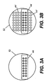
- the aspect ratio of a solid state light array 44 is shown in cross section, relative to an arbitrary aperture. As shown in Figure 3A , the aperture is underfilled, which may easily cause a poor etendue match at the spatial light modulator. In Figure 3B , the aspect ratio of the light source uses combined arrays 44 and 44' to achieve a better match to the circular aperture shown. Methods of combining multiple arrays 44 are described subsequently.
- One approach used to reduce thermal loading by embodiments of the present invention is to isolate the light sources from light modulation components using a waveguide structure.
- Light from multiple solid-state light source arrays is coupled into optical waveguides that deliver the light to the modulation device.
- the geometry of the light source-to-waveguide interface can be optimized so that the waveguide output is well-matched to the aspect ratio of the spatial light modulator.
- FIG. 4 shows a basic arrangement for projection apparatus 10 that is used in a number of embodiments of the present invention.
- Three light modulation assemblies 40r, 40g, and 40b are shown, each modulating one of the primary Red, Green, or Blue (RGB) colors from an illumination combiner 42.
- RGB Red, Green, or Blue
- an optional lens 50 directs light into a polarization maintaining light guide 52.
- a lens 54 directs light through an integrator 51, such as a fly's eye integrator or integrating bar, for example, to a spatial light modulator 60, which may be a DLP or other MEMS spatial light modulator component.
- this modulator must accept incident light of two orthogonal input polarization states and must preserve this polarization difference, providing as output light of two orthogonal polarization states that correspond to the respective input states.
- the output polarization states may, however, be rotated with respect to the input states.
- Projection optics 70 indicated generally in a dashed outline in Figure 4 due to many possible embodiments, then directs the modulated light to a display surface 80.
- Polarized glasses 58 worn by the viewer, have polarizers 76 and 78 that have orthogonal polarization axes that allow the left and right-eye images to be viewed independently.
- the overall arrangement shown in Figure 4 is a basic model used for subsequent embodiments of the present invention, with various arrangements used for illumination combiner 42.
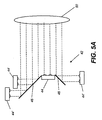
- Figure 5A shows one approach for combining multiple arrays 44 and 44' to form a larger array.
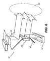
- Figure 6 shows the configuration of Figure 5A in perspective view.
- one or more interspersed mirrors 46 may be used to place the optical axis of additional arrays 44' in line with array 44 to provide the arrangement shown in cross-section in Figure 3B .
- a more direct example using combined arrays 44 is shown in Figure 5B .
- heat and spacing requirements may limit how many arrays 44 can be stacked in this manner.
- Figures 7A and 7B show an approach for combining multiple arrays 44a and 44b in order to form a larger array.
- Figure 7A shows solid-state light arrays 44a directing light to a polarization beam splitter (PBS) that reflects light of one polarization state toward lens 50.
- Figure 7B shows solid state light arrays 44b directing light through half wave plates 64, thereby changing the original polarization state of the emitted light. This light transmits through polarization beamsplitter 62.
- a logic controller 56 controls the timing of solid-state light arrays 44a and 44b.
- the timing diagram of Figure 8 shows, within any one of light modulation assemblies 40r, 40g, and 40b, how light that is directed to the same spatial light modulator 60 ( Figure 4 ) can be rapidly alternated between two orthogonal polarization states to provide left- and right-eye images accordingly.
- there are two banks of polarized lasers shown as solid state laser arrays 44a and 44b.
- Polarized lasers at arrays 44a and 44b provide light of orthogonal polarization states, such as using half wave plates 64 for one of these banks of arrays.
- arrays 44a are energized, as shown in Figure 7A . This light reflects from a polarization beamsplitter 62.
- arrays 44b are energized, as shown in Figure 7B .
- This light is transmitted through polarization beamsplitter 62.
- the light from both polarized lasers 44a and 44b may be used together to provide a brighter imager, or used at half power to balance the lifetime each laser source.
- Figures 9A and 9B show side and orthogonal views, respectively, of an embodiment of illumination combiner 42 that combines laser light from four solid-state light arrays 44, concentrated within a smaller area.
- a light-redirecting prism 30 has an incident face 32 that accepts light emitted from array 44 in an emission direction D1. Light is redirected to an output direction D2 that is substantially orthogonal to emission direction D1.
- Light redirecting prism 30 has a redirection surface 36 that has light-redirecting facets 38.
- Light-redirecting facets 38 are at an oblique angle relative to emission direction D1 and provide Total Internal Reflection (TIR) to light emitted from lasers 26.
- TIR Total Internal Reflection
- light arrays 44 have multiple lasers 26 that extend in a length direction L.
- Light-redirecting facets 38 and other facets on redirection surface 36 also extend in direction L.
- the cross-sectional side view of Figure 10 shows an alternate embodiment in which light-directing facets 38 of light redirecting prism 30 are scaled to redirect light from multiple rows of lasers 26 at a time.
- Incident face 32 may not be normal with respect to emission direction D1, allowing some offset to the arrangement of light arrays 44 and requiring that the index of refraction n of light redirecting prism 30 be taken into account.
- FIG. 11 shows how multiple light redirecting prisms 30 can be utilized to provide increased brightness in an embodiment that uses alternating polarization states.
- FIG. 12 shows another embodiment of light-redirecting prism 30 in illumination combiner 42 that provides an even more compact arrangement of illumination than the embodiment shown in Figures 9A-10 for using solid-state arrays.
- light redirecting prism has two redirection surfaces 36, accepting light from arrays 44 that are facing each other, with opposing emission directions D1 and D1'.
- Each redirection surface 36 has two types of facets: a light-redirecting facet 38 and an incidence facet 28 that is normal to the incident light from the corresponding array 44. This allows for easier alignment of the various laser modules to the light-redirecting prism 30 by retro-reflection of a small residual light from an antireflection coated face back into each of the lasers.
- This retro-reflection can be useful as a means of creating a subtle external cavity that may induce mode instability in laser. While such mode hopping may be considered noise under typical applications, this noise can add value in projection by further reducing the laser coherence (and inter-laser coherence) thereby reducing visual speckle at the image plane. Additionally, with this dual sided approach, laser modules are interleaved with light from differing modules neighboring each other, providing a source of further spatial mixing when the light is optically integrated further in the optical system. This again helps to reduce possible speckle and increase system uniformity.
- the schematic block diagram of Figure 14 shows an embodiment of projector apparatus 10 that uses light-redirecting prisms 30 in each color channel.
- Each light modulation assembly 40r, 40g, and 40b has a pair of light redirecting prisms 30 with a similar arrangement of polarization-directing components as that described for Figure 13 .
- polarized light from one or the other light redirecting prism 30 is directed through polarization maintaining light guide 52 to lens 50 and integrator 51 through polarization beamsplitter 62.
- Spatial light modulator 60 is a digital micromirror or other device that modulates light maintaining two orthogonal orientations of output light related to the orthogonal orientations of the input light.
- thin film coated surface 68 is treated to reflect or transmit incident light according to its incident angle, so that modulated light is directed to a dichroic combiner 82.
- Dichroic combiner 82 has an arrangement of dichroic surfaces 84 that selectively reflect or transmit light according to wavelength, combining the modulated light from each light modulation assembly 40r, 40g, and 40b onto a single optical path through projection optics 70.
- the schematic block diagram of Figure 15 shows an alternate embodiment of projector apparatus 10 in an embodiment similar to that of Figure 14 , but without light guides 52.
- This embodiment can be advantaged because light guides 52 can tend to degrade polarization of the transmitted light.
- lenslet arrays would offer advantages for uniformizing the illumination, since polarization states are maintained.
- this type of embodiment does not enjoy the advantages provided by light guide 52, such as improved heat dissipation.
- the laser light may be used in the near field condition or in the far field condition, where premixing of the light is provided to lower possible speckle and further improve the uniformity of the light going into the uniformizing optics of integrator 51.
- Polarized light is modulated by micromirrors or other micro-electromechanical devices.
- MEMS Micro-Electromechanical Structures
- DLP devices use a metallic reflector, typically formed from aluminum.
- Metal mirrors create very small phase shifts upon reflection when handling light from a skew angle.
- the preferred polarization orientation where the DLP device maintains the polarization state after reflection, has the polarization axis either in line with or orthogonal to the hinge pivot tilt of the micro-mirror, as shown in Figure 15 .
- Axis A indicates the hinge pivot line for a DLP micromirror.
- Polarization states oriented along other axes with regard to the plane of the micro-mirror can be used with minimal effect to the residual polarization, however.
- Light redirecting prism 30 can be made from many highly transmissive materials. For low power applications, plastics may be chosen, with molding processes being used that induce very little stress to the part. Similarly, it is desirable to have the materials chosen such that they induce minimal stress or thermally induced birefringence. Plastics such as acrylic or Zeonex from Zeon Chemicals would be examples of such materials. This is particularly important in the case where light redirecting prism 30 is used in a polarization based optical system.
- plastics may be impractical for use with light redirecting prism 30, since the heat buildup from even small level of optical absorption could ultimately damage the material and degrade transmission.
- glass would be preferred. Again stress birefringence could be a problem for polarization-based projectors. In this case, glass with low stress coefficient of birefringence, such as SF57, could be used.
- Another option would be to use a very low absorption optical glass, such as fused silica, to prevent heat up of the material and therefore keep the birefringence from occurring.
- a very low absorption optical glass such as fused silica
- fused silica may not be conducive to creating a molded glass component, thus requiring conventional polishing and or assembly of multiple pieces to make up the completed prism.
- a slow mold process would be preferred, and annealing is desirable to reduce any inherent stress.
- a clean up polarizer may be desired or necessary to remove any rotated polarization states that might develop from any residual birefringence. This is primarily a trade off of efficiency, component cost and required polarization purity.
- Embodiments of the present invention can be useful for shaping the aspect ratio of the light source so that it suits the aspect ratio of the spatial light modulator that is used.
- a modification to the current DLP package would be required regarding the cover plate hermetic package.
- the current package is designed to provide an environmental seal as well as a defect-free surface to prevent scattering from impacting image quality.
- the process of laser welding and thermally fusing windows into mechanical frames induces significant and inconsistent birefringence into each package. Variations in retardance of over 3nm have been observed across sample devices. This would negatively impact the maintenance of the polarization state out of the device. Therefore new window packaging would be necessary in order to properly utilize DLP devices with polarized light.
- Packages can be improved by utilizing a glass that has a low coefficient stress or thermally induced birefringence, such as SF57.
- An alternate approach would be to provide stress free mounting of a window to the window frame, for example using RTV to bond the window in place. Further isolation, such that the mechanics of the window frame are rigid with respect to the window, but flexible with respect to the bonding surfaces to the chip frame, would also be advantageous . Likewise, this approach could be reversed. Further, it would benefit the procedure for bonding the window to the frame and the frame to the chip mounting if performed at the carefully controlled chip operational temperatures, so as to avoid stresses from an operational and packaging temperature difference.
- Embodiments of the present invention can be used with light guides 52 of different dimensions, allowing the light guide to be not only flexible, but also shaped with substantially the same aspect ratio to that of the modulator. For digital cinema this ratio would be approximately 1.9:1.
- An alternate embodiment could use a square core fiber.
- a round core optical waveguide, such as common multimode optical fiber can be utilized.
- MEMS Micro-Electromechanical Structures
- DLP devices use a metallic reflector, typically formed from aluminum.
- Metal mirrors create very small phase shifts upon reflection when handling light from a skew angle, where the plane polarized light vibrates off from either in the plane of incidence or perpendicular to it.
- the preferred polarization orientation where the DLP device maintains the polarization state after reflection, has the polarization axis either in line with or orthogonal to the hinge pivot tilt of the micro-mirror 74 (where the plane of polarization, either s or p, is at a normal incidence to the mirror), as shown in Figure 16 .
- Axis A indicates the hinge pivot line for a DLP micromirror.
- Polarization states oriented along other axes with regard to the plane of the micro-mirror can be used with minimal effect to the residual polarization, however. This residual ellipticity results in crosstalk between the two polarization states.
Landscapes
- Physics & Mathematics (AREA)
- General Physics & Mathematics (AREA)
- Engineering & Computer Science (AREA)
- Multimedia (AREA)
- Signal Processing (AREA)
- Optics & Photonics (AREA)
- Microscoopes, Condenser (AREA)
- Stereoscopic And Panoramic Photography (AREA)
- Transforming Electric Information Into Light Information (AREA)
- Testing, Inspecting, Measuring Of Stereoscopic Televisions And Televisions (AREA)
- Optical Elements Other Than Lenses (AREA)
Claims (4)
- Système permettant de visualiser des images stéréoscopiques, comprenant :des verres polarisés (58) portés par un spectateur pour visualiser des images stéréoscopiques formées sur une surface d'affichage (80), dans lequel un filtre polarisé (76) pour un premier oeil transmet une lumière polarisée qui est orthogonale à la lumière polarisée transmise par un filtre polarisé (78) pour le deuxième oeil ; etun projecteur numérique d'image stéréoscopique (10) comprenant :un système d'éclairement comprenant :une première et une deuxième sources de lumière polarisée (44a, 44b), dans lesquelles la première et la deuxième sources de lumière polarisée ont des axes de polarisation disposés de façon orthogonale ; etun séparateur de faisceau à polarisation (62) disposé de manière à diriger la lumière ayant les première et deuxième polarisations le long d'un axe d'éclairement commun ;un système contrôleur (56) qui alimente alternativement les première et deuxième sources de lumière polarisée (44a, 44b) pour produire un éclairement ayant une seule polarisation à la fois;un seul modulateur spatial de lumière MEMS (60) permettant de moduler alternativement les faisceaux lumineux ayant les première et deuxième polarisations sur l'axe d'éclairement commun ; etune optique de projection (70) dans le trajet de la lumière modulée émise par le modulateur spatial de lumière MEMS (60) et redirigeant la lumière sur la surface d'affichage (80).
- Projecteur numérique d'image stéréoscopique selon la revendication 1, dans lequel le système d'éclairement est un premier système d'éclairement, dans lequel le séparateur de faisceau à polarisation (62) est un premier séparateur de faisceau à polarisation, dans lequel l'axe d'éclairement commun est un premier axe d'éclairement commun, dans lequel le modulateur spatial de lumière MEMS (60) est un premier modulateur spatial de lumière MEMS et dans lequel le projecteur numérique d'image stéréoscopique comprend aussi :au moins un deuxième système d'éclairement comprenant :une troisième et une quatrième sources de lumière polarisée (44a, 44b), dans lesquelles les troisième et quatrième sources de lumière polarisée (44a, 44b) ont des axes de polarisation disposés de façon orthogonale et produisent une lumière dans une bande de longueurs d'onde différente de celle des première et deuxième sources de lumière polarisée ; etun deuxième séparateur de faisceau à polarisation (62) disposé de manière à diriger la lumière ayant les troisième et quatrième polarisations le long d'un deuxième axe d'éclairement commun ; etun deuxième modulateur spatial de lumière MEMS (60) permettant de moduler alternativement les faisceaux lumineux ayant les troisième et quatrième polarisations sur le deuxième axe d'éclairement commun ;dans lequel l'optique de projection (70) dirige la lumière émise par les premier et deuxième systèmes d'éclairement sur la surface d'affichage (80) pour produire une image en couleurs ayant au moins deux bandes spectrales.
- Appareil de projection selon la revendication 1, dans lequel le modulateur spatial de lumière MEMS (60) comprend une structure métallique réfléchissante (74), et dans lequel le plan de polarisation de la lumière polarisée linéairement incidente sur la structure métallique (74) est soit sensiblement perpendiculaire au plan de la structure métallique réfléchissante (74) soit sensiblement dans le plan de la structure métallique réfléchissante (74).
- Appareil de projection couleur comprenant :a) au moins deux ensembles de modulation de la lumière pour un projecteur numérique d'image, chaque ensemble de modulation de la lumière ayant une bande de longueurs d'onde prédéterminée et comprenant :i) une première source de lumière polarisée comprenant :au moins deux réseaux laser à solide (44a) disposés de manière à produire une lumière ayant une première polarisation dans une première direction d'émission, dans lesquels chaque réseau laser (44a) comprend une pluralité de lasers étendus dans une première direction longitudinale ; etun premier prisme de redirection de la lumière (30) comprenant :une première surface incidente (32) disposée de manière à recevoir la lumière incidente dans ladite première direction d'émission ;une première surface de redirection (36) ayant une pluralité de facettes de redirection de la lumière (38), chaque facette de redirection de la lumière (38) étant étendue dans la direction longitudinale et orientée à un angle oblique par rapport à la première direction d'émission, dans lequel l'orientation angulaire oblique fournit une surface de réflexion à la lumière incidente ; etune première surface de sortie (34) permettant de fournir une lumière redirigée ayant la première polarisation émise par les facettes de redirection de la lumière (38) ;ii) une deuxième source de lumière polarisée comprenant :au moins deux réseaux laser à solide (44b) disposés de manière à produire une lumière ayant la première polarisation dans une deuxième direction d'émission, dans lesquels chaque réseau laser comprend une pluralité de lasers étendus dans une deuxième direction longitudinale ;une lame demi-onde (64) permettant de conditionner la lumière émise par la deuxième source de lumière polarisée pour produire une lumière ayant une deuxième polarisation qui est orthogonale à la première polarisation ; etun deuxième prisme de redirection de la lumière (30) comprenant :une deuxième surface incidente (32) disposée de manière à recevoir la lumière incidente dans ladite deuxième direction d'émission ;une deuxième surface de redirection (36) ayant une pluralité de facettes de redirection de la lumière (38), chaque facette de redirection de la lumière (38) étant étendue dans la deuxième direction longitudinale et orientée à un angle oblique par rapport à la deuxième direction d'émission, dans lequel l'orientation angulaire oblique fournit une surface de réflexion à la lumière incidente ; etune deuxième surface de sortie (34) permettant de fournir une lumière redirigée ayant la deuxième polarisation émise par les facettes de redirection de la lumière (38) ;iii) un séparateur de faisceau à polarisation (62) disposé de manière à diriger la lumière ayant la première ou la deuxième polarisation en tant qu'éclairement le long d'un axe d'éclairement commun ;iv) un système contrôleur (56) qui alimente alternativement les première et deuxième sources de lumière polarisée (44a, 44b) pour produire un éclairement ayant une seule polarisation à la fois;v) un seul modulateur spatial de lumière (60) permettant de moduler alternativement les faisceaux lumineux ayant les première et deuxième polarisations, disposé de manière à recevoir l'éclairement sur l'axe d'éclairement commun et à produire une lumière de sortie modulée ;b) un combinateur de couleurs (82) disposé de manière à recevoir la lumière de sortie modulée par chacun des au moins deux ensembles de modulation de la lumière et à diriger la lumière modulée sur un axe de sortie ; etc) un objectif de projection (70) disposé de manière à diriger la lumière modulée vers une surface d'affichage (80).
Applications Claiming Priority (2)
| Application Number | Priority Date | Filing Date | Title |
|---|---|---|---|
| US11/948,048 US7871165B2 (en) | 2007-11-30 | 2007-11-30 | Stereo projection apparatus using polarized solid state light sources |
| PCT/US2008/012994 WO2009073089A1 (fr) | 2007-11-30 | 2008-11-21 | Appareil de projection stéréo |
Publications (2)
| Publication Number | Publication Date |
|---|---|
| EP2215848A1 EP2215848A1 (fr) | 2010-08-11 |
| EP2215848B1 true EP2215848B1 (fr) | 2013-07-31 |
Family
ID=40377472
Family Applications (1)
| Application Number | Title | Priority Date | Filing Date |
|---|---|---|---|
| EP08857153.4A Not-in-force EP2215848B1 (fr) | 2007-11-30 | 2008-11-21 | Appareil de projection stéréo |
Country Status (7)
| Country | Link |
|---|---|
| US (1) | US7871165B2 (fr) |
| EP (1) | EP2215848B1 (fr) |
| JP (1) | JP2011505593A (fr) |
| CN (1) | CN101878655B (fr) |
| CA (1) | CA2704029A1 (fr) |
| TW (1) | TWI450017B (fr) |
| WO (1) | WO2009073089A1 (fr) |
Families Citing this family (91)
| Publication number | Priority date | Publication date | Assignee | Title |
|---|---|---|---|---|
| US8139130B2 (en) | 2005-07-28 | 2012-03-20 | Omnivision Technologies, Inc. | Image sensor with improved light sensitivity |
| US8274715B2 (en) | 2005-07-28 | 2012-09-25 | Omnivision Technologies, Inc. | Processing color and panchromatic pixels |
| US7916362B2 (en) | 2006-05-22 | 2011-03-29 | Eastman Kodak Company | Image sensor with improved light sensitivity |
| US8031258B2 (en) | 2006-10-04 | 2011-10-04 | Omnivision Technologies, Inc. | Providing multiple video signals from single sensor |
| CN101377572A (zh) * | 2007-08-28 | 2009-03-04 | 鸿富锦精密工业(深圳)有限公司 | 立体投影光学系统 |
| US7959297B2 (en) | 2008-05-15 | 2011-06-14 | Eastman Kodak Company | Uniform speckle reduced laser projection using spatial and temporal mixing |
| US7915067B2 (en) * | 2008-07-09 | 2011-03-29 | Eastman Kodak Company | Backside illuminated image sensor with reduced dark current |
| US7859033B2 (en) | 2008-07-09 | 2010-12-28 | Eastman Kodak Company | Wafer level processing for backside illuminated sensors |
| US7926951B2 (en) * | 2008-07-11 | 2011-04-19 | Eastman Kodak Company | Laser illuminated micro-mirror projector |
| DE102008051252B4 (de) * | 2008-10-10 | 2016-09-08 | Sypro Optics Gmbh | Projektionsobjektiv und Projektor |
| US8016422B2 (en) * | 2008-10-28 | 2011-09-13 | Eastman Kodak Company | Etendue maintaining polarization switching system and related methods |
| US20130223846A1 (en) | 2009-02-17 | 2013-08-29 | Trilumina Corporation | High speed free-space optical communications |
| US8995493B2 (en) | 2009-02-17 | 2015-03-31 | Trilumina Corp. | Microlenses for multibeam arrays of optoelectronic devices for high frequency operation |
| US8995485B2 (en) | 2009-02-17 | 2015-03-31 | Trilumina Corp. | High brightness pulsed VCSEL sources |
| US10244181B2 (en) | 2009-02-17 | 2019-03-26 | Trilumina Corp. | Compact multi-zone infrared laser illuminator |
| US10038304B2 (en) | 2009-02-17 | 2018-07-31 | Trilumina Corp. | Laser arrays for variable optical properties |
| US8224082B2 (en) * | 2009-03-10 | 2012-07-17 | Omnivision Technologies, Inc. | CFA image with synthetic panchromatic image |
| US8068153B2 (en) * | 2009-03-27 | 2011-11-29 | Omnivision Technologies, Inc. | Producing full-color image using CFA image |
| US8045024B2 (en) * | 2009-04-15 | 2011-10-25 | Omnivision Technologies, Inc. | Producing full-color image with reduced motion blur |
| US8203633B2 (en) * | 2009-05-27 | 2012-06-19 | Omnivision Technologies, Inc. | Four-channel color filter array pattern |
| US8237831B2 (en) * | 2009-05-28 | 2012-08-07 | Omnivision Technologies, Inc. | Four-channel color filter array interpolation |
| DE112010002177B4 (de) | 2009-05-29 | 2023-12-28 | Kyocera Sld Laser, Inc. | Projektionssystem |
| US10108079B2 (en) | 2009-05-29 | 2018-10-23 | Soraa Laser Diode, Inc. | Laser light source for a vehicle |
| US8125546B2 (en) * | 2009-06-05 | 2012-02-28 | Omnivision Technologies, Inc. | Color filter array pattern having four-channels |
| US8253832B2 (en) * | 2009-06-09 | 2012-08-28 | Omnivision Technologies, Inc. | Interpolation for four-channel color filter array |
| US8864313B2 (en) * | 2009-06-15 | 2014-10-21 | Eastman Kodak Company | Dynamic illumination control for laser projection display |
| US8142021B2 (en) * | 2009-06-25 | 2012-03-27 | Eastman Kodak Company | Dump path light intensity sensing in light projector |
| US8220938B2 (en) * | 2009-06-25 | 2012-07-17 | Eastman Kodak Company | Image path light intensity sensing during a blanking period between a left-eye light beam and a right-eye light beam in a stereoscopic light projector |
| US8237777B2 (en) * | 2009-06-25 | 2012-08-07 | Eastman Kodak Company | Stereoscopic image intensity balancing in light projector |
| US20100328611A1 (en) * | 2009-06-25 | 2010-12-30 | Silverstein Barry D | Leakage light intensity sensing in light projector |
| US8162483B2 (en) * | 2009-06-25 | 2012-04-24 | Eastman Kodak Company | Hierarchical light intensity control in light projector |
| US8220931B2 (en) * | 2009-07-07 | 2012-07-17 | Eastman Kodak Company | Etendue reduced stereo projection using segmented disk |
| US8066382B2 (en) * | 2009-07-14 | 2011-11-29 | Eastman Kodak Company | Stereoscopic projector with rotating segmented disk |
| US8979338B2 (en) | 2009-12-19 | 2015-03-17 | Trilumina Corp. | System for combining laser array outputs into a single beam carrying digital data |
| WO2011075609A1 (fr) * | 2009-12-19 | 2011-06-23 | Trilumina Corporation | Système et procédé de combinaison de réseaux de lasers pour sorties numériques |
| JP2011133782A (ja) * | 2009-12-25 | 2011-07-07 | Casio Computer Co Ltd | 光源ユニット及びプロジェクタ |
| US20110261174A1 (en) * | 2010-04-27 | 2011-10-27 | Silverstein Barry D | Stereoscopic digital projection apparatus using polarized light |
| DE102010030138A1 (de) | 2010-06-15 | 2011-12-15 | Fraunhofer-Gesellschaft zur Förderung der angewandten Forschung e.V. | Projektionsdisplay und Verfahren zum Anzeigen eines Gesamtbilds |
| US20120021150A1 (en) * | 2010-07-21 | 2012-01-26 | Ulrich Wilhelm Heinz Neukirch | Optical window assembly having low birefringence |
| WO2012017263A1 (fr) * | 2010-08-06 | 2012-02-09 | Fci | Système de couplage optique |
| JP5333472B2 (ja) * | 2011-02-04 | 2013-11-06 | カシオ計算機株式会社 | 光源ユニット、光源装置及びプロジェクタ |
| JP5842167B2 (ja) * | 2011-02-28 | 2016-01-13 | パナソニックIpマネジメント株式会社 | 光源装置及び投写型映像表示装置 |
| CN102759846B (zh) * | 2011-04-29 | 2015-02-04 | 台达电子工业股份有限公司 | 光源系统 |
| TWI447435B (zh) * | 2011-04-29 | 2014-08-01 | Delta Electronics Inc | 光源系統 |
| GB201108000D0 (en) * | 2011-05-13 | 2011-06-29 | Barco Nv | Polarization preserving dlp optical architecture |
| GB201109208D0 (en) | 2011-06-01 | 2011-07-13 | Barco Nv | Apparatus and method for combining laser beams of different polarization |
| DE102011052802B4 (de) * | 2011-08-18 | 2014-03-13 | Sick Ag | 3D-Kamera und Verfahren zur Überwachung eines Raumbereichs |
| US11095365B2 (en) | 2011-08-26 | 2021-08-17 | Lumentum Operations Llc | Wide-angle illuminator module |
| CN103048792B (zh) | 2011-10-11 | 2015-10-07 | 深圳市光峰光电技术有限公司 | 光源系统与激光光源 |
| WO2013098941A1 (fr) * | 2011-12-27 | 2013-07-04 | Necディスプレイソリューションズ株式会社 | Unite de synthese par lumiere d'excitation, unite d'eclairage et dispositif d'affichage par projection |
| US8864314B2 (en) * | 2012-01-17 | 2014-10-21 | Eastman Kodak Company | Stereoscopic projection system using tunable light emitters |
| US8992024B2 (en) | 2012-01-25 | 2015-03-31 | International Business Machines Corporation | Three dimensional image projector with circular light polarization |
| US8960913B2 (en) | 2012-01-25 | 2015-02-24 | International Busniess Machines Corporation | Three dimensional image projector with two color imaging |
| US9104048B2 (en) | 2012-01-25 | 2015-08-11 | International Business Machines Corporation | Three dimensional image projector with single modulator |
| US20130188149A1 (en) | 2012-01-25 | 2013-07-25 | International Business Machines Corporation | Three dimensional image projector |
| US9004700B2 (en) | 2012-01-25 | 2015-04-14 | International Business Machines Corporation | Three dimensional image projector stabilization circuit |
| US8985785B2 (en) | 2012-01-25 | 2015-03-24 | International Business Machines Corporation | Three dimensional laser image projector |
| US9325977B2 (en) | 2012-01-25 | 2016-04-26 | International Business Machines Corporation | Three dimensional LCD monitor display |
| WO2013123592A1 (fr) | 2012-02-23 | 2013-08-29 | Switch Materials Inc. | Filtre optique à source de lumière |
| CN102591123B (zh) * | 2012-03-13 | 2014-12-10 | 苏州大学 | 一种实时三维显示装置及显示方法 |
| US8872985B2 (en) | 2012-04-13 | 2014-10-28 | Red.Com, Inc. | Video projector system |
| US9025086B2 (en) | 2012-04-13 | 2015-05-05 | Red.Com, Inc. | Video projector system |
| TWI467242B (zh) * | 2012-05-29 | 2015-01-01 | Delta Electronics Inc | 提供複數視角影像之投影裝置 |
| JP2012230403A (ja) * | 2012-06-29 | 2012-11-22 | Casio Comput Co Ltd | 光源装置及びプロジェクタ |
| TWI461740B (zh) | 2012-10-31 | 2014-11-21 | Delta Electronics Inc | 立體顯示固態光源模組 |
| KR102135345B1 (ko) * | 2013-01-22 | 2020-07-17 | 엘지전자 주식회사 | 영상투사장치 |
| CN103809356B (zh) * | 2013-08-02 | 2019-12-10 | 杨毅 | 屏幕 |
| CN103809359B (zh) * | 2013-08-02 | 2017-11-14 | 杨毅 | 屏幕 |
| CN103809361B (zh) * | 2013-08-02 | 2017-11-14 | 杨毅 | 投影显示系统 |
| CN103809360A (zh) * | 2013-08-02 | 2014-05-21 | 吴震 | 投影显示系统 |
| TWI498598B (zh) | 2013-11-12 | 2015-09-01 | Delta Electronics Inc | 立體裸視投影裝置及顯示裝置 |
| TWI512334B (zh) * | 2013-11-28 | 2015-12-11 | Delta Electronics Inc | 光源系統及顯示裝置 |
| CN104678691A (zh) * | 2013-11-28 | 2015-06-03 | 台达电子工业股份有限公司 | 光源系统及显示装置 |
| CN103676186A (zh) * | 2013-12-25 | 2014-03-26 | 中国华录集团有限公司 | 激光二极管布局系统和方法 |
| EP3143763B8 (fr) | 2014-05-15 | 2023-12-27 | MTT Innovation Incorporated | Projecteur de lumière et méthode d'affichage d'une image |
| TWI598633B (zh) * | 2014-08-05 | 2017-09-11 | 佳能股份有限公司 | 光源設備,照明裝置,曝光設備,及裝置製造方法 |
| CN112576950A (zh) * | 2014-08-14 | 2021-03-30 | Mtt创新公司 | 多激光器光源 |
| EP3241072B1 (fr) | 2014-12-31 | 2020-09-16 | Dolby Laboratories Licensing Corporation | Prisme d'entrée discret à contraste élevé pour des projecteurs d'image |
| TWI553392B (zh) * | 2015-01-06 | 2016-10-11 | 台達電子工業股份有限公司 | 偏振投影裝置與應用其之偏振投影系統 |
| JP6244558B2 (ja) * | 2015-01-30 | 2017-12-13 | パナソニックIpマネジメント株式会社 | 光源装置及び投写型映像表示装置 |
| US9874805B2 (en) | 2015-01-30 | 2018-01-23 | Panasonic Intellectual Property Management Co., Ltd. | Light source apparatus and projection display apparatus |
| CN105573023B (zh) * | 2015-11-25 | 2017-11-10 | 全普光电科技(上海)有限公司 | 多mems激光投影装置及其方法 |
| KR102589283B1 (ko) * | 2015-12-08 | 2023-10-16 | 한국전기연구원 | 거울을 이용한 다중 광원 기판 |
| CN107463057A (zh) * | 2016-06-02 | 2017-12-12 | 中强光电股份有限公司 | 投影系统与照明系统 |
| EP3840370B1 (fr) * | 2016-09-30 | 2022-08-10 | Dolby Laboratories Licensing Corporation | Combinaison de faisceaux pour la projection en surbrillance |
| WO2019097431A1 (fr) * | 2017-11-14 | 2019-05-23 | Imax Theatres International Limited | Conditionnement de lumière d'affichage à vision directe pour cinéma |
| CN110082998A (zh) * | 2018-01-25 | 2019-08-02 | 深圳光峰科技股份有限公司 | 激光合光装置及显示设备 |
| CN111258159B (zh) * | 2018-11-30 | 2022-07-12 | 中强光电股份有限公司 | 照明系统及投影装置 |
| US11239637B2 (en) | 2018-12-21 | 2022-02-01 | Kyocera Sld Laser, Inc. | Fiber delivered laser induced white light system |
| US11421843B2 (en) | 2018-12-21 | 2022-08-23 | Kyocera Sld Laser, Inc. | Fiber-delivered laser-induced dynamic light system |
| JP7361274B2 (ja) | 2019-12-18 | 2023-10-16 | パナソニックIpマネジメント株式会社 | 光源装置および投写型画像表示装置 |
Citations (1)
| Publication number | Priority date | Publication date | Assignee | Title |
|---|---|---|---|---|
| DE19626097C1 (de) * | 1996-06-28 | 1997-10-30 | Siemens Nixdorf Inf Syst | Verfahren und Anordnung zur Bilddarstellung auf einer Großbildprojektionsfläche mittels eines einen DMD-Chip aufweisenden DMD-Projektors |
Family Cites Families (36)
| Publication number | Priority date | Publication date | Assignee | Title |
|---|---|---|---|---|
| GB2317524A (en) * | 1996-09-19 | 1998-03-25 | Sharp Kk | Three dimensional stereoscopic projection display |
| US6240116B1 (en) * | 1997-08-14 | 2001-05-29 | Sdl, Inc. | Laser diode array assemblies with optimized brightness conservation |
| US5987043A (en) * | 1997-11-12 | 1999-11-16 | Opto Power Corp. | Laser diode arrays with offset components |
| US6583921B2 (en) * | 1999-12-28 | 2003-06-24 | Texas Instruments Incorporated | Micromechanical device and method for non-contacting edge-coupled operation |
| JP2003031872A (ja) * | 2001-07-19 | 2003-01-31 | Ricoh Co Ltd | レーザ照明装置およびこれを用いた画像表示装置 |
| US6594090B2 (en) * | 2001-08-27 | 2003-07-15 | Eastman Kodak Company | Laser projection display system |
| US6547396B1 (en) * | 2001-12-27 | 2003-04-15 | Infocus Corporation | Stereographic projection system |
| JP4387688B2 (ja) * | 2002-11-07 | 2009-12-16 | Necディスプレイソリューションズ株式会社 | 液晶プロジェクタ |
| JP2004205919A (ja) * | 2002-12-26 | 2004-07-22 | Victor Co Of Japan Ltd | 投射型立体表示装置 |
| US7832869B2 (en) * | 2003-10-21 | 2010-11-16 | Barco N.V. | Method and device for performing stereoscopic image display based on color selective filters |
| JP4063213B2 (ja) * | 2003-12-09 | 2008-03-19 | カシオ計算機株式会社 | 光源装置及びそれを備えたプロジェクタ |
| DE10361915B4 (de) * | 2003-12-29 | 2009-03-05 | Bausenwein, Bernhard, Dr. | 2-Kanal-Stereo-Bildanzeigevorrichtung mit mikroelektromechanischen Systemen |
| US7360900B2 (en) * | 2004-03-10 | 2008-04-22 | Seiko Epson Corporation | Illuminating apparatus, image display apparatus, and projector |
| GB0405747D0 (en) * | 2004-03-15 | 2004-04-21 | Imec Inter Uni Micro Electr | Projector system comprising pulsed light sources |
| JP2007003847A (ja) * | 2005-06-24 | 2007-01-11 | Sanyo Electric Co Ltd | 照明装置及び投写型映像表示装置 |
| JP2006065054A (ja) * | 2004-08-27 | 2006-03-09 | Nitto Kogaku Kk | プロジェクター用光学エンジン |
| JP4289288B2 (ja) * | 2004-12-03 | 2009-07-01 | セイコーエプソン株式会社 | 光源装置及び画像表示装置 |
| JP2006220911A (ja) * | 2005-02-10 | 2006-08-24 | Seiko Epson Corp | 照明装置及び画像表示装置 |
| JP4244957B2 (ja) * | 2005-05-19 | 2009-03-25 | カシオ計算機株式会社 | 光源装置及び投影装置 |
| JP4254747B2 (ja) * | 2005-05-31 | 2009-04-15 | カシオ計算機株式会社 | 光源装置及び投影装置 |
| JP4085395B2 (ja) * | 2005-06-10 | 2008-05-14 | ミネベア株式会社 | 光源装置およびそれを用いた画像表示装置 |
| JP2007017536A (ja) * | 2005-07-05 | 2007-01-25 | Ricoh Co Ltd | プロジェクタ装置 |
| US20070024959A1 (en) * | 2005-07-26 | 2007-02-01 | Infocus Corporation | Laser combiner |
| US7559653B2 (en) * | 2005-12-14 | 2009-07-14 | Eastman Kodak Company | Stereoscopic display apparatus using LCD panel |
| US7528906B2 (en) * | 2006-01-23 | 2009-05-05 | Real D | Achromatic polarization switches |
| KR101206031B1 (ko) * | 2006-01-25 | 2012-11-28 | 삼성전자주식회사 | 변조 가능한 외부 공진기형 면발광 레이저 및 이를 채용한디스플레이 장치 |
| KR100796766B1 (ko) | 2006-05-29 | 2008-01-22 | (주)레드로버 | 프로젝션용 스테레오 광학엔진 구조 |
| WO2007149189A2 (fr) * | 2006-05-31 | 2007-12-27 | University Of New Hampshire | Système de réseau de diodes laser à rétrécissement spectral |
| WO2008076104A1 (fr) | 2006-12-18 | 2008-06-26 | Thomson Licensing | Projecteur à large gamme de couleurs |
| US20080276379A1 (en) | 2007-05-10 | 2008-11-13 | Macdonald John Gavin | Methods for discharging colorants |
| US20090122272A1 (en) * | 2007-11-09 | 2009-05-14 | Silverstein Barry D | Projection apparatus using solid-state light source array |
| US20090153752A1 (en) * | 2007-12-14 | 2009-06-18 | Silverstein Barry D | Projector using independent multiple wavelength light sources |
| US7891816B2 (en) * | 2008-02-25 | 2011-02-22 | Eastman Kodak Company | Stereo projection using polarized solid state light sources |
| US7959297B2 (en) * | 2008-05-15 | 2011-06-14 | Eastman Kodak Company | Uniform speckle reduced laser projection using spatial and temporal mixing |
| US7926951B2 (en) * | 2008-07-11 | 2011-04-19 | Eastman Kodak Company | Laser illuminated micro-mirror projector |
| US8016422B2 (en) * | 2008-10-28 | 2011-09-13 | Eastman Kodak Company | Etendue maintaining polarization switching system and related methods |
-
2007
- 2007-11-30 US US11/948,048 patent/US7871165B2/en not_active Expired - Fee Related
-
2008
- 2008-11-21 CN CN2008801183981A patent/CN101878655B/zh not_active Expired - Fee Related
- 2008-11-21 CA CA2704029A patent/CA2704029A1/fr not_active Abandoned
- 2008-11-21 EP EP08857153.4A patent/EP2215848B1/fr not_active Not-in-force
- 2008-11-21 WO PCT/US2008/012994 patent/WO2009073089A1/fr active Application Filing
- 2008-11-21 JP JP2010535969A patent/JP2011505593A/ja active Pending
- 2008-11-28 TW TW097146481A patent/TWI450017B/zh not_active IP Right Cessation
Patent Citations (1)
| Publication number | Priority date | Publication date | Assignee | Title |
|---|---|---|---|---|
| DE19626097C1 (de) * | 1996-06-28 | 1997-10-30 | Siemens Nixdorf Inf Syst | Verfahren und Anordnung zur Bilddarstellung auf einer Großbildprojektionsfläche mittels eines einen DMD-Chip aufweisenden DMD-Projektors |
Also Published As
| Publication number | Publication date |
|---|---|
| TW200931159A (en) | 2009-07-16 |
| CA2704029A1 (fr) | 2009-06-11 |
| US7871165B2 (en) | 2011-01-18 |
| CN101878655B (zh) | 2013-02-06 |
| JP2011505593A (ja) | 2011-02-24 |
| CN101878655A (zh) | 2010-11-03 |
| WO2009073089A1 (fr) | 2009-06-11 |
| EP2215848A1 (fr) | 2010-08-11 |
| US20090141242A1 (en) | 2009-06-04 |
| TWI450017B (zh) | 2014-08-21 |
Similar Documents
| Publication | Publication Date | Title |
|---|---|---|
| EP2215848B1 (fr) | Appareil de projection stéréo | |
| EP2220533B1 (fr) | Projecteur utilisant des sources de lumière indépendantes à longueurs d'onde multiples | |
| EP2248346B1 (fr) | Projection stéréo utilisant des sources lumineuses polarisées à semi-conducteurs | |
| EP2423744B1 (fr) | Projecteur à micromiroirs éclairé au laser | |
| EP2454633B1 (fr) | Projecteur stéréoscopique avec disque segmenté rotatif | |
| US8220931B2 (en) | Etendue reduced stereo projection using segmented disk | |
| EP2274918B1 (fr) | Projection laser utilisant un mélange spatial et temporel | |
| US20110261174A1 (en) | Stereoscopic digital projection apparatus using polarized light |
Legal Events
| Date | Code | Title | Description |
|---|---|---|---|
| PUAI | Public reference made under article 153(3) epc to a published international application that has entered the european phase |
Free format text: ORIGINAL CODE: 0009012 |
|
| 17P | Request for examination filed |
Effective date: 20100510 |
|
| AK | Designated contracting states |
Kind code of ref document: A1 Designated state(s): AT BE BG CH CY CZ DE DK EE ES FI FR GB GR HR HU IE IS IT LI LT LU LV MC MT NL NO PL PT RO SE SI SK TR |
|
| AX | Request for extension of the european patent |
Extension state: AL BA MK RS |
|
| DAX | Request for extension of the european patent (deleted) | ||
| REG | Reference to a national code |
Ref country code: DE Ref legal event code: R079 Ref document number: 602008026507 Country of ref document: DE Free format text: PREVIOUS MAIN CLASS: H04N0013000000 Ipc: H04N0013040000 |
|
| GRAP | Despatch of communication of intention to grant a patent |
Free format text: ORIGINAL CODE: EPIDOSNIGR1 |
|
| RIC1 | Information provided on ipc code assigned before grant |
Ipc: H04N 13/04 20060101AFI20130214BHEP |
|
| GRAS | Grant fee paid |
Free format text: ORIGINAL CODE: EPIDOSNIGR3 |
|
| GRAA | (expected) grant |
Free format text: ORIGINAL CODE: 0009210 |
|
| AK | Designated contracting states |
Kind code of ref document: B1 Designated state(s): AT BE BG CH CY CZ DE DK EE ES FI FR GB GR HR HU IE IS IT LI LT LU LV MC MT NL NO PL PT RO SE SI SK TR |
|
| REG | Reference to a national code |
Ref country code: GB Ref legal event code: FG4D Ref country code: CH Ref legal event code: EP |
|
| REG | Reference to a national code |
Ref country code: AT Ref legal event code: REF Ref document number: 625233 Country of ref document: AT Kind code of ref document: T Effective date: 20130815 |
|
| REG | Reference to a national code |
Ref country code: IE Ref legal event code: FG4D |
|
| REG | Reference to a national code |
Ref country code: DE Ref legal event code: R096 Ref document number: 602008026507 Country of ref document: DE Effective date: 20130926 |
|
| REG | Reference to a national code |
Ref country code: NL Ref legal event code: T3 |
|
| REG | Reference to a national code |
Ref country code: AT Ref legal event code: MK05 Ref document number: 625233 Country of ref document: AT Kind code of ref document: T Effective date: 20130731 |
|
| REG | Reference to a national code |
Ref country code: LT Ref legal event code: MG4D |
|
| PG25 | Lapsed in a contracting state [announced via postgrant information from national office to epo] |
Ref country code: HR Free format text: LAPSE BECAUSE OF FAILURE TO SUBMIT A TRANSLATION OF THE DESCRIPTION OR TO PAY THE FEE WITHIN THE PRESCRIBED TIME-LIMIT Effective date: 20130731 Ref country code: AT Free format text: LAPSE BECAUSE OF FAILURE TO SUBMIT A TRANSLATION OF THE DESCRIPTION OR TO PAY THE FEE WITHIN THE PRESCRIBED TIME-LIMIT Effective date: 20130731 Ref country code: NO Free format text: LAPSE BECAUSE OF FAILURE TO SUBMIT A TRANSLATION OF THE DESCRIPTION OR TO PAY THE FEE WITHIN THE PRESCRIBED TIME-LIMIT Effective date: 20131031 Ref country code: CY Free format text: LAPSE BECAUSE OF FAILURE TO SUBMIT A TRANSLATION OF THE DESCRIPTION OR TO PAY THE FEE WITHIN THE PRESCRIBED TIME-LIMIT Effective date: 20130904 Ref country code: SE Free format text: LAPSE BECAUSE OF FAILURE TO SUBMIT A TRANSLATION OF THE DESCRIPTION OR TO PAY THE FEE WITHIN THE PRESCRIBED TIME-LIMIT Effective date: 20130731 Ref country code: PT Free format text: LAPSE BECAUSE OF FAILURE TO SUBMIT A TRANSLATION OF THE DESCRIPTION OR TO PAY THE FEE WITHIN THE PRESCRIBED TIME-LIMIT Effective date: 20131202 Ref country code: IS Free format text: LAPSE BECAUSE OF FAILURE TO SUBMIT A TRANSLATION OF THE DESCRIPTION OR TO PAY THE FEE WITHIN THE PRESCRIBED TIME-LIMIT Effective date: 20131130 Ref country code: LT Free format text: LAPSE BECAUSE OF FAILURE TO SUBMIT A TRANSLATION OF THE DESCRIPTION OR TO PAY THE FEE WITHIN THE PRESCRIBED TIME-LIMIT Effective date: 20130731 |
|
| PG25 | Lapsed in a contracting state [announced via postgrant information from national office to epo] |
Ref country code: LV Free format text: LAPSE BECAUSE OF FAILURE TO SUBMIT A TRANSLATION OF THE DESCRIPTION OR TO PAY THE FEE WITHIN THE PRESCRIBED TIME-LIMIT Effective date: 20130731 Ref country code: SI Free format text: LAPSE BECAUSE OF FAILURE TO SUBMIT A TRANSLATION OF THE DESCRIPTION OR TO PAY THE FEE WITHIN THE PRESCRIBED TIME-LIMIT Effective date: 20130731 Ref country code: PL Free format text: LAPSE BECAUSE OF FAILURE TO SUBMIT A TRANSLATION OF THE DESCRIPTION OR TO PAY THE FEE WITHIN THE PRESCRIBED TIME-LIMIT Effective date: 20130731 Ref country code: FI Free format text: LAPSE BECAUSE OF FAILURE TO SUBMIT A TRANSLATION OF THE DESCRIPTION OR TO PAY THE FEE WITHIN THE PRESCRIBED TIME-LIMIT Effective date: 20130731 Ref country code: GR Free format text: LAPSE BECAUSE OF FAILURE TO SUBMIT A TRANSLATION OF THE DESCRIPTION OR TO PAY THE FEE WITHIN THE PRESCRIBED TIME-LIMIT Effective date: 20131101 |
|
| PG25 | Lapsed in a contracting state [announced via postgrant information from national office to epo] |
Ref country code: CY Free format text: LAPSE BECAUSE OF FAILURE TO SUBMIT A TRANSLATION OF THE DESCRIPTION OR TO PAY THE FEE WITHIN THE PRESCRIBED TIME-LIMIT Effective date: 20130731 |
|
| PG25 | Lapsed in a contracting state [announced via postgrant information from national office to epo] |
Ref country code: CZ Free format text: LAPSE BECAUSE OF FAILURE TO SUBMIT A TRANSLATION OF THE DESCRIPTION OR TO PAY THE FEE WITHIN THE PRESCRIBED TIME-LIMIT Effective date: 20130731 Ref country code: EE Free format text: LAPSE BECAUSE OF FAILURE TO SUBMIT A TRANSLATION OF THE DESCRIPTION OR TO PAY THE FEE WITHIN THE PRESCRIBED TIME-LIMIT Effective date: 20130731 Ref country code: DK Free format text: LAPSE BECAUSE OF FAILURE TO SUBMIT A TRANSLATION OF THE DESCRIPTION OR TO PAY THE FEE WITHIN THE PRESCRIBED TIME-LIMIT Effective date: 20130731 Ref country code: SK Free format text: LAPSE BECAUSE OF FAILURE TO SUBMIT A TRANSLATION OF THE DESCRIPTION OR TO PAY THE FEE WITHIN THE PRESCRIBED TIME-LIMIT Effective date: 20130731 Ref country code: RO Free format text: LAPSE BECAUSE OF FAILURE TO SUBMIT A TRANSLATION OF THE DESCRIPTION OR TO PAY THE FEE WITHIN THE PRESCRIBED TIME-LIMIT Effective date: 20130731 |
|
| PG25 | Lapsed in a contracting state [announced via postgrant information from national office to epo] |
Ref country code: ES Free format text: LAPSE BECAUSE OF FAILURE TO SUBMIT A TRANSLATION OF THE DESCRIPTION OR TO PAY THE FEE WITHIN THE PRESCRIBED TIME-LIMIT Effective date: 20130731 Ref country code: IT Free format text: LAPSE BECAUSE OF FAILURE TO SUBMIT A TRANSLATION OF THE DESCRIPTION OR TO PAY THE FEE WITHIN THE PRESCRIBED TIME-LIMIT Effective date: 20130731 |
|
| PLBE | No opposition filed within time limit |
Free format text: ORIGINAL CODE: 0009261 |
|
| STAA | Information on the status of an ep patent application or granted ep patent |
Free format text: STATUS: NO OPPOSITION FILED WITHIN TIME LIMIT |
|
| REG | Reference to a national code |
Ref country code: CH Ref legal event code: PL |
|
| 26N | No opposition filed |
Effective date: 20140502 |
|
| PG25 | Lapsed in a contracting state [announced via postgrant information from national office to epo] |
Ref country code: LI Free format text: LAPSE BECAUSE OF NON-PAYMENT OF DUE FEES Effective date: 20131130 Ref country code: CH Free format text: LAPSE BECAUSE OF NON-PAYMENT OF DUE FEES Effective date: 20131130 Ref country code: MC Free format text: LAPSE BECAUSE OF FAILURE TO SUBMIT A TRANSLATION OF THE DESCRIPTION OR TO PAY THE FEE WITHIN THE PRESCRIBED TIME-LIMIT Effective date: 20130731 |
|
| REG | Reference to a national code |
Ref country code: DE Ref legal event code: R097 Ref document number: 602008026507 Country of ref document: DE Effective date: 20140502 |
|
| REG | Reference to a national code |
Ref country code: FR Ref legal event code: ST Effective date: 20140731 |
|
| REG | Reference to a national code |
Ref country code: IE Ref legal event code: MM4A |
|
| PG25 | Lapsed in a contracting state [announced via postgrant information from national office to epo] |
Ref country code: IE Free format text: LAPSE BECAUSE OF NON-PAYMENT OF DUE FEES Effective date: 20131121 |
|
| PG25 | Lapsed in a contracting state [announced via postgrant information from national office to epo] |
Ref country code: FR Free format text: LAPSE BECAUSE OF NON-PAYMENT OF DUE FEES Effective date: 20131202 |
|
| PG25 | Lapsed in a contracting state [announced via postgrant information from national office to epo] |
Ref country code: TR Free format text: LAPSE BECAUSE OF FAILURE TO SUBMIT A TRANSLATION OF THE DESCRIPTION OR TO PAY THE FEE WITHIN THE PRESCRIBED TIME-LIMIT Effective date: 20130731 |
|
| PG25 | Lapsed in a contracting state [announced via postgrant information from national office to epo] |
Ref country code: BG Free format text: LAPSE BECAUSE OF FAILURE TO SUBMIT A TRANSLATION OF THE DESCRIPTION OR TO PAY THE FEE WITHIN THE PRESCRIBED TIME-LIMIT Effective date: 20130731 Ref country code: HU Free format text: LAPSE BECAUSE OF FAILURE TO SUBMIT A TRANSLATION OF THE DESCRIPTION OR TO PAY THE FEE WITHIN THE PRESCRIBED TIME-LIMIT; INVALID AB INITIO Effective date: 20081121 Ref country code: LU Free format text: LAPSE BECAUSE OF NON-PAYMENT OF DUE FEES Effective date: 20131121 |
|
| PG25 | Lapsed in a contracting state [announced via postgrant information from national office to epo] |
Ref country code: MT Free format text: LAPSE BECAUSE OF FAILURE TO SUBMIT A TRANSLATION OF THE DESCRIPTION OR TO PAY THE FEE WITHIN THE PRESCRIBED TIME-LIMIT Effective date: 20130731 |
|
| PGFP | Annual fee paid to national office [announced via postgrant information from national office to epo] |
Ref country code: GB Payment date: 20151027 Year of fee payment: 8 |
|
| PGFP | Annual fee paid to national office [announced via postgrant information from national office to epo] |
Ref country code: NL Payment date: 20151106 Year of fee payment: 8 Ref country code: BE Payment date: 20151110 Year of fee payment: 8 |
|
| REG | Reference to a national code |
Ref country code: DE Ref legal event code: R082 Ref document number: 602008026507 Country of ref document: DE Representative=s name: WAGNER & GEYER PARTNERSCHAFT MBB PATENT- UND R, DE Ref country code: DE Ref legal event code: R081 Ref document number: 602008026507 Country of ref document: DE Owner name: IMAX THEATRES INTERNATIONAL LIMITED, IE Free format text: FORMER OWNER: EASTMAN KODAK CO., ROCHESTER, N.Y., US |
|
| PG25 | Lapsed in a contracting state [announced via postgrant information from national office to epo] |
Ref country code: BE Free format text: LAPSE BECAUSE OF NON-PAYMENT OF DUE FEES Effective date: 20161130 |
|
| REG | Reference to a national code |
Ref country code: NL Ref legal event code: MM Effective date: 20161201 |
|
| GBPC | Gb: european patent ceased through non-payment of renewal fee |
Effective date: 20161121 |
|
| PG25 | Lapsed in a contracting state [announced via postgrant information from national office to epo] |
Ref country code: NL Free format text: LAPSE BECAUSE OF NON-PAYMENT OF DUE FEES Effective date: 20161201 |
|
| REG | Reference to a national code |
Ref country code: DE Ref legal event code: R079 Ref document number: 602008026507 Country of ref document: DE Free format text: PREVIOUS MAIN CLASS: H04N0013040000 Ipc: H04N0013300000 |
|
| PG25 | Lapsed in a contracting state [announced via postgrant information from national office to epo] |
Ref country code: GB Free format text: LAPSE BECAUSE OF NON-PAYMENT OF DUE FEES Effective date: 20161121 |
|
| PGFP | Annual fee paid to national office [announced via postgrant information from national office to epo] |
Ref country code: DE Payment date: 20171114 Year of fee payment: 10 |
|
| REG | Reference to a national code |
Ref country code: BE Ref legal event code: MM Effective date: 20161130 |
|
| REG | Reference to a national code |
Ref country code: DE Ref legal event code: R119 Ref document number: 602008026507 Country of ref document: DE |
|
| PG25 | Lapsed in a contracting state [announced via postgrant information from national office to epo] |
Ref country code: DE Free format text: LAPSE BECAUSE OF NON-PAYMENT OF DUE FEES Effective date: 20190601 |