EP2214972B1 - Schieber mit mitnehmerzapfen - Google Patents
Schieber mit mitnehmerzapfen Download PDFInfo
- Publication number
- EP2214972B1 EP2214972B1 EP08858129.3A EP08858129A EP2214972B1 EP 2214972 B1 EP2214972 B1 EP 2214972B1 EP 08858129 A EP08858129 A EP 08858129A EP 2214972 B1 EP2214972 B1 EP 2214972B1
- Authority
- EP
- European Patent Office
- Prior art keywords
- profiles
- slider
- flanks
- bag
- spigots
- Prior art date
- Legal status (The legal status is an assumption and is not a legal conclusion. Google has not performed a legal analysis and makes no representation as to the accuracy of the status listed.)
- Not-in-force
Links
- 238000000034 method Methods 0.000 claims description 7
- 238000006073 displacement reaction Methods 0.000 claims description 4
- 230000013011 mating Effects 0.000 claims 4
- 230000003100 immobilizing effect Effects 0.000 claims 1
- 238000000926 separation method Methods 0.000 claims 1
- 230000000295 complement effect Effects 0.000 description 19
- 230000001174 ascending effect Effects 0.000 description 2
- 238000010586 diagram Methods 0.000 description 2
- 230000000694 effects Effects 0.000 description 1
- 238000009434 installation Methods 0.000 description 1
- 239000002991 molded plastic Substances 0.000 description 1
Images


Classifications
-
- B—PERFORMING OPERATIONS; TRANSPORTING
- B65—CONVEYING; PACKING; STORING; HANDLING THIN OR FILAMENTARY MATERIAL
- B65D—CONTAINERS FOR STORAGE OR TRANSPORT OF ARTICLES OR MATERIALS, e.g. BAGS, BARRELS, BOTTLES, BOXES, CANS, CARTONS, CRATES, DRUMS, JARS, TANKS, HOPPERS, FORWARDING CONTAINERS; ACCESSORIES, CLOSURES, OR FITTINGS THEREFOR; PACKAGING ELEMENTS; PACKAGES
- B65D33/00—Details of, or accessories for, sacks or bags
- B65D33/16—End- or aperture-closing arrangements or devices
- B65D33/25—Riveting; Dovetailing; Screwing; using press buttons or slide fasteners
- B65D33/2508—Riveting; Dovetailing; Screwing; using press buttons or slide fasteners using slide fasteners with interlocking members having a substantially uniform section throughout the length of the fastener; Sliders therefor
- B65D33/2566—Riveting; Dovetailing; Screwing; using press buttons or slide fasteners using slide fasteners with interlocking members having a substantially uniform section throughout the length of the fastener; Sliders therefor using two or more independently operable slide fasteners
-
- B—PERFORMING OPERATIONS; TRANSPORTING
- B31—MAKING ARTICLES OF PAPER, CARDBOARD OR MATERIAL WORKED IN A MANNER ANALOGOUS TO PAPER; WORKING PAPER, CARDBOARD OR MATERIAL WORKED IN A MANNER ANALOGOUS TO PAPER
- B31B—MAKING CONTAINERS OF PAPER, CARDBOARD OR MATERIAL WORKED IN A MANNER ANALOGOUS TO PAPER
- B31B70/00—Making flexible containers, e.g. envelopes or bags
- B31B70/74—Auxiliary operations
- B31B70/81—Forming or attaching accessories, e.g. opening devices, closures or tear strings
- B31B70/813—Applying closures
- B31B70/8131—Making bags having interengaging closure elements
- B31B70/8132—Applying the closure elements in the machine direction
Definitions
- the present invention relates to the field of bags provided with complementary closure profiles actuated by a slider.
- It relates more specifically to a device and a method for the establishment of a slider provided with biasing pins.
- Such a slider is made of molded plastic and has a generally known structure.
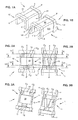
- this slider has an inverted “U” -shaped section, and comprises a base 10 to which two lateral wings 11 and 12 are attached, called “sidewalls".
- X-X ' the longitudinal axis of the slider, which corresponds to its direction of movement when it is installed on a bag with complementary profiles, has been designated.
- the flanks extend parallel to this axis.
- 110 and 111 are referenced the outer and inner faces of the sidewall 11, while the inner and outer faces of the sidewall 12 bear the references 120 and 121.
- the opposite ends of the slider 1 are shaped arches 2 and 3 of greater thickness than the rest of his body.
- this thickness could be identical over the entire range of the cursor.
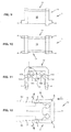
- the internal space of the slider contains means adapted to urge complementary closure profiles of a bag (marked respectively P 1 , P 2 and S at the figure 8A ), towards or away in the direction of movement of the cursor along these profiles.
- internal space is meant the space delimited by the base 10 and the flanks 11 and 12.
- these means comprise a longitudinal rib 13 which extends along the median plane X-X 'of the slider.
- This rib 13 integral with the inner face of the base 10, separates the internal space into two corridors C 1 and C 2 .
- the rib is extended downwards by an elongated central soleplate 14 which projects on either side of the rib 13 to form facets 140 and 141 for guiding a protuberance T 1 , T 2 , here in the shape of a point boom, located above an associated closure profile P 1 , P 2 (see figure 8A ).
- Each facet is turned towards the base 10.
- protuberance means any means associated with the corresponding section, which allows the cursor to cooperate with the bag.
- the inner faces 111 and 121 of the flanks 11 and 12 each bear, facing the sole 14, a projection 114, respectively 124, which is also provided with a facet 115, 125 respectively for guiding a protrusion.
- the corridors C 1 and C 2 are therefore delimited by the base 10, the rib 13 and its associated sole 14, the inner faces of the sidewalls 11 and 12 and their projections 114 and 124 associated.
- the corridors C 1 and C 2 are in the form of converged-edge grooves.
- corridors C 1 and C 2 extend only over part of the longitudinal extent of the cursor, in this case near each of its opposite ends.
- corridors C 1 and C 2 are closer to one another at a longitudinal end, so as to allow the spacing or the approximation of the profiles P 1 , P 2 as desired close or open the S bag in question. This feature is clearly visible on the Figures 2A and 3A , as well as comparing Figures 4A and 7A .
- Such a slider must be placed on a bag S whose two sails are provided with complementary closure profiles.
- the technique generally used for this purpose consists generally in deforming the slider so as to temporarily move its flanks 11 and 12 away from each other, to bring it closer to the profiles to "belt” the latter, and then to bring the flanks in their initial position.
- the bias at the opening of the flanks is made simultaneously with the push of the cursor to the profiles, which requires a perfect coordination of these operations.
- An object of the invention is to provide a device and a method of placing the cursor which simplifies the installation.
- a slider for the actuation of closure profiles in particular for a closure assembly equipping a bag, comprising a base, two sidewalls, means adapted to respectively urge said closure profiles, moving in or out according to the direction movement of the cursor along the profiles, to move the profiles between a position in closing engagement and a separate opening position, and the biasing lugs projecting on said sidewalls, in the vicinity of the end thereof opposed to said base, to open it temporarily and facilitate its engagement on said profiles when a bias is exerted on said lugs, characterized in that said means comprise means for receiving protrusions associated with said profiles.
- a bag comprising a closure system with complementary profiles, provided with a slider actuating said profiles at the opening and closing according to one of the preceding characteristics.
- closure assembly with complementary profiles, provided with a slider for actuating said profiles at the opening and closing, in accordance with one of the preceding characteristics.
- the invention relates to a device for setting up such a slider, to a bag with complementary closure profiles or to a closure assembly with complementary profiles, which comprises at least one retaining clip in a stable position of the profiles. .
- This device is remarkable in that it also comprises means for pushing a slider towards means for temporarily spacing said flanks of the slider in order to make it cooperate with said profiles, these means for spacing comprising sloping cam paths. ascending adapted to cooperate with said lugs.
- said cam paths have a longitudinal extent smaller than the stroke of said cursor, so that after having crossed the cam paths, the sides of said cursor return to their initial position.
- said cam paths are carried by said clamp.
- slider 1 Figures 1B to 8B has protruding lugs 4 projecting on the sides 11 and 12, in the vicinity of the end thereof, which is opposite the base 10, to open temporarily and facilitate its engagement on complementary profiles, associated or no to a bag, when a stress is exerted on these lugs 4.
- the lugs 4 have the shape of rectangular parallelepipeds, and are integral with the cursor. They extend on the opposite edges 112 and 122 of the flanks 11 and 12, along the axis X-X '
- the lugs 4 have, transversely, a thickness identical to that of the edges 112 and 122. However, this thickness could be smaller or thicker.
- the large external faces 110 and 120 of the flanks 11 and 12 are slightly convergent towards their free end, opposite to the base 10.
- the angle ⁇ formed by these large external faces is of the order of 4 °.
- these corridors C 1 and C 2 with convergent edges have a channel profile, such that they make it possible to ensure the guidance of the complementary profiles when the cursor is placed on the profiles. . Once the cursor is assembled, these channel profiles are then without contact, or virtually without contact with the complementary profiles.
- the facets 115 and 140 on the one hand, and 141 and 125 on the other hand form, with the associated walls of the rib 13 and flanks 11 and 12, an angle ⁇ slightly less than 90 ° .
- This angle is example of the order of 85 °.
- Such an orientation of the facets will constitute an attachment element and retaining the protuberances T 1 , T 2 associated with the profiles P 1 , P 2 of the bag S, thus improving the holding of the cursor on tearing.
- the arrangement of the lugs 4 on the end of the sidewalls 11 and 12 makes it possible to implement a much greater deformation torque than that obtained with ribs conventionally placed on the top of the slider, the lever arm relative to the hinge zone. illustrated by the reference A of the figure 12 being longer. In this way, the deformation of the flanks is easier, which simplifies the laying of the cursor on a bag.
- the bias at the opening of the sliders and the thrust can be decoupled.
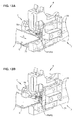
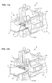
- the bag is part of a band of contiguous bags, which are moved step by step, to equip them in turn with a slider.
- the direction of scrolling is illustrated by the arrow h to Figures 13A and 13G .
- such a device 6 comprises a pair of parallel clamps 7 whose upper jaws are referenced 70, while the lower jaws are referenced 71.
- this device comprises means (not visible) slider feeding and pushing these sliders in the direction of the bag to be equipped.
- these means are disposed midway between the aforementioned jaws 7.
- a first step in this implementation, shown on the figure 13A is to open the jaws 70 and 71 of each clamp 7 so as to engage the edge of the bag S provided with complementary profiles P 1 and P 2 .
- a third step illustrated in figure 13C the cursor 1 is pushed towards the bag S, so that its biasing pins 4 engage on the paths 50 of the cams 5.
Landscapes
- Engineering & Computer Science (AREA)
- Mechanical Engineering (AREA)
- Bag Frames (AREA)
- Slide Fasteners (AREA)
Claims (4)
- Vorrichtung zum Einsetzen eines Schiebers (1) zum Betätigen von Verschlussprofilen (P1, P2), insbesondere für eine Verschlussanordnung, die an einem Beutel (S) eingerichtet ist, wobei der Schieber (1) Folgendes umfasst: eine Basis (10), zwei Flanken (11, 12) und Mittel (13), die dafür angepasst sind, die Verschlussprofile (P1, P2) zur Annäherung beziehungsweise zur Wegführung entsprechend der Bewegungsrichtung des Schiebers entlang der Profile (P1, P2) zu betätigen, um die Profile (P1, P2) zwischen einer Position im Eingriff zum Schließen und einer Position außer Eingriff zum Öffnen zu bewegen, sowie in Bewegungsrichtung hervorstehende Zapfen (4) an den Flanken (11, 12) in der Nähe von deren Ende, das der Basis (10) gegenüberliegt, um ihn behelfsweise zu öffnen und sein In-Eingriff-Bringen mit den Profilen (P1, P2) zu begünstigen, wenn eine Betätigung auf die Zapfen (4) ausgeübt wird, an einem Beutel (S) mit komplementären Verschlussprofilen (P1, P2) oder an einer Anordnung von komplementären Verschlussprofilen (P1, P2), dadurch gekennzeichnet, dass sie mindestens eine Klemme (7) zum Halten der Profile (P1, P2) in stabiler Position sowie Mittel zum Drücken eines Schiebers (1) zu den Mitteln (5) hin umfasst, um die Flanken (11, 12) des Schiebers (1) behelfsmäßig für ihr Zusammenwirken mit den Profilen (P1, P2) aufzuspreizen, wobei diese Mittel zum Aufspreizen Nockenbahnen (50) mit nach oben verlaufender Steigung umfassen, die für das Zusammenwirken mit den Zapfen (4) angepasst sind.
- Vorrichtung nach Anspruch 1, dadurch gekennzeichnet, dass die Nockenbahnen (50) eine Längsausdehnung aufweisen, die kleiner als der Hub des Schiebers (1) ist, so dass, nach dem Passieren der Nockenbahnen (50), die Flanken (11, 12) des Schiebers (1) in ihre anfängliche Position zurückkehren.
- Vorrichtung nach einem der Ansprüche 1 oder 2, dadurch gekennzeichnet, dass die Nockenbahnen (50) durch die Klemme (7) getragen werden.
- Verfahren zum Einsetzen eines Schiebers (1) an einem Beutel (S) mit komplementären Verschlussprofilen (P1, P2), wobei dieser Schieber (1) Folgendes umfasst: eine Basis (10), zwei Flanken (11, 12) und Mittel (13), die dafür angepasst sind, die Verschlussprofile (P1, P2) zur Annäherung beziehungsweise zur Wegführung entsprechend der Bewegungsrichtung des Schiebers entlang der Profile (P1, P2) zu betätigen, um die Profile (P1, P2) zwischen einer Position im Eingriff zum Schließen und einer Position außer Eingriff zum Öffnen zu bewegen, sowie hervorstehende Betätigungszapfen (4) an den Flanken (11, 12) in der Nähe von deren Ende, das der Basis (10) gegenüberliegt, um ihn behelfsweise zu öffnen und sein In-Eingriff-Bringen mit den Profilen (P1, P2) zu begünstigen, wenn eine Betätigung auf die Zapfen (4) ausgeübt wird mit Hilfe von Klemmen (7), deren Seiten, die den Backen gegenüberliegen, Nocken (5) mit nach oben verlaufender Steigung tragen, dadurch gekennzeichnet, dass es die folgenden Schritte umfasst, die darin bestehen:- die Backen (70, 71) jeder Klemme (7) zu öffnen und darin den Rand des Beutels (S), der mit komplementären Profilen versehen ist, einzuführen;- die Backen (70, 71) zusammenzudrücken, um den Beutel (S) in der Bewegung zu sperren;- den Schieber (1) in Richtung des Beutels (S) zu drücken, derart, dass die Zapfen (4) mit den Nocken (5) in Eingriff kommen und das Aufspreizen seiner Flanken (11; 12) sichergestellt wird, bis die Zapfen (4) über die Nocken (5) überstehen und nicht mehr betätigt sind, was den Eingriff des Schiebers (1) mit den Profilen bewirkt.
Applications Claiming Priority (2)
| Application Number | Priority Date | Filing Date | Title |
|---|---|---|---|
| FR0759545A FR2924312B1 (fr) | 2007-12-04 | 2007-12-04 | Curseur pourvu d'ergots de sollicitation, sachet qui en est equipe, ensemble de fermeture et dispositif pour sa mise en place. |
| PCT/EP2008/066474 WO2009071494A1 (fr) | 2007-12-04 | 2008-11-28 | Curseur pourvu d'ergots de sollicitation |
Publications (2)
| Publication Number | Publication Date |
|---|---|
| EP2214972A1 EP2214972A1 (de) | 2010-08-11 |
| EP2214972B1 true EP2214972B1 (de) | 2014-03-19 |
Family
ID=39618993
Family Applications (1)
| Application Number | Title | Priority Date | Filing Date |
|---|---|---|---|
| EP08858129.3A Not-in-force EP2214972B1 (de) | 2007-12-04 | 2008-11-28 | Schieber mit mitnehmerzapfen |
Country Status (4)
| Country | Link |
|---|---|
| US (1) | US20100310196A1 (de) |
| EP (1) | EP2214972B1 (de) |
| FR (1) | FR2924312B1 (de) |
| WO (1) | WO2009071494A1 (de) |
Families Citing this family (4)
| Publication number | Priority date | Publication date | Assignee | Title |
|---|---|---|---|---|
| FR2940751B1 (fr) | 2009-01-05 | 2011-03-11 | S2F Flexico | Curseur pour l'actionnement de profiles a barreaux rigidificateurs |
| FR2940752B1 (fr) * | 2009-01-05 | 2011-03-04 | S2F Flexico | Curseur pour l'actionnement de profiles de fermeture a lignes de pliage privilegiees |
| FR2945188B1 (fr) * | 2009-05-07 | 2011-09-30 | S2F Flexico | Machine de pose automatique de curseurs et procede associe. |
| US9216845B2 (en) * | 2012-10-26 | 2015-12-22 | Illinois Tool Works Inc. | Leak-resistant slider select zipper |
Family Cites Families (7)
| Publication number | Priority date | Publication date | Assignee | Title |
|---|---|---|---|---|
| US7454823B2 (en) * | 1999-06-10 | 2008-11-25 | The Glad Products Company | Method and apparatus for assembling slider members onto interlocking fastening strips |
| US6584666B1 (en) * | 1999-06-10 | 2003-07-01 | The Glad Products Company | Method and apparatus for assembling slider members onto interlocking fastening strips using a rail |
| US7097359B2 (en) * | 2003-02-20 | 2006-08-29 | Illinois Tool Works Inc. | Reclosable packaging having slider coupled to top of zipper |
| US7004631B1 (en) * | 2003-03-28 | 2006-02-28 | Showa Highpolymer Co., Ltd. | Portable laundry bag |
| FR2855153B1 (fr) * | 2003-05-19 | 2007-04-13 | S2F Flexico | Ensemble de fermeture pour sachet comprenant des moyens contre l'arrachement d'un curseur et sachet equipe |
| US20060171610A1 (en) * | 2005-01-31 | 2006-08-03 | Buchman James E | Internal gripping slider and method |
| US20070065051A1 (en) * | 2005-09-21 | 2007-03-22 | Eads Claude A | Infestation resistant reclosable seal |
-
2007
- 2007-12-04 FR FR0759545A patent/FR2924312B1/fr not_active Expired - Fee Related
-
2008
- 2008-11-28 EP EP08858129.3A patent/EP2214972B1/de not_active Not-in-force
- 2008-11-28 US US12/745,529 patent/US20100310196A1/en not_active Abandoned
- 2008-11-28 WO PCT/EP2008/066474 patent/WO2009071494A1/fr not_active Ceased
Also Published As
| Publication number | Publication date |
|---|---|
| EP2214972A1 (de) | 2010-08-11 |
| FR2924312B1 (fr) | 2010-01-15 |
| WO2009071494A1 (fr) | 2009-06-11 |
| US20100310196A1 (en) | 2010-12-09 |
| FR2924312A1 (fr) | 2009-06-05 |
Similar Documents
| Publication | Publication Date | Title |
|---|---|---|
| EP1251285B1 (de) | Anordnung zur Zusammenstellung zweier Karrosserieteile, Kant gegen Kant , und Karrosserie , in dieser Weise zusammengesetzt | |
| EP1464851B1 (de) | Befestigungsvorrichtung, insbesondere zum Festhalten eines Stapels von mindestens zwei Platten | |
| EP1622224A1 (de) | Elektrische Vorrichtung mit automatischer Anschlussklemme | |
| EP1263104A1 (de) | Winkelzubehörelement für Führungskanal | |
| EP0869240B1 (de) | Schlossbeschlag für Schiebetür, Schiebefenster oder ähnliches | |
| EP2214972B1 (de) | Schieber mit mitnehmerzapfen | |
| FR2682072A1 (fr) | Obturateur a souder par collage pour ouverture pratiquee dans une tole, notamment de carrosserie automobile. | |
| FR3101123A1 (fr) | Elément de blocage de cordons | |
| EP1976069A1 (de) | Steckdose mit beweglicher Abdeckung, die mit Schnappverschlüssen zum Verriegeln/Entriegeln ausgestattet ist | |
| EP2204331B1 (de) | Versteifte Schieber für einen mit Verschlussstreifen versehenen Beutel | |
| FR3008833A1 (fr) | Systeme de connecteur electrique | |
| WO2013007936A2 (fr) | Eclisse pivotante destinée au raccordement de tronçons de chemin de câbles en fils | |
| FR2901419A1 (fr) | Bloc de jonction pour conducteur electriques | |
| FR2784807A1 (fr) | Socle de prise de courant a obturateur de securite | |
| FR2940752A1 (fr) | Curseur pour l'actionnement de profiles de fermeture a lignes de pliage privilegiees | |
| EP2188809B1 (de) | Dvd-hülle | |
| EP2157592B1 (de) | Schwenkbare Gelenkeinheit | |
| EP3115515B1 (de) | Schachtabdeckung mit einem rahmen und einem paneel | |
| FR2712619A1 (fr) | Caisson modulaire pour la mise en attente de fers d'armature de béton. | |
| FR2935637A1 (fr) | Structure de montage d'une agrafe pour un instrument d'ecriture | |
| FR2895939A1 (fr) | Crochet de reception d'un tourillon d'articulation | |
| EP2099000B1 (de) | Aufbewahrungsgehäuse mit Schnellbefestigung | |
| EP4207506B1 (de) | Bausatz für einen elektrischen verbinder und elektrischer verbinder | |
| EP2391503B1 (de) | Vorrichtung und verfahren zur anordnung eines schiebers auf einem beutel mit verschlussprofilen | |
| FR2809090A3 (fr) | Boite a couvercle pivotant |
Legal Events
| Date | Code | Title | Description |
|---|---|---|---|
| PUAI | Public reference made under article 153(3) epc to a published international application that has entered the european phase |
Free format text: ORIGINAL CODE: 0009012 |
|
| 17P | Request for examination filed |
Effective date: 20100527 |
|
| AK | Designated contracting states |
Kind code of ref document: A1 Designated state(s): AT BE BG CH CY CZ DE DK EE ES FI FR GB GR HR HU IE IS IT LI LT LU LV MC MT NL NO PL PT RO SE SI SK TR |
|
| AX | Request for extension of the european patent |
Extension state: AL BA MK RS |
|
| RIN1 | Information on inventor provided before grant (corrected) |
Inventor name: ROGER, ANTONY |
|
| DAX | Request for extension of the european patent (deleted) | ||
| GRAP | Despatch of communication of intention to grant a patent |
Free format text: ORIGINAL CODE: EPIDOSNIGR1 |
|
| INTG | Intention to grant announced |
Effective date: 20130910 |
|
| GRAS | Grant fee paid |
Free format text: ORIGINAL CODE: EPIDOSNIGR3 |
|
| GRAA | (expected) grant |
Free format text: ORIGINAL CODE: 0009210 |
|
| AK | Designated contracting states |
Kind code of ref document: B1 Designated state(s): AT BE BG CH CY CZ DE DK EE ES FI FR GB GR HR HU IE IS IT LI LT LU LV MC MT NL NO PL PT RO SE SI SK TR |
|
| REG | Reference to a national code |
Ref country code: GB Ref legal event code: FG4D Free format text: NOT ENGLISH |
|
| REG | Reference to a national code |
Ref country code: CH Ref legal event code: EP |
|
| REG | Reference to a national code |
Ref country code: IE Ref legal event code: FG4D Free format text: LANGUAGE OF EP DOCUMENT: FRENCH |
|
| REG | Reference to a national code |
Ref country code: AT Ref legal event code: REF Ref document number: 657508 Country of ref document: AT Kind code of ref document: T Effective date: 20140415 |
|
| REG | Reference to a national code |
Ref country code: DE Ref legal event code: R096 Ref document number: 602008031016 Country of ref document: DE Effective date: 20140430 |
|
| PG25 | Lapsed in a contracting state [announced via postgrant information from national office to epo] |
Ref country code: NO Free format text: LAPSE BECAUSE OF FAILURE TO SUBMIT A TRANSLATION OF THE DESCRIPTION OR TO PAY THE FEE WITHIN THE PRESCRIBED TIME-LIMIT Effective date: 20140619 Ref country code: LT Free format text: LAPSE BECAUSE OF FAILURE TO SUBMIT A TRANSLATION OF THE DESCRIPTION OR TO PAY THE FEE WITHIN THE PRESCRIBED TIME-LIMIT Effective date: 20140319 |
|
| REG | Reference to a national code |
Ref country code: NL Ref legal event code: VDEP Effective date: 20140319 |
|
| REG | Reference to a national code |
Ref country code: AT Ref legal event code: MK05 Ref document number: 657508 Country of ref document: AT Kind code of ref document: T Effective date: 20140319 |
|
| REG | Reference to a national code |
Ref country code: LT Ref legal event code: MG4D |
|
| PG25 | Lapsed in a contracting state [announced via postgrant information from national office to epo] |
Ref country code: SE Free format text: LAPSE BECAUSE OF FAILURE TO SUBMIT A TRANSLATION OF THE DESCRIPTION OR TO PAY THE FEE WITHIN THE PRESCRIBED TIME-LIMIT Effective date: 20140319 Ref country code: CY Free format text: LAPSE BECAUSE OF FAILURE TO SUBMIT A TRANSLATION OF THE DESCRIPTION OR TO PAY THE FEE WITHIN THE PRESCRIBED TIME-LIMIT Effective date: 20140319 Ref country code: FI Free format text: LAPSE BECAUSE OF FAILURE TO SUBMIT A TRANSLATION OF THE DESCRIPTION OR TO PAY THE FEE WITHIN THE PRESCRIBED TIME-LIMIT Effective date: 20140319 |
|
| PG25 | Lapsed in a contracting state [announced via postgrant information from national office to epo] |
Ref country code: HR Free format text: LAPSE BECAUSE OF FAILURE TO SUBMIT A TRANSLATION OF THE DESCRIPTION OR TO PAY THE FEE WITHIN THE PRESCRIBED TIME-LIMIT Effective date: 20140319 Ref country code: LV Free format text: LAPSE BECAUSE OF FAILURE TO SUBMIT A TRANSLATION OF THE DESCRIPTION OR TO PAY THE FEE WITHIN THE PRESCRIBED TIME-LIMIT Effective date: 20140319 |
|
| PG25 | Lapsed in a contracting state [announced via postgrant information from national office to epo] |
Ref country code: IS Free format text: LAPSE BECAUSE OF FAILURE TO SUBMIT A TRANSLATION OF THE DESCRIPTION OR TO PAY THE FEE WITHIN THE PRESCRIBED TIME-LIMIT Effective date: 20140719 Ref country code: NL Free format text: LAPSE BECAUSE OF FAILURE TO SUBMIT A TRANSLATION OF THE DESCRIPTION OR TO PAY THE FEE WITHIN THE PRESCRIBED TIME-LIMIT Effective date: 20140319 Ref country code: BG Free format text: LAPSE BECAUSE OF FAILURE TO SUBMIT A TRANSLATION OF THE DESCRIPTION OR TO PAY THE FEE WITHIN THE PRESCRIBED TIME-LIMIT Effective date: 20140619 Ref country code: CZ Free format text: LAPSE BECAUSE OF FAILURE TO SUBMIT A TRANSLATION OF THE DESCRIPTION OR TO PAY THE FEE WITHIN THE PRESCRIBED TIME-LIMIT Effective date: 20140319 Ref country code: RO Free format text: LAPSE BECAUSE OF FAILURE TO SUBMIT A TRANSLATION OF THE DESCRIPTION OR TO PAY THE FEE WITHIN THE PRESCRIBED TIME-LIMIT Effective date: 20140319 Ref country code: EE Free format text: LAPSE BECAUSE OF FAILURE TO SUBMIT A TRANSLATION OF THE DESCRIPTION OR TO PAY THE FEE WITHIN THE PRESCRIBED TIME-LIMIT Effective date: 20140319 |
|
| PG25 | Lapsed in a contracting state [announced via postgrant information from national office to epo] |
Ref country code: PL Free format text: LAPSE BECAUSE OF FAILURE TO SUBMIT A TRANSLATION OF THE DESCRIPTION OR TO PAY THE FEE WITHIN THE PRESCRIBED TIME-LIMIT Effective date: 20140319 Ref country code: AT Free format text: LAPSE BECAUSE OF FAILURE TO SUBMIT A TRANSLATION OF THE DESCRIPTION OR TO PAY THE FEE WITHIN THE PRESCRIBED TIME-LIMIT Effective date: 20140319 Ref country code: SK Free format text: LAPSE BECAUSE OF FAILURE TO SUBMIT A TRANSLATION OF THE DESCRIPTION OR TO PAY THE FEE WITHIN THE PRESCRIBED TIME-LIMIT Effective date: 20140319 Ref country code: ES Free format text: LAPSE BECAUSE OF FAILURE TO SUBMIT A TRANSLATION OF THE DESCRIPTION OR TO PAY THE FEE WITHIN THE PRESCRIBED TIME-LIMIT Effective date: 20140319 |
|
| REG | Reference to a national code |
Ref country code: DE Ref legal event code: R097 Ref document number: 602008031016 Country of ref document: DE |
|
| PG25 | Lapsed in a contracting state [announced via postgrant information from national office to epo] |
Ref country code: PT Free format text: LAPSE BECAUSE OF FAILURE TO SUBMIT A TRANSLATION OF THE DESCRIPTION OR TO PAY THE FEE WITHIN THE PRESCRIBED TIME-LIMIT Effective date: 20140721 |
|
| PLBE | No opposition filed within time limit |
Free format text: ORIGINAL CODE: 0009261 |
|
| STAA | Information on the status of an ep patent application or granted ep patent |
Free format text: STATUS: NO OPPOSITION FILED WITHIN TIME LIMIT |
|
| PG25 | Lapsed in a contracting state [announced via postgrant information from national office to epo] |
Ref country code: DK Free format text: LAPSE BECAUSE OF FAILURE TO SUBMIT A TRANSLATION OF THE DESCRIPTION OR TO PAY THE FEE WITHIN THE PRESCRIBED TIME-LIMIT Effective date: 20140319 |
|
| 26N | No opposition filed |
Effective date: 20141222 |
|
| PG25 | Lapsed in a contracting state [announced via postgrant information from national office to epo] |
Ref country code: IT Free format text: LAPSE BECAUSE OF FAILURE TO SUBMIT A TRANSLATION OF THE DESCRIPTION OR TO PAY THE FEE WITHIN THE PRESCRIBED TIME-LIMIT Effective date: 20140319 |
|
| REG | Reference to a national code |
Ref country code: DE Ref legal event code: R097 Ref document number: 602008031016 Country of ref document: DE Effective date: 20141222 |
|
| PG25 | Lapsed in a contracting state [announced via postgrant information from national office to epo] |
Ref country code: BE Free format text: LAPSE BECAUSE OF NON-PAYMENT OF DUE FEES Effective date: 20141130 Ref country code: LU Free format text: LAPSE BECAUSE OF FAILURE TO SUBMIT A TRANSLATION OF THE DESCRIPTION OR TO PAY THE FEE WITHIN THE PRESCRIBED TIME-LIMIT Effective date: 20141128 Ref country code: MC Free format text: LAPSE BECAUSE OF FAILURE TO SUBMIT A TRANSLATION OF THE DESCRIPTION OR TO PAY THE FEE WITHIN THE PRESCRIBED TIME-LIMIT Effective date: 20140319 |
|
| REG | Reference to a national code |
Ref country code: CH Ref legal event code: PL |
|
| REG | Reference to a national code |
Ref country code: DE Ref legal event code: R082 Ref document number: 602008031016 Country of ref document: DE Representative=s name: HOEGER, STELLRECHT & PARTNER PATENTANWAELTE MB, DE |
|
| PG25 | Lapsed in a contracting state [announced via postgrant information from national office to epo] |
Ref country code: LI Free format text: LAPSE BECAUSE OF NON-PAYMENT OF DUE FEES Effective date: 20141130 Ref country code: SI Free format text: LAPSE BECAUSE OF FAILURE TO SUBMIT A TRANSLATION OF THE DESCRIPTION OR TO PAY THE FEE WITHIN THE PRESCRIBED TIME-LIMIT Effective date: 20140319 Ref country code: CH Free format text: LAPSE BECAUSE OF NON-PAYMENT OF DUE FEES Effective date: 20141130 |
|
| REG | Reference to a national code |
Ref country code: IE Ref legal event code: MM4A |
|
| PG25 | Lapsed in a contracting state [announced via postgrant information from national office to epo] |
Ref country code: IE Free format text: LAPSE BECAUSE OF NON-PAYMENT OF DUE FEES Effective date: 20141128 |
|
| REG | Reference to a national code |
Ref country code: FR Ref legal event code: PLFP Year of fee payment: 8 |
|
| PG25 | Lapsed in a contracting state [announced via postgrant information from national office to epo] |
Ref country code: GR Free format text: LAPSE BECAUSE OF FAILURE TO SUBMIT A TRANSLATION OF THE DESCRIPTION OR TO PAY THE FEE WITHIN THE PRESCRIBED TIME-LIMIT Effective date: 20140620 |
|
| PG25 | Lapsed in a contracting state [announced via postgrant information from national office to epo] |
Ref country code: HU Free format text: LAPSE BECAUSE OF FAILURE TO SUBMIT A TRANSLATION OF THE DESCRIPTION OR TO PAY THE FEE WITHIN THE PRESCRIBED TIME-LIMIT; INVALID AB INITIO Effective date: 20081128 Ref country code: TR Free format text: LAPSE BECAUSE OF FAILURE TO SUBMIT A TRANSLATION OF THE DESCRIPTION OR TO PAY THE FEE WITHIN THE PRESCRIBED TIME-LIMIT Effective date: 20140319 Ref country code: MT Free format text: LAPSE BECAUSE OF FAILURE TO SUBMIT A TRANSLATION OF THE DESCRIPTION OR TO PAY THE FEE WITHIN THE PRESCRIBED TIME-LIMIT Effective date: 20140319 |
|
| REG | Reference to a national code |
Ref country code: FR Ref legal event code: PLFP Year of fee payment: 9 |
|
| REG | Reference to a national code |
Ref country code: FR Ref legal event code: PLFP Year of fee payment: 10 |
|
| REG | Reference to a national code |
Ref country code: DE Ref legal event code: R082 Ref document number: 602008031016 Country of ref document: DE Representative=s name: HOEGER, STELLRECHT & PARTNER PATENTANWAELTE MB, DE |
|
| PGFP | Annual fee paid to national office [announced via postgrant information from national office to epo] |
Ref country code: GB Payment date: 20201118 Year of fee payment: 13 Ref country code: DE Payment date: 20201109 Year of fee payment: 13 Ref country code: FR Payment date: 20201110 Year of fee payment: 13 |
|
| REG | Reference to a national code |
Ref country code: DE Ref legal event code: R119 Ref document number: 602008031016 Country of ref document: DE |
|
| GBPC | Gb: european patent ceased through non-payment of renewal fee |
Effective date: 20211128 |
|
| PG25 | Lapsed in a contracting state [announced via postgrant information from national office to epo] |
Ref country code: GB Free format text: LAPSE BECAUSE OF NON-PAYMENT OF DUE FEES Effective date: 20211128 Ref country code: DE Free format text: LAPSE BECAUSE OF NON-PAYMENT OF DUE FEES Effective date: 20220601 |
|
| PG25 | Lapsed in a contracting state [announced via postgrant information from national office to epo] |
Ref country code: FR Free format text: LAPSE BECAUSE OF NON-PAYMENT OF DUE FEES Effective date: 20211130 |