EP2214972B1 - Slider with camming spigots - Google Patents
Slider with camming spigots Download PDFInfo
- Publication number
- EP2214972B1 EP2214972B1 EP08858129.3A EP08858129A EP2214972B1 EP 2214972 B1 EP2214972 B1 EP 2214972B1 EP 08858129 A EP08858129 A EP 08858129A EP 2214972 B1 EP2214972 B1 EP 2214972B1
- Authority
- EP
- European Patent Office
- Prior art keywords
- profiles
- slider
- flanks
- bag
- spigots
- Prior art date
- Legal status (The legal status is an assumption and is not a legal conclusion. Google has not performed a legal analysis and makes no representation as to the accuracy of the status listed.)
- Not-in-force
Links
Images


Classifications
-
- B—PERFORMING OPERATIONS; TRANSPORTING
- B65—CONVEYING; PACKING; STORING; HANDLING THIN OR FILAMENTARY MATERIAL
- B65D—CONTAINERS FOR STORAGE OR TRANSPORT OF ARTICLES OR MATERIALS, e.g. BAGS, BARRELS, BOTTLES, BOXES, CANS, CARTONS, CRATES, DRUMS, JARS, TANKS, HOPPERS, FORWARDING CONTAINERS; ACCESSORIES, CLOSURES, OR FITTINGS THEREFOR; PACKAGING ELEMENTS; PACKAGES
- B65D33/00—Details of, or accessories for, sacks or bags
- B65D33/16—End- or aperture-closing arrangements or devices
- B65D33/25—Riveting; Dovetailing; Screwing; using press buttons or slide fasteners
- B65D33/2508—Riveting; Dovetailing; Screwing; using press buttons or slide fasteners using slide fasteners with interlocking members having a substantially uniform section throughout the length of the fastener; Sliders therefor
- B65D33/2566—Riveting; Dovetailing; Screwing; using press buttons or slide fasteners using slide fasteners with interlocking members having a substantially uniform section throughout the length of the fastener; Sliders therefor using two or more independently operable slide fasteners
-
- B—PERFORMING OPERATIONS; TRANSPORTING
- B31—MAKING ARTICLES OF PAPER, CARDBOARD OR MATERIAL WORKED IN A MANNER ANALOGOUS TO PAPER; WORKING PAPER, CARDBOARD OR MATERIAL WORKED IN A MANNER ANALOGOUS TO PAPER
- B31B—MAKING CONTAINERS OF PAPER, CARDBOARD OR MATERIAL WORKED IN A MANNER ANALOGOUS TO PAPER
- B31B70/00—Making flexible containers, e.g. envelopes or bags
- B31B70/74—Auxiliary operations
- B31B70/81—Forming or attaching accessories, e.g. opening devices, closures or tear strings
- B31B70/813—Applying closures
- B31B70/8131—Making bags having interengaging closure elements
- B31B70/8132—Applying the closure elements in the machine direction
Definitions
- the present invention relates to the field of bags provided with complementary closure profiles actuated by a slider.
- It relates more specifically to a device and a method for the establishment of a slider provided with biasing pins.
- Such a slider is made of molded plastic and has a generally known structure.
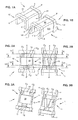
- this slider has an inverted “U” -shaped section, and comprises a base 10 to which two lateral wings 11 and 12 are attached, called “sidewalls".
- X-X ' the longitudinal axis of the slider, which corresponds to its direction of movement when it is installed on a bag with complementary profiles, has been designated.
- the flanks extend parallel to this axis.
- 110 and 111 are referenced the outer and inner faces of the sidewall 11, while the inner and outer faces of the sidewall 12 bear the references 120 and 121.
- the opposite ends of the slider 1 are shaped arches 2 and 3 of greater thickness than the rest of his body.
- this thickness could be identical over the entire range of the cursor.
- the internal space of the slider contains means adapted to urge complementary closure profiles of a bag (marked respectively P 1 , P 2 and S at the figure 8A ), towards or away in the direction of movement of the cursor along these profiles.
- internal space is meant the space delimited by the base 10 and the flanks 11 and 12.
- these means comprise a longitudinal rib 13 which extends along the median plane X-X 'of the slider.
- This rib 13 integral with the inner face of the base 10, separates the internal space into two corridors C 1 and C 2 .
- the rib is extended downwards by an elongated central soleplate 14 which projects on either side of the rib 13 to form facets 140 and 141 for guiding a protuberance T 1 , T 2 , here in the shape of a point boom, located above an associated closure profile P 1 , P 2 (see figure 8A ).
- Each facet is turned towards the base 10.
- protuberance means any means associated with the corresponding section, which allows the cursor to cooperate with the bag.
- the inner faces 111 and 121 of the flanks 11 and 12 each bear, facing the sole 14, a projection 114, respectively 124, which is also provided with a facet 115, 125 respectively for guiding a protrusion.
- the corridors C 1 and C 2 are therefore delimited by the base 10, the rib 13 and its associated sole 14, the inner faces of the sidewalls 11 and 12 and their projections 114 and 124 associated.
- the corridors C 1 and C 2 are in the form of converged-edge grooves.
- corridors C 1 and C 2 extend only over part of the longitudinal extent of the cursor, in this case near each of its opposite ends.
- corridors C 1 and C 2 are closer to one another at a longitudinal end, so as to allow the spacing or the approximation of the profiles P 1 , P 2 as desired close or open the S bag in question. This feature is clearly visible on the Figures 2A and 3A , as well as comparing Figures 4A and 7A .
- Such a slider must be placed on a bag S whose two sails are provided with complementary closure profiles.
- the technique generally used for this purpose consists generally in deforming the slider so as to temporarily move its flanks 11 and 12 away from each other, to bring it closer to the profiles to "belt” the latter, and then to bring the flanks in their initial position.
- the bias at the opening of the flanks is made simultaneously with the push of the cursor to the profiles, which requires a perfect coordination of these operations.
- An object of the invention is to provide a device and a method of placing the cursor which simplifies the installation.
- a slider for the actuation of closure profiles in particular for a closure assembly equipping a bag, comprising a base, two sidewalls, means adapted to respectively urge said closure profiles, moving in or out according to the direction movement of the cursor along the profiles, to move the profiles between a position in closing engagement and a separate opening position, and the biasing lugs projecting on said sidewalls, in the vicinity of the end thereof opposed to said base, to open it temporarily and facilitate its engagement on said profiles when a bias is exerted on said lugs, characterized in that said means comprise means for receiving protrusions associated with said profiles.
- a bag comprising a closure system with complementary profiles, provided with a slider actuating said profiles at the opening and closing according to one of the preceding characteristics.
- closure assembly with complementary profiles, provided with a slider for actuating said profiles at the opening and closing, in accordance with one of the preceding characteristics.
- the invention relates to a device for setting up such a slider, to a bag with complementary closure profiles or to a closure assembly with complementary profiles, which comprises at least one retaining clip in a stable position of the profiles. .
- This device is remarkable in that it also comprises means for pushing a slider towards means for temporarily spacing said flanks of the slider in order to make it cooperate with said profiles, these means for spacing comprising sloping cam paths. ascending adapted to cooperate with said lugs.
- said cam paths have a longitudinal extent smaller than the stroke of said cursor, so that after having crossed the cam paths, the sides of said cursor return to their initial position.
- said cam paths are carried by said clamp.
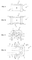
- slider 1 Figures 1B to 8B has protruding lugs 4 projecting on the sides 11 and 12, in the vicinity of the end thereof, which is opposite the base 10, to open temporarily and facilitate its engagement on complementary profiles, associated or no to a bag, when a stress is exerted on these lugs 4.
- the lugs 4 have the shape of rectangular parallelepipeds, and are integral with the cursor. They extend on the opposite edges 112 and 122 of the flanks 11 and 12, along the axis X-X '
- the lugs 4 have, transversely, a thickness identical to that of the edges 112 and 122. However, this thickness could be smaller or thicker.
- the large external faces 110 and 120 of the flanks 11 and 12 are slightly convergent towards their free end, opposite to the base 10.
- the angle ⁇ formed by these large external faces is of the order of 4 °.
- these corridors C 1 and C 2 with convergent edges have a channel profile, such that they make it possible to ensure the guidance of the complementary profiles when the cursor is placed on the profiles. . Once the cursor is assembled, these channel profiles are then without contact, or virtually without contact with the complementary profiles.
- the facets 115 and 140 on the one hand, and 141 and 125 on the other hand form, with the associated walls of the rib 13 and flanks 11 and 12, an angle ⁇ slightly less than 90 ° .
- This angle is example of the order of 85 °.
- Such an orientation of the facets will constitute an attachment element and retaining the protuberances T 1 , T 2 associated with the profiles P 1 , P 2 of the bag S, thus improving the holding of the cursor on tearing.
- the arrangement of the lugs 4 on the end of the sidewalls 11 and 12 makes it possible to implement a much greater deformation torque than that obtained with ribs conventionally placed on the top of the slider, the lever arm relative to the hinge zone. illustrated by the reference A of the figure 12 being longer. In this way, the deformation of the flanks is easier, which simplifies the laying of the cursor on a bag.
- the bias at the opening of the sliders and the thrust can be decoupled.
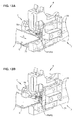
- the bag is part of a band of contiguous bags, which are moved step by step, to equip them in turn with a slider.
- the direction of scrolling is illustrated by the arrow h to Figures 13A and 13G .
- such a device 6 comprises a pair of parallel clamps 7 whose upper jaws are referenced 70, while the lower jaws are referenced 71.
- this device comprises means (not visible) slider feeding and pushing these sliders in the direction of the bag to be equipped.
- these means are disposed midway between the aforementioned jaws 7.
- a first step in this implementation, shown on the figure 13A is to open the jaws 70 and 71 of each clamp 7 so as to engage the edge of the bag S provided with complementary profiles P 1 and P 2 .
- a third step illustrated in figure 13C the cursor 1 is pushed towards the bag S, so that its biasing pins 4 engage on the paths 50 of the cams 5.
Landscapes
- Engineering & Computer Science (AREA)
- Mechanical Engineering (AREA)
- Bag Frames (AREA)
- Slide Fasteners (AREA)
Description
La présente invention concerne le domaine des sachets pourvus de profilés complémentaires de fermeture, actionnés par un curseur.The present invention relates to the field of bags provided with complementary closure profiles actuated by a slider.
Elle concerne plus précisément un dispositif et un procédé pour la mise en place d'un curseur pourvu d'ergots de sollicitation.It relates more specifically to a device and a method for the establishment of a slider provided with biasing pins.
De nombreux sachets à profilés complémentaires de fermeture équipés de curseurs ont déjà été proposés.Many bags with complementary closure profiles equipped with sliders have already been proposed.
Certaines des figures annexées représentent un exemple de curseur conforme à l'état de la technique.Some of the appended figures represent an example of slider according to the state of the art.
Plus précisément :
- la
figure 1 A est une vue en perspective d'un tel curseur; - la
figure 2A est une vue de dessous de ce curseur; - la
figure 3A est une vue analogue à la précédente en légère perspective ; - les
figures 4A, 5A, 6A et 7A sont respectivement des vues en coupe du curseur de lafigure 2A , selon les plans IV-IV, V-V, VI-VI et VII-VII de cette figure ; - la
figure 8A est une vue en bout du curseur de lafigure 1 A .
- the
figure 1 A is a perspective view of such a slider; - the
Figure 2A is a view from below of this slider; - the
figure 3A is a view similar to the preceding in slight perspective; - the
FIGS. 4A, 5A, 6A and 7A are respectively sectional views of the cursor of theFigure 2A according to plans IV-IV, VV, VI-VI and VII-VII of this figure; - the
figure 8A is an end view of the slider of thefigure 1 A .
Sur ces figures, les profilés avec lesquels le curseur est destiné à coopérer ont été représentés uniquement à la
Un tel curseur est réalisé en matière plastique moulée et présente une structure généralement connue.Such a slider is made of molded plastic and has a generally known structure.
Plus précisément, ce curseur a une section en forme de "U" inversé, et comporte une base 10 à laquelle se rattachent deux ailes latérales 11 et 12 appelées "flancs". On a désigné X-X', l'axe longitudinal du curseur, qui correspond à sa direction de déplacement quand il est installé sur un sachet à profilés complémentaires. Les flancs s'étendent parallèlement à cet axe.More precisely, this slider has an inverted "U" -shaped section, and comprises a
Sur les figures précitées, on a référencé 110 et 111 les faces externe et interne du flanc 11, tandis que les faces interne et externe du flanc 12 portent les références 120 et 121.In the aforementioned figures, 110 and 111 are referenced the outer and inner faces of the
Essentiellement pour des raisons de rigidité, les extrémités opposées du curseur 1 sont conformées en arches 2 et 3 d'épaisseur plus importante que le reste de son corps.Essentially for reasons of rigidity, the opposite ends of the
Bien entendu, dans un mode de réalisation non représenté, cette épaisseur pourrait être identique sur toute l'étendue du curseur.Of course, in an embodiment not shown, this thickness could be identical over the entire range of the cursor.
De manière bien connue en soi, l'espace interne du curseur renferme des moyens adaptés pour solliciter des profilés complémentaires de fermeture d'un sachet (repérés respectivement P1, P2 et S à la
En l'occurrence, ces moyens comprennent une nervure longitudinale 13 qui s'étend selon le plan médian X-X' du curseur.In this case, these means comprise a
Cette nervure 13, venue de matière avec la face interne de la base 10, sépare l'espace interne en deux couloirs C1 et C2.This
Ainsi que le montrent plus spécifiquement les
Par ailleurs, les faces internes 111 et 121 des flancs 11 et 12 portent chacune, en regard de la semelle 14, une saillie 114, respectivement 124, qui est également pourvue d'une facette 115, respectivement 125 de guidage d'une protubérance.Furthermore, the
Les couloirs C1 et C2 sont donc délimités par la base 10, la nervure 13 et sa semelle associée 14, les faces internes des flancs 11 et 12 et leurs saillies 114 et 124 associées. En d'autres termes, les couloirs C1 et C2 ont la forme de gorges à bords convergents.The corridors C 1 and C 2 are therefore delimited by the
Ainsi que cela apparaît aux
Par ailleurs, les couloirs C1 et C2 sont plus proches l'un de l'autre d'une extrémité longitudinale, de manière à permettre l'écartement, ou le rapprochement des profilés P1, P2 selon que l'on souhaite fermer ou ouvrir le sachet S en question. Cette particularité est clairement visible sur les
Telle est la structure d'un curseur conforme à l'état de la technique.This is the structure of a slider according to the state of the art.
Un tel curseur doit donc être mis en place sur un sachet S dont les deux voiles sont pourvus de profilés de fermeture complémentaires.Such a slider must be placed on a bag S whose two sails are provided with complementary closure profiles.
La technique généralement mise en oeuvre pour ce faire consiste globalement à déformer le curseur de manière à écarter momentanément ses flancs 11 et 12 l'un de l'autre, à le rapprocher des profilés pour "ceinturer" ces derniers, puis à ramener les flancs dans leur position initiale.The technique generally used for this purpose consists generally in deforming the slider so as to temporarily move its
Dans la demande
Cette solution ne donne cependant pas totalement satisfaction lorsque le curseur possède une épaisseur importante.This solution does not give complete satisfaction when the slider has a significant thickness.
En effet, dans ces conditions, le bras de levier généré est peu important, et les flancs ne se déforment pas aussi bien qu'on pourrait le souhaiter.Indeed, under these conditions, the lever arm generated is not important, and the sides do not deform as well as one might wish.
De plus, la sollicitation à l'ouverture des flancs est faite simultanément à la poussée du curseur vers les profilés, ce qui nécessite une parfaite coordination de ces opérations.In addition, the bias at the opening of the flanks is made simultaneously with the push of the cursor to the profiles, which requires a perfect coordination of these operations.
Dans le document
Un objectif de l'invention est de proposer un dispositif et un procédé de mise en place du curseur qui en simplifie la pose.An object of the invention is to provide a device and a method of placing the cursor which simplifies the installation.
Il est décrit un curseur pour l'actionnement de profilés de fermeture, notamment pour un ensemble de fermeture équipant un sachet, comprenant une base, deux flancs, des moyens adaptés pour solliciter respectivement lesdits profilés de fermeture, en rapprochement ou en éloignement selon le sens de déplacement du curseur le long des profilés, pour déplacer les profilés entre une position en prise de fermeture et une position séparée d'ouverture, ainsi que des ergots de sollicitation en saillie sur lesdits flancs, au voisinage de l'extrémité de ceux-ci opposée à ladite base, pour l'ouvrir provisoirement et faciliter son engagement sur lesdits profilés lorsqu'une sollicitation est exercée sur lesdits ergots, caractérisé par le fait que lesdits moyens comprennent des moyens de réception de protubérances associées auxdits profilés.It is described a slider for the actuation of closure profiles, in particular for a closure assembly equipping a bag, comprising a base, two sidewalls, means adapted to respectively urge said closure profiles, moving in or out according to the direction movement of the cursor along the profiles, to move the profiles between a position in closing engagement and a separate opening position, and the biasing lugs projecting on said sidewalls, in the vicinity of the end thereof opposed to said base, to open it temporarily and facilitate its engagement on said profiles when a bias is exerted on said lugs, characterized in that said means comprise means for receiving protrusions associated with said profiles.
Selon d'autres caractéristiques avantageuses et non limitatives de ce curseur :
- les grandes faces externes desdits flancs sont légèrement convergentes en direction de leur extrémité opposée à la dite base ;
- l'angle α formé par lesdites grandes faces externes est de l'ordre de 4°;
- l'angle ß formé par ladite facette et la paroi associée de ladite nervure est inférieur à 90°;
- l'angle ß formé par ladite facette et la face interne dudit flanc est inférieur à 90° ;
- ledit angle ß est de l'ordre de 85°;
- une partie intermédiaire desdits couloirs présente un profil tel qu'ils assurent le guidage desdits profilés lors de sa mise en place du curseur sur les profilés, de sorte qu'une fois le curseur assemblé, ces profils en canal sont alors sans contact ou pratiquement sans contact avec ceux-ci;
- the large outer faces of said flanks are slightly convergent toward their opposite end to said base;
- the angle α formed by said large external faces is of the order of 4 °;
- the angle β formed by said facet and the associated wall of said rib is less than 90 °;
- the angle β formed by said facet and the inner face of said flank is less than 90 °;
- said angle β is of the order of 85 °;
- an intermediate portion of said lanes has a profile such that they ensure the guiding of said profiles during its introduction of the cursor on the profiles, so that once the cursor assembled, these channel profiles are then without contact or virtually without contact with them;
Il est décrit également un sachet comprenant un ensemble de fermeture à profilés complémentaires, pourvu d'un curseur d'actionnement desdits profilés à l'ouverture et à la fermeture conforme à l'une des caractéristiques précédentes.It is also described a bag comprising a closure system with complementary profiles, provided with a slider actuating said profiles at the opening and closing according to one of the preceding characteristics.
Il est décrit aussi un ensemble de fermeture à profilés complémentaires, pourvu d'un curseur d'actionnement desdits profilés à l'ouverture et à la fermeture, conforme à l'une des caractéristiques précédentes.There is also described a closure assembly with complementary profiles, provided with a slider for actuating said profiles at the opening and closing, in accordance with one of the preceding characteristics.
L'invention se rapporte à un dispositif pour la mise en place d'un tel curseur, sur un sachet à profilés de fermeture complémentaires ou sur un ensemble de fermeture à profilés complémentaires, qui comprend au moins une pince de retenue en position stable des profilés.The invention relates to a device for setting up such a slider, to a bag with complementary closure profiles or to a closure assembly with complementary profiles, which comprises at least one retaining clip in a stable position of the profiles. .
Ce dispositif est remarquable en ce qu'il comporte également des moyens de poussée d'un curseur vers des moyens pour écarter provisoirement lesdits flancs du curseur en vue de le faire coopérer avec lesdits profilés, ces moyens pour écarter comprenant des chemins de came à pente ascendante apte à coopérer avec lesdits ergots.This device is remarkable in that it also comprises means for pushing a slider towards means for temporarily spacing said flanks of the slider in order to make it cooperate with said profiles, these means for spacing comprising sloping cam paths. ascending adapted to cooperate with said lugs.
Avantageusement, lesdits chemins de came présentent une étendue longitudinale inférieure à la course dudit curseur, de sorte qu'après avoir franchi les chemins de came, les flancs dudit curseur reviennent vers leur position initiale.Advantageously, said cam paths have a longitudinal extent smaller than the stroke of said cursor, so that after having crossed the cam paths, the sides of said cursor return to their initial position.
Préférentiellement, lesdits chemins de cames sont portés par ladite pince.Preferably, said cam paths are carried by said clamp.
Enfin l'invention concerne un procédé de mise en place d'un tel curseur sur un sachet, au moyen de pinces dont les faces en regard portent des cames à pente ascendante. Ce procédé se caractérise en ce qu'il comprend les étapes qui consistent à :
- ouvrir les mâchoires de chaque pince et y engager le bord du sachet pourvu de profilés complémentaires ;
- resserrer les mâchoires pour immobiliser le sachet;
- pousser ledit curseur en direction du sachet, de manière à ce que ses ergots s'engagent sur les cames et assurent l'écartement de ses flancs, jusqu'à ce que les ergots dépassent lesdites cames et ne soient plus sollicités, ce qui provoque l'engagement du curseur sur les profilés.
- open the jaws of each clamp and engage the edge of the bag provided with complementary profiles;
- tighten the jaws to immobilize the bag;
- pushing said slider towards the bag, so that its lugs engage on the cams and ensure the spacing of its flanks, until the pins protrude from said cams and are no longer stressed, which causes the Cursor engagement on the profiles.
D'autres caractéristiques et avantages de la présente invention apparaîtront à la lecture de la description qui va suivre d'un mode de réalisation préférentiel. Cette description sera donnée en référence aux dessins annexés, et plus spécifiquement en se rapportant aux
- la
figure 9 est une vue de côté d'un curseur selon l'invention ; - la
figure 10 est une vue de dessus du curseur de lafigure 9 ; - la
figure 11 est une vue en bout de ce curseur ; - la
figure 12 est un schéma montrant, selon une vue en bout, le curseur des figures précédentes, en relation avec des chemins de came qui vont permettre d'en écarter les flancs ; - les
figures 13A à 13G sont des schémas montrant un dispositif pour la mise en place d'un curseur tel que celui des figures précédentes, sur un sachet à profilés de fermeture complémentaires, ces différentes figures illustrant les étapes principales de mise en place.
- the
figure 9 is a side view of a slider according to the invention; - the
figure 10 is a top view of the slider of thefigure 9 ; - the
figure 11 is an end view of this slider; - the
figure 12 is a diagram showing, in an end view, the cursor of the previous figures, in relation to cam paths that will allow to move the flanks; - the
Figures 13A to 13G are diagrams showing a device for the implementation of a slider such as that of the previous figures, on a bag with complementary closure profiles, these different figures illustrating the main steps of implementation.
L'exemple de curseur, qui est représenté sur les figures annoncées ci-dessus, présente sensiblement la même structure générale que celui qui a été décrit précédemment, en référence à l'état de la technique (
Les références identiques à celles déjà utilisées désignent les mêmes éléments.References identical to those already used designate the same elements.
Comme annoncé, le curseur 1 des
La manière dont cette sollicitation est exercée sera décrite plus loin dans la description.The manner in which this solicitation is exercised will be described later in the description.
Plus précisément, sur les figures annexées, les ergots 4 ont la forme de parallélépipèdes rectangles, et sont venus de matière avec le curseur. Ils s'étendent sur les chants opposés 112 et 122 des flancs 11 et 12, selon l'axe X-X'More specifically, in the accompanying figures, the
Il est prévu un ergot sur le chant de chaque flanc. Et ces ergots sont placés au voisinage de l'extrémité libre des flancs.There is a lug on the edge of each side. And these lugs are placed in the vicinity of the free end of the flanks.
Enfin, et ainsi que cela est visible notamment à la
En se reportant à la
On expliquera plus loin l'intérêt d'une telle caractéristique.The interest of such a characteristic will be explained later.
En considérant maintenant les
Plus précisément, dans la région intermédiaire du profilé, ces couloirs C1 et C2 à bords convergents présentent un profil en canal, tel qu'ils permettent d'assurer le guidage des profilés complémentaires lors de la mise en place du curseur sur les profilés. Une fois le curseur assemblé, ces profils en canal sont alors sans contact, ou pratiquement sans contact avec les profilés complémentaires.More precisely, in the intermediate region of the profile, these corridors C 1 and C 2 with convergent edges have a channel profile, such that they make it possible to ensure the guidance of the complementary profiles when the cursor is placed on the profiles. . Once the cursor is assembled, these channel profiles are then without contact, or virtually without contact with the complementary profiles.
En se reportant maintenant à la
Une telle orientation des facettes va constituer un élément d'accrochage et de retenue des protubérances T1, T2 associées aux profilés P1, P2 du sachet S, améliorant ainsi la tenue du curseur à l'arrachement.Such an orientation of the facets will constitute an attachment element and retaining the protuberances T 1 , T 2 associated with the profiles P 1 , P 2 of the bag S, thus improving the holding of the cursor on tearing.
Ceci est particulièrement utile, par exemple, lorsque l'on a affaire à des enfants qui se saisissent du sac et tentent d'en arracher le curseur en portant celui-ci dans leur bouche.This is particularly useful, for example, when dealing with children who grab the bag and try to pull the slider by putting it in their mouths.
Pour la mise en place d'un tel curseur sur les profilés complémentaires associés ou non à un sachet, on va, comme dans l'état de la technique, chercher à écarter les flancs 11 et 12, de manière à "ouvrir" momentanément les couloirs C1 et C2, de manière à pouvoir y positionner lesdits protubérances.For the implementation of such a slider on the complementary profiles associated or not with a bag, it will, as in the prior art, seek to remove the
Pour ce faire et comme illustré schématiquement à la
On comprend que dès lors que le déplacement dans le sens de la flèche f est poursuivi, les flancs 11 et 12 s'écartent l'un de l'autre dans le sens des flèches g, par effet de coin.It is understood that as the displacement in the direction of the arrow f is continued, the
La disposition des ergots 4 sur l'extrémité des flancs 11 et 12 permet de mettre en oeuvre un couple de déformation beaucoup plus important que celui obtenu avec des nervures placées classiquement sur le sommet du curseur, le bras de levier par rapport à la zone charnière illustrée par la référence A de la
Avec les nervures situées sur le sommet des curseurs, leur sollicitation à l'ouverture est faite simultanément à la poussée en translation du curseur vers les profilés.With the ribs located on the top of the sliders, their solicitation at the opening is made simultaneously with the push in translation of the slider towards the profiles.
Au contraire, selon l'invention, la sollicitation à l'ouverture des curseurs et la poussée peuvent être découplées.On the contrary, according to the invention, the bias at the opening of the sliders and the thrust can be decoupled.
On se reportera maintenant aux
Il est clair que cette description vaut également pour la mise en place d'un curseur sur des profilés P1 et P2, non encore associés à un sachet. Dans ce cas, ce sont ces ensembles que l'on déplace dans le sens de la flèche h.It is clear that this description also applies to the introduction of a cursor on profiles P1 and P2, not yet associated with a bag. In this case, it is these sets that are moved in the direction of the arrow h.
Le sachet fait partie d'une bande de sachets contigus, que l'on déplace pas à pas, pour les équiper tout à tour d'un curseur. Le sens de défilement est illustré par la flèche h aux
De manière classique, un tel dispositif 6 comporte une paire de pinces parallèles 7 dont les mâchoires supérieures sont référencées 70, tandis que les mâchoires inférieures sont référencées 71.In a conventional manner, such a
De manière connue en soi, ce dispositif comprend des moyens (non visibles) d'alimentation en curseur et de poussée de ces curseurs en direction du sachet à équiper.In a manner known per se, this device comprises means (not visible) slider feeding and pushing these sliders in the direction of the bag to be equipped.
En l'occurrence, ces moyens sont disposés à mi-distance entre les mâchoires 7 précitées.In this case, these means are disposed midway between the
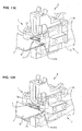
Une première étape de cette mise en place, montrée sur la
Dans une deuxième étape, on ressert les mâchoires 70 et 71 l'une sur l'autre (
Dans une troisième étape illustrée à la
La configuration ascendante de ces chemins de came fait que les flancs 11 et 12 s'écartent progressivement alors que, simultanément, les moyens de poussée évoqués plus haut rapprochent le curseur 1 du sachet S.The ascending configuration of these cam paths causes the
Ce mouvement de poussée est tel lorsque le curseur se trouve exactement en regard des profilés, les ergots 4 ont alors dépassé les chemins de came 50 et ne sont plus sollicités. Ils tendent alors à retrouver leur position initiale.This thrust movement is such that when the cursor is exactly opposite the profiles, the
C'est la situation de la
Dans une étape ultérieure, on procède à l'écartement des mâchoires 70 et 71 des pinces 7. C'est la situation de la
Enfin, on déplace la bande de sachets pour la mise en place d'un curseur sur un nouveau sachet (
On notera que l'orientation particulière (angle α) des faces extérieures des flancs 11 et 12 telle qu'illustrée à la
En résumé, le procédé selon l'invention comprend les étapes qui consistent à :
- ouvrir les mâchoires de chaque pince et y engager le bord du sachet pourvu de profilés complémentaires ;
- resserrer les mâchoires pour immobiliser le sachet ;
- pousser ledit curseur en direction du sachet, de manière à ce que ses ergots s'engagent sur les cames et assurent l'écartement de ses flancs, jusqu'à ce que les ergots dépassent lesdites cames et ne soient plus sollicités, ce qui provoque l'engagement du curseur sur les profilés.
- open the jaws of each clamp and engage the edge of the bag provided with complementary profiles;
- tighten the jaws to immobilize the bag;
- pushing said slider towards the bag, so that its lugs engage on the cams and ensure the spacing of its flanks, until the pins protrude from said cams and are no longer stressed, which causes the Cursor engagement on the profiles.
Claims (4)
- Device for placing a slider (1) for actuating closure profiles (P1, P2), notably for a closure assembly fitting out a bag (S), said slider comprising a base (10), two flanks (11, 12), and suitable means (13) for respectively urging said closure profiles (P1, P2) by bringing them closer together or by moving them apart depending on the direction of displacement of the slider along the profiles (P1, P2), in order to displace the profiles (P1, P2) between a closure engaging position and a separate opening position, as well as protruding urging spigots (4), in the direction of displacement on said flanks (11, 12) in the vicinity of the end of the latter, opposite to said base (10), in order to temporarily open it and facilitate its engagement on said profiles (P1 and P2) when urging is exerted on said spigots (4), on a bag (S) with mating closure profiles (P1, P2) or on an assembly of mating closure profiles (P1, P2) , characterized by the fact that it comprises at least one clamp (7) for retaining profiles (P1, P2) in a stable position, as well as means for pushing a slider (1) towards means (5) for temporarily moving said flanks (11, 12) away from the slider (1) in order to have it cooperate with said profiles (P1, P2), these means for moving them apart comprising cam paths (50) with an upward slope capable of cooperating with said spigots (4).
- Device according to claim 1, characterized by the fact that said cam paths (50) have a smaller longitudinal extent than the course of said slider (4), so that after having crossed the cam paths (50), the flanks (11, 12) of said slider (1) return to their initial position.
- Device according to any of claims 1 or 2, characterized by the fact that said cam paths (50) are borne by said clamp (7).
- A method for placing a slider (1) on a bag (S) with mating closure profiles (P1, P2), this slider (5) comprising a base (10), two flanks (11, 12) and suitable means (13) for respectively urging said closure profiles (P1, P2) by bringing them closer or moving them apart depending on the direction of displacement of the slider along the profiles (P1, P2), for displacing the profiles (P1, P2) between a closure engaging position and a separate opening position, as well as protruding urging spigots (4) on said flanks (11, 12) in the vicinity of the end of the latter, opposite to said base (10), in order to temporarily open it and facilitate its engagement onto said profiles (P1, P2) when urging is exerted on said spigots (4) by means of clamps (7), the faces of which opposite the jaws bear cams (5) with an upward slope, characterized by the fact that it comprises the steps of:- opening the jaws (70, 71) of each clamp (7) and engaging therein the edge of the bag (S) provided with mating profiles;- tightening the jaws (70, 71) for immobilizing the bag (S) ;- pushing said slider (1) towards the bag (S) so that its spigots (4) engage onto the cams (5) and ensure separation of its flanks (11; 12), until the spigots (4) jut out from said cams (5) and are no longer urged, which causes engagement of the slider (1) onto the profiles.
Applications Claiming Priority (2)
| Application Number | Priority Date | Filing Date | Title |
|---|---|---|---|
| FR0759545A FR2924312B1 (en) | 2007-12-04 | 2007-12-04 | CURSER WITH SOLLICITATION ERGOTS, SACHET EQUIPPED WITH SAME, CLOSURE ASSEMBLY AND DEVICE FOR SETTING IT UP. |
| PCT/EP2008/066474 WO2009071494A1 (en) | 2007-12-04 | 2008-11-28 | Slider with urging spigots |
Publications (2)
| Publication Number | Publication Date |
|---|---|
| EP2214972A1 EP2214972A1 (en) | 2010-08-11 |
| EP2214972B1 true EP2214972B1 (en) | 2014-03-19 |
Family
ID=39618993
Family Applications (1)
| Application Number | Title | Priority Date | Filing Date |
|---|---|---|---|
| EP08858129.3A Not-in-force EP2214972B1 (en) | 2007-12-04 | 2008-11-28 | Slider with camming spigots |
Country Status (4)
| Country | Link |
|---|---|
| US (1) | US20100310196A1 (en) |
| EP (1) | EP2214972B1 (en) |
| FR (1) | FR2924312B1 (en) |
| WO (1) | WO2009071494A1 (en) |
Families Citing this family (4)
| Publication number | Priority date | Publication date | Assignee | Title |
|---|---|---|---|---|
| FR2940751B1 (en) | 2009-01-05 | 2011-03-11 | S2F Flexico | CURRENT FOR ACTUATING RIGIDIFIER BAR PROFILES |
| FR2940752B1 (en) * | 2009-01-05 | 2011-03-04 | S2F Flexico | CURRENT FOR ACTUATING CLOSURE PROFILES WITH PRIVILEGED FOLDING LINES |
| FR2945188B1 (en) * | 2009-05-07 | 2011-09-30 | S2F Flexico | AUTOMATIC CURSOR INSTALLATION MACHINE AND ASSOCIATED METHOD. |
| US9216845B2 (en) * | 2012-10-26 | 2015-12-22 | Illinois Tool Works Inc. | Leak-resistant slider select zipper |
Family Cites Families (7)
| Publication number | Priority date | Publication date | Assignee | Title |
|---|---|---|---|---|
| US6584666B1 (en) * | 1999-06-10 | 2003-07-01 | The Glad Products Company | Method and apparatus for assembling slider members onto interlocking fastening strips using a rail |
| US7454823B2 (en) * | 1999-06-10 | 2008-11-25 | The Glad Products Company | Method and apparatus for assembling slider members onto interlocking fastening strips |
| US7097359B2 (en) * | 2003-02-20 | 2006-08-29 | Illinois Tool Works Inc. | Reclosable packaging having slider coupled to top of zipper |
| US7004631B1 (en) * | 2003-03-28 | 2006-02-28 | Showa Highpolymer Co., Ltd. | Portable laundry bag |
| FR2855153B1 (en) * | 2003-05-19 | 2007-04-13 | S2F Flexico | CLOSURE ASSEMBLY FOR A BAG COMPRISING MEANS AGAINST THE ARRACTION OF A CURSOR AND BAG EQUIPPED |
| US20060171610A1 (en) * | 2005-01-31 | 2006-08-03 | Buchman James E | Internal gripping slider and method |
| US20070065051A1 (en) * | 2005-09-21 | 2007-03-22 | Eads Claude A | Infestation resistant reclosable seal |
-
2007
- 2007-12-04 FR FR0759545A patent/FR2924312B1/en not_active Expired - Fee Related
-
2008
- 2008-11-28 US US12/745,529 patent/US20100310196A1/en not_active Abandoned
- 2008-11-28 WO PCT/EP2008/066474 patent/WO2009071494A1/en active Application Filing
- 2008-11-28 EP EP08858129.3A patent/EP2214972B1/en not_active Not-in-force
Also Published As
| Publication number | Publication date |
|---|---|
| US20100310196A1 (en) | 2010-12-09 |
| EP2214972A1 (en) | 2010-08-11 |
| FR2924312A1 (en) | 2009-06-05 |
| WO2009071494A1 (en) | 2009-06-11 |
| FR2924312B1 (en) | 2010-01-15 |
Similar Documents
| Publication | Publication Date | Title |
|---|---|---|
| EP1251285B1 (en) | Assembly for uniting two bodywork pieces at their edges and bodywork thus united | |
| EP1288405B1 (en) | Lock mechanism for a sliding window, door, or the like | |
| EP2214972B1 (en) | Slider with camming spigots | |
| FR2853367A1 (en) | FIXING DEVICE, PARTICULARLY FOR HOLDING A STACK OF AT LEAST TWO PANELS | |
| FR2873859A1 (en) | ELECTRICAL APPARATUS COMPRISING AN AUTOMATIC CONNECTION TERMINAL | |
| FR2682072A1 (en) | BONDING WELDING SHUTTER FOR A PRACTICAL OPENING IN A SHEET, PARTICULARLY FOR AUTOMOTIVE BODYWORK. | |
| FR3017252A1 (en) | CONNECTOR AND CORRESPONDING CONNECTOR ASSEMBLY | |
| FR2901419A1 (en) | Terminal block for use in electrical cabinet, has strip including step with socket to receive conductor`s end, and blade including section connecting handles, where portion of one handle holds strip`s stop from side opposite to other handle | |
| FR3008833A1 (en) | ELECTRICAL CONNECTOR SYSTEM | |
| EP2204331B1 (en) | Reinforced slider for a bag having closure profiles | |
| EP1976069A1 (en) | Power socket with mobile cover comprising locking/unlocking means with a latch | |
| EP0581638B1 (en) | Electrical connector | |
| WO2013007936A2 (en) | Pivoting splice plate for connecting segments of a wire-based cable tray | |
| FR2895939A1 (en) | CROCHET OF RECEPTION OF A JOINT TOURILLON | |
| FR2784807A1 (en) | Current socket mechanism having security shutter for internal contact elements, with shutter having centrally hinged counter direction guiding spring return flaps | |
| EP3115515B1 (en) | Pavement manhole with frame and panel | |
| FR2940752A1 (en) | CURRENT FOR ACTUATING CLOSURE PROFILES WITH PRIVILEGED FOLDING LINES | |
| EP2157592B1 (en) | Tilting articulated assembly | |
| EP2188809B1 (en) | Dvd case | |
| FR2712619A1 (en) | Housing for setting up concrete reinforcing elements | |
| EP2099000B1 (en) | Quick-fixing deposit device box | |
| EP2391503B1 (en) | Device and method for placing a slider on a bag with closure profiles | |
| EP1296006B1 (en) | Assistance tool for laying cladding tiles | |
| FR2809090A3 (en) | Storage container with hinged lid has the lid hinges clipped onto the lip of the container | |
| FR3097250A1 (en) | method of making an operating handle, operating handle and opening incorporating such an operating handle |
Legal Events
| Date | Code | Title | Description |
|---|---|---|---|
| PUAI | Public reference made under article 153(3) epc to a published international application that has entered the european phase |
Free format text: ORIGINAL CODE: 0009012 |
|
| 17P | Request for examination filed |
Effective date: 20100527 |
|
| AK | Designated contracting states |
Kind code of ref document: A1 Designated state(s): AT BE BG CH CY CZ DE DK EE ES FI FR GB GR HR HU IE IS IT LI LT LU LV MC MT NL NO PL PT RO SE SI SK TR |
|
| AX | Request for extension of the european patent |
Extension state: AL BA MK RS |
|
| RIN1 | Information on inventor provided before grant (corrected) |
Inventor name: ROGER, ANTONY |
|
| DAX | Request for extension of the european patent (deleted) | ||
| GRAP | Despatch of communication of intention to grant a patent |
Free format text: ORIGINAL CODE: EPIDOSNIGR1 |
|
| INTG | Intention to grant announced |
Effective date: 20130910 |
|
| GRAS | Grant fee paid |
Free format text: ORIGINAL CODE: EPIDOSNIGR3 |
|
| GRAA | (expected) grant |
Free format text: ORIGINAL CODE: 0009210 |
|
| AK | Designated contracting states |
Kind code of ref document: B1 Designated state(s): AT BE BG CH CY CZ DE DK EE ES FI FR GB GR HR HU IE IS IT LI LT LU LV MC MT NL NO PL PT RO SE SI SK TR |
|
| REG | Reference to a national code |
Ref country code: GB Ref legal event code: FG4D Free format text: NOT ENGLISH |
|
| REG | Reference to a national code |
Ref country code: CH Ref legal event code: EP |
|
| REG | Reference to a national code |
Ref country code: IE Ref legal event code: FG4D Free format text: LANGUAGE OF EP DOCUMENT: FRENCH |
|
| REG | Reference to a national code |
Ref country code: AT Ref legal event code: REF Ref document number: 657508 Country of ref document: AT Kind code of ref document: T Effective date: 20140415 |
|
| REG | Reference to a national code |
Ref country code: DE Ref legal event code: R096 Ref document number: 602008031016 Country of ref document: DE Effective date: 20140430 |
|
| PG25 | Lapsed in a contracting state [announced via postgrant information from national office to epo] |
Ref country code: NO Free format text: LAPSE BECAUSE OF FAILURE TO SUBMIT A TRANSLATION OF THE DESCRIPTION OR TO PAY THE FEE WITHIN THE PRESCRIBED TIME-LIMIT Effective date: 20140619 Ref country code: LT Free format text: LAPSE BECAUSE OF FAILURE TO SUBMIT A TRANSLATION OF THE DESCRIPTION OR TO PAY THE FEE WITHIN THE PRESCRIBED TIME-LIMIT Effective date: 20140319 |
|
| REG | Reference to a national code |
Ref country code: NL Ref legal event code: VDEP Effective date: 20140319 |
|
| REG | Reference to a national code |
Ref country code: AT Ref legal event code: MK05 Ref document number: 657508 Country of ref document: AT Kind code of ref document: T Effective date: 20140319 |
|
| REG | Reference to a national code |
Ref country code: LT Ref legal event code: MG4D |
|
| PG25 | Lapsed in a contracting state [announced via postgrant information from national office to epo] |
Ref country code: SE Free format text: LAPSE BECAUSE OF FAILURE TO SUBMIT A TRANSLATION OF THE DESCRIPTION OR TO PAY THE FEE WITHIN THE PRESCRIBED TIME-LIMIT Effective date: 20140319 Ref country code: CY Free format text: LAPSE BECAUSE OF FAILURE TO SUBMIT A TRANSLATION OF THE DESCRIPTION OR TO PAY THE FEE WITHIN THE PRESCRIBED TIME-LIMIT Effective date: 20140319 Ref country code: FI Free format text: LAPSE BECAUSE OF FAILURE TO SUBMIT A TRANSLATION OF THE DESCRIPTION OR TO PAY THE FEE WITHIN THE PRESCRIBED TIME-LIMIT Effective date: 20140319 |
|
| PG25 | Lapsed in a contracting state [announced via postgrant information from national office to epo] |
Ref country code: HR Free format text: LAPSE BECAUSE OF FAILURE TO SUBMIT A TRANSLATION OF THE DESCRIPTION OR TO PAY THE FEE WITHIN THE PRESCRIBED TIME-LIMIT Effective date: 20140319 Ref country code: LV Free format text: LAPSE BECAUSE OF FAILURE TO SUBMIT A TRANSLATION OF THE DESCRIPTION OR TO PAY THE FEE WITHIN THE PRESCRIBED TIME-LIMIT Effective date: 20140319 |
|
| PG25 | Lapsed in a contracting state [announced via postgrant information from national office to epo] |
Ref country code: IS Free format text: LAPSE BECAUSE OF FAILURE TO SUBMIT A TRANSLATION OF THE DESCRIPTION OR TO PAY THE FEE WITHIN THE PRESCRIBED TIME-LIMIT Effective date: 20140719 Ref country code: NL Free format text: LAPSE BECAUSE OF FAILURE TO SUBMIT A TRANSLATION OF THE DESCRIPTION OR TO PAY THE FEE WITHIN THE PRESCRIBED TIME-LIMIT Effective date: 20140319 Ref country code: BG Free format text: LAPSE BECAUSE OF FAILURE TO SUBMIT A TRANSLATION OF THE DESCRIPTION OR TO PAY THE FEE WITHIN THE PRESCRIBED TIME-LIMIT Effective date: 20140619 Ref country code: CZ Free format text: LAPSE BECAUSE OF FAILURE TO SUBMIT A TRANSLATION OF THE DESCRIPTION OR TO PAY THE FEE WITHIN THE PRESCRIBED TIME-LIMIT Effective date: 20140319 Ref country code: RO Free format text: LAPSE BECAUSE OF FAILURE TO SUBMIT A TRANSLATION OF THE DESCRIPTION OR TO PAY THE FEE WITHIN THE PRESCRIBED TIME-LIMIT Effective date: 20140319 Ref country code: EE Free format text: LAPSE BECAUSE OF FAILURE TO SUBMIT A TRANSLATION OF THE DESCRIPTION OR TO PAY THE FEE WITHIN THE PRESCRIBED TIME-LIMIT Effective date: 20140319 |
|
| PG25 | Lapsed in a contracting state [announced via postgrant information from national office to epo] |
Ref country code: PL Free format text: LAPSE BECAUSE OF FAILURE TO SUBMIT A TRANSLATION OF THE DESCRIPTION OR TO PAY THE FEE WITHIN THE PRESCRIBED TIME-LIMIT Effective date: 20140319 Ref country code: AT Free format text: LAPSE BECAUSE OF FAILURE TO SUBMIT A TRANSLATION OF THE DESCRIPTION OR TO PAY THE FEE WITHIN THE PRESCRIBED TIME-LIMIT Effective date: 20140319 Ref country code: SK Free format text: LAPSE BECAUSE OF FAILURE TO SUBMIT A TRANSLATION OF THE DESCRIPTION OR TO PAY THE FEE WITHIN THE PRESCRIBED TIME-LIMIT Effective date: 20140319 Ref country code: ES Free format text: LAPSE BECAUSE OF FAILURE TO SUBMIT A TRANSLATION OF THE DESCRIPTION OR TO PAY THE FEE WITHIN THE PRESCRIBED TIME-LIMIT Effective date: 20140319 |
|
| REG | Reference to a national code |
Ref country code: DE Ref legal event code: R097 Ref document number: 602008031016 Country of ref document: DE |
|
| PG25 | Lapsed in a contracting state [announced via postgrant information from national office to epo] |
Ref country code: PT Free format text: LAPSE BECAUSE OF FAILURE TO SUBMIT A TRANSLATION OF THE DESCRIPTION OR TO PAY THE FEE WITHIN THE PRESCRIBED TIME-LIMIT Effective date: 20140721 |
|
| PLBE | No opposition filed within time limit |
Free format text: ORIGINAL CODE: 0009261 |
|
| STAA | Information on the status of an ep patent application or granted ep patent |
Free format text: STATUS: NO OPPOSITION FILED WITHIN TIME LIMIT |
|
| PG25 | Lapsed in a contracting state [announced via postgrant information from national office to epo] |
Ref country code: DK Free format text: LAPSE BECAUSE OF FAILURE TO SUBMIT A TRANSLATION OF THE DESCRIPTION OR TO PAY THE FEE WITHIN THE PRESCRIBED TIME-LIMIT Effective date: 20140319 |
|
| 26N | No opposition filed |
Effective date: 20141222 |
|
| PG25 | Lapsed in a contracting state [announced via postgrant information from national office to epo] |
Ref country code: IT Free format text: LAPSE BECAUSE OF FAILURE TO SUBMIT A TRANSLATION OF THE DESCRIPTION OR TO PAY THE FEE WITHIN THE PRESCRIBED TIME-LIMIT Effective date: 20140319 |
|
| REG | Reference to a national code |
Ref country code: DE Ref legal event code: R097 Ref document number: 602008031016 Country of ref document: DE Effective date: 20141222 |
|
| PG25 | Lapsed in a contracting state [announced via postgrant information from national office to epo] |
Ref country code: BE Free format text: LAPSE BECAUSE OF NON-PAYMENT OF DUE FEES Effective date: 20141130 Ref country code: LU Free format text: LAPSE BECAUSE OF FAILURE TO SUBMIT A TRANSLATION OF THE DESCRIPTION OR TO PAY THE FEE WITHIN THE PRESCRIBED TIME-LIMIT Effective date: 20141128 Ref country code: MC Free format text: LAPSE BECAUSE OF FAILURE TO SUBMIT A TRANSLATION OF THE DESCRIPTION OR TO PAY THE FEE WITHIN THE PRESCRIBED TIME-LIMIT Effective date: 20140319 |
|
| REG | Reference to a national code |
Ref country code: CH Ref legal event code: PL |
|
| REG | Reference to a national code |
Ref country code: DE Ref legal event code: R082 Ref document number: 602008031016 Country of ref document: DE Representative=s name: HOEGER, STELLRECHT & PARTNER PATENTANWAELTE MB, DE |
|
| PG25 | Lapsed in a contracting state [announced via postgrant information from national office to epo] |
Ref country code: LI Free format text: LAPSE BECAUSE OF NON-PAYMENT OF DUE FEES Effective date: 20141130 Ref country code: SI Free format text: LAPSE BECAUSE OF FAILURE TO SUBMIT A TRANSLATION OF THE DESCRIPTION OR TO PAY THE FEE WITHIN THE PRESCRIBED TIME-LIMIT Effective date: 20140319 Ref country code: CH Free format text: LAPSE BECAUSE OF NON-PAYMENT OF DUE FEES Effective date: 20141130 |
|
| REG | Reference to a national code |
Ref country code: IE Ref legal event code: MM4A |
|
| PG25 | Lapsed in a contracting state [announced via postgrant information from national office to epo] |
Ref country code: IE Free format text: LAPSE BECAUSE OF NON-PAYMENT OF DUE FEES Effective date: 20141128 |
|
| REG | Reference to a national code |
Ref country code: FR Ref legal event code: PLFP Year of fee payment: 8 |
|
| PG25 | Lapsed in a contracting state [announced via postgrant information from national office to epo] |
Ref country code: GR Free format text: LAPSE BECAUSE OF FAILURE TO SUBMIT A TRANSLATION OF THE DESCRIPTION OR TO PAY THE FEE WITHIN THE PRESCRIBED TIME-LIMIT Effective date: 20140620 |
|
| PG25 | Lapsed in a contracting state [announced via postgrant information from national office to epo] |
Ref country code: HU Free format text: LAPSE BECAUSE OF FAILURE TO SUBMIT A TRANSLATION OF THE DESCRIPTION OR TO PAY THE FEE WITHIN THE PRESCRIBED TIME-LIMIT; INVALID AB INITIO Effective date: 20081128 Ref country code: TR Free format text: LAPSE BECAUSE OF FAILURE TO SUBMIT A TRANSLATION OF THE DESCRIPTION OR TO PAY THE FEE WITHIN THE PRESCRIBED TIME-LIMIT Effective date: 20140319 Ref country code: MT Free format text: LAPSE BECAUSE OF FAILURE TO SUBMIT A TRANSLATION OF THE DESCRIPTION OR TO PAY THE FEE WITHIN THE PRESCRIBED TIME-LIMIT Effective date: 20140319 |
|
| REG | Reference to a national code |
Ref country code: FR Ref legal event code: PLFP Year of fee payment: 9 |
|
| REG | Reference to a national code |
Ref country code: FR Ref legal event code: PLFP Year of fee payment: 10 |
|
| REG | Reference to a national code |
Ref country code: DE Ref legal event code: R082 Ref document number: 602008031016 Country of ref document: DE Representative=s name: HOEGER, STELLRECHT & PARTNER PATENTANWAELTE MB, DE |
|
| PGFP | Annual fee paid to national office [announced via postgrant information from national office to epo] |
Ref country code: GB Payment date: 20201118 Year of fee payment: 13 Ref country code: DE Payment date: 20201109 Year of fee payment: 13 Ref country code: FR Payment date: 20201110 Year of fee payment: 13 |
|
| REG | Reference to a national code |
Ref country code: DE Ref legal event code: R119 Ref document number: 602008031016 Country of ref document: DE |
|
| GBPC | Gb: european patent ceased through non-payment of renewal fee |
Effective date: 20211128 |
|
| PG25 | Lapsed in a contracting state [announced via postgrant information from national office to epo] |
Ref country code: GB Free format text: LAPSE BECAUSE OF NON-PAYMENT OF DUE FEES Effective date: 20211128 Ref country code: DE Free format text: LAPSE BECAUSE OF NON-PAYMENT OF DUE FEES Effective date: 20220601 |
|
| PG25 | Lapsed in a contracting state [announced via postgrant information from national office to epo] |
Ref country code: FR Free format text: LAPSE BECAUSE OF NON-PAYMENT OF DUE FEES Effective date: 20211130 |