EP2214925B1 - Dispositif d'entrainement a mecanisme hydraulique a boucle ouverte pouvant fonctionner comme pompe ou comme moteur - Google Patents
Dispositif d'entrainement a mecanisme hydraulique a boucle ouverte pouvant fonctionner comme pompe ou comme moteur Download PDFInfo
- Publication number
- EP2214925B1 EP2214925B1 EP08843643A EP08843643A EP2214925B1 EP 2214925 B1 EP2214925 B1 EP 2214925B1 EP 08843643 A EP08843643 A EP 08843643A EP 08843643 A EP08843643 A EP 08843643A EP 2214925 B1 EP2214925 B1 EP 2214925B1
- Authority
- EP
- European Patent Office
- Prior art keywords
- drive
- arrangement
- hydraulic mechanism
- hydraulic
- clutch
- Prior art date
- Legal status (The legal status is an assumption and is not a legal conclusion. Google has not performed a legal analysis and makes no representation as to the accuracy of the status listed.)
- Active
Links
Images


Classifications
-
- B—PERFORMING OPERATIONS; TRANSPORTING
- B60—VEHICLES IN GENERAL
- B60K—ARRANGEMENT OR MOUNTING OF PROPULSION UNITS OR OF TRANSMISSIONS IN VEHICLES; ARRANGEMENT OR MOUNTING OF PLURAL DIVERSE PRIME-MOVERS IN VEHICLES; AUXILIARY DRIVES FOR VEHICLES; INSTRUMENTATION OR DASHBOARDS FOR VEHICLES; ARRANGEMENTS IN CONNECTION WITH COOLING, AIR INTAKE, GAS EXHAUST OR FUEL SUPPLY OF PROPULSION UNITS IN VEHICLES
- B60K6/00—Arrangement or mounting of plural diverse prime-movers for mutual or common propulsion, e.g. hybrid propulsion systems comprising electric motors and internal combustion engines ; Control systems therefor, i.e. systems controlling two or more prime movers, or controlling one of these prime movers and any of the transmission, drive or drive units Informative references: mechanical gearings with secondary electric drive F16H3/72; arrangements for handling mechanical energy structurally associated with the dynamo-electric machine H02K7/00; machines comprising structurally interrelated motor and generator parts H02K51/00; dynamo-electric machines not otherwise provided for in H02K see H02K99/00
- B60K6/08—Prime-movers comprising combustion engines and mechanical or fluid energy storing means
- B60K6/12—Prime-movers comprising combustion engines and mechanical or fluid energy storing means by means of a chargeable fluidic accumulator
-
- B—PERFORMING OPERATIONS; TRANSPORTING
- B60—VEHICLES IN GENERAL
- B60K—ARRANGEMENT OR MOUNTING OF PROPULSION UNITS OR OF TRANSMISSIONS IN VEHICLES; ARRANGEMENT OR MOUNTING OF PLURAL DIVERSE PRIME-MOVERS IN VEHICLES; AUXILIARY DRIVES FOR VEHICLES; INSTRUMENTATION OR DASHBOARDS FOR VEHICLES; ARRANGEMENTS IN CONNECTION WITH COOLING, AIR INTAKE, GAS EXHAUST OR FUEL SUPPLY OF PROPULSION UNITS IN VEHICLES
- B60K6/00—Arrangement or mounting of plural diverse prime-movers for mutual or common propulsion, e.g. hybrid propulsion systems comprising electric motors and internal combustion engines ; Control systems therefor, i.e. systems controlling two or more prime movers, or controlling one of these prime movers and any of the transmission, drive or drive units Informative references: mechanical gearings with secondary electric drive F16H3/72; arrangements for handling mechanical energy structurally associated with the dynamo-electric machine H02K7/00; machines comprising structurally interrelated motor and generator parts H02K51/00; dynamo-electric machines not otherwise provided for in H02K see H02K99/00
- B60K6/20—Arrangement or mounting of plural diverse prime-movers for mutual or common propulsion, e.g. hybrid propulsion systems comprising electric motors and internal combustion engines ; Control systems therefor, i.e. systems controlling two or more prime movers, or controlling one of these prime movers and any of the transmission, drive or drive units Informative references: mechanical gearings with secondary electric drive F16H3/72; arrangements for handling mechanical energy structurally associated with the dynamo-electric machine H02K7/00; machines comprising structurally interrelated motor and generator parts H02K51/00; dynamo-electric machines not otherwise provided for in H02K see H02K99/00 the prime-movers consisting of electric motors and internal combustion engines, e.g. HEVs
- B60K6/42—Arrangement or mounting of plural diverse prime-movers for mutual or common propulsion, e.g. hybrid propulsion systems comprising electric motors and internal combustion engines ; Control systems therefor, i.e. systems controlling two or more prime movers, or controlling one of these prime movers and any of the transmission, drive or drive units Informative references: mechanical gearings with secondary electric drive F16H3/72; arrangements for handling mechanical energy structurally associated with the dynamo-electric machine H02K7/00; machines comprising structurally interrelated motor and generator parts H02K51/00; dynamo-electric machines not otherwise provided for in H02K see H02K99/00 the prime-movers consisting of electric motors and internal combustion engines, e.g. HEVs characterised by the architecture of the hybrid electric vehicle
-
- B—PERFORMING OPERATIONS; TRANSPORTING
- B60—VEHICLES IN GENERAL
- B60K—ARRANGEMENT OR MOUNTING OF PROPULSION UNITS OR OF TRANSMISSIONS IN VEHICLES; ARRANGEMENT OR MOUNTING OF PLURAL DIVERSE PRIME-MOVERS IN VEHICLES; AUXILIARY DRIVES FOR VEHICLES; INSTRUMENTATION OR DASHBOARDS FOR VEHICLES; ARRANGEMENTS IN CONNECTION WITH COOLING, AIR INTAKE, GAS EXHAUST OR FUEL SUPPLY OF PROPULSION UNITS IN VEHICLES
- B60K6/00—Arrangement or mounting of plural diverse prime-movers for mutual or common propulsion, e.g. hybrid propulsion systems comprising electric motors and internal combustion engines ; Control systems therefor, i.e. systems controlling two or more prime movers, or controlling one of these prime movers and any of the transmission, drive or drive units Informative references: mechanical gearings with secondary electric drive F16H3/72; arrangements for handling mechanical energy structurally associated with the dynamo-electric machine H02K7/00; machines comprising structurally interrelated motor and generator parts H02K51/00; dynamo-electric machines not otherwise provided for in H02K see H02K99/00
- B60K6/20—Arrangement or mounting of plural diverse prime-movers for mutual or common propulsion, e.g. hybrid propulsion systems comprising electric motors and internal combustion engines ; Control systems therefor, i.e. systems controlling two or more prime movers, or controlling one of these prime movers and any of the transmission, drive or drive units Informative references: mechanical gearings with secondary electric drive F16H3/72; arrangements for handling mechanical energy structurally associated with the dynamo-electric machine H02K7/00; machines comprising structurally interrelated motor and generator parts H02K51/00; dynamo-electric machines not otherwise provided for in H02K see H02K99/00 the prime-movers consisting of electric motors and internal combustion engines, e.g. HEVs
- B60K6/22—Arrangement or mounting of plural diverse prime-movers for mutual or common propulsion, e.g. hybrid propulsion systems comprising electric motors and internal combustion engines ; Control systems therefor, i.e. systems controlling two or more prime movers, or controlling one of these prime movers and any of the transmission, drive or drive units Informative references: mechanical gearings with secondary electric drive F16H3/72; arrangements for handling mechanical energy structurally associated with the dynamo-electric machine H02K7/00; machines comprising structurally interrelated motor and generator parts H02K51/00; dynamo-electric machines not otherwise provided for in H02K see H02K99/00 the prime-movers consisting of electric motors and internal combustion engines, e.g. HEVs characterised by apparatus, components or means specially adapted for HEVs
- B60K6/36—Arrangement or mounting of plural diverse prime-movers for mutual or common propulsion, e.g. hybrid propulsion systems comprising electric motors and internal combustion engines ; Control systems therefor, i.e. systems controlling two or more prime movers, or controlling one of these prime movers and any of the transmission, drive or drive units Informative references: mechanical gearings with secondary electric drive F16H3/72; arrangements for handling mechanical energy structurally associated with the dynamo-electric machine H02K7/00; machines comprising structurally interrelated motor and generator parts H02K51/00; dynamo-electric machines not otherwise provided for in H02K see H02K99/00 the prime-movers consisting of electric motors and internal combustion engines, e.g. HEVs characterised by apparatus, components or means specially adapted for HEVs characterised by the transmission gearings
- B60K6/365—Arrangement or mounting of plural diverse prime-movers for mutual or common propulsion, e.g. hybrid propulsion systems comprising electric motors and internal combustion engines ; Control systems therefor, i.e. systems controlling two or more prime movers, or controlling one of these prime movers and any of the transmission, drive or drive units Informative references: mechanical gearings with secondary electric drive F16H3/72; arrangements for handling mechanical energy structurally associated with the dynamo-electric machine H02K7/00; machines comprising structurally interrelated motor and generator parts H02K51/00; dynamo-electric machines not otherwise provided for in H02K see H02K99/00 the prime-movers consisting of electric motors and internal combustion engines, e.g. HEVs characterised by apparatus, components or means specially adapted for HEVs characterised by the transmission gearings with the gears having orbital motion
-
- B—PERFORMING OPERATIONS; TRANSPORTING
- B60—VEHICLES IN GENERAL
- B60K—ARRANGEMENT OR MOUNTING OF PROPULSION UNITS OR OF TRANSMISSIONS IN VEHICLES; ARRANGEMENT OR MOUNTING OF PLURAL DIVERSE PRIME-MOVERS IN VEHICLES; AUXILIARY DRIVES FOR VEHICLES; INSTRUMENTATION OR DASHBOARDS FOR VEHICLES; ARRANGEMENTS IN CONNECTION WITH COOLING, AIR INTAKE, GAS EXHAUST OR FUEL SUPPLY OF PROPULSION UNITS IN VEHICLES
- B60K6/00—Arrangement or mounting of plural diverse prime-movers for mutual or common propulsion, e.g. hybrid propulsion systems comprising electric motors and internal combustion engines ; Control systems therefor, i.e. systems controlling two or more prime movers, or controlling one of these prime movers and any of the transmission, drive or drive units Informative references: mechanical gearings with secondary electric drive F16H3/72; arrangements for handling mechanical energy structurally associated with the dynamo-electric machine H02K7/00; machines comprising structurally interrelated motor and generator parts H02K51/00; dynamo-electric machines not otherwise provided for in H02K see H02K99/00
- B60K6/20—Arrangement or mounting of plural diverse prime-movers for mutual or common propulsion, e.g. hybrid propulsion systems comprising electric motors and internal combustion engines ; Control systems therefor, i.e. systems controlling two or more prime movers, or controlling one of these prime movers and any of the transmission, drive or drive units Informative references: mechanical gearings with secondary electric drive F16H3/72; arrangements for handling mechanical energy structurally associated with the dynamo-electric machine H02K7/00; machines comprising structurally interrelated motor and generator parts H02K51/00; dynamo-electric machines not otherwise provided for in H02K see H02K99/00 the prime-movers consisting of electric motors and internal combustion engines, e.g. HEVs
- B60K6/42—Arrangement or mounting of plural diverse prime-movers for mutual or common propulsion, e.g. hybrid propulsion systems comprising electric motors and internal combustion engines ; Control systems therefor, i.e. systems controlling two or more prime movers, or controlling one of these prime movers and any of the transmission, drive or drive units Informative references: mechanical gearings with secondary electric drive F16H3/72; arrangements for handling mechanical energy structurally associated with the dynamo-electric machine H02K7/00; machines comprising structurally interrelated motor and generator parts H02K51/00; dynamo-electric machines not otherwise provided for in H02K see H02K99/00 the prime-movers consisting of electric motors and internal combustion engines, e.g. HEVs characterised by the architecture of the hybrid electric vehicle
- B60K6/44—Series-parallel type
-
- B—PERFORMING OPERATIONS; TRANSPORTING
- B60—VEHICLES IN GENERAL
- B60K—ARRANGEMENT OR MOUNTING OF PROPULSION UNITS OR OF TRANSMISSIONS IN VEHICLES; ARRANGEMENT OR MOUNTING OF PLURAL DIVERSE PRIME-MOVERS IN VEHICLES; AUXILIARY DRIVES FOR VEHICLES; INSTRUMENTATION OR DASHBOARDS FOR VEHICLES; ARRANGEMENTS IN CONNECTION WITH COOLING, AIR INTAKE, GAS EXHAUST OR FUEL SUPPLY OF PROPULSION UNITS IN VEHICLES
- B60K6/00—Arrangement or mounting of plural diverse prime-movers for mutual or common propulsion, e.g. hybrid propulsion systems comprising electric motors and internal combustion engines ; Control systems therefor, i.e. systems controlling two or more prime movers, or controlling one of these prime movers and any of the transmission, drive or drive units Informative references: mechanical gearings with secondary electric drive F16H3/72; arrangements for handling mechanical energy structurally associated with the dynamo-electric machine H02K7/00; machines comprising structurally interrelated motor and generator parts H02K51/00; dynamo-electric machines not otherwise provided for in H02K see H02K99/00
- B60K6/20—Arrangement or mounting of plural diverse prime-movers for mutual or common propulsion, e.g. hybrid propulsion systems comprising electric motors and internal combustion engines ; Control systems therefor, i.e. systems controlling two or more prime movers, or controlling one of these prime movers and any of the transmission, drive or drive units Informative references: mechanical gearings with secondary electric drive F16H3/72; arrangements for handling mechanical energy structurally associated with the dynamo-electric machine H02K7/00; machines comprising structurally interrelated motor and generator parts H02K51/00; dynamo-electric machines not otherwise provided for in H02K see H02K99/00 the prime-movers consisting of electric motors and internal combustion engines, e.g. HEVs
- B60K6/42—Arrangement or mounting of plural diverse prime-movers for mutual or common propulsion, e.g. hybrid propulsion systems comprising electric motors and internal combustion engines ; Control systems therefor, i.e. systems controlling two or more prime movers, or controlling one of these prime movers and any of the transmission, drive or drive units Informative references: mechanical gearings with secondary electric drive F16H3/72; arrangements for handling mechanical energy structurally associated with the dynamo-electric machine H02K7/00; machines comprising structurally interrelated motor and generator parts H02K51/00; dynamo-electric machines not otherwise provided for in H02K see H02K99/00 the prime-movers consisting of electric motors and internal combustion engines, e.g. HEVs characterised by the architecture of the hybrid electric vehicle
- B60K6/48—Parallel type
-
- F—MECHANICAL ENGINEERING; LIGHTING; HEATING; WEAPONS; BLASTING
- F16—ENGINEERING ELEMENTS AND UNITS; GENERAL MEASURES FOR PRODUCING AND MAINTAINING EFFECTIVE FUNCTIONING OF MACHINES OR INSTALLATIONS; THERMAL INSULATION IN GENERAL
- F16H—GEARING
- F16H61/00—Control functions within control units of change-speed- or reversing-gearings for conveying rotary motion ; Control of exclusively fluid gearing, friction gearing, gearings with endless flexible members or other particular types of gearing
- F16H61/38—Control of exclusively fluid gearing
- F16H61/40—Control of exclusively fluid gearing hydrostatic
- F16H61/42—Control of exclusively fluid gearing hydrostatic involving adjustment of a pump or motor with adjustable output or capacity
- F16H61/438—Control of forward-reverse switching, e.g. control of the swash plate causing discharge in two directions
-
- B—PERFORMING OPERATIONS; TRANSPORTING
- B60—VEHICLES IN GENERAL
- B60K—ARRANGEMENT OR MOUNTING OF PROPULSION UNITS OR OF TRANSMISSIONS IN VEHICLES; ARRANGEMENT OR MOUNTING OF PLURAL DIVERSE PRIME-MOVERS IN VEHICLES; AUXILIARY DRIVES FOR VEHICLES; INSTRUMENTATION OR DASHBOARDS FOR VEHICLES; ARRANGEMENTS IN CONNECTION WITH COOLING, AIR INTAKE, GAS EXHAUST OR FUEL SUPPLY OF PROPULSION UNITS IN VEHICLES
- B60K6/00—Arrangement or mounting of plural diverse prime-movers for mutual or common propulsion, e.g. hybrid propulsion systems comprising electric motors and internal combustion engines ; Control systems therefor, i.e. systems controlling two or more prime movers, or controlling one of these prime movers and any of the transmission, drive or drive units Informative references: mechanical gearings with secondary electric drive F16H3/72; arrangements for handling mechanical energy structurally associated with the dynamo-electric machine H02K7/00; machines comprising structurally interrelated motor and generator parts H02K51/00; dynamo-electric machines not otherwise provided for in H02K see H02K99/00
- B60K6/08—Prime-movers comprising combustion engines and mechanical or fluid energy storing means
- B60K6/12—Prime-movers comprising combustion engines and mechanical or fluid energy storing means by means of a chargeable fluidic accumulator
- B60K2006/126—Prime-movers comprising combustion engines and mechanical or fluid energy storing means by means of a chargeable fluidic accumulator the hydraulic accumulator starts the engine
-
- B—PERFORMING OPERATIONS; TRANSPORTING
- B60—VEHICLES IN GENERAL
- B60W—CONJOINT CONTROL OF VEHICLE SUB-UNITS OF DIFFERENT TYPE OR DIFFERENT FUNCTION; CONTROL SYSTEMS SPECIALLY ADAPTED FOR HYBRID VEHICLES; ROAD VEHICLE DRIVE CONTROL SYSTEMS FOR PURPOSES NOT RELATED TO THE CONTROL OF A PARTICULAR SUB-UNIT
- B60W50/00—Details of control systems for road vehicle drive control not related to the control of a particular sub-unit, e.g. process diagnostic or vehicle driver interfaces
- B60W2050/0001—Details of the control system
- B60W2050/0002—Automatic control, details of type of controller or control system architecture
- B60W2050/0012—Feedforward or open loop systems
-
- F—MECHANICAL ENGINEERING; LIGHTING; HEATING; WEAPONS; BLASTING
- F16—ENGINEERING ELEMENTS AND UNITS; GENERAL MEASURES FOR PRODUCING AND MAINTAINING EFFECTIVE FUNCTIONING OF MACHINES OR INSTALLATIONS; THERMAL INSULATION IN GENERAL
- F16H—GEARING
- F16H37/00—Combinations of mechanical gearings, not provided for in groups F16H1/00 - F16H35/00
- F16H37/02—Combinations of mechanical gearings, not provided for in groups F16H1/00 - F16H35/00 comprising essentially only toothed or friction gearings
- F16H37/06—Combinations of mechanical gearings, not provided for in groups F16H1/00 - F16H35/00 comprising essentially only toothed or friction gearings with a plurality of driving or driven shafts; with arrangements for dividing torque between two or more intermediate shafts
- F16H37/08—Combinations of mechanical gearings, not provided for in groups F16H1/00 - F16H35/00 comprising essentially only toothed or friction gearings with a plurality of driving or driven shafts; with arrangements for dividing torque between two or more intermediate shafts with differential gearing
- F16H37/0833—Combinations of mechanical gearings, not provided for in groups F16H1/00 - F16H35/00 comprising essentially only toothed or friction gearings with a plurality of driving or driven shafts; with arrangements for dividing torque between two or more intermediate shafts with differential gearing with arrangements for dividing torque between two or more intermediate shafts, i.e. with two or more internal power paths
- F16H37/084—Combinations of mechanical gearings, not provided for in groups F16H1/00 - F16H35/00 comprising essentially only toothed or friction gearings with a plurality of driving or driven shafts; with arrangements for dividing torque between two or more intermediate shafts with differential gearing with arrangements for dividing torque between two or more intermediate shafts, i.e. with two or more internal power paths at least one power path being a continuously variable transmission, i.e. CVT
- F16H2037/088—Power split variators with summing differentials, with the input of the CVT connected or connectable to the input shaft
-
- F—MECHANICAL ENGINEERING; LIGHTING; HEATING; WEAPONS; BLASTING
- F16—ENGINEERING ELEMENTS AND UNITS; GENERAL MEASURES FOR PRODUCING AND MAINTAINING EFFECTIVE FUNCTIONING OF MACHINES OR INSTALLATIONS; THERMAL INSULATION IN GENERAL
- F16H—GEARING
- F16H47/00—Combinations of mechanical gearing with fluid clutches or fluid gearing
- F16H47/02—Combinations of mechanical gearing with fluid clutches or fluid gearing the fluid gearing being of the volumetric type
- F16H47/04—Combinations of mechanical gearing with fluid clutches or fluid gearing the fluid gearing being of the volumetric type the mechanical gearing being of the type with members having orbital motion
-
- Y—GENERAL TAGGING OF NEW TECHNOLOGICAL DEVELOPMENTS; GENERAL TAGGING OF CROSS-SECTIONAL TECHNOLOGIES SPANNING OVER SEVERAL SECTIONS OF THE IPC; TECHNICAL SUBJECTS COVERED BY FORMER USPC CROSS-REFERENCE ART COLLECTIONS [XRACs] AND DIGESTS
- Y02—TECHNOLOGIES OR APPLICATIONS FOR MITIGATION OR ADAPTATION AGAINST CLIMATE CHANGE
- Y02T—CLIMATE CHANGE MITIGATION TECHNOLOGIES RELATED TO TRANSPORTATION
- Y02T10/00—Road transport of goods or passengers
- Y02T10/60—Other road transportation technologies with climate change mitigation effect
- Y02T10/62—Hybrid vehicles
Definitions
- This invention relates to a drive arrangement. More specifically, but not exclusively, this invention relates to a drive arrangement utilizing hybrid power for vehicles and having regenerative braking and engine optimization capabilities.
- Some well-known concepts are that of regenerative braking and engine optimization.
- Vehicles having regenerative braking are equipped with an energy storage device for capturing and storing energy that would normally be released as heat from normal braking and dissipate into the atmosphere.
- Engine optimization is the concept to use the engine only in certain predetermined modes where the engine operates more efficiently and either to store any excess energy produced by the engine by some means, such as batteries or hydraulic pressure and then to use the stored energy during periods where the engine is not in use.
- One well-known regenerative braking system is to use an electrical motor generator system to brake a vehicle, either instead of or together with conventional brakes. The generator creates electricity and charges up a battery while it is used to slow the vehicle down. The charged battery is then used to drive electric motor(s) to power the drive train of the vehicle again.
- the same concept can be used for engine optimization where the electric generator is used to store engine energy and then this energy is used during periods when the engine is not used.
- WO 2007/104539A discloses drive arrangement suitable for driving a final drive, the arrangement comprising:
- the invention is a drive arrangement as defined in claim 1, which
- the hydraulic mechanism may have a hydraulic energy storage means associated with it, such as an accumulator tank.
- the hydraulic mechanism may comprise an open loop over-centre variable displacement hydraulic device that can be operated as a pump or as a motor.
- a hydraulic device that is operable as a pump or a motor, is sometimes hereinafter referred to as a pump/motor device.
- the hydraulic device may be an open loop over-centre variable displacement axial piston hydraulic device that can be operated as a pump or as a motor.
- the hydraulic device may be an open loop axial piston hydraulic device having a manipulatable swash-plate that may be controlled to move over-centre to allow the hydraulic device to operate as a pump or as a motor.
- the hydraulic device may be a gear pump/motor device.
- the hydraulic mechanism may comprise at least first and second devices, each selectively operable as a pump or a motor.
- the at least first and second pump/motor devices may be connected in series and configured to operate independently of each other.
- the pump/motor devices may be operable independently of each other, so that at least one of the pump/motor devices may operate as a pump, while at least one other pump/motor device operates as a motor.
- the power ratio of the two pump/motor devices may be in the order of 1:3.
- At least one of the pump/motor devices may be a gear pump/motor device and another a variable displacement device.
- the power ratio of the two pump/motor devices may be in the order of 2:2.
- the power-splitting gear arrangement may be mechanical.
- the power-splitting gear arrangement may comprise a planetary gear or any differential-type mechanical connection that allows a split in the amount and direction of power transmitted through it.
- the power splitting gear arrangement may be connected to any of the first drive means, the first hydraulic device, and the final drive by a respective shaft.
- the power splitting gear arrangement may be connected to any of the first drive means, the hydraulic device, and the final drive by a drive belt.
- the power-splitting gear arrangement may include a clutch and brake arrangement whereby the gear ratios between the first drive means, the first hydraulic device, and the final drive may be varied by coupling and/or engaging the clutch or brake or both.
- the clutch and brake arrangement may serve to disconnect any of the first drive means, the first hydraulic device, and the final drive from the gear arrangement, while locking any of the gears in a stationary position.
- the gears may be locked by locking the shafts that they are attached to.
- the first drive means may be an internal combustion engine, such as a diesel or petrol engine.
- the first drive means may be an external combustion engine, such as a Stirling engine.
- the first drive means may be an electrical motor, and may be accompanied by an electrical storage means such as electrical batteries.
- the arrangement may further include a control system for controlling the relative outputs and inputs of any combination of the hydraulic device, first drive means, or gear arrangement and the various clutches and brakes in the system.
- the control system may further control operation of the clutch and brake arrangement.
- the control system may operate according to a control algorithm.
- the drive arrangement may be used in a vehicle.
- the control system may control the relative outputs and inputs of any combination of the first hydraulic device, first drive means, clutch and brake arrangement or gearbox according to a terrain logging and prediction facility.
- the terrain logging and prediction facility may be incorporated in the control algorithm.
- the terrain logging and prediction facility may operate by means of a
- GPS Global Positioning System
- electronic mapping system an electronic mapping system
- the arrangement may include a second hydraulic mechanism configured to allow the first drive arrangement to store energy in the hydraulic energy storage means while the energy is being utilised by the first hydraulic mechanism to drive the final drive.
- the second hydraulic mechanism may be similar to the first hydraulic mechanism.
- the second hydraulic mechanism may also be configured to drive the final drive.
- variable displacement axial piston hydraulic device comprising:
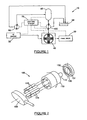
- an embodiment of a drive arrangement according to the invention is generally indicated by reference numeral 10.
- a drive arrangement 10 for driving a final drive 20 comprises a first drive means such as an internal combustion (IC) engine 30; and a power-splitting gear arrangement, such as a planetary gearbox 40 utilizing known technology.
- the drive arrangement 10 further comprises a hydraulic mechanism 100 operable as either a pump or a motor. Further, the hydraulic mechanism 100 is capable of being driven from the IC engine 30 or from the final drive 20 or both concurrently, acting through the gearbox 40; and the final drive 20 is capable of being driven through the gearbox 40 by the IC engine 30 or the hydraulic mechanism 100 or both concurrently.
- the hydraulic mechanism 100 has a hydraulic energy storage means, such as an accumulator tank 60, associated with it, as well as a reservoir tank 56.
- a hydraulic energy storage means such as an accumulator tank 60, associated with it, as well as a reservoir tank 56.
- the hydraulic mechanism 100 comprises an open loop over-centre variable displacement hydraulic device that can be operated as a pump or as a motor, such as an axial piston-type hydraulic device utilizing a variable swash-plate 105, Figure 2 , or a bent-axis type axial piston pump (not shown) wherein the angle of the swash-plate 105 or equivalent may be varied to move over-centre.
- an open loop over-centre variable displacement hydraulic device that can be operated as a pump or as a motor, such as an axial piston-type hydraulic device utilizing a variable swash-plate 105, Figure 2 , or a bent-axis type axial piston pump (not shown) wherein the angle of the swash-plate 105 or equivalent may be varied to move over-centre.
- the hydraulic device 100 shown in figure 3 and 4 comprises a rotating cylinder barrel 110, which is fixed to a shaft 111 so that it is able to be rotated by the shaft 111, or to rotate the shaft 111, the cylinder barrel 110 further having a plurality of pistons 115 which are able to reciprocate within cylinder bores 120 (as shown in figure 3 ) within the cylinder barrel 110,
- the cylinder bores have a terminal end 121 within the cylinder barrel 110, and an open end 122 at the swash-plate 105 side of the cylinder barrel 110.
- the hydraulic device 100 further comprises a swash-plate 105, movable through a range of angles relative to the cylinder barrel 110. The angle at which the facing side 106 of the swash-plate 105 is exactly perpendicular to the axis of the cylinder barrel 110 is regarded as the zero angle.
- the swash-plate 105 is able to move through a range of both positive and negative angles.
- the hydraulic device 100 further comprises a porting plate 130 which is stationary and which sealingly abuts against the cylinder barrel 110 as the cylinder barrel 110 rotates.
- the porting plate 130 has a high pressure channel 131 and a low pressure channel 132 in it, which are in fluid communication with the cylinder bores 120 in the cylinder barrel 110 through porting passages 140 leading from the terminal end of the cylinder bores 120 in the terminal end 121 of the cylinder bores 120.
- the cylinder bores 120 will be in alternating fluid communication with the high pressure channel 131 and the low pressure channel 132.
- a high pressure fluid is supplied to the porting plate 130 at the high pressure channel 131, while the low pressure channel 132 is left at a relatively low pressure (such as ambient pressure or slightly higher than this).
- the pistons 115 are held against the swash-plate 105 by the pressure within the cylinder bores 120 or by biasing means (not shown).
- Lubricated slippers 125 are mounted onto the ends of the pistons 115 closest to the swash-plate 105 by means of a ball coupling 126.
- the cylinder bore 120 of a piston 115 will come into fluid communication with the high pressure port 131 of the porting plate 130 at a point where the swash-plate 105 has pushed the piston 115 into the cylinder bore 120 to its most retracted extent.
- High pressure, from the high-pressure channel 131, acting on a piston is transferred as a force to the swash-plate 105 through the slipper 125, which also transmits the reactive force of the swash-plate 105 on the slipper 125 back to the piston 115.
- the reactive force of the swash-plate 105 on the slippers 125 has a transverse component, which is also transferred to the piston 115, which causes the cylinder barrel 110 and hence the shaft 111 to move.
- the piston 115 will reach its most extended point, at which time the cylinder bore 120 of the piston 115 will change to being in fluid communication with the low pressure channel 132 of the porting plate 130.
- the force of the swash-plate 105 against the piston 115 will push the piston 115 into the cylinder bore 120 with little resistance, as there will be little or no pressure in the cylinder bore acting against the piston 115.
- the low-pressure fluid will be expelled from the cylinder bore 120 to a fluid reservoir 56 (shown in Figure 1 ).
- the hydraulic device 100 When the hydraulic device 100 is used as a pump, a torque is applied to the shaft 111, causing the cylinder barrel 110 to rotate about its axis.
- the hydraulic device 100 remains the same, except that the swash-plate 105 is moved to an over centre position (i.e. past the zero angle) from the position it was in when the device 100 was used as a motor. Now, the pistons 115 will be pushed to a retracted position against the fluid pressure in the high-pressure channel 131, thereby increasing the pressure in the high-pressure channel 131. This pressure is dispersed to an accumulator tank 60.
- the piston When the cylinder bore 120 is in fluid communication with the low pressure channel 132, the piston is moved into an extended position by a slight pressure in the cylinder bore 120, or by a biasing means (not shown).
- the load created by the hydraulic pump/motor device when used as a pump may be finely controlled from zero load (when the facing side 106 of the swash-plate 105 is disposed perpendicularly to the axis of rotation of the cylinder barrel 110) to maximum load through an infinite number of steps.
- the amount of power delivered by the hydraulic pump/motor device when used as a motor may be increased from zero power to maximum available power through an infinite number of steps.
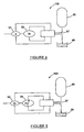
- the hydraulic mechanism 100 may comprise a pair of pump/motor devices.
- the pump/motor devices may be gear pump/motor arrangements 51 and 52 (as shown in figure 4 ) connected in series, the pump/motor devices 51 and 52 being associated with a reservoir tank 56 and an accumulator tank 60.
- the pair of gear pump/motor devices 51 and 52 are connected in series, and each can be operated independently of each other through a valve control manifold 57 to act as either a pump or motor.
- a preferable power ratio between the two gear pump/motor devices 51 and 52 wilt be in the order of 1 :3.
- the hydraulic mechanism 100 can provide stepped increments in relative power as both a motor and as a pump from -4 (1 - 3), -3 (0-3), -2 (+ 1-3), -1 (-1-0), O, 1 (+ 1 -0), 2(-1 +3), 3 (0 + 3), and 4 (+ 1 + 3).
- At least one of the pump/motor devices 53 and 54 may be a variable displacement pump/motor device 54.
- These pump/motor devices 53 & 54 are also associated with a reservoir tank 56 and an accumulator tank 60, and controlled through a valve control manifold 57.
- the preferred ratio between the pair of pump/motor devices 53 and 54 will be approximately 2:2.
- the hydraulic mechanism 100 can provide an infinitely variable control of the relative power provided by the hydraulic mechanism when used as motor, as well as an infinitely variable control of the relative load created by the hydraulic mechanism when used as a pump, ranging from -4 to + 4,
- the variable displacement pump/motor device 54 may have a slightly increased size, to accommodate leakage losses.
- the power splitting gear arrangement is a planetary gearbox 40, although it can also be any differential-type mechanical connection that allows a split in the amount and direction of power transmitted through it.
- a power splitting planetary gearbox 40 according to the invention is shown in Figure 6 .
- Any of either of the 1C engine 30, the hydraulic device 100, or the final drive 20 can be connected to any of a ring gear 41, sun gear 42 or a planet carrier gear 43 by a series of clutches (not shown) by known means found on automatic gearboxes.
- the hydraulic mechanism 100 is coupled to the ring gear 41 by means of an idler gear 44.
- the gearbox 40 also includes a first clutch and brake arrangement 45 along the shaft to the IC engine 30, whereby the engine may be disconnected from the gearbox 40 by a clutch part of the first clutch and brake arrangement 45, and a disconnected shaft on the gearbox side may be locked by the brake part of the first clutch and brake arrangement 45, so as not to move.
- the gearbox includes a second clutch and brake arrangement 46 along a shaft to hydraulic mechanism 100, whereby the hydraulic mechanism 100 may be disconnected from the gearbox by a clutch part of the second clutch and brake arrangement 46.
- the gearbox 40 can be prevented from overspeeding by a first brake part (not shown) of the second clutch and brake arrangement 46 which is located on the hydraulic mechanism side of the disconnected shaft and which can be locked.
- a second brake part (not shown) of the second clutch and brake arrangement 46, located on the gearbox 40 side of the disconnected shaft, may be locked so as to prevent the disconnected shaft from rotating freely.
- the gearbox includes a third clutch and brake arrangement 47 along the shaft to the final drive 20, whereby the final drive 20 may be disconnected from the gearbox 40 by a clutch part of the third clutch and brake arrangement 47, and a brake part (not shown) located on the gearbox 40 side of the disconnected shaft may be locked so to prevent the disconnected shaft from rotating freely.
- the gearbox 40 may have an internal set of clutches (not shown) which allows any two of the sun, planet carrier and ring gears to be locked together, so that the planetary gears 41, 42 and 43 of the gearbox 40 operate as a normal gear set, and not as a differential or power splitting unit.
- the operation of the drive arrangement 10 will include six main modes of operation.
- the gearbox 40 will operate as a speed-summing differential, being driven mainly by the IC engine 30 and where the hydraulic mechanism 100 is controlled to balance the torque of the IC engine 30 and vary the output speed and in turn driving the final drive 20.
- the hydraulic mechanism 100 can either operate as a pump or as a motor depending on the torque and speed settings of the IC engine 30, the final drive shaft 20 torque and speed and similarly the torque and speed setting of the hydraulic mechanism 100.
- the IC engine 30 is connected to the gearbox 40 at the second clutch and brake arrangement 46 and unlocked, the hydraulic mechanism 100 is connected to the gearbox 40 and the brake part is unlocked, and the final drive is connected to the gearbox 40 and unlocked.
- the differential will sum the speed of the drive input shafts from the IC engine 30 and the hydraulic mechanism 100, but torque to the final drive 20 is controlled (and balanced between the IC engine 30, the hydraulic mechanism 100 and the final drive 20), by firstly varying the performance of the IC engine 30 (both the torque setting and speed setting) and secondly varying the swash-plate 105 angle of the hydraulic mechanism 100 to give the desired output speed and torque on shaft 20.
- the internal set of clutches (not shown) in the gearbox which allows any two of the sun gear 42, ring gear 41 and planetary carrier gears 43 to be locked together will be locked.
- the IC engine 30 is connected and unlocked, the hydraulic mechanism 100 is connected and unlocked and the final drive 20 is connected and unlocked. There will be a direct relationship between all the speeds of the IC engine 30, the hydraulic mechanism 100 and the final drive 20, which will depend on the mechanical gear ratios of the gearbox 40.
- the hydraulic mechanism 100 may be used as a pump or as a motor to drain or supplement torque supplied to the final drive 20 by the IC engine 30. If used as a drain, the energy drained will be stored in the accumulator tank 60 as pressure.
- the speed will be fixed by the IC engine 30 and the load speed, while the torque will be a summation of the torque of the IC engine 30 plus the torque of the hydraulic mechanism 100 (adding it when it act as a motor or minusing it when it acts as a pump).
- This mode would normally be used at higher final drive speeds, although it may also be used as a launch assist for improved acceleration from low speeds.
- the hydraulic mechanism 100 is the only source of power to drive the final drive 20.
- the hydraulic mechanism 100 and the final drive 20 are connected to the gearbox 40 and unlocked, while the IC engine 30 is disconnected and the shaft to the engine is locked.
- the IC engine 30 may be idling or off, since it is disconnected.
- This mode would normally be used for optimal fuel consumption when pulling off from rest or at other times when the IC engine 30 would not be operating at optimum efficiency. Alternatively, this mode could be used at times when there is sufficient stored energy to propel the vehicle for a period, without the IC engine.
- the final drive 20 When operating in the fifth mode, the final drive 20 is locked, although it may be connected (if the final drive is at rest) or disconnected (if the final drive 20 is not at rest but does not require drive power from the IC engine 30 or the hydraulic mechanism 100).
- the IC engine 30 is connected and unlocked and the hydraulic mechanism is connected and unlocked. In this mode, the IC engine 30 may be used to charge up the hydraulic mechanism 100 while the final drive 20 is at rest or freewheeling.
- the final drive 20 is being braked and it will be supplying drive power to the gearbox 40 (i.e. regenerative braking).
- the final drive 20 and the hydraulic mechanism 100 are connected and unlocked, and the IC engine 30 is disconnected and locked.
- the IC engine may be idling or off, since it is disconnected.
- the drive arrangement 10 further comprises a control system 70 for controlling the relative outputs and inputs of any combination of the hydraulic mechanism 100, IC engine 30, final drive 20, gearbox 40 or the various clutch and brake arrangements 45, 46 & 47, the internal clutch arrangement or the known clutch arrangements used to change the gear ratios between input and output shafts.
- IC engines 30 have increased levels of efficiency at various speeds, which efficiency is also dependent on the level of throttle input to the IC engine 30.
- control system 70 will allow the arrangement 10 to be controlled to allow for the optimisation of various parameters such as maximum power, efficiency of power usage, fuel efficiency, and the like.
- various parameters such as maximum power, efficiency of power usage, fuel efficiency, and the like.
- the hydraulic device 100 may be used as a pump, thereby acting as a load on the power being transmitted from the final drive during braking, in order to store at least a portion of the energy usually lost as heat during braking as pressure in the accumulator tank 60.
- This stored pressure in the accumulator tank 60 can be utilised later on to supplement or even completely replace the power transmitted from the IC engine 30 to drive the final drive 20, which in this case would be the drive wheels of the vehicle.
- the drive arrangement may have a second hydraulic pump 80 (shown in figure 1 ) connected between the gearbox 40 and the accumulator tank 60.
- This pump 80 will allow the IC engine 30 to charge the accumulator tank 60 and drive the final drive 20 while the energy stored in the accumulator tank 60 is being used to drive the hydraulic mechanism 100 as a motor, thereby supplementing the drive from the IC engine 30.
- the efficiencies of the various drive means may be optimized for various loads and performance requirements.
- the hydraulic mechanism may be used as a pump to increase the loading on the iC engine 30, while changing aspects of the IC engine 30, such as engine speed, throttle levels and torque loading so that the IC engine 30 will be operating at an increased overall efficiency.
- the extra energy produced by the IC motor 30 at better efficiencies is not lost, but stored for later use when there is demand for it.
- the control system 70 similarly would be able to control the clutch and brake arrangement controlling the gear ratios in operation between the IC engine 30, final drive 20, and the hydraulic mechanism 100 in order to optimize a particular aspect such as fuel economy, acceleration (where the arrangement 10 is utilised in a vehicle), and the like.
- control system 70 can be set up to take cognisance of the driving style of the driver, and to allow for the storage and/or utilization of energy according to that particular drivers requirements.
- control system 70 may be linked to a terrain logging and prediction facility (not shown), such as a Global Positioning System (GPS) or an electronic mapping system, so that energy usage and/or storage can be matched to the expected route of the vehicle.
- a terrain logging and prediction facility such as a Global Positioning System (GPS) or an electronic mapping system
- the first drive means may be an electrical motor, together with electrical batteries for storage of charge.
- the control system may have different modes of operation, whereby various parameters may be optimized, such as fuel economy, vehicle acceleration, smoothness of ride and the like.
- the drive arrangement can be used for a wide variety of applications, such as driving a conveyor belt (not shown), an elevator, or for any other application, especially where frequent stop/start loading is normal.
Landscapes
- Engineering & Computer Science (AREA)
- Mechanical Engineering (AREA)
- Chemical & Material Sciences (AREA)
- Combustion & Propulsion (AREA)
- Transportation (AREA)
- General Engineering & Computer Science (AREA)
- Control Of Fluid Gearings (AREA)
- Arrangement Or Mounting Of Propulsion Units For Vehicles (AREA)
- Arrangement Of Transmissions (AREA)
- Braking Systems And Boosters (AREA)
- Fluid-Pressure Circuits (AREA)
- Valves And Accessory Devices For Braking Systems (AREA)
Claims (14)
- Système d'entraînement (10) approprié pour entraîner un entraînement final (20), le système comprenant :- des premiers moyens d'entraînement (30) ;- un système d'engrenage de répartition (40) ;- un premier mécanisme hydraulique (100) pouvant fonctionner soit comme une pompe soit comme un moteur ;- le premier mécanisme hydraulique (100) pouvant être entraîné à partir des premiers moyens d'entraînement (30) ou à partir de l'entraînement final (20) ou des deux simultanément, agissant par le biais du système d'engrenage de répartition (40) ;- l'entraînement final (20) pouvant être entraîné par le biais du système d'engrenage de répartition (40) à partir des premiers moyens d'entraînement (30) ou du premier mécanisme hydraulique (100) ou des deux simultanément ;
caractérisé par :- les premiers moyens d'entraînement (30) qui peuvent être raccordés au système d'engrenage de répartition (40) par une partie d'embrayage d'un premier ensemble d'embrayage et de frein (45), une partie de frein du premier ensemble d'embrayage et de frein (45) pouvant fonctionner sélectivement pour bloquer un premier arbre du dispositif d'engrenage de répartition (40) ;- le premier mécanisme hydraulique (100) pouvant être raccordé au système d'engrenage de répartition (40) par une partie d'embrayage d'un deuxième ensemble d'embrayage et de frein (46), une première partie de frein du deuxième ensemble d'embrayage et de frein (46) pouvant sélectivement fonctionner pour bloquer un deuxième arbre du système d'engrenage de répartition (40) ; et- l'entraînement final (20) pouvant être raccordé au système d'engrenage de répartition (40) par un embrayage d'un troisième ensemble d'embrayage et de frein (47) ;dans lequel une deuxième partie de frein du deuxième ensemble d'embrayage et de frein (46) peut fonctionner sélectivement pour bloquer un arbre du premier mécanisme hydraulique (100) et dans lequel une partie de frein du troisième ensemble d'embrayage et de frein (47) peut sélectivement fonctionner pour bloquer un troisième arbre du système d'engrenage de répartition (40). - Système d'entraînement selon la revendication 1, dans lequel le premier mécanisme hydraulique comprend des moyens de stockage d'énergie hydraulique.
- Système d'entraînement selon l'une quelconque des revendications 1 et 2, dans lequel le premier mécanisme hydraulique comprend un dispositif hydraulique à déplacement variable réversible à boucle ouverte.
- Système d'entraînement selon la revendication 3, dans lequel le dispositif hydraulique est un dispositif hydraulique à piston axial à déplacement variable réversible à boucle ouverte.
- Système d'entraînement selon la revendication 4, dans lequel le dispositif hydraulique comprend un plateau oscillant (105) manipulable qui est commandé pour être inversé, afin de permettre au dispositif hydraulique de fonctionner sélectivement soit une pompe soit comme un moteur.
- Système d'entraînement selon l'une quelconque des revendications 1 à 5, dans lequel le mécanisme hydraulique comprend au moins des premier et deuxième dispositifs, chacun pouvant fonctionner sélectivement soit comme une pompe soit comme un moteur.
- Système d'entraînement selon l'une quelconque des revendications 1 à 6, dans lequel le système d'engrenage de répartition comprend un planétaire.
- Système d'entraînement selon la revendication 7, dans lequel au moins l'un parmi les premiers moyens d'entraînement, le mécanisme hydraulique et l'entraînement final est raccordé au planétaire par un arbre respectif.
- Système d'entraînement selon l'une quelconque des revendications 1 à 8, dans lequel les premiers moyens d'entraînement comprennent un moteur à combustion interne.
- Système d'entraînement selon l'une quelconque des revendications 1 à 9, dans lequel les premiers moyens d'entraînement comprennent un moteur électrique et des moyens de stockage de charge.
- Système d'entraînement selon l'une quelconque des revendications 1 à 10, comprenant un système de commande.
- Véhicule comprenant un système d'entraînement selon l'une quelconque des revendications 1 à 11.
- Système d'entraînement selon l'une quelconque des revendications 2 à 11, comprenant un deuxième mécanisme hydraulique configuré pour permettre au premier système d'entraînement de stocker l'énergie dans les moyens de stockage d'énergie hydraulique alors que l'énergie est utilisée par le premier mécanisme hydraulique afin d'entraîner l'entraînement final.
- Système d'entraînement selon la revendication 13, dans lequel le deuxième mécanisme hydraulique est similaire au premier mécanisme hydraulique.
Applications Claiming Priority (2)
| Application Number | Priority Date | Filing Date | Title |
|---|---|---|---|
| ZA200709472 | 2007-11-01 | ||
| PCT/IB2008/054560 WO2009057082A2 (fr) | 2007-11-01 | 2008-11-03 | Dispositif d'entraînement à mécanisme hydraulique à boucle ouverte pouvant fonctionner comme pompe ou comme moteur |
Publications (2)
| Publication Number | Publication Date |
|---|---|
| EP2214925A2 EP2214925A2 (fr) | 2010-08-11 |
| EP2214925B1 true EP2214925B1 (fr) | 2012-01-18 |
Family
ID=40551448
Family Applications (1)
| Application Number | Title | Priority Date | Filing Date |
|---|---|---|---|
| EP08843643A Active EP2214925B1 (fr) | 2007-11-01 | 2008-11-03 | Dispositif d'entrainement a mecanisme hydraulique a boucle ouverte pouvant fonctionner comme pompe ou comme moteur |
Country Status (8)
| Country | Link |
|---|---|
| US (1) | US8342995B2 (fr) |
| EP (1) | EP2214925B1 (fr) |
| JP (1) | JP5443373B2 (fr) |
| KR (1) | KR101592226B1 (fr) |
| CN (1) | CN101873945B (fr) |
| AT (1) | ATE541735T1 (fr) |
| WO (1) | WO2009057082A2 (fr) |
| ZA (1) | ZA201003613B (fr) |
Families Citing this family (23)
| Publication number | Priority date | Publication date | Assignee | Title |
|---|---|---|---|---|
| US9770968B2 (en) * | 2009-01-27 | 2017-09-26 | Dti Group, B.V. | Flywheel module |
| DE102009016673A1 (de) * | 2009-03-31 | 2010-10-07 | Dr. Ing. H.C. F. Porsche Aktiengesellschaft | Hybridfahrzeug |
| FR2961753B1 (fr) * | 2010-06-23 | 2012-08-17 | Peugeot Citroen Automobiles Sa | Chaine de traction pour vehicule hybride |
| FR2964914B1 (fr) * | 2010-09-16 | 2013-04-12 | Peugeot Citroen Automobiles Sa | Chaine de traction pour vehicule hybride |
| US8808135B2 (en) * | 2011-01-12 | 2014-08-19 | Gm Global Technology Operations, Llc | Multiple speed transmission with a pump assisted launch device |
| DE102011088080A1 (de) * | 2011-12-09 | 2013-06-13 | Robert Bosch Gmbh | Verfahren zum Starten einer Verbrennungskraftmaschine |
| US20130303321A1 (en) * | 2012-05-11 | 2013-11-14 | Evan Earl Jacobson | Drive system having a planetary gear set |
| CN105263733B (zh) * | 2013-06-03 | 2018-09-14 | 沃尔沃建筑设备公司 | 用于工作机的动力系统 |
| CN105264149B (zh) * | 2013-06-03 | 2017-12-22 | 沃尔沃建筑设备公司 | 用于工程机械的液压系统和用于控制液压系统的方法 |
| EP2913212A1 (fr) | 2014-02-28 | 2015-09-02 | DANA ITALIA S.p.A | Transmission hydrostatique hybride double mode |
| WO2016159846A1 (fr) * | 2015-03-31 | 2016-10-06 | Volvo Construction Equipment Ab | Agencement de transmission pour un véhicule |
| US10036460B2 (en) | 2016-12-12 | 2018-07-31 | Caterpillar Inc. | Powertrain system with variator speed balancing |
| US9915299B1 (en) * | 2017-01-06 | 2018-03-13 | Ernie Brookins | Hydrostatic clutch system and method for making power under acceleration |
| CN110192049B (zh) * | 2017-01-23 | 2023-05-05 | 丹佛斯动力系统Ii技术有限公司 | 在液压系统中使用的具有整合式变速器的泵/马达 |
| WO2018178919A1 (fr) | 2017-03-31 | 2018-10-04 | Ducere Holdings (Pty) Limited | Module d'entraînement hybride |
| WO2018178924A1 (fr) | 2017-03-31 | 2018-10-04 | Ducere Holdings (Pty) Limited | Système d'entraînement hybride comprenant deux mécanismes hydrauliques |
| WO2018178921A1 (fr) * | 2017-03-31 | 2018-10-04 | Ducere Holdings (Pty) Limited | Entraînement hydrostatique en boucle ouverte |
| US11628942B2 (en) | 2019-03-01 | 2023-04-18 | Pratt & Whitney Canada Corp. | Torque ripple control for an aircraft power train |
| US11697505B2 (en) | 2019-03-01 | 2023-07-11 | Pratt & Whitney Canada Corp. | Distributed propulsion configurations for aircraft having mixed drive systems |
| US11732639B2 (en) | 2019-03-01 | 2023-08-22 | Pratt & Whitney Canada Corp. | Mechanical disconnects for parallel power lanes in hybrid electric propulsion systems |
| US11535392B2 (en) | 2019-03-18 | 2022-12-27 | Pratt & Whitney Canada Corp. | Architectures for hybrid-electric propulsion |
| JP7146726B2 (ja) * | 2019-12-02 | 2022-10-04 | 本田技研工業株式会社 | 鞍乗り型車両 |
| US11486472B2 (en) | 2020-04-16 | 2022-11-01 | United Technologies Advanced Projects Inc. | Gear sytems with variable speed drive |
Family Cites Families (21)
| Publication number | Priority date | Publication date | Assignee | Title |
|---|---|---|---|---|
| US3665788A (en) * | 1970-08-19 | 1972-05-30 | Sundstrand Corp | Hydromechanical storing transmission |
| DE2515048C3 (de) * | 1975-04-07 | 1982-02-18 | M.A.N. Maschinenfabrik Augsburg-Nuernberg Ag, 8000 Muenchen | Antriebsanordnung mit Energiespeicher, insbesondere für Straßenfahrzeuge |
| US4382484A (en) * | 1980-09-04 | 1983-05-10 | Advanced Energy Systems Inc. | Fuel-efficient energy storage automotive drive system |
| JPS6231522A (ja) * | 1985-08-05 | 1987-02-10 | Mitsubishi Motors Corp | 車両の減速エネルギ−回収装置 |
| DE3625141A1 (de) * | 1986-07-25 | 1988-02-04 | Man Nutzfahrzeuge Gmbh | Antriebseinrichtung fuer ein fahrzeug mit notfahraggregat |
| US4986383A (en) * | 1986-12-29 | 1991-01-22 | Evans Kenneth W | Vehicle braking system for converting and storing the momentum of a vehicle and using the stored energy to re-accelerate the vehicle |
| US5554007A (en) | 1994-10-17 | 1996-09-10 | Caterpillar Inc. | Variable displacement axial piston hydraulic unit |
| NZ500627A (en) * | 1997-04-18 | 2001-01-26 | Transp Energy Systems Pty Ltd | Hybrid propulsion system for road vehicles with three drive units coupled to power-splitting transmission |
| AUPP565098A0 (en) * | 1998-09-03 | 1998-09-24 | Hbp Permo-Drive Pty Ltd | Energy management system |
| US6719080B1 (en) * | 2000-01-10 | 2004-04-13 | The United States Of America As Represented By The Administrator Of The Environmental Protection Agency | Hydraulic hybrid vehicle |
| US7374005B2 (en) * | 2000-01-10 | 2008-05-20 | The United States Of America As Represented By The Administrator Of The U.S. Environmental Protection Agency | Opposing pump/motors |
| US7337869B2 (en) * | 2000-01-10 | 2008-03-04 | The United States Of America As Represented By The Administrator Of The United States Environmental Protection Agency | Hydraulic hybrid vehicle with integrated hydraulic drive module and four-wheel-drive, and method of operation thereof |
| US6626785B2 (en) * | 2000-12-21 | 2003-09-30 | Sauer-Danfoss Inc. | Hydromechanical transmission |
| US6575872B2 (en) * | 2001-01-18 | 2003-06-10 | Sauer-Danfoss, Inc. | Method and apparatus for making smooth shifts during mode changes of an HMT when using mechanical clutches |
| US20030103850A1 (en) | 2001-11-30 | 2003-06-05 | Eaton Corporation | Axial piston pump/motor with clutch and through shaft |
| WO2003062601A1 (fr) | 2002-01-18 | 2003-07-31 | Permo-Drive Research And Development Pty Ltd | Cylindre de relevage pour pompe hydraulique a pistons axiaux |
| JP4222302B2 (ja) * | 2004-12-27 | 2009-02-12 | 日産自動車株式会社 | ハイブリッド自動車の変速機 |
| US7597172B1 (en) * | 2005-04-22 | 2009-10-06 | Parker-Hannifin Corporation | Gear box for hydraulic energy recovery |
| US20090036248A1 (en) * | 2006-03-13 | 2009-02-05 | Bosch Rexroth Ag | Drive with a torque split transmission |
| JP2007186199A (ja) * | 2007-02-19 | 2007-07-26 | Toyota Motor Corp | ハイブリッド車両の動力伝達装置 |
| US8079437B2 (en) * | 2008-11-17 | 2011-12-20 | Allan Rosman | Hybrid hydraulic drive system with accumulator as the frame of vehicle |
-
2008
- 2008-11-03 CN CN2008801177567A patent/CN101873945B/zh active Active
- 2008-11-03 AT AT08843643T patent/ATE541735T1/de active
- 2008-11-03 KR KR1020107012049A patent/KR101592226B1/ko active IP Right Grant
- 2008-11-03 US US12/741,186 patent/US8342995B2/en active Active
- 2008-11-03 EP EP08843643A patent/EP2214925B1/fr active Active
- 2008-11-03 JP JP2010532689A patent/JP5443373B2/ja active Active
- 2008-11-03 WO PCT/IB2008/054560 patent/WO2009057082A2/fr active Application Filing
-
2010
- 2010-05-21 ZA ZA2010/03613A patent/ZA201003613B/en unknown
Also Published As
| Publication number | Publication date |
|---|---|
| CN101873945B (zh) | 2013-09-11 |
| ZA201003613B (en) | 2011-04-28 |
| CN101873945A (zh) | 2010-10-27 |
| ATE541735T1 (de) | 2012-02-15 |
| KR101592226B1 (ko) | 2016-02-05 |
| JP2011502864A (ja) | 2011-01-27 |
| EP2214925A2 (fr) | 2010-08-11 |
| JP5443373B2 (ja) | 2014-03-19 |
| WO2009057082A3 (fr) | 2009-09-11 |
| US20110003660A1 (en) | 2011-01-06 |
| WO2009057082A2 (fr) | 2009-05-07 |
| KR20100089867A (ko) | 2010-08-12 |
| US8342995B2 (en) | 2013-01-01 |
Similar Documents
| Publication | Publication Date | Title |
|---|---|---|
| EP2214925B1 (fr) | Dispositif d'entrainement a mecanisme hydraulique a boucle ouverte pouvant fonctionner comme pompe ou comme moteur | |
| EP1740406B1 (fr) | Vehicule hydraulique hybride a module de transmission hydraulique integre et a quatre roues motrices, et procede de fonctionnement associe | |
| US7654354B1 (en) | System and method for providing a launch assist system | |
| US7984783B2 (en) | Hydraulic hybrid vehicle with integrated hydraulic drive module and four-wheel-drive, and method of operation thereof | |
| US7793496B2 (en) | Infinitely variable transmission hydraulic hybrid for on and off highway vehicles | |
| AU2014210982B2 (en) | Hydraulic motor pump with fixed or variable cylinder capacity | |
| US7238139B2 (en) | Electric and hybrid electric powertrain for motor vehicles | |
| US20090095548A1 (en) | Drive system with fluid pump | |
| US7744499B2 (en) | Hydro-mechanical transmission | |
| US10926619B2 (en) | Energy storage and recovery system | |
| WO2018178924A1 (fr) | Système d'entraînement hybride comprenant deux mécanismes hydrauliques | |
| WO2018178919A1 (fr) | Module d'entraînement hybride | |
| AU2006218255A1 (en) | Drive system with fluid pump |
Legal Events
| Date | Code | Title | Description |
|---|---|---|---|
| PUAI | Public reference made under article 153(3) epc to a published international application that has entered the european phase |
Free format text: ORIGINAL CODE: 0009012 |
|
| 17P | Request for examination filed |
Effective date: 20100521 |
|
| AK | Designated contracting states |
Kind code of ref document: A2 Designated state(s): AT BE BG CH CY CZ DE DK EE ES FI FR GB GR HR HU IE IS IT LI LT LU LV MC MT NL NO PL PT RO SE SI SK TR |
|
| DAX | Request for extension of the european patent (deleted) | ||
| GRAP | Despatch of communication of intention to grant a patent |
Free format text: ORIGINAL CODE: EPIDOSNIGR1 |
|
| GRAS | Grant fee paid |
Free format text: ORIGINAL CODE: EPIDOSNIGR3 |
|
| GRAA | (expected) grant |
Free format text: ORIGINAL CODE: 0009210 |
|
| AK | Designated contracting states |
Kind code of ref document: B1 Designated state(s): AT BE BG CH CY CZ DE DK EE ES FI FR GB GR HR HU IE IS IT LI LT LU LV MC MT NL NO PL PT RO SE SI SK TR |
|
| REG | Reference to a national code |
Ref country code: GB Ref legal event code: FG4D |
|
| REG | Reference to a national code |
Ref country code: CH Ref legal event code: EP |
|
| REG | Reference to a national code |
Ref country code: AT Ref legal event code: REF Ref document number: 541735 Country of ref document: AT Kind code of ref document: T Effective date: 20120215 Ref country code: IE Ref legal event code: FG4D |
|
| REG | Reference to a national code |
Ref country code: DE Ref legal event code: R096 Ref document number: 602008012752 Country of ref document: DE Effective date: 20120315 |
|
| REG | Reference to a national code |
Ref country code: SE Ref legal event code: TRGR |
|
| REG | Reference to a national code |
Ref country code: NL Ref legal event code: VDEP Effective date: 20120118 |
|
| LTIE | Lt: invalidation of european patent or patent extension |
Effective date: 20120118 |
|
| PG25 | Lapsed in a contracting state [announced via postgrant information from national office to epo] |
Ref country code: BE Free format text: LAPSE BECAUSE OF FAILURE TO SUBMIT A TRANSLATION OF THE DESCRIPTION OR TO PAY THE FEE WITHIN THE PRESCRIBED TIME-LIMIT Effective date: 20120118 Ref country code: LT Free format text: LAPSE BECAUSE OF FAILURE TO SUBMIT A TRANSLATION OF THE DESCRIPTION OR TO PAY THE FEE WITHIN THE PRESCRIBED TIME-LIMIT Effective date: 20120118 Ref country code: NL Free format text: LAPSE BECAUSE OF FAILURE TO SUBMIT A TRANSLATION OF THE DESCRIPTION OR TO PAY THE FEE WITHIN THE PRESCRIBED TIME-LIMIT Effective date: 20120118 Ref country code: HR Free format text: LAPSE BECAUSE OF FAILURE TO SUBMIT A TRANSLATION OF THE DESCRIPTION OR TO PAY THE FEE WITHIN THE PRESCRIBED TIME-LIMIT Effective date: 20120118 Ref country code: IS Free format text: LAPSE BECAUSE OF FAILURE TO SUBMIT A TRANSLATION OF THE DESCRIPTION OR TO PAY THE FEE WITHIN THE PRESCRIBED TIME-LIMIT Effective date: 20120518 Ref country code: BG Free format text: LAPSE BECAUSE OF FAILURE TO SUBMIT A TRANSLATION OF THE DESCRIPTION OR TO PAY THE FEE WITHIN THE PRESCRIBED TIME-LIMIT Effective date: 20120418 Ref country code: NO Free format text: LAPSE BECAUSE OF FAILURE TO SUBMIT A TRANSLATION OF THE DESCRIPTION OR TO PAY THE FEE WITHIN THE PRESCRIBED TIME-LIMIT Effective date: 20120418 |
|
| PG25 | Lapsed in a contracting state [announced via postgrant information from national office to epo] |
Ref country code: LV Free format text: LAPSE BECAUSE OF FAILURE TO SUBMIT A TRANSLATION OF THE DESCRIPTION OR TO PAY THE FEE WITHIN THE PRESCRIBED TIME-LIMIT Effective date: 20120118 Ref country code: FI Free format text: LAPSE BECAUSE OF FAILURE TO SUBMIT A TRANSLATION OF THE DESCRIPTION OR TO PAY THE FEE WITHIN THE PRESCRIBED TIME-LIMIT Effective date: 20120118 Ref country code: PL Free format text: LAPSE BECAUSE OF FAILURE TO SUBMIT A TRANSLATION OF THE DESCRIPTION OR TO PAY THE FEE WITHIN THE PRESCRIBED TIME-LIMIT Effective date: 20120118 Ref country code: GR Free format text: LAPSE BECAUSE OF FAILURE TO SUBMIT A TRANSLATION OF THE DESCRIPTION OR TO PAY THE FEE WITHIN THE PRESCRIBED TIME-LIMIT Effective date: 20120419 Ref country code: PT Free format text: LAPSE BECAUSE OF FAILURE TO SUBMIT A TRANSLATION OF THE DESCRIPTION OR TO PAY THE FEE WITHIN THE PRESCRIBED TIME-LIMIT Effective date: 20120518 |
|
| REG | Reference to a national code |
Ref country code: AT Ref legal event code: MK05 Ref document number: 541735 Country of ref document: AT Kind code of ref document: T Effective date: 20120118 |
|
| PG25 | Lapsed in a contracting state [announced via postgrant information from national office to epo] |
Ref country code: CY Free format text: LAPSE BECAUSE OF FAILURE TO SUBMIT A TRANSLATION OF THE DESCRIPTION OR TO PAY THE FEE WITHIN THE PRESCRIBED TIME-LIMIT Effective date: 20120118 |
|
| PG25 | Lapsed in a contracting state [announced via postgrant information from national office to epo] |
Ref country code: SI Free format text: LAPSE BECAUSE OF FAILURE TO SUBMIT A TRANSLATION OF THE DESCRIPTION OR TO PAY THE FEE WITHIN THE PRESCRIBED TIME-LIMIT Effective date: 20120118 Ref country code: RO Free format text: LAPSE BECAUSE OF FAILURE TO SUBMIT A TRANSLATION OF THE DESCRIPTION OR TO PAY THE FEE WITHIN THE PRESCRIBED TIME-LIMIT Effective date: 20120118 Ref country code: CZ Free format text: LAPSE BECAUSE OF FAILURE TO SUBMIT A TRANSLATION OF THE DESCRIPTION OR TO PAY THE FEE WITHIN THE PRESCRIBED TIME-LIMIT Effective date: 20120118 Ref country code: DK Free format text: LAPSE BECAUSE OF FAILURE TO SUBMIT A TRANSLATION OF THE DESCRIPTION OR TO PAY THE FEE WITHIN THE PRESCRIBED TIME-LIMIT Effective date: 20120118 Ref country code: EE Free format text: LAPSE BECAUSE OF FAILURE TO SUBMIT A TRANSLATION OF THE DESCRIPTION OR TO PAY THE FEE WITHIN THE PRESCRIBED TIME-LIMIT Effective date: 20120118 |
|
| PLBE | No opposition filed within time limit |
Free format text: ORIGINAL CODE: 0009261 |
|
| STAA | Information on the status of an ep patent application or granted ep patent |
Free format text: STATUS: NO OPPOSITION FILED WITHIN TIME LIMIT |
|
| PG25 | Lapsed in a contracting state [announced via postgrant information from national office to epo] |
Ref country code: SK Free format text: LAPSE BECAUSE OF FAILURE TO SUBMIT A TRANSLATION OF THE DESCRIPTION OR TO PAY THE FEE WITHIN THE PRESCRIBED TIME-LIMIT Effective date: 20120118 |
|
| 26N | No opposition filed |
Effective date: 20121019 |
|
| PG25 | Lapsed in a contracting state [announced via postgrant information from national office to epo] |
Ref country code: AT Free format text: LAPSE BECAUSE OF FAILURE TO SUBMIT A TRANSLATION OF THE DESCRIPTION OR TO PAY THE FEE WITHIN THE PRESCRIBED TIME-LIMIT Effective date: 20120118 |
|
| REG | Reference to a national code |
Ref country code: DE Ref legal event code: R097 Ref document number: 602008012752 Country of ref document: DE Effective date: 20121019 |
|
| PG25 | Lapsed in a contracting state [announced via postgrant information from national office to epo] |
Ref country code: ES Free format text: LAPSE BECAUSE OF FAILURE TO SUBMIT A TRANSLATION OF THE DESCRIPTION OR TO PAY THE FEE WITHIN THE PRESCRIBED TIME-LIMIT Effective date: 20120429 |
|
| REG | Reference to a national code |
Ref country code: CH Ref legal event code: PL |
|
| PG25 | Lapsed in a contracting state [announced via postgrant information from national office to epo] |
Ref country code: LI Free format text: LAPSE BECAUSE OF NON-PAYMENT OF DUE FEES Effective date: 20121130 Ref country code: CH Free format text: LAPSE BECAUSE OF NON-PAYMENT OF DUE FEES Effective date: 20121130 |
|
| REG | Reference to a national code |
Ref country code: IE Ref legal event code: MM4A |
|
| PG25 | Lapsed in a contracting state [announced via postgrant information from national office to epo] |
Ref country code: IE Free format text: LAPSE BECAUSE OF NON-PAYMENT OF DUE FEES Effective date: 20121103 |
|
| PG25 | Lapsed in a contracting state [announced via postgrant information from national office to epo] |
Ref country code: MT Free format text: LAPSE BECAUSE OF FAILURE TO SUBMIT A TRANSLATION OF THE DESCRIPTION OR TO PAY THE FEE WITHIN THE PRESCRIBED TIME-LIMIT Effective date: 20120118 |
|
| PG25 | Lapsed in a contracting state [announced via postgrant information from national office to epo] |
Ref country code: TR Free format text: LAPSE BECAUSE OF FAILURE TO SUBMIT A TRANSLATION OF THE DESCRIPTION OR TO PAY THE FEE WITHIN THE PRESCRIBED TIME-LIMIT Effective date: 20120118 Ref country code: MC Free format text: LAPSE BECAUSE OF NON-PAYMENT OF DUE FEES Effective date: 20121130 |
|
| PG25 | Lapsed in a contracting state [announced via postgrant information from national office to epo] |
Ref country code: LU Free format text: LAPSE BECAUSE OF NON-PAYMENT OF DUE FEES Effective date: 20121103 |
|
| PG25 | Lapsed in a contracting state [announced via postgrant information from national office to epo] |
Ref country code: HU Free format text: LAPSE BECAUSE OF FAILURE TO SUBMIT A TRANSLATION OF THE DESCRIPTION OR TO PAY THE FEE WITHIN THE PRESCRIBED TIME-LIMIT Effective date: 20081103 |
|
| REG | Reference to a national code |
Ref country code: FR Ref legal event code: PLFP Year of fee payment: 8 |
|
| REG | Reference to a national code |
Ref country code: FR Ref legal event code: PLFP Year of fee payment: 9 |
|
| REG | Reference to a national code |
Ref country code: FR Ref legal event code: PLFP Year of fee payment: 10 |
|
| PGFP | Annual fee paid to national office [announced via postgrant information from national office to epo] |
Ref country code: SE Payment date: 20221110 Year of fee payment: 15 Ref country code: IT Payment date: 20221111 Year of fee payment: 15 Ref country code: GB Payment date: 20221103 Year of fee payment: 15 Ref country code: FR Payment date: 20221110 Year of fee payment: 15 Ref country code: DE Payment date: 20221102 Year of fee payment: 15 |
|
| P01 | Opt-out of the competence of the unified patent court (upc) registered |
Effective date: 20230509 |