EP2214812B1 - Agitation device - Google Patents
Agitation device Download PDFInfo
- Publication number
- EP2214812B1 EP2214812B1 EP08846978A EP08846978A EP2214812B1 EP 2214812 B1 EP2214812 B1 EP 2214812B1 EP 08846978 A EP08846978 A EP 08846978A EP 08846978 A EP08846978 A EP 08846978A EP 2214812 B1 EP2214812 B1 EP 2214812B1
- Authority
- EP
- European Patent Office
- Prior art keywords
- body portion
- stirring
- agitation device
- user interface
- optionally
- Prior art date
- Legal status (The legal status is an assumption and is not a legal conclusion. Google has not performed a legal analysis and makes no representation as to the accuracy of the status listed.)
- Active
Links
Images

Classifications
-
- B—PERFORMING OPERATIONS; TRANSPORTING
- B01—PHYSICAL OR CHEMICAL PROCESSES OR APPARATUS IN GENERAL
- B01F—MIXING, e.g. DISSOLVING, EMULSIFYING OR DISPERSING
- B01F31/00—Mixers with shaking, oscillating, or vibrating mechanisms
- B01F31/44—Mixers with shaking, oscillating, or vibrating mechanisms with stirrers performing an oscillatory, vibratory or shaking movement
-
- A—HUMAN NECESSITIES
- A47—FURNITURE; DOMESTIC ARTICLES OR APPLIANCES; COFFEE MILLS; SPICE MILLS; SUCTION CLEANERS IN GENERAL
- A47J—KITCHEN EQUIPMENT; COFFEE MILLS; SPICE MILLS; APPARATUS FOR MAKING BEVERAGES
- A47J43/00—Implements for preparing or holding food, not provided for in other groups of this subclass
- A47J43/10—Egg-whisks; Cream-beaters, i.e. hand implements or hand-driven devices
- A47J43/1087—Whisks or similar tools comprising mixing wires
- A47J43/1093—Whisks or similar tools comprising mixing wires the wires being of the closed-loop type mounted at the end of a shaft
-
- B—PERFORMING OPERATIONS; TRANSPORTING
- B01—PHYSICAL OR CHEMICAL PROCESSES OR APPARATUS IN GENERAL
- B01F—MIXING, e.g. DISSOLVING, EMULSIFYING OR DISPERSING
- B01F31/00—Mixers with shaking, oscillating, or vibrating mechanisms
- B01F31/44—Mixers with shaking, oscillating, or vibrating mechanisms with stirrers performing an oscillatory, vibratory or shaking movement
- B01F31/445—Mixers with shaking, oscillating, or vibrating mechanisms with stirrers performing an oscillatory, vibratory or shaking movement performing an oscillatory movement about an axis
-
- B—PERFORMING OPERATIONS; TRANSPORTING
- B01—PHYSICAL OR CHEMICAL PROCESSES OR APPARATUS IN GENERAL
- B01F—MIXING, e.g. DISSOLVING, EMULSIFYING OR DISPERSING
- B01F31/00—Mixers with shaking, oscillating, or vibrating mechanisms
- B01F31/80—Mixing by means of high-frequency vibrations above one kHz, e.g. ultrasonic vibrations
- B01F31/81—Mixing by means of high-frequency vibrations above one kHz, e.g. ultrasonic vibrations by vibrations generated inside a mixing device not coming from an external drive, e.g. by the flow of material causing a knife to vibrate or by vibrating nozzles
-
- B—PERFORMING OPERATIONS; TRANSPORTING
- B01—PHYSICAL OR CHEMICAL PROCESSES OR APPARATUS IN GENERAL
- B01F—MIXING, e.g. DISSOLVING, EMULSIFYING OR DISPERSING
- B01F2101/00—Mixing characterised by the nature of the mixed materials or by the application field
- B01F2101/28—Mixing cement, mortar, clay, plaster or concrete ingredients
-
- B—PERFORMING OPERATIONS; TRANSPORTING
- B01—PHYSICAL OR CHEMICAL PROCESSES OR APPARATUS IN GENERAL
- B01F—MIXING, e.g. DISSOLVING, EMULSIFYING OR DISPERSING
- B01F2101/00—Mixing characterised by the nature of the mixed materials or by the application field
- B01F2101/30—Mixing paints or paint ingredients, e.g. pigments, dyes, colours, lacquers or enamel
Definitions
- the present invention relates to an agitation device and particularly, but not exclusively, to an agitation device for agitating ingredients in the preparation of food.
- agitation devices in laboratories and various industries such as the building industry (where such agitation devices may be used to agitate, by way of stirring and/or mixing, for example, paints, plaster, concrete/cement, etc), the food industry, etc. is prevalent.
- Such agitation devices are available with numerous shapes/configurations, such as: turbine type; impeller type; cross-beam type; frame type; blade type; anchor type; pitched-blade type; propeller type; helical ribbon type; whisks, etc, and these agitation devices can be manually powered, electrically powered, mechanically powered, and can be driven directly, or indirectly by way of gears.
- the type of agitation device to be used is dependent upon the material(s) to be agitated. Whisks are particularly suitable for use in both the food industry and for domestic food preparation and their design facilitates mixing, circulation, cooling, stirring of food ingredients, and can allow air to be introduced into the food ingredients.
- agitation devices are chosen not only for ease of aeration and/or mixing of the food ingredients, but also for compatibility with kitchen space, temperature conditions, mixing volumes, the shape and material (e.g. Teflon®) of food mixing vessels, ease of cleaning (e.g. water-proofing or dishwasher suitability), or any combination of these requirements.
- Alternative processes for mixing material(s) employ vibrating means to agitate a mixture to cause mixing of the material(s) therein. These processes can employ oscillations to act on the material(s) of the mixture to agitate the mixture. Such processes may employ vibration devices arranged to agitate vats of liquid, etc. in order to facilitate mixing of material(s). The frequency of vibration of such devices may range form infrasonic, through acoustic frequencies, to ultrasonic. These types of processes and devices are employed advantageously where it is desirable to segregate the mixing element from the substance to be mixed or where use of a mixing element may not be possible. For example, an agitation device in which mixing elements of the agitation device have to be physically inserted into a mixture may require measures (e.g.
- US 6,015, 225 discloses an apparatus operative for effecting movement of a cement slurry.
- the apparatus comprises a container which includes an impeller for moving the slurry.
- the apparatus also includes a vibrator in the container for imparting a vibration to the moving slurry.
- US 6,264,356 discloses a manually operable, hand-held, ball whisk kitchen utensil.
- the present invention seeks to provide for an agitation device having advantages over known such agitation devices.
- an agitation device comprising a body portion and at least one stirring element extending from said body portion and for insertion into material in a receptacle which is to be agitated, wherein the body portion comprises a housing having located therein a motion element powered by way of a power source, and arranged to impart a vibrating action to the device and thus to the said at least one stirring element, characterised by: said at least one stirring element extending from said body portion such that, in normal operation, the at least one stirring element extends downwardly from the body portion and serves to support the device on a surface of the said receptacle and said vibrating action being arranged to effect movement of the agitation device over the said surface and relative to the said material.
- An advantage of the present invention is that the vibrating action of the agitation device and the function of the at least one stirring element as not only an agitating means, but also a support to maintain the agitation device substantially upright, allows the agitation device to be free-standing and, effectively, to automatically agitate or "self agitate” a material by, for example, stirring, mixing, etc. Therefore, the agitation device of the present invention can be used to agitate material(s) itself without requiring a stirring/mixing action applied by a user and without requiring a means to which the agitation device can be fixed, for example, a mixing bowl, in order to provide support for the agitation device and a static feature against which the device can act. Thus, the motion for agitating is generated between the agitation device and the mixing bowl without requiring a fixed point.
- the at least one stirring element is integral with the body portion.
- An integral body portion and stirring element means provides an agitation device which comprises a single unit.
- An advantage of this is that the unit can be manufactured as a single article and so the problem of liquid ingress to the motion element or of the egress of motor parts and/or lubricants to the material, is avoided since there are no seals, etc. which can fail, thereby allowing such ingress/egress.
- said motion element comprises at least one of: an off-centre motor; a piezoelectric driver; a solenoid-driven device; a rotary cam; a rotary ratchet; and a linear ratchet.
- the frequency of vibration of the motion element may range from infrasonic, through acoustic, to ultrasonic.
- said at least one stirring element may comprise at least one prong.
- the at least one prong may comprise surface area enhancing features such as: holes; dimples; and ridges.
- the at least one stirring element may be at least partly formed of a deformable material to allow the shape/configuration of the at least one stirring element to be altered dependent upon the required use of the agitation device.
- the at least one stirring element may be at least partly formed of a resilient material.
- the at least one stirring element may be resiliently mounted to the body portion.
- said device comprises a plurality of stirring elements which are equally spaced from one another.
- said plurality of stirring elements are in a balloon-type whisk configuration.
- said power source may comprise at least one of: an electrical power source, such as a battery, which may be rechargeable; a mechanical energy source, such as a flywheel or other source of potential mechanical energy, e.g. a spiral spring; a fuel cell; or any other suitable form of storable energy.
- an electrical power source such as a battery, which may be rechargeable
- a mechanical energy source such as a flywheel or other source of potential mechanical energy, e.g. a spiral spring
- a fuel cell or any other suitable form of storable energy.
- said body portion may be shaped so as to be conveniently gripped by a user. This allows the agitation device to be used as a manual agitation device should the situation require.
- said agitation device further comprises heating and/or cooling elements arranged to heat and/or cool said stirring elements.
- the stirring elements of said agitation device can be used to heat and/or cool ingredients that are being agitated, and/or affect adhesion of the ingredients to the stirring elements.
- the agitation device includes a user interface to enable a user to control operation of the motion element.
- said user interface comprises a switch including an on/off function.
- the user interface may comprise a variable controller for allowing setting of at least one of: a frequency of vibration of said motion element; a period of operation of said motion element; intermittent operation of said motion element; a charging program for said power source; at least one heating and/or cooling operation mode and/or temperature of said agitation device.
- said user interface may be located on said housing of said body portion, but may also be located within said agitation device, or on a stirring element of said agitation device.
- the agitation device may further comprise a control element, preferably programmable, to allow for setting of different operation modes.
- the user interface may be remotely operated. Such remote operation may be implemented by way of near field technology devices which may incorporate infra-red or Bluetooth® technologies.
- said movement of the stirring device comprises at least one of: oscillatory movement; rotational movement; and translational movement.
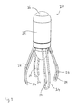
- Fig. 1 illustrates an agitation device 10 which comprises a body portion 12, and four equally spaced stirring elements 14 that depend downwardly from the body portion 12, and a user interface 16 to allow a user to control operation of the agitation device 10.
- the body portion 12 comprises a substantially cylindrical housing and the stirring elements 14 comprise elongate members, the roots of which are spaced equally about the circumference of a lower region of the body portion 12 and, in a normal orientation of the agitation device 10, extend downwardly and radially outward from the body portion 12.
- These stirring elements 14 may be formed from wire, tube, and may comprise prongs, fingers, or elongate "U-shaped" members. As illustrated, the stirring elements 14 also curve inwardly proximate to the ends which are remote from the body portion 12. Thus, in the illustrated arrangement, the stirring elements 14 form a shape similar to a conventional "balloon" whisk.
- the user interface 16 preferably comprises a control switch arranged to allow a user to control operation of the agitation device 10.
- the control switch allows a user to at least switch the agitation device 10 on and off, but preferably additionally allows the user to set at least one of: a frequency of vibration of the agitation device 10 (e.g. speed settings); a period of operation of the agitation device 10 (e.g. a timer); intermittent operation of the agitation device 10; a charging program for a power source of the agitation device 10; and at least one heating and/or cooling operation mode and/or temperature of said agitation device 10.
- a frequency of vibration of the agitation device 10 e.g. speed settings
- a period of operation of the agitation device 10 e.g. a timer
- intermittent operation of the agitation device 10 e.g. a charging program for a power source of the agitation device 10
- the stirring elements 14 are placed in the material(s) to be agitated and the agitation device 10 is arranged to perform an agitating action to: (i) agitate the material(s); and/or (ii) introduce air into the material(s); and/or (iii) dissipate heat.
- This agitating action will be described in more detail in relation to Fig. 4 but, as an initial indication, the action comprises at least one of: a rotational movement of the agitation device 10 within the said material(s); a translational movement of the agitation device 10 through the said materials(s), and an oscillatory movement of the agitation device 10 within the material(s).
- the stirring elements 14 may typically be formed from at least one of: metal; wood; or polymer materials, but are not limited to these materials.
- the stirring elements 14 preferably include features to increase the surface area thereof, e.g. holes, protrusions, extensions, dimples, ridges, etc.
- the stirring elements 14 are each formed with a hole 18 which extends substantially over the length of the stirring element.
- each stirring element may be provided with a different type of surface area enhancing feature to each other stirring element, and each stirring element may comprise more than one surface area enhancing feature.
- the stirring elements 14 are in a "balloon whisk" configuration
- other configurations could be used, e.g. a flat configuration for use in a shallow container, a small diameter for use in narrow containers, or an angled "blade” type configuration (similar to a turbine) to provide lift during rotation.
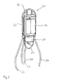
- Fig. 2 illustrates the agitation device 10 of Fig. 1 , but with a portion cut-away to illustrate the internal features of the body portion 12.
- Features common with Fig. 1 are denoted by like reference numerals and will not be described further.
- a motion element 20 and power source 22 comprise internal components located within said body portion 12, and the agitation device 10 further comprises a removable cover 24 forming part of the body portion 12, and arranged for removal to allow access to the motion element 20 and power source 22.
- the removable cover 24 may comprise a screw cap, push cap or clip.
- the motion element 20 in this arrangement comprises an off-centred motor which serves to produce vibrations of the agitation device 10 by causing the agitation device to be constantly off-balance.
- the motion element 20 and power source 22 may be permanently embedded in the body portion 12.
- Fig. 3 illustrates a cut-away view of the agitation device 10. Again, features common with those already described in relation to Figs. 1 and 2 are denoted by like reference numerals and will not be described further.
- a coupling element 26 is provided between power source 22 and motion element 20 and serves to transfer power between said power source 22 and motion element 20.
- the power source 22 comprises an energy storage device and may comprise at least one of: a battery (rechargeable or otherwise); a mechanical energy storage device (such as a flywheel); or a fuel cell.
- a battery rechargeable or otherwise
- a mechanical energy storage device such as a flywheel
- a fuel cell a fuel cell.
- the power source 22 is not limited to the above devices and any other form of storable energy would be suitable.
- the coupling element 26 comprises an electrical contact between power source 22 and motion element 24.
- the coupling element 26 comprises a suitable drive mechanism for transferring energy from the power source 22 to the motion element 24.
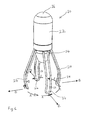
- Fig. 4 illustrates the agitation device 10 according to the present invention when in operation.
- Features common with those already described in relation to Figs. 1 to 3 are denoted by like reference numerals and will not be described further.
- the motion element Upon operation of the user interface 16 by a user to activate the agitation device 10, the motion element (not shown in Fig. 4 ) is activated to produce vibrations which serve to cause movement of the entire agitation device 10.
- Such movement can be one, or a combination of, a rotational movement (as indicated by arrows A) and a translational movement (as indicated by arrows B).
- agitation device 10 when the agitation device 10 is located in a receptacle, for example, a saucepan, with the stirring elements 14 thereof extending into material(s) to be agitated, such movement serves to agitate the material(s) and cause stirring and/or mixing thereof.
- the stirring elements 14 may be at least partly formed from resilient and/or deformable material(s) which serve to transfer vibrations from the body portion 12 (caused by the motion element 20) to the tips of the stirring elements 14. These vibrations of the tips of the stirring elements 14 cause them to move relative to the surface of the container in which the stirring device 10 is located.
- the vibrations produced by the motion element may vary in frequency and the frequency is, preferably, selectable by a user via the user interface 16.
- the frequency of vibrations ranges from infrasonic, through acoustic, to ultrasonic.
- the motion element can comprise a single element, but could also comprise a number of elements.
- the agitation device Whilst the agitation device has been described above as a single-piece device, in an alternative arrangement, it may comprise a separate body portion and stirring elements such that the two items can be detached from one another. In such an alternative arrangement, the stirring elements may move as one with the body portion, or may also move relative to the body portion.
- the single piece device is advantageous in that it allows the device to be stood or inserted entirely into material(s) to be agitated without the risk of liquid ingress.
- the body portion of the agitation device houses the motion element.
- the motion element may be located in the stirring elements or in a detachable separate unit.
- the power source and user interface may be located in the stirring elements or in a detachable separate unit. Further, the user interface may be remotely activated. In any case the user interface is preferably waterproof, either by including a seal around the user interface, or by embedding the user interface under a sealed surface (preferably flexible).
- the body portion and/or stirring elements are formed from shock absorbing material(s).
- these features may be formed from shock neutral or shock enhancing material(s).
- the body portion is designed to fit into the hand of a user to allow manual control of the stirrer.
- the body portion could also be shaped to allow attachment to a further device induing, but not limited to, a mechanical mixer.
- the above described arrangements include an off-centred motor to create vibrations of the agitation device.
- Other arrangements for creating such vibrations may include, but are not limited to: piezoelectric devices; solenoid driven devices; rotary cams; rotary ratchets; and linear ratchets.
- the motion element is not limited to an electric type, but may include any suitable motion device, e.g. manually driven devices.
- An agitating action of the agitation device of the present invention can include mixing and/or stirring actions.
Landscapes
- Chemical & Material Sciences (AREA)
- Chemical Kinetics & Catalysis (AREA)
- Engineering & Computer Science (AREA)
- Mechanical Engineering (AREA)
- Food Science & Technology (AREA)
- Mixers With Rotating Receptacles And Mixers With Vibration Mechanisms (AREA)
- Food-Manufacturing Devices (AREA)
- Mixers Of The Rotary Stirring Type (AREA)
- Confectionery (AREA)
Abstract
Description
- The present invention relates to an agitation device and particularly, but not exclusively, to an agitation device for agitating ingredients in the preparation of food.
- The use of agitation devices in laboratories and various industries such as the building industry (where such agitation devices may be used to agitate, by way of stirring and/or mixing, for example, paints, plaster, concrete/cement, etc), the food industry, etc. is prevalent. Such agitation devices are available with numerous shapes/configurations, such as: turbine type; impeller type; cross-beam type; frame type; blade type; anchor type; pitched-blade type; propeller type; helical ribbon type; whisks, etc, and these agitation devices can be manually powered, electrically powered, mechanically powered, and can be driven directly, or indirectly by way of gears.
- The type of agitation device to be used is dependent upon the material(s) to be agitated. Whisks are particularly suitable for use in both the food industry and for domestic food preparation and their design facilitates mixing, circulation, cooling, stirring of food ingredients, and can allow air to be introduced into the food ingredients.
- In the field of food preparation, agitation devices are chosen not only for ease of aeration and/or mixing of the food ingredients, but also for compatibility with kitchen space, temperature conditions, mixing volumes, the shape and material (e.g. Teflon®) of food mixing vessels, ease of cleaning (e.g. water-proofing or dishwasher suitability), or any combination of these requirements.
- Many known agitation devices for use in food preparation, however, suffer disadvantages in that a fairly quick rotary or "beating" action must often be employed by a user in order to agitate the ingredients of a mixture to obtain a desired consistency/texture of the mixture. This action requires a vigorous rotation of the agitation device applied by way of the user flexing and rotating their wrist. In particularly thick mixtures, the force necessary to agitate the ingredients can cause a user to quickly tire due to fatigue in the wrist region and so it can be difficult for a user to maintain a constant speed of rotation of the agitation device. This issue can be a particular problem in the elderly/infirm or those with weaker wrists.
- Alternative processes for mixing material(s) employ vibrating means to agitate a mixture to cause mixing of the material(s) therein. These processes can employ oscillations to act on the material(s) of the mixture to agitate the mixture. Such processes may employ vibration devices arranged to agitate vats of liquid, etc. in order to facilitate mixing of material(s). The frequency of vibration of such devices may range form infrasonic, through acoustic frequencies, to ultrasonic. These types of processes and devices are employed advantageously where it is desirable to segregate the mixing element from the substance to be mixed or where use of a mixing element may not be possible. For example, an agitation device in which mixing elements of the agitation device have to be physically inserted into a mixture may require measures (e.g. seals) to prevent contamination of the mixture and ingress of material(s) in the mixture to mechanical and/or electrical components of the agitation device and also egress of components of the device and/or lubricating fluids to the material(s) being agitated. Such measures are often expensive and difficult to implement and often are not completely effective so that they are susceptible to liquid ingress. Therefore segregating a motor and vibration technology from the actual elements to be inserted into the mixture is desirable to prevent such contamination and/or ingress/egress problems.
-
DE 10 2004 043579 discloses a hand-held milk-frothing device. -
US 6,015, 225 discloses an apparatus operative for effecting movement of a cement slurry. The apparatus comprises a container which includes an impeller for moving the slurry. The apparatus also includes a vibrator in the container for imparting a vibration to the moving slurry. -
US 6,264,356 discloses a manually operable, hand-held, ball whisk kitchen utensil. - The present invention seeks to provide for an agitation device having advantages over known such agitation devices.
- According to an aspect of the present invention, there is provided an agitation device comprising a body portion and at least one stirring element extending from said body portion and for insertion into material in a receptacle which is to be agitated, wherein the body portion comprises a housing having located therein a motion element powered by way of a power source, and arranged to impart a vibrating action to the device and thus to the said at least one stirring element, characterised by: said at least one stirring element extending from said body portion such that, in normal operation, the at least one stirring element extends downwardly from the body portion and serves to support the device on a surface of the said receptacle and said vibrating action being arranged to effect movement of the agitation device over the said surface and relative to the said material.
- An advantage of the present invention is that the vibrating action of the agitation device and the function of the at least one stirring element as not only an agitating means, but also a support to maintain the agitation device substantially upright, allows the agitation device to be free-standing and, effectively, to automatically agitate or "self agitate" a material by, for example, stirring, mixing, etc. Therefore, the agitation device of the present invention can be used to agitate material(s) itself without requiring a stirring/mixing action applied by a user and without requiring a means to which the agitation device can be fixed, for example, a mixing bowl, in order to provide support for the agitation device and a static feature against which the device can act. Thus, the motion for agitating is generated between the agitation device and the mixing bowl without requiring a fixed point.
- Preferably, the at least one stirring element is integral with the body portion.
- An integral body portion and stirring element means provides an agitation device which comprises a single unit. An advantage of this is that the unit can be manufactured as a single article and so the problem of liquid ingress to the motion element or of the egress of motor parts and/or lubricants to the material, is avoided since there are no seals, etc. which can fail, thereby allowing such ingress/egress.
- Conveniently, said motion element comprises at least one of: an off-centre motor; a piezoelectric driver; a solenoid-driven device; a rotary cam; a rotary ratchet; and a linear ratchet. The frequency of vibration of the motion element may range from infrasonic, through acoustic, to ultrasonic.
- In particular, said at least one stirring element may comprise at least one prong. The at least one prong may comprise surface area enhancing features such as: holes; dimples; and ridges. Also, the at least one stirring element may be at least partly formed of a deformable material to allow the shape/configuration of the at least one stirring element to be altered dependent upon the required use of the agitation device. Additionally, or alternatively, the at least one stirring element may be at least partly formed of a resilient material. Also, the at least one stirring element may be resiliently mounted to the body portion.
- Preferably, said device comprises a plurality of stirring elements which are equally spaced from one another.
- Conveniently, said plurality of stirring elements are in a balloon-type whisk configuration.
- Further, said power source may comprise at least one of: an electrical power source, such as a battery, which may be rechargeable; a mechanical energy source, such as a flywheel or other source of potential mechanical energy, e.g. a spiral spring; a fuel cell; or any other suitable form of storable energy.
- If required, said body portion may be shaped so as to be conveniently gripped by a user. This allows the agitation device to be used as a manual agitation device should the situation require.
- Preferably, said agitation device further comprises heating and/or cooling elements arranged to heat and/or cool said stirring elements.
- By employing a heat source, such as a high resistance process or other, or by employing a cooling source, the stirring elements of said agitation device can be used to heat and/or cool ingredients that are being agitated, and/or affect adhesion of the ingredients to the stirring elements.
- Preferably, the agitation device includes a user interface to enable a user to control operation of the motion element. Conveniently, said user interface comprises a switch including an on/off function. Additionally, the user interface may comprise a variable controller for allowing setting of at least one of: a frequency of vibration of said motion element; a period of operation of said motion element; intermittent operation of said motion element; a charging program for said power source; at least one heating and/or cooling operation mode and/or temperature of said agitation device.
- Preferably, said user interface may be located on said housing of said body portion, but may also be located within said agitation device, or on a stirring element of said agitation device.
- In particular, the agitation device may further comprise a control element, preferably programmable, to allow for setting of different operation modes.
- Additionally, or alternatively, the user interface may be remotely operated. Such remote operation may be implemented by way of near field technology devices which may incorporate infra-red or Bluetooth® technologies.
- Preferably, said movement of the stirring device comprises at least one of: oscillatory movement; rotational movement; and translational movement.
- The present invention is described further hereinafter, by way of example only, with reference to the accompanying drawings in which:
-
Fig. 1 illustrates a perspective view of an agitation device according to the present invention; -
Fig. 2 illustrates a perspective cut-away view of the agitation device ofFig. 1 ; -
Fig. 3 illustrates a cross-sectional side view of the agitation device ofFig. 1 ; and -
Fig. 4 illustrates a perspective view of the agitation device when in operation. - As mentioned,
Fig. 1 illustrates anagitation device 10 which comprises abody portion 12, and four equally spaced stirringelements 14 that depend downwardly from thebody portion 12, and auser interface 16 to allow a user to control operation of theagitation device 10. - In the illustrated embodiment, the
body portion 12 comprises a substantially cylindrical housing and the stirringelements 14 comprise elongate members, the roots of which are spaced equally about the circumference of a lower region of thebody portion 12 and, in a normal orientation of theagitation device 10, extend downwardly and radially outward from thebody portion 12. These stirringelements 14 may be formed from wire, tube, and may comprise prongs, fingers, or elongate "U-shaped" members. As illustrated, thestirring elements 14 also curve inwardly proximate to the ends which are remote from thebody portion 12. Thus, in the illustrated arrangement, thestirring elements 14 form a shape similar to a conventional "balloon" whisk. - The
user interface 16 preferably comprises a control switch arranged to allow a user to control operation of theagitation device 10. The control switch allows a user to at least switch theagitation device 10 on and off, but preferably additionally allows the user to set at least one of: a frequency of vibration of the agitation device 10 (e.g. speed settings); a period of operation of the agitation device 10 (e.g. a timer); intermittent operation of theagitation device 10; a charging program for a power source of theagitation device 10; and at least one heating and/or cooling operation mode and/or temperature of saidagitation device 10. - In use, the stirring
elements 14 are placed in the material(s) to be agitated and theagitation device 10 is arranged to perform an agitating action to: (i) agitate the material(s); and/or (ii) introduce air into the material(s); and/or (iii) dissipate heat. This agitating action will be described in more detail in relation toFig. 4 but, as an initial indication, the action comprises at least one of: a rotational movement of theagitation device 10 within the said material(s); a translational movement of theagitation device 10 through the said materials(s), and an oscillatory movement of theagitation device 10 within the material(s). - The stirring
elements 14 may typically be formed from at least one of: metal; wood; or polymer materials, but are not limited to these materials. - Additionally, the stirring
elements 14 preferably include features to increase the surface area thereof, e.g. holes, protrusions, extensions, dimples, ridges, etc. In the illustrated arrangement, the stirringelements 14 are each formed with ahole 18 which extends substantially over the length of the stirring element. - Of course, each stirring element may be provided with a different type of surface area enhancing feature to each other stirring element, and each stirring element may comprise more than one surface area enhancing feature.
- Whilst in the illustrated arrangement, the stirring
elements 14 are in a "balloon whisk" configuration, other configurations could be used, e.g. a flat configuration for use in a shallow container, a small diameter for use in narrow containers, or an angled "blade" type configuration (similar to a turbine) to provide lift during rotation. -
Fig. 2 illustrates theagitation device 10 ofFig. 1 , but with a portion cut-away to illustrate the internal features of thebody portion 12. Features common withFig. 1 are denoted by like reference numerals and will not be described further. - A
motion element 20 andpower source 22 comprise internal components located within saidbody portion 12, and theagitation device 10 further comprises aremovable cover 24 forming part of thebody portion 12, and arranged for removal to allow access to themotion element 20 andpower source 22. Theremovable cover 24 may comprise a screw cap, push cap or clip. - The
motion element 20 in this arrangement comprises an off-centred motor which serves to produce vibrations of theagitation device 10 by causing the agitation device to be constantly off-balance. - In an alternative arrangement, the
motion element 20 andpower source 22 may be permanently embedded in thebody portion 12. -
Fig. 3 illustrates a cut-away view of theagitation device 10. Again, features common with those already described in relation toFigs. 1 and2 are denoted by like reference numerals and will not be described further. - A
coupling element 26 is provided betweenpower source 22 andmotion element 20 and serves to transfer power between saidpower source 22 andmotion element 20. - The
power source 22 comprises an energy storage device and may comprise at least one of: a battery (rechargeable or otherwise); a mechanical energy storage device (such as a flywheel); or a fuel cell. Of course, thepower source 22 is not limited to the above devices and any other form of storable energy would be suitable. - In the case of the
power source 22 being of an electrical nature, thecoupling element 26 comprises an electrical contact betweenpower source 22 andmotion element 24. Where thepower source 22 is of a mechanical nature, thecoupling element 26 comprises a suitable drive mechanism for transferring energy from thepower source 22 to themotion element 24. -
Fig. 4 illustrates theagitation device 10 according to the present invention when in operation. Features common with those already described in relation toFigs. 1 to 3 are denoted by like reference numerals and will not be described further. - Upon operation of the
user interface 16 by a user to activate theagitation device 10, the motion element (not shown inFig. 4 ) is activated to produce vibrations which serve to cause movement of theentire agitation device 10. Such movement can be one, or a combination of, a rotational movement (as indicated by arrows A) and a translational movement (as indicated by arrows B). - As will be appreciated, when the
agitation device 10 is located in a receptacle, for example, a saucepan, with thestirring elements 14 thereof extending into material(s) to be agitated, such movement serves to agitate the material(s) and cause stirring and/or mixing thereof. - The stirring
elements 14 may be at least partly formed from resilient and/or deformable material(s) which serve to transfer vibrations from the body portion 12 (caused by the motion element 20) to the tips of thestirring elements 14. These vibrations of the tips of thestirring elements 14 cause them to move relative to the surface of the container in which the stirringdevice 10 is located. - The vibrations produced by the motion element may vary in frequency and the frequency is, preferably, selectable by a user via the
user interface 16. In the present embodiment, the frequency of vibrations ranges from infrasonic, through acoustic, to ultrasonic. - The motion element can comprise a single element, but could also comprise a number of elements.
- Whilst the agitation device has been described above as a single-piece device, in an alternative arrangement, it may comprise a separate body portion and stirring elements such that the two items can be detached from one another. In such an alternative arrangement, the stirring elements may move as one with the body portion, or may also move relative to the body portion.
- The single piece device is advantageous in that it allows the device to be stood or inserted entirely into material(s) to be agitated without the risk of liquid ingress.
- Further, and as described above, the body portion of the agitation device houses the motion element. However, in an alternative arrangement, the motion element may be located in the stirring elements or in a detachable separate unit.
- Also, the power source and user interface may be located in the stirring elements or in a detachable separate unit. Further, the user interface may be remotely activated. In any case the user interface is preferably waterproof, either by including a seal around the user interface, or by embedding the user interface under a sealed surface (preferably flexible).
- Preferably, the body portion and/or stirring elements are formed from shock absorbing material(s). Alternatively, these features may be formed from shock neutral or shock enhancing material(s).
- In a convenient arrangement, the body portion is designed to fit into the hand of a user to allow manual control of the stirrer. However, the body portion could also be shaped to allow attachment to a further device induing, but not limited to, a mechanical mixer.
- The above described arrangements include an off-centred motor to create vibrations of the agitation device. Other arrangements for creating such vibrations may include, but are not limited to: piezoelectric devices; solenoid driven devices; rotary cams; rotary ratchets; and linear ratchets.
- It should be understood that the motion element is not limited to an electric type, but may include any suitable motion device, e.g. manually driven devices.
- An agitating action of the agitation device of the present invention can include mixing and/or stirring actions.
Claims (14)
- An agitation device (10) comprising a body portion (12) and at least one stirring element (14) extending from said body portion and for insertion into material in a receptacle which is to be agitated, wherein the body portion comprises a housing having located therein a motion element (20) powered by way of a power source (22), and arranged to impart a vibrating action to the device and thus to the said at least one stirring element, characterised by: said at least one stirring element extending from said body portion such that, in normal operation, the at least one stirring element extends downwardly from the body portion and serves to support the device on a surface of the said receptacle and said vibrating action being arranged to effect movement of the agitation device over the said surface and relative to the said material.
- A device (10) according to Claim 1, wherein the at least one stirring element (14) is integral with the body portion (12).
- A device (10) according to Claim 1 or 2, wherein said motion element (20) comprises at least one of: an off-centre motor; a piezoelectric driver; a solenoid-driven device; a rotary cam; a rotary ratchet; and a linear ratchet; and optionally wherein a frequency of vibration of the motion element may range from infrasonic, through acoustic, to ultrasonic.
- A device (10) according to any one or more of the preceding claims, wherein the at least one stirring element (14) comprise prongs; and optionally wherein the prongs comprise surface area enhancing features; and optionally wherein said surface area enhancing features comprise at least one of: holes (18); protrusions; extensions; dimples; ridges.
- A device (10) according to any one or more of the preceding claims, wherein the said at least one stirring element (14) is at least partly formed of a deformable material; and optionally a resilient material; and optionally are resiliently mounted to the body portion (12).
- A device (10) according to any one or more of the preceding claims wherein the said at least one stirring element (14) has a balloon-type whisk configuration.
- A device (10) according to any one or more of the preceding claims, wherein a power source (22) of the agitation device comprises at least one of: an electrical power source; a mechanical energy source; and a fuel cell.
- A device (10) according to any one or more of the preceding claims, further comprising a user interface (16) to enable a user to control operation of the motion element (20); and optionally wherein said user interface comprises a switch including an on/off function.
- A device (10) according to Claim 8, wherein the user interface (16) comprises a variable controller for allowing setting of at least one of: a frequency of vibration of said motion element (20); a period of operation of said motion element; intermittent operation of said motion element; a charging program for said power source (22); at least one heating and/or cooling operation mode and/or temperature of said agitation device.
- A device (10) according to Claim 8 or 9, wherein said user interface (16) is located on said housing of said body portion (12); or optionally wherein said user interface is located within said agitation device; or optionally wherein said user interface is located on a stirring element (14) of said agitation device.
- A device (10) according to any one or more of Claims 8 to 10, wherein said user interface (16) is arranged for remote operation.
- A device (10) according to any one or more of the preceding claims, further comprising a programmable control element to allow for setting of different operation modes.
- A device (10) according to any one or more of the preceding claims, wherein said movement of the device comprises at least one of: oscillatory movement; rotational movement; and translational movement.
- A device (10) according to any one or more of the preceding claims, further comprising heating and/or cooling elements arranged to heat and/or cool said stirring elements (14).
Applications Claiming Priority (2)
| Application Number | Priority Date | Filing Date | Title |
|---|---|---|---|
| GB0722006A GB2454503A (en) | 2007-11-09 | 2007-11-09 | Vibrating stirrer |
| PCT/GB2008/051034 WO2009060236A2 (en) | 2007-11-09 | 2008-11-06 | Agitation device |
Publications (2)
| Publication Number | Publication Date |
|---|---|
| EP2214812A2 EP2214812A2 (en) | 2010-08-11 |
| EP2214812B1 true EP2214812B1 (en) | 2011-10-12 |
Family
ID=38858423
Family Applications (1)
| Application Number | Title | Priority Date | Filing Date |
|---|---|---|---|
| EP08846978A Active EP2214812B1 (en) | 2007-11-09 | 2008-11-06 | Agitation device |
Country Status (7)
| Country | Link |
|---|---|
| US (2) | US8313228B2 (en) |
| EP (1) | EP2214812B1 (en) |
| AT (1) | ATE528067T1 (en) |
| DK (1) | DK2214812T3 (en) |
| ES (1) | ES2375456T3 (en) |
| GB (1) | GB2454503A (en) |
| WO (1) | WO2009060236A2 (en) |
Families Citing this family (11)
| Publication number | Priority date | Publication date | Assignee | Title |
|---|---|---|---|---|
| GB2492412A (en) * | 2011-07-01 | 2013-01-02 | And Design Ltd | Agitation device |
| USD719198S1 (en) * | 2013-02-15 | 2014-12-09 | Kazuo Tsuchiya | Agitating rotor |
| USD719197S1 (en) * | 2013-02-15 | 2014-12-09 | Kazuo Tsuchiya | Agitating rotor |
| CA156862S (en) * | 2013-12-04 | 2015-01-14 | Outotec Finland Oy | Impeller for hydrometallurgical mixer |
| CA157702S (en) * | 2014-01-29 | 2015-04-27 | Fiskars Home Oy Ab | Ball whisk |
| US10099187B2 (en) | 2015-09-08 | 2018-10-16 | Adip Management, Llc | Mixing systems and methods |
| US10213053B2 (en) | 2015-09-08 | 2019-02-26 | Adip Management, Llc | Whisk mixing systems within a container |
| US20210235936A1 (en) * | 2018-08-09 | 2021-08-05 | Kinetic Ideations, Inc. | Agitator for brewing, steeping or infusing a liquid |
| CN109603604A (en) * | 2018-12-14 | 2019-04-12 | 徐州蓝湖信息科技有限公司 | A kind of industrial coating mixing automatic stirrer |
| USD953388S1 (en) * | 2019-08-30 | 2022-05-31 | Kazuo Sato | Food industry machine |
| US11641979B2 (en) * | 2020-11-12 | 2023-05-09 | DanDre Technology Innovation Limited | Culinary whisk |
Family Cites Families (30)
| Publication number | Priority date | Publication date | Assignee | Title |
|---|---|---|---|---|
| US335739A (en) * | 1886-02-09 | Churn | ||
| US427963A (en) * | 1890-05-13 | Sylvania | ||
| US1723091A (en) * | 1928-08-11 | 1929-08-06 | John Henry W St | Golf accessory |
| US2092353A (en) * | 1936-04-30 | 1937-09-07 | George L Kyseth | Stirring device |
| US2214142A (en) * | 1938-04-06 | 1940-09-10 | Mall Arthur William | Vibrator |
| US2445196A (en) * | 1944-06-21 | 1948-07-13 | P R Maliory & Co Inc | Sealed vibrator |
| US2544248A (en) * | 1948-06-22 | 1951-03-06 | Frances O Ashmead | Nail file vibrator device |
| NL83008C (en) * | 1951-04-28 | |||
| US3259272A (en) * | 1964-06-19 | 1966-07-05 | Korad Corp | Method and apparatus for dispensing powder |
| ZA735688B (en) * | 1973-08-17 | 1975-07-30 | A Drynan | Mechanical device for mixing and blending substances |
| FR2315311A1 (en) * | 1975-06-23 | 1977-01-21 | Drynan Anthony | Mechanical blender - comprising body portion, and number of vibrating prongs |
| US4252444A (en) * | 1978-08-28 | 1981-02-24 | L. B. Foster Company | Apparatus for agitating liquids |
| US4778279A (en) * | 1987-08-20 | 1988-10-18 | Bodine Albert G | Sonic agitator with multi phased vibration bars |
| JPH024434A (en) * | 1988-06-22 | 1990-01-09 | Akai Electric Co Ltd | Ultrasonic mixer |
| US5476321A (en) * | 1995-04-05 | 1995-12-19 | Mcnaughton; Betty | Container stirring device |
| JP3630834B2 (en) * | 1995-04-24 | 2005-03-23 | 株式会社リコー | Method for mixing two or more kinds of resin raw material liquids and mixing apparatus therefor |
| US5725304A (en) * | 1995-12-13 | 1998-03-10 | Makita Corporation | Battery concrete vibrator |
| US5630666A (en) * | 1996-03-04 | 1997-05-20 | Rodriguez; Ernesto | Cone-shaped paint container |
| US6015225A (en) | 1996-03-13 | 2000-01-18 | Matrix Master Inc. | Vibration input to moving aqueous cementitious slurry |
| JP3756296B2 (en) * | 1997-08-20 | 2006-03-15 | 株式会社東芝 | Stirrer |
| US6334705B1 (en) * | 1998-10-01 | 2002-01-01 | General Signal Corporation | Fluid mixing impellers with shear generating venturi |
| US6068395A (en) * | 1998-12-09 | 2000-05-30 | Ondracek; John | Pot stirring device with s-shaped stirring blades |
| US6264356B1 (en) | 2000-04-03 | 2001-07-24 | Wmf Ag | Ball whisk kitchen utensil |
| CA2439667A1 (en) * | 2003-09-04 | 2005-03-04 | Andrew Kenneth Hoffmann | Low frequency vibration assisted blood perfusion system and apparatus |
| DE102004043579A1 (en) | 2004-11-23 | 2006-05-24 | Katthöfer, Torsten | Hand attachment e.g. for milk creamer, has rechargeable batteries, either permanently fitted or removable and charging of batteries is performed when attachment is placed into loading station |
| USD524886S1 (en) * | 2005-04-13 | 2006-07-11 | Maurice Baril | Golf ball picker |
| US7578611B2 (en) * | 2005-10-14 | 2009-08-25 | Ralph Hamilton | Stirrer tool with radially and distally extending flexible projections |
| USD575597S1 (en) * | 2007-05-08 | 2008-08-26 | Gavin Reay | Whisk |
| USD576186S1 (en) * | 2007-07-31 | 2008-09-02 | United States Gypsum Company | Mixer for viscous materials |
| USD617135S1 (en) * | 2008-02-28 | 2010-06-08 | Gavin Reay | Mixer |
-
2007
- 2007-11-09 GB GB0722006A patent/GB2454503A/en not_active Withdrawn
-
2008
- 2008-11-06 WO PCT/GB2008/051034 patent/WO2009060236A2/en not_active Ceased
- 2008-11-06 ES ES08846978T patent/ES2375456T3/en active Active
- 2008-11-06 AT AT08846978T patent/ATE528067T1/en not_active IP Right Cessation
- 2008-11-06 EP EP08846978A patent/EP2214812B1/en active Active
- 2008-11-06 DK DK08846978.8T patent/DK2214812T3/en active
-
2009
- 2009-09-10 US US12/556,744 patent/US8313228B2/en not_active Expired - Fee Related
-
2010
- 2010-04-14 US US29/359,688 patent/USD625747S1/en not_active Expired - Lifetime
Also Published As
| Publication number | Publication date |
|---|---|
| WO2009060236A3 (en) | 2009-08-13 |
| EP2214812A2 (en) | 2010-08-11 |
| ES2375456T3 (en) | 2012-03-01 |
| US20100074046A1 (en) | 2010-03-25 |
| DK2214812T3 (en) | 2012-02-06 |
| ATE528067T1 (en) | 2011-10-15 |
| WO2009060236A2 (en) | 2009-05-14 |
| USD625747S1 (en) | 2010-10-19 |
| GB2454503A (en) | 2009-05-13 |
| GB0722006D0 (en) | 2007-12-19 |
| US8313228B2 (en) | 2012-11-20 |
Similar Documents
| Publication | Publication Date | Title |
|---|---|---|
| US8313228B2 (en) | Agitation device | |
| US20140140163A1 (en) | Agitation device | |
| CN110461199B (en) | Stirring volume reduction device | |
| EP3264955B1 (en) | Mixer apparatus and method | |
| JP5675603B2 (en) | Stirrer and mixing device equipped with stirrer | |
| CN101203165A (en) | Self-stirring, heating and cooking unit with interchangeable stirring devices | |
| CN210330373U (en) | Stirring accessories and household appliances for cooking preparations including the same | |
| AU2010343382A1 (en) | Device for agitating liquid foodstuff | |
| EP2338394A1 (en) | Beater assembly and kitchen appliance with a beater assembly | |
| CN108324146B (en) | multifunctional food processor | |
| CN1271259A (en) | Accessories for preparing emulsion, foams and dispersions and electrical household, or domestic, appliance for cooking | |
| GB2129322A (en) | Detachable stirring device | |
| CN210330378U (en) | Stirring accessory and household cooking appliance comprising same | |
| CN100421607C (en) | Whisk dish for kitchen utensils | |
| JP2013090890A (en) | Cooking utensil with stirring device and the stirring device | |
| GB2492412A (en) | Agitation device | |
| KR102420713B1 (en) | Smart cookware | |
| CN104883941B (en) | The container of food can wherein be heated | |
| CN106455585A (en) | Household appliance mixing arrangement | |
| KR20060070261A (en) | Agitator for food cooking | |
| US5938331A (en) | Automatic stirring apparatus | |
| EP3569117B1 (en) | Food processor | |
| CN212261198U (en) | Shake egg mechanism and have cooking machine who shakes egg mechanism | |
| CN211961839U (en) | Household appliance for processing food | |
| KR200379411Y1 (en) | Agitator for cooking |
Legal Events
| Date | Code | Title | Description |
|---|---|---|---|
| PUAI | Public reference made under article 153(3) epc to a published international application that has entered the european phase |
Free format text: ORIGINAL CODE: 0009012 |
|
| 17P | Request for examination filed |
Effective date: 20100326 |
|
| AK | Designated contracting states |
Kind code of ref document: A2 Designated state(s): AT BE BG CH CY CZ DE DK EE ES FI FR GB GR HR HU IE IS IT LI LT LU LV MC MT NL NO PL PT RO SE SI SK TR |
|
| AX | Request for extension of the european patent |
Extension state: AL BA MK RS |
|
| 17Q | First examination report despatched |
Effective date: 20101027 |
|
| GRAP | Despatch of communication of intention to grant a patent |
Free format text: ORIGINAL CODE: EPIDOSNIGR1 |
|
| GRAS | Grant fee paid |
Free format text: ORIGINAL CODE: EPIDOSNIGR3 |
|
| GRAA | (expected) grant |
Free format text: ORIGINAL CODE: 0009210 |
|
| AK | Designated contracting states |
Kind code of ref document: B1 Designated state(s): AT BE BG CH CY CZ DE DK EE ES FI FR GB GR HR HU IE IS IT LI LT LU LV MC MT NL NO PL PT RO SE SI SK TR |
|
| REG | Reference to a national code |
Ref country code: GB Ref legal event code: FG4D |
|
| REG | Reference to a national code |
Ref country code: CH Ref legal event code: EP |
|
| REG | Reference to a national code |
Ref country code: IE Ref legal event code: FG4D |
|
| REG | Reference to a national code |
Ref country code: DE Ref legal event code: R096 Ref document number: 602008010490 Country of ref document: DE Effective date: 20111215 |
|
| REG | Reference to a national code |
Ref country code: CH Ref legal event code: NV Representative=s name: NOVAGRAAF INTERNATIONAL SA |
|
| REG | Reference to a national code |
Ref country code: SE Ref legal event code: TRGR |
|
| REG | Reference to a national code |
Ref country code: NL Ref legal event code: T3 |
|
| REG | Reference to a national code |
Ref country code: NO Ref legal event code: T2 Effective date: 20111012 |
|
| REG | Reference to a national code |
Ref country code: DK Ref legal event code: T3 |
|
| REG | Reference to a national code |
Ref country code: ES Ref legal event code: FG2A Ref document number: 2375456 Country of ref document: ES Kind code of ref document: T3 Effective date: 20120301 |
|
| LTIE | Lt: invalidation of european patent or patent extension |
Effective date: 20111012 |
|
| REG | Reference to a national code |
Ref country code: AT Ref legal event code: MK05 Ref document number: 528067 Country of ref document: AT Kind code of ref document: T Effective date: 20111012 |
|
| PG25 | Lapsed in a contracting state [announced via postgrant information from national office to epo] |
Ref country code: IS Free format text: LAPSE BECAUSE OF FAILURE TO SUBMIT A TRANSLATION OF THE DESCRIPTION OR TO PAY THE FEE WITHIN THE PRESCRIBED TIME-LIMIT Effective date: 20120212 Ref country code: LT Free format text: LAPSE BECAUSE OF FAILURE TO SUBMIT A TRANSLATION OF THE DESCRIPTION OR TO PAY THE FEE WITHIN THE PRESCRIBED TIME-LIMIT Effective date: 20111012 Ref country code: BE Free format text: LAPSE BECAUSE OF FAILURE TO SUBMIT A TRANSLATION OF THE DESCRIPTION OR TO PAY THE FEE WITHIN THE PRESCRIBED TIME-LIMIT Effective date: 20111012 |
|
| PG25 | Lapsed in a contracting state [announced via postgrant information from national office to epo] |
Ref country code: LV Free format text: LAPSE BECAUSE OF FAILURE TO SUBMIT A TRANSLATION OF THE DESCRIPTION OR TO PAY THE FEE WITHIN THE PRESCRIBED TIME-LIMIT Effective date: 20111012 Ref country code: GR Free format text: LAPSE BECAUSE OF FAILURE TO SUBMIT A TRANSLATION OF THE DESCRIPTION OR TO PAY THE FEE WITHIN THE PRESCRIBED TIME-LIMIT Effective date: 20120113 Ref country code: HR Free format text: LAPSE BECAUSE OF FAILURE TO SUBMIT A TRANSLATION OF THE DESCRIPTION OR TO PAY THE FEE WITHIN THE PRESCRIBED TIME-LIMIT Effective date: 20111012 Ref country code: SI Free format text: LAPSE BECAUSE OF FAILURE TO SUBMIT A TRANSLATION OF THE DESCRIPTION OR TO PAY THE FEE WITHIN THE PRESCRIBED TIME-LIMIT Effective date: 20111012 Ref country code: PT Free format text: LAPSE BECAUSE OF FAILURE TO SUBMIT A TRANSLATION OF THE DESCRIPTION OR TO PAY THE FEE WITHIN THE PRESCRIBED TIME-LIMIT Effective date: 20120213 |
|
| PG25 | Lapsed in a contracting state [announced via postgrant information from national office to epo] |
Ref country code: CY Free format text: LAPSE BECAUSE OF FAILURE TO SUBMIT A TRANSLATION OF THE DESCRIPTION OR TO PAY THE FEE WITHIN THE PRESCRIBED TIME-LIMIT Effective date: 20111012 Ref country code: MC Free format text: LAPSE BECAUSE OF NON-PAYMENT OF DUE FEES Effective date: 20111130 |
|
| PG25 | Lapsed in a contracting state [announced via postgrant information from national office to epo] |
Ref country code: CZ Free format text: LAPSE BECAUSE OF FAILURE TO SUBMIT A TRANSLATION OF THE DESCRIPTION OR TO PAY THE FEE WITHIN THE PRESCRIBED TIME-LIMIT Effective date: 20111012 Ref country code: EE Free format text: LAPSE BECAUSE OF FAILURE TO SUBMIT A TRANSLATION OF THE DESCRIPTION OR TO PAY THE FEE WITHIN THE PRESCRIBED TIME-LIMIT Effective date: 20111012 Ref country code: BG Free format text: LAPSE BECAUSE OF FAILURE TO SUBMIT A TRANSLATION OF THE DESCRIPTION OR TO PAY THE FEE WITHIN THE PRESCRIBED TIME-LIMIT Effective date: 20120112 Ref country code: SK Free format text: LAPSE BECAUSE OF FAILURE TO SUBMIT A TRANSLATION OF THE DESCRIPTION OR TO PAY THE FEE WITHIN THE PRESCRIBED TIME-LIMIT Effective date: 20111012 |
|
| PLBE | No opposition filed within time limit |
Free format text: ORIGINAL CODE: 0009261 |
|
| STAA | Information on the status of an ep patent application or granted ep patent |
Free format text: STATUS: NO OPPOSITION FILED WITHIN TIME LIMIT |
|
| REG | Reference to a national code |
Ref country code: IE Ref legal event code: MM4A |
|
| PG25 | Lapsed in a contracting state [announced via postgrant information from national office to epo] |
Ref country code: RO Free format text: LAPSE BECAUSE OF FAILURE TO SUBMIT A TRANSLATION OF THE DESCRIPTION OR TO PAY THE FEE WITHIN THE PRESCRIBED TIME-LIMIT Effective date: 20111012 Ref country code: PL Free format text: LAPSE BECAUSE OF FAILURE TO SUBMIT A TRANSLATION OF THE DESCRIPTION OR TO PAY THE FEE WITHIN THE PRESCRIBED TIME-LIMIT Effective date: 20111012 |
|
| 26N | No opposition filed |
Effective date: 20120713 |
|
| PG25 | Lapsed in a contracting state [announced via postgrant information from national office to epo] |
Ref country code: IE Free format text: LAPSE BECAUSE OF NON-PAYMENT OF DUE FEES Effective date: 20111106 |
|
| REG | Reference to a national code |
Ref country code: DE Ref legal event code: R097 Ref document number: 602008010490 Country of ref document: DE Effective date: 20120713 |
|
| PG25 | Lapsed in a contracting state [announced via postgrant information from national office to epo] |
Ref country code: AT Free format text: LAPSE BECAUSE OF FAILURE TO SUBMIT A TRANSLATION OF THE DESCRIPTION OR TO PAY THE FEE WITHIN THE PRESCRIBED TIME-LIMIT Effective date: 20111012 |
|
| PG25 | Lapsed in a contracting state [announced via postgrant information from national office to epo] |
Ref country code: MT Free format text: LAPSE BECAUSE OF FAILURE TO SUBMIT A TRANSLATION OF THE DESCRIPTION OR TO PAY THE FEE WITHIN THE PRESCRIBED TIME-LIMIT Effective date: 20111012 |
|
| PG25 | Lapsed in a contracting state [announced via postgrant information from national office to epo] |
Ref country code: LU Free format text: LAPSE BECAUSE OF NON-PAYMENT OF DUE FEES Effective date: 20111106 |
|
| PG25 | Lapsed in a contracting state [announced via postgrant information from national office to epo] |
Ref country code: FI Free format text: LAPSE BECAUSE OF FAILURE TO SUBMIT A TRANSLATION OF THE DESCRIPTION OR TO PAY THE FEE WITHIN THE PRESCRIBED TIME-LIMIT Effective date: 20111012 |
|
| PG25 | Lapsed in a contracting state [announced via postgrant information from national office to epo] |
Ref country code: HU Free format text: LAPSE BECAUSE OF FAILURE TO SUBMIT A TRANSLATION OF THE DESCRIPTION OR TO PAY THE FEE WITHIN THE PRESCRIBED TIME-LIMIT Effective date: 20111012 |
|
| REG | Reference to a national code |
Ref country code: FR Ref legal event code: PLFP Year of fee payment: 8 |
|
| REG | Reference to a national code |
Ref country code: FR Ref legal event code: PLFP Year of fee payment: 9 |
|
| REG | Reference to a national code |
Ref country code: FR Ref legal event code: PLFP Year of fee payment: 10 |
|
| PGFP | Annual fee paid to national office [announced via postgrant information from national office to epo] |
Ref country code: NL Payment date: 20171116 Year of fee payment: 10 Ref country code: DK Payment date: 20171115 Year of fee payment: 10 Ref country code: TR Payment date: 20171030 Year of fee payment: 10 Ref country code: FR Payment date: 20171115 Year of fee payment: 10 |
|
| PGFP | Annual fee paid to national office [announced via postgrant information from national office to epo] |
Ref country code: SE Payment date: 20171116 Year of fee payment: 10 Ref country code: IT Payment date: 20171121 Year of fee payment: 10 Ref country code: ES Payment date: 20171204 Year of fee payment: 10 Ref country code: CH Payment date: 20171120 Year of fee payment: 10 |
|
| REG | Reference to a national code |
Ref country code: DK Ref legal event code: EBP Effective date: 20181130 |
|
| REG | Reference to a national code |
Ref country code: CH Ref legal event code: PL |
|
| REG | Reference to a national code |
Ref country code: SE Ref legal event code: EUG |
|
| REG | Reference to a national code |
Ref country code: NL Ref legal event code: MM Effective date: 20181201 |
|
| PG25 | Lapsed in a contracting state [announced via postgrant information from national office to epo] |
Ref country code: SE Free format text: LAPSE BECAUSE OF NON-PAYMENT OF DUE FEES Effective date: 20181107 |
|
| PG25 | Lapsed in a contracting state [announced via postgrant information from national office to epo] |
Ref country code: NL Free format text: LAPSE BECAUSE OF NON-PAYMENT OF DUE FEES Effective date: 20181201 Ref country code: LI Free format text: LAPSE BECAUSE OF NON-PAYMENT OF DUE FEES Effective date: 20181130 Ref country code: CH Free format text: LAPSE BECAUSE OF NON-PAYMENT OF DUE FEES Effective date: 20181130 |
|
| PG25 | Lapsed in a contracting state [announced via postgrant information from national office to epo] |
Ref country code: FR Free format text: LAPSE BECAUSE OF NON-PAYMENT OF DUE FEES Effective date: 20181130 Ref country code: IT Free format text: LAPSE BECAUSE OF NON-PAYMENT OF DUE FEES Effective date: 20181106 Ref country code: DK Free format text: LAPSE BECAUSE OF NON-PAYMENT OF DUE FEES Effective date: 20181130 |
|
| REG | Reference to a national code |
Ref country code: ES Ref legal event code: FD2A Effective date: 20200102 |
|
| PG25 | Lapsed in a contracting state [announced via postgrant information from national office to epo] |
Ref country code: ES Free format text: LAPSE BECAUSE OF NON-PAYMENT OF DUE FEES Effective date: 20181107 |
|
| REG | Reference to a national code |
Ref country code: DE Ref legal event code: R082 Ref document number: 602008010490 Country of ref document: DE Representative=s name: STOLMAR & PARTNER PATENTANWAELTE PARTG MBB, DE |
|
| REG | Reference to a national code |
Ref country code: DE Ref legal event code: R079 Ref document number: 602008010490 Country of ref document: DE Free format text: PREVIOUS MAIN CLASS: B01F0011000000 Ipc: B01F0031000000 |
|
| PG25 | Lapsed in a contracting state [announced via postgrant information from national office to epo] |
Ref country code: TR Free format text: LAPSE BECAUSE OF NON-PAYMENT OF DUE FEES Effective date: 20181106 |
|
| PGFP | Annual fee paid to national office [announced via postgrant information from national office to epo] |
Ref country code: DE Payment date: 20251201 Year of fee payment: 18 |
|
| PGFP | Annual fee paid to national office [announced via postgrant information from national office to epo] |
Ref country code: GB Payment date: 20251127 Year of fee payment: 18 |
|
| PGFP | Annual fee paid to national office [announced via postgrant information from national office to epo] |
Ref country code: NO Payment date: 20251202 Year of fee payment: 18 |