EP2213625B1 - Elektrolysevorrichtung - Google Patents
Elektrolysevorrichtung Download PDFInfo
- Publication number
- EP2213625B1 EP2213625B1 EP10150248.2A EP10150248A EP2213625B1 EP 2213625 B1 EP2213625 B1 EP 2213625B1 EP 10150248 A EP10150248 A EP 10150248A EP 2213625 B1 EP2213625 B1 EP 2213625B1
- Authority
- EP
- European Patent Office
- Prior art keywords
- acidic
- basic
- channel
- cartridge
- water
- Prior art date
- Legal status (The legal status is an assumption and is not a legal conclusion. Google has not performed a legal analysis and makes no representation as to the accuracy of the status listed.)
- Not-in-force
Links
- 238000005868 electrolysis reaction Methods 0.000 title claims description 57
- XLYOFNOQVPJJNP-UHFFFAOYSA-N water Substances O XLYOFNOQVPJJNP-UHFFFAOYSA-N 0.000 claims description 71
- 230000002378 acidificating effect Effects 0.000 claims description 46
- 238000005406 washing Methods 0.000 claims description 6
- 238000005342 ion exchange Methods 0.000 claims description 5
- 230000005611 electricity Effects 0.000 claims description 3
- 238000009434 installation Methods 0.000 description 9
- VEXZGXHMUGYJMC-UHFFFAOYSA-N Hydrochloric acid Chemical compound Cl VEXZGXHMUGYJMC-UHFFFAOYSA-N 0.000 description 4
- 239000003014 ion exchange membrane Substances 0.000 description 2
- 239000012528 membrane Substances 0.000 description 2
- 238000000034 method Methods 0.000 description 2
- 125000006850 spacer group Chemical group 0.000 description 2
- 230000004888 barrier function Effects 0.000 description 1
- 230000003247 decreasing effect Effects 0.000 description 1
- 230000002349 favourable effect Effects 0.000 description 1
- 238000001914 filtration Methods 0.000 description 1
- 239000012530 fluid Substances 0.000 description 1
- 238000004519 manufacturing process Methods 0.000 description 1
- 239000002245 particle Substances 0.000 description 1
- 238000000926 separation method Methods 0.000 description 1
- 239000007787 solid Substances 0.000 description 1
Images




Classifications
-
- C—CHEMISTRY; METALLURGY
- C02—TREATMENT OF WATER, WASTE WATER, SEWAGE, OR SLUDGE
- C02F—TREATMENT OF WATER, WASTE WATER, SEWAGE, OR SLUDGE
- C02F1/00—Treatment of water, waste water, or sewage
- C02F1/46—Treatment of water, waste water, or sewage by electrochemical methods
- C02F1/461—Treatment of water, waste water, or sewage by electrochemical methods by electrolysis
- C02F1/46104—Devices therefor; Their operating or servicing
- C02F1/4618—Devices therefor; Their operating or servicing for producing "ionised" acidic or basic water
-
- C—CHEMISTRY; METALLURGY
- C02—TREATMENT OF WATER, WASTE WATER, SEWAGE, OR SLUDGE
- C02F—TREATMENT OF WATER, WASTE WATER, SEWAGE, OR SLUDGE
- C02F1/00—Treatment of water, waste water, or sewage
- C02F1/46—Treatment of water, waste water, or sewage by electrochemical methods
- C02F1/461—Treatment of water, waste water, or sewage by electrochemical methods by electrolysis
- C02F1/46104—Devices therefor; Their operating or servicing
-
- C—CHEMISTRY; METALLURGY
- C02—TREATMENT OF WATER, WASTE WATER, SEWAGE, OR SLUDGE
- C02F—TREATMENT OF WATER, WASTE WATER, SEWAGE, OR SLUDGE
- C02F1/00—Treatment of water, waste water, or sewage
- C02F1/46—Treatment of water, waste water, or sewage by electrochemical methods
- C02F1/461—Treatment of water, waste water, or sewage by electrochemical methods by electrolysis
- C02F1/46104—Devices therefor; Their operating or servicing
- C02F1/46109—Electrodes
- C02F2001/46152—Electrodes characterised by the shape or form
-
- C—CHEMISTRY; METALLURGY
- C02—TREATMENT OF WATER, WASTE WATER, SEWAGE, OR SLUDGE
- C02F—TREATMENT OF WATER, WASTE WATER, SEWAGE, OR SLUDGE
- C02F2201/00—Apparatus for treatment of water, waste water or sewage
- C02F2201/46—Apparatus for electrochemical processes
- C02F2201/461—Electrolysis apparatus
- C02F2201/46105—Details relating to the electrolytic devices
- C02F2201/46115—Electrolytic cell with membranes or diaphragms
-
- C—CHEMISTRY; METALLURGY
- C02—TREATMENT OF WATER, WASTE WATER, SEWAGE, OR SLUDGE
- C02F—TREATMENT OF WATER, WASTE WATER, SEWAGE, OR SLUDGE
- C02F2201/00—Apparatus for treatment of water, waste water or sewage
- C02F2201/46—Apparatus for electrochemical processes
- C02F2201/461—Electrolysis apparatus
- C02F2201/46105—Details relating to the electrolytic devices
- C02F2201/4612—Controlling or monitoring
- C02F2201/46145—Fluid flow
Definitions
- This invention relates to a device which forms acidic and basic water by electrolyzing mains water used in washing machines.
- the water electrolysis system described in the patent document numbered US2002027070 comprises an electronic cell, a perforated pipe which enables water entry inside the cell, at least one anode plate extending vertically inside the cell, at least one cathode plate positioned inside the cell in parallel with the anode plate and an outlet pipe which delivers the electrolyzed water out of the cell.
- the cathode has a perforated structure to permit water passage. A small channel is situated between the anode and the cathode plates. In this system, a precaution which prevents the electrolyzed acidic and the basic water to mix with each other is not present.
- the industrial electrolysis washing machine described in the patent application numbered W02004065682 comprises an electrolysis device composed of one anode plate and one cathode plate situated on both sides of the ion exchange membrane.
- the anode and cathode is structured as a plate in order to increase the contact surface whereby the efficiency of the electrolysis is also increased.
- This invention is not favourable as its production is complex and costly and also as it occupies a lot of space.
- the patent application JP 8 332486A describes a compact electrolysis apparatus with a plurality of electrolysis cells in which plate like electrodes sandwich two spacers and a barrier membrane.
- the water to be treated is distributed by a pipe to the feed ports of the parallel cells.
- the spacers allow a meander-type flow of the fluid under treatment.
- the system described in the patent application numbered US6126796 comprises an electrolytic cell.
- Ion exchange membrane between the anode and cathode is present in the system which comprises a power supply that supplies electricity to the anode and cathode.
- the hydrochloric acid is added to the anode via membrane whereby the catholyte and the anolyte remains acidic. In this system only acidic water is obtained and there is a need to add hydrochloric acid to the system.
- the electrolysis device of claim 1 which is the subject of the invention and the details of which are described below comprises a lower cap, an upper cap, at least two diffuser and electrolysis cells.
- An electrolysis cell comprises two cartridges situated between at least two electrodes located at the outermost and which function as an anode and a cathode respectively and a separator located at the midmost which solely permits ion exchange. Cells are arranged in such a way that the cartridges and the separator of the other cells are placed next to the electrode located at the outermost. In this way, while the surface of one electrode functions as an anode, it functions as a cathode for the cell located at the other surface.
- the mains water is delivered to the electrolysis cell through a hole perforated on the side surface of the lower cap.
- the even distribution of the mains water through the electrolysis cells is enabled by two structurally different diffusers located between the water entry hole and the electrolysis cell.
- the mains water which is separated as acidic and basic water by being passed through an electrolysis cell, passes through the exit holes located on any of the side surfaces of the lower cap. In this way, the electrolysis process is completed.
- the electrolysis cells are fixed horizontally by fixing together the lower cap and the upper cap with screws.
- the protrusions located at the lower cap wherein the diffuser is arranged form the lower base for the electrolysis cells and thus enable the cells to be fixed vertically.
- the electrolysis cell comprises two plate shaped electrodes facing each other on the outermost section; an acidic water exit hole and a basic water exit hole in plate form and perforated structure which are positioned such that they correspond to the surfaces of the electrodes facing each other, which have a mid section separated with columns, which are perforated separately from each other at one end such that one is slightly higher than the other horizontally and vertically; a discharge channel which extends, on the corresponding surfaces, from the hole to the acidic water exit hole on one and from the hole to the basic water exit hole on the other; tie pieces which are formed, excluding the circumference of the discharge channel, around the acidic and basic water exit holes that have discharge channels and which ensure that the channelled perforations are firmly tied to the unchanneled perforations by fixing the channelled perforations to the unchanneled perforations; acidic and basic cartridges having drain channels opening into the inner surface of the last column located at the other end of the plate; a separator which prevents mixing of acidic and basic water between the acidic and basic
- an electrode functions as an anode for a cell present on one of its surface and functions as a cathode for a cell present on its other surface.
- the object of the invention is to obtain acidic and basic water by electrolyzing mains water.
- Another object of the invention is to obtain the desired voltage in each electrolysis cell by changing the number of the electrolysis cells without using any voltage adjustment device.
- Yet another object of the invention is to ensure separation of acidic and basic water by preventing them to be mixed with each other.
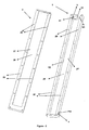
- the top perspective views of the lower cap (1) and the upper cap (2) of the electrolysis device (A) are shown in figure 1 in an assembled state and in a disassembled state in Figure 2 .
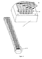
- Figure 3 and Figure 4 show top perspective views of the assembled state of the electrolysis cells (23) and the diffuser (7).
- the electrolysis device (A) shown in figures 1-4 which is the subject of the invention and which is utilized to separate mains water used in washing machines into acidic and basic water by means of electrolysis, comprises a lower cap (1), an upper cap (2), at least one diffuser (7) and electrolysis cells (23).
- an upper cap (2) which has sides (26) that form a channel (28) at the mid section of the inner surface (27) and which has installation holes (20) on the upper surface of the sides (26); and a lower cap (1) which has sides (26') that form a channel (28') at the mid section of the inner surface (27'), which is provided with installation holes (20) on its sides being formed so as to correspond with the installation holes (20) located on the upper cap (2), which comprises a slot (21) being formed at one end of the channel (28') such that it enters a certain length inside the wall thickness of the two opposite sides (26'), a ridge like step (18) extending along the side (26') and being located between the slot (21) and the side of the channel (26'), a water entry hole (3) located at the side wall of the step (18), an acidic water exit hole (4) and a basic water exit hole (5) being formed at the lateral side (26') of the other end of the channel (28') and a channel (22) being
- the device comprises a diffuser (7) (shown in figure 6 ) having a width that permits installation to the slot (21) located on the lower cap (1) and comprising a router plate (71) and a strainer plate (73), one with a grid structure and the other with a perforated structure on their mid sections, which form a basin (6) (shown in figure 3-4 ) the base of which functions as a step (18) between the tip of the channel (28') when installed to the slot (21) and electrolysis cells (23) which are arranged vertically to the diffuser and parallel to the lateral sides of the channel.
- On the router plate (71) there are a number of gaps (71 a) corresponding to the number of cells (23). The water passing through these gaps (71 a) are distributed to the cells (23).
- a multiple-hole strainer plate (73) is located in front and/or behind the router plate (71) and filtration of water from solid particles is ensured.
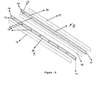
- the electrolysis cell (23), the top perspective view of its disassembled state is shown in Figure 5 , comprises two plate shaped electrodes (12) facing each other on the outermost section; an acidic water exit hole (13) and a basic water exit hole (14) in plate form and perforated structure which are positioned such that they correspond to the surfaces of the electrodes (12) facing each other, which are perforated separately at one end and which have a mid section separated with columns (74); a discharge channel (15) (shown in figure 7 ) which extends, on the corresponding surfaces, from the hole (29) to the acidic water exit hole (13) on one and from the hole (29) to the basic water exit hole (14) on the other, tie pieces (80) (shown in figure 7 ) which are formed, excluding the circumference of the discharge channel, around the acidic and basic water exit holes that have discharge channels (13, 14) (15) and which ensure that the channelled perforations (13, 14) are firmly tied to the unchanneled perforations (13, 14) by fixing the channelled per
- Cells (23) are placed such that the cartridges (8, 9) of the other cell and the separator ion film (10) are next to the outermost electrode (12).
- an electrode (12) functions as an anode for a cell present on one of its surface and functions as a cathode for a cell present on its other surface.
- the separator ion film (10) and the electrodes (12) are joined together such that they do not occlude the acidic and basic water exit holes (13, 14) located on the cartridges (8, 9).
- At least one electrolysis cell (23) is placed on the lower cap (1) such that it is parallel to the lateral sides (26') of the cap (1) and the diffuser (7) is fixed to the slot (21) perpendicularly to these (23).
- the depth of the basin (6) which is formed between the diffuser (7) and the cap side (26') is lower in comparison with the depth of the slot (21).
- the water delivered from the entry hole (3) accumulates in the basin (6). After the mains water passes to the device (A) through the entry hole (3), it is appropriately distributed to the electrolysis cells (23) by going through the diffuser (7).
- the electrical feed to the electrolysis cell (23), composed of two electrodes (12) located at the outermost, two cartridges (8, 9) placed between the electrodes (12) and a separator ion film (10) located at the mid most, is provided by a direct current source in desired voltages by means of the cables which are passed through the channels (22) below the lower cap (1) to at least one electrode (12) located at the outermost.
- the circumference of the acidic water exit hole (13) has tie piece structure. This tie piece structure (80) ensures that the two cartridges (8, 9) do not break apart from each other by fitting firmly on the acidic water exit hole (13) located on the other cartridge (9).
- the circumference of the basic water exit hole (14) has tie piece (80) structure and the said tie piece (80) ensures that the two cartridges do not break apart from each other by fitting firmly on the exit hole (14) of the acidic section cartridge (8).
- Columns (74) are formed along the cartridge in order to reinforce the cartridges (8, 9).
- the water delivered from the diffuser (7) is passed through the drain channels (17) which are formed on the last column in order to facilitate water passage along the cartridges (8, 9).
- the separator ion film (10) permits ion exchange and prevents acidic and basic water from mixing with each other between the acidic (8) and basic (9) cartridges.
- the water which is electrolyzed by giving an electrical current, passes from the electrode (12) to the cartridge (8, 9), from the cartridge (8, 9) to the separator ion film (10), from the separator ion film (10) to the cartridge (8, 9) and from here to the discharge channel (15) by guidance of the discharge channel (15) and from the discharge channel it reaches the exit holes (13, 14).
- the acidic and basic water obtained from each cell (23) is discharged by being accumulated inside the exit holes (13, 14).
- the electrolysis cell (23) is fed, for example, with 200 Volt DC, the voltage passes from one electrode (12) to the other by evenly decreasing manner in a 5 cell system comprised of 5 acidic (8) and 5 basic cartridges (9).
- a 5 cell system there are 6 electrodes and the voltage formed in these are, respectively, 200, 160, 120, 80, 40 and 0.
- the electrolysis device can be operated in desired voltages by changing the number of cells without having to use a transformer.
- the voltage per cell can be adjusted by changing number of cells without changing the current value.
- the desired performance is achieved.
- FIG 8 shows the flaps (24) which are formed in order to enable the electrolysis cell to be assembled to a washing machine.
- the assembly is completed by inserting bolts through the installation holes (25) that are located on the flaps (24) formed on the lower and upper caps (1, 2).
Landscapes
- Chemical & Material Sciences (AREA)
- Chemical Kinetics & Catalysis (AREA)
- Electrochemistry (AREA)
- General Chemical & Material Sciences (AREA)
- Life Sciences & Earth Sciences (AREA)
- Hydrology & Water Resources (AREA)
- Engineering & Computer Science (AREA)
- Environmental & Geological Engineering (AREA)
- Water Supply & Treatment (AREA)
- Organic Chemistry (AREA)
- Water Treatment By Electricity Or Magnetism (AREA)
- Electrolytic Production Of Non-Metals, Compounds, Apparatuses Therefor (AREA)
Claims (3)
- Elektrolysevorrichtung (A) zum Separieren von acidischem und basischem Wasser durch Elektrolyse von in Waschmaschinen genutztem Leitungswasser, umfassend eine untere Kappe (1),
eine obere Kappe (2),
Elektrolysezellen (23), jeweils umfassend- zwei plattenförmige einander gegenüberliegende Elektroden (12), die in dem äußersten Abschnitt angeordnet sind,- einen acidischen Einsatz (8) und einen basischen Einsatz (9), die zwischen den beiden Elektroden (12) angeordnet sind,- einen Separator (10), der zwischen den Einsätzen (8, 9) angeordnet ist und der ein Mischen von acidischen und basischen Komponenten zwischen dem acidischen und einem basischen Einsatz (8, 9) verhindert, während ein Ionenaustausch ermöglicht wird,- wobei der acidische sowie der basische Einsatz jeweils Öffnungen (29) besitzen, separiert durch Pfeiler (74), wobei jeder Einsatz eine Ausgangsöffnung (13) für acidisches Wasser und eine Ausgangsöffnung (14) für basisches Wasser an dem gegenüberliegenden Ende des Leitungswassereingangs besitzt,
wobei jeder acidische Einsatz (8) einen Ausgangsdurchlass (15) besitzt, der sich von einer Öffnung (29) zur Ausgangsöffnung (13) für acidisches Wasser auf der dem Separator gegenüberliegenden Flache besitzt, und jeder basische Einsatz (9) einen Auslassdurchlass (15) besitzt, der sich von einer Öffnung (29) zur Ausgangsöffnung (14) für basisches Wasser auf der Fläche der anderen Seite des Separators (10) erstreckt.- Verbindungsstücke (80), die an dem Umfang der Ausgangsöffnungen (13, 14) für acidisches und basisches Wasser angeordnet und mit jedem der Kanäle (15) verbunden sind, die an den entsprechenden Einsätzen (8, 9) vorliegen, und die in die entsprechenden Öffnungen (13,14) eingesetzt sind,einen Diffusor (7) mit einer Verbindungsplatte (71), die eine Anzahl von Spalten (71 a) entsprechend der Anzahl von Zellen (23) besitzt, um die Verteilung von Leitungswasser zu den Zellen (23) sicher zu stellen,
dadurch gekennzeichnet, dass
die obere Kappe (2) Seiten (26) besitzt, die einen Durchlass (28) in dem mittleren Abschnitt der inneren Fläche (27) der oberen Kappe (2) ausbilden,
die untere Kappe (1) Seiten (26'), die einen Durchlass (28') in dem mittleren Abschnitt der inneren Fläche (27') ausbilden, einen Schlitz (21) ausgebildet an einem Ende des Durchlasses (28'), sodass er auf den beiden gegenüberliegenden Seiten (26') um eine gewisse Länge in das Innere der Wandstärke eindringt, eine kantenartige Stufe (28), die sich entlang der Seite (26') angeordnet zwischen dem Schlitz (21) und der Seite des Durchlasses (26') erstreckt, eine Wassereingangsöffnung (3) angeordnet an der Seitenwand der Stufe (18), eine Ausgangsöffnung (4) für acidisches Wasser sowie eine Ausgangsöffnung (5) für basisches Wasser ausgebildet an den lateralen Seiten (26') des anderen Endes des Durchgangs (28), und ein Durchlass (22) belegt um einen elektrischen Anschluss mit der Elektrode zu verbinden, die unterhalb der inneren Fläche (27') von der Seite des Durchlasses (26') vertieft ist, besitzt, und dass die Elektrolysezellen (23) parallel zu den lateralen Seiten (26') der unteren Kappe (1) sind, und der Diffusor (7) zu diesen Zellen (23) senkrecht an dem Schlitz (21) befestigt ist,
und dass die Elektrolysezellen (23) derart angeordnet sind, dass die Flächen einer Elektrode (12) als Anode für die dieser Fläche gegenüberliegende Zelle dienen und als Kathode für die der anderen Fläche gegenüberliegende Zelle dienen. - Elektrolysevorrichtung (A) nach Anspruch 1, dadurch gekennzeichnet, dass jeder Einsatz (8, 9) Drainagedurchlässe (17) umfasst, die an der Innenfläche des letzten Feilers (74) angeordnet sind.
- Elektrolysevorrichtung (A) nach Anspruch 1, dadurch gekennzeichnet, dass der Diffusor (7) eine Siebplatte(73) mit zahlreichen Öffnungen vor und/oder hinter der Verteilerplatte (71) umfasst.
Applications Claiming Priority (1)
| Application Number | Priority Date | Filing Date | Title |
|---|---|---|---|
| TR2009/00349A TR200900349A2 (tr) | 2009-01-16 | 2009-01-16 | Elektroliz aparatı |
Publications (3)
| Publication Number | Publication Date |
|---|---|
| EP2213625A2 EP2213625A2 (de) | 2010-08-04 |
| EP2213625A3 EP2213625A3 (de) | 2010-08-11 |
| EP2213625B1 true EP2213625B1 (de) | 2013-11-13 |
Family
ID=42101573
Family Applications (1)
| Application Number | Title | Priority Date | Filing Date |
|---|---|---|---|
| EP10150248.2A Not-in-force EP2213625B1 (de) | 2009-01-16 | 2010-01-07 | Elektrolysevorrichtung |
Country Status (2)
| Country | Link |
|---|---|
| EP (1) | EP2213625B1 (de) |
| TR (1) | TR200900349A2 (de) |
Families Citing this family (1)
| Publication number | Priority date | Publication date | Assignee | Title |
|---|---|---|---|---|
| CN105862326A (zh) * | 2016-05-13 | 2016-08-17 | 鲍传奎 | 一种洗衣方法和投入式洗衣装置 |
Family Cites Families (8)
| Publication number | Priority date | Publication date | Assignee | Title |
|---|---|---|---|---|
| JPH0731975A (ja) * | 1991-05-02 | 1995-02-03 | Shinichi Natsume | イオン水生成器 |
| JP2786408B2 (ja) * | 1995-06-06 | 1998-08-13 | 壽化工機株式会社 | 電解酸性水製造装置 |
| JPH10314740A (ja) | 1997-05-19 | 1998-12-02 | Permelec Electrode Ltd | 酸性水製造用電解槽 |
| JP2002079248A (ja) | 2000-09-06 | 2002-03-19 | Tominaga Oil Pump Mfg Co Ltd | 電解水生成装置 |
| JP3846201B2 (ja) * | 2001-01-31 | 2006-11-15 | 松下電工株式会社 | 電解槽 |
| WO2004065682A1 (en) | 2003-01-22 | 2004-08-05 | Hee Jung Kim | Washing machine having electrolysis apparatus |
| JP3581362B1 (ja) * | 2003-03-18 | 2004-10-27 | 中国電機製造株式会社 | アルカリイオン整水器 |
| US20090017174A1 (en) * | 2004-08-27 | 2009-01-15 | University Of Georgia Research Foundation, Inc. | Food product treatment using alkaline electrolyzed water |
-
2009
- 2009-01-16 TR TR2009/00349A patent/TR200900349A2/xx unknown
-
2010
- 2010-01-07 EP EP10150248.2A patent/EP2213625B1/de not_active Not-in-force
Also Published As
| Publication number | Publication date |
|---|---|
| TR200900349A2 (tr) | 2010-08-23 |
| EP2213625A2 (de) | 2010-08-04 |
| EP2213625A3 (de) | 2010-08-11 |
Similar Documents
| Publication | Publication Date | Title |
|---|---|---|
| US6395154B1 (en) | Electrochemical cell using a folded double electrode plate | |
| US10301200B2 (en) | Flow distributors for electrochemical separation | |
| US20020088710A1 (en) | Method and apparatus for electrocoagulation of liquids | |
| TWI654144B (zh) | 臭氧水製造裝置 | |
| US20230295815A1 (en) | Combined Current Carrier Circulation Chamber and Frame for use in Unipolar Electrochemical Devices | |
| US8444833B2 (en) | Device for electrochemical water preparation | |
| KR101191480B1 (ko) | 세퍼레이터를 포함한 무격막 전해조 및 이를 포함하는 전해수 시스템 | |
| US11131030B2 (en) | Electrolysis cell or electrode plate with a gas diffusion electrode | |
| EP2213625B1 (de) | Elektrolysevorrichtung | |
| US6846393B2 (en) | Electrolysis cells | |
| US5637204A (en) | End casing for an electrodialyzer electrodialyzer equipped with such a casing and use of the said electrodialyzer | |
| KR20180083717A (ko) | 역전기투석 장치를 이용한 저 에너지 소비형 수산화나트륨 생산 장치 및 이를 이용한 하이브리드 시스템 | |
| US9908794B2 (en) | Electrocoagulation chamber with atmospheric and pressurized flow regimes | |
| KR101215602B1 (ko) | 유통식 전해장치 및 이를 이용하는 분사장치 | |
| EP2115445A1 (de) | Interne flusssteuerung in elektrolytischen zellen | |
| KR101782356B1 (ko) | 수처리용 전극 모듈 및 이를 채용하는 수처리 시스템 | |
| WO2016114364A1 (ja) | 電解水生成装置 | |
| KR200365102Y1 (ko) | 이온수 유로 모듈전극판 구조 | |
| CA2276444A1 (en) | Electrochemical cells and electrochemical systems | |
| CN221544294U (zh) | 电催化装置及废水处理设备 | |
| KR200203167Y1 (ko) | 재생에너지의 효율적 활용을 위한 분리형 물의전기분해장치 및 이를 이용한 연소장치 | |
| KR101341036B1 (ko) | 이온수기의 전해조용 전극판 및 이를 포함하는 격막 구조 | |
| AU756321B2 (en) | Improvements in electrolysis cells | |
| KR20070088411A (ko) | 개선된 이온수 생성 장치 | |
| JP2006307248A (ja) | 水素製造装置 |
Legal Events
| Date | Code | Title | Description |
|---|---|---|---|
| PUAI | Public reference made under article 153(3) epc to a published international application that has entered the european phase |
Free format text: ORIGINAL CODE: 0009012 |
|
| PUAL | Search report despatched |
Free format text: ORIGINAL CODE: 0009013 |
|
| AK | Designated contracting states |
Kind code of ref document: A2 Designated state(s): AT BE BG CH CY CZ DE DK EE ES FI FR GB GR HR HU IE IS IT LI LT LU LV MC MK MT NL NO PL PT RO SE SI SK SM TR |
|
| AX | Request for extension of the european patent |
Extension state: AL BA RS |
|
| AK | Designated contracting states |
Kind code of ref document: A3 Designated state(s): AT BE BG CH CY CZ DE DK EE ES FI FR GB GR HR HU IE IS IT LI LT LU LV MC MK MT NL NO PL PT RO SE SI SK SM TR |
|
| AX | Request for extension of the european patent |
Extension state: AL BA RS |
|
| 17P | Request for examination filed |
Effective date: 20110114 |
|
| 17Q | First examination report despatched |
Effective date: 20120427 |
|
| GRAJ | Information related to disapproval of communication of intention to grant by the applicant or resumption of examination proceedings by the epo deleted |
Free format text: ORIGINAL CODE: EPIDOSDIGR1 |
|
| GRAP | Despatch of communication of intention to grant a patent |
Free format text: ORIGINAL CODE: EPIDOSNIGR1 |
|
| GRAP | Despatch of communication of intention to grant a patent |
Free format text: ORIGINAL CODE: EPIDOSNIGR1 |
|
| INTG | Intention to grant announced |
Effective date: 20130603 |
|
| GRAS | Grant fee paid |
Free format text: ORIGINAL CODE: EPIDOSNIGR3 |
|
| GRAA | (expected) grant |
Free format text: ORIGINAL CODE: 0009210 |
|
| AK | Designated contracting states |
Kind code of ref document: B1 Designated state(s): AT BE BG CH CY CZ DE DK EE ES FI FR GB GR HR HU IE IS IT LI LT LU LV MC MK MT NL NO PL PT RO SE SI SK SM TR |
|
| REG | Reference to a national code |
Ref country code: GB Ref legal event code: FG4D |
|
| REG | Reference to a national code |
Ref country code: CH Ref legal event code: EP |
|
| REG | Reference to a national code |
Ref country code: AT Ref legal event code: REF Ref document number: 640512 Country of ref document: AT Kind code of ref document: T Effective date: 20131215 |
|
| REG | Reference to a national code |
Ref country code: IE Ref legal event code: FG4D |
|
| REG | Reference to a national code |
Ref country code: DE Ref legal event code: R096 Ref document number: 602010011672 Country of ref document: DE Effective date: 20140109 |
|
| REG | Reference to a national code |
Ref country code: NL Ref legal event code: VDEP Effective date: 20131113 |
|
| REG | Reference to a national code |
Ref country code: AT Ref legal event code: MK05 Ref document number: 640512 Country of ref document: AT Kind code of ref document: T Effective date: 20131113 |
|
| REG | Reference to a national code |
Ref country code: LT Ref legal event code: MG4D |
|
| PG25 | Lapsed in a contracting state [announced via postgrant information from national office to epo] |
Ref country code: SE Free format text: LAPSE BECAUSE OF FAILURE TO SUBMIT A TRANSLATION OF THE DESCRIPTION OR TO PAY THE FEE WITHIN THE PRESCRIBED TIME-LIMIT Effective date: 20131113 Ref country code: LT Free format text: LAPSE BECAUSE OF FAILURE TO SUBMIT A TRANSLATION OF THE DESCRIPTION OR TO PAY THE FEE WITHIN THE PRESCRIBED TIME-LIMIT Effective date: 20131113 Ref country code: NO Free format text: LAPSE BECAUSE OF FAILURE TO SUBMIT A TRANSLATION OF THE DESCRIPTION OR TO PAY THE FEE WITHIN THE PRESCRIBED TIME-LIMIT Effective date: 20140213 Ref country code: IS Free format text: LAPSE BECAUSE OF FAILURE TO SUBMIT A TRANSLATION OF THE DESCRIPTION OR TO PAY THE FEE WITHIN THE PRESCRIBED TIME-LIMIT Effective date: 20140313 Ref country code: NL Free format text: LAPSE BECAUSE OF FAILURE TO SUBMIT A TRANSLATION OF THE DESCRIPTION OR TO PAY THE FEE WITHIN THE PRESCRIBED TIME-LIMIT Effective date: 20131113 Ref country code: HR Free format text: LAPSE BECAUSE OF FAILURE TO SUBMIT A TRANSLATION OF THE DESCRIPTION OR TO PAY THE FEE WITHIN THE PRESCRIBED TIME-LIMIT Effective date: 20131113 Ref country code: FI Free format text: LAPSE BECAUSE OF FAILURE TO SUBMIT A TRANSLATION OF THE DESCRIPTION OR TO PAY THE FEE WITHIN THE PRESCRIBED TIME-LIMIT Effective date: 20131113 |
|
| PG25 | Lapsed in a contracting state [announced via postgrant information from national office to epo] |
Ref country code: LV Free format text: LAPSE BECAUSE OF FAILURE TO SUBMIT A TRANSLATION OF THE DESCRIPTION OR TO PAY THE FEE WITHIN THE PRESCRIBED TIME-LIMIT Effective date: 20131113 Ref country code: ES Free format text: LAPSE BECAUSE OF FAILURE TO SUBMIT A TRANSLATION OF THE DESCRIPTION OR TO PAY THE FEE WITHIN THE PRESCRIBED TIME-LIMIT Effective date: 20131113 Ref country code: CY Free format text: LAPSE BECAUSE OF FAILURE TO SUBMIT A TRANSLATION OF THE DESCRIPTION OR TO PAY THE FEE WITHIN THE PRESCRIBED TIME-LIMIT Effective date: 20131113 Ref country code: AT Free format text: LAPSE BECAUSE OF FAILURE TO SUBMIT A TRANSLATION OF THE DESCRIPTION OR TO PAY THE FEE WITHIN THE PRESCRIBED TIME-LIMIT Effective date: 20131113 Ref country code: BE Free format text: LAPSE BECAUSE OF FAILURE TO SUBMIT A TRANSLATION OF THE DESCRIPTION OR TO PAY THE FEE WITHIN THE PRESCRIBED TIME-LIMIT Effective date: 20131113 |
|
| PG25 | Lapsed in a contracting state [announced via postgrant information from national office to epo] |
Ref country code: PT Free format text: LAPSE BECAUSE OF FAILURE TO SUBMIT A TRANSLATION OF THE DESCRIPTION OR TO PAY THE FEE WITHIN THE PRESCRIBED TIME-LIMIT Effective date: 20140313 |
|
| PG25 | Lapsed in a contracting state [announced via postgrant information from national office to epo] |
Ref country code: EE Free format text: LAPSE BECAUSE OF FAILURE TO SUBMIT A TRANSLATION OF THE DESCRIPTION OR TO PAY THE FEE WITHIN THE PRESCRIBED TIME-LIMIT Effective date: 20131113 |
|
| REG | Reference to a national code |
Ref country code: DE Ref legal event code: R097 Ref document number: 602010011672 Country of ref document: DE |
|
| PG25 | Lapsed in a contracting state [announced via postgrant information from national office to epo] |
Ref country code: RO Free format text: LAPSE BECAUSE OF FAILURE TO SUBMIT A TRANSLATION OF THE DESCRIPTION OR TO PAY THE FEE WITHIN THE PRESCRIBED TIME-LIMIT Effective date: 20131113 Ref country code: SK Free format text: LAPSE BECAUSE OF FAILURE TO SUBMIT A TRANSLATION OF THE DESCRIPTION OR TO PAY THE FEE WITHIN THE PRESCRIBED TIME-LIMIT Effective date: 20131113 Ref country code: CZ Free format text: LAPSE BECAUSE OF FAILURE TO SUBMIT A TRANSLATION OF THE DESCRIPTION OR TO PAY THE FEE WITHIN THE PRESCRIBED TIME-LIMIT Effective date: 20131113 Ref country code: MC Free format text: LAPSE BECAUSE OF FAILURE TO SUBMIT A TRANSLATION OF THE DESCRIPTION OR TO PAY THE FEE WITHIN THE PRESCRIBED TIME-LIMIT Effective date: 20131113 Ref country code: PL Free format text: LAPSE BECAUSE OF FAILURE TO SUBMIT A TRANSLATION OF THE DESCRIPTION OR TO PAY THE FEE WITHIN THE PRESCRIBED TIME-LIMIT Effective date: 20131113 Ref country code: LU Free format text: LAPSE BECAUSE OF FAILURE TO SUBMIT A TRANSLATION OF THE DESCRIPTION OR TO PAY THE FEE WITHIN THE PRESCRIBED TIME-LIMIT Effective date: 20140107 |
|
| REG | Reference to a national code |
Ref country code: CH Ref legal event code: PL |
|
| PLBE | No opposition filed within time limit |
Free format text: ORIGINAL CODE: 0009261 |
|
| STAA | Information on the status of an ep patent application or granted ep patent |
Free format text: STATUS: NO OPPOSITION FILED WITHIN TIME LIMIT |
|
| PG25 | Lapsed in a contracting state [announced via postgrant information from national office to epo] |
Ref country code: DK Free format text: LAPSE BECAUSE OF FAILURE TO SUBMIT A TRANSLATION OF THE DESCRIPTION OR TO PAY THE FEE WITHIN THE PRESCRIBED TIME-LIMIT Effective date: 20131113 |
|
| 26N | No opposition filed |
Effective date: 20140814 |
|
| GBPC | Gb: european patent ceased through non-payment of renewal fee |
Effective date: 20140213 |
|
| PG25 | Lapsed in a contracting state [announced via postgrant information from national office to epo] |
Ref country code: CH Free format text: LAPSE BECAUSE OF NON-PAYMENT OF DUE FEES Effective date: 20140131 Ref country code: LI Free format text: LAPSE BECAUSE OF NON-PAYMENT OF DUE FEES Effective date: 20140131 |
|
| REG | Reference to a national code |
Ref country code: FR Ref legal event code: ST Effective date: 20140930 |
|
| REG | Reference to a national code |
Ref country code: IE Ref legal event code: MM4A |
|
| REG | Reference to a national code |
Ref country code: DE Ref legal event code: R097 Ref document number: 602010011672 Country of ref document: DE Effective date: 20140814 |
|
| PG25 | Lapsed in a contracting state [announced via postgrant information from national office to epo] |
Ref country code: FR Free format text: LAPSE BECAUSE OF NON-PAYMENT OF DUE FEES Effective date: 20140131 |
|
| PG25 | Lapsed in a contracting state [announced via postgrant information from national office to epo] |
Ref country code: GB Free format text: LAPSE BECAUSE OF NON-PAYMENT OF DUE FEES Effective date: 20140213 Ref country code: IE Free format text: LAPSE BECAUSE OF NON-PAYMENT OF DUE FEES Effective date: 20140107 |
|
| PG25 | Lapsed in a contracting state [announced via postgrant information from national office to epo] |
Ref country code: SI Free format text: LAPSE BECAUSE OF FAILURE TO SUBMIT A TRANSLATION OF THE DESCRIPTION OR TO PAY THE FEE WITHIN THE PRESCRIBED TIME-LIMIT Effective date: 20131113 |
|
| PG25 | Lapsed in a contracting state [announced via postgrant information from national office to epo] |
Ref country code: MT Free format text: LAPSE BECAUSE OF FAILURE TO SUBMIT A TRANSLATION OF THE DESCRIPTION OR TO PAY THE FEE WITHIN THE PRESCRIBED TIME-LIMIT Effective date: 20131113 |
|
| PG25 | Lapsed in a contracting state [announced via postgrant information from national office to epo] |
Ref country code: SM Free format text: LAPSE BECAUSE OF FAILURE TO SUBMIT A TRANSLATION OF THE DESCRIPTION OR TO PAY THE FEE WITHIN THE PRESCRIBED TIME-LIMIT Effective date: 20131113 |
|
| PG25 | Lapsed in a contracting state [announced via postgrant information from national office to epo] |
Ref country code: GR Free format text: LAPSE BECAUSE OF FAILURE TO SUBMIT A TRANSLATION OF THE DESCRIPTION OR TO PAY THE FEE WITHIN THE PRESCRIBED TIME-LIMIT Effective date: 20140214 Ref country code: IT Free format text: LAPSE BECAUSE OF FAILURE TO SUBMIT A TRANSLATION OF THE DESCRIPTION OR TO PAY THE FEE WITHIN THE PRESCRIBED TIME-LIMIT Effective date: 20131113 Ref country code: BG Free format text: LAPSE BECAUSE OF FAILURE TO SUBMIT A TRANSLATION OF THE DESCRIPTION OR TO PAY THE FEE WITHIN THE PRESCRIBED TIME-LIMIT Effective date: 20131113 |
|
| PG25 | Lapsed in a contracting state [announced via postgrant information from national office to epo] |
Ref country code: HU Free format text: LAPSE BECAUSE OF FAILURE TO SUBMIT A TRANSLATION OF THE DESCRIPTION OR TO PAY THE FEE WITHIN THE PRESCRIBED TIME-LIMIT; INVALID AB INITIO Effective date: 20100107 |
|
| REG | Reference to a national code |
Ref country code: DE Ref legal event code: R084 Ref document number: 602010011672 Country of ref document: DE |
|
| PG25 | Lapsed in a contracting state [announced via postgrant information from national office to epo] |
Ref country code: MK Free format text: LAPSE BECAUSE OF FAILURE TO SUBMIT A TRANSLATION OF THE DESCRIPTION OR TO PAY THE FEE WITHIN THE PRESCRIBED TIME-LIMIT Effective date: 20131113 |
|
| PGFP | Annual fee paid to national office [announced via postgrant information from national office to epo] |
Ref country code: DE Payment date: 20200121 Year of fee payment: 11 |
|
| PGFP | Annual fee paid to national office [announced via postgrant information from national office to epo] |
Ref country code: TR Payment date: 20200103 Year of fee payment: 11 |
|
| REG | Reference to a national code |
Ref country code: DE Ref legal event code: R119 Ref document number: 602010011672 Country of ref document: DE |
|
| PG25 | Lapsed in a contracting state [announced via postgrant information from national office to epo] |
Ref country code: DE Free format text: LAPSE BECAUSE OF NON-PAYMENT OF DUE FEES Effective date: 20210803 |
|
| PG25 | Lapsed in a contracting state [announced via postgrant information from national office to epo] |
Ref country code: TR Free format text: LAPSE BECAUSE OF NON-PAYMENT OF DUE FEES Effective date: 20210107 |