EP2213425A1 - Vertical multi-joint robot - Google Patents
Vertical multi-joint robot Download PDFInfo
- Publication number
- EP2213425A1 EP2213425A1 EP08853361A EP08853361A EP2213425A1 EP 2213425 A1 EP2213425 A1 EP 2213425A1 EP 08853361 A EP08853361 A EP 08853361A EP 08853361 A EP08853361 A EP 08853361A EP 2213425 A1 EP2213425 A1 EP 2213425A1
- Authority
- EP
- European Patent Office
- Prior art keywords
- upper arm
- rotation axis
- arm
- motor
- robot
- Prior art date
- Legal status (The legal status is an assumption and is not a legal conclusion. Google has not performed a legal analysis and makes no representation as to the accuracy of the status listed.)
- Granted
Links
Images





Classifications
-
- B—PERFORMING OPERATIONS; TRANSPORTING
- B25—HAND TOOLS; PORTABLE POWER-DRIVEN TOOLS; MANIPULATORS
- B25J—MANIPULATORS; CHAMBERS PROVIDED WITH MANIPULATION DEVICES
- B25J9/00—Program-controlled manipulators
- B25J9/06—Program-controlled manipulators characterised by multi-articulated arms
-
- B—PERFORMING OPERATIONS; TRANSPORTING
- B25—HAND TOOLS; PORTABLE POWER-DRIVEN TOOLS; MANIPULATORS
- B25J—MANIPULATORS; CHAMBERS PROVIDED WITH MANIPULATION DEVICES
- B25J19/00—Accessories fitted to manipulators, e.g. for monitoring, for viewing; Safety devices combined with or specially adapted for use in connection with manipulators
- B25J19/0025—Means for supplying energy to the end effector
- B25J19/0029—Means for supplying energy to the end effector arranged within the different robot elements
-
- B—PERFORMING OPERATIONS; TRANSPORTING
- B25—HAND TOOLS; PORTABLE POWER-DRIVEN TOOLS; MANIPULATORS
- B25J—MANIPULATORS; CHAMBERS PROVIDED WITH MANIPULATION DEVICES
- B25J9/00—Program-controlled manipulators
- B25J9/02—Program-controlled manipulators characterised by movement of the arms, e.g. cartesian coordinate type
- B25J9/04—Program-controlled manipulators characterised by movement of the arms, e.g. cartesian coordinate type by rotating at least one arm, excluding the head movement itself, e.g. cylindrical coordinate type or polar coordinate type
- B25J9/046—Revolute coordinate type
-
- Y—GENERAL TAGGING OF NEW TECHNOLOGICAL DEVELOPMENTS; GENERAL TAGGING OF CROSS-SECTIONAL TECHNOLOGIES SPANNING OVER SEVERAL SECTIONS OF THE IPC; TECHNICAL SUBJECTS COVERED BY FORMER USPC CROSS-REFERENCE ART COLLECTIONS [XRACs] AND DIGESTS
- Y10—TECHNICAL SUBJECTS COVERED BY FORMER USPC
- Y10T—TECHNICAL SUBJECTS COVERED BY FORMER US CLASSIFICATION
- Y10T74/00—Machine element or mechanism
- Y10T74/20—Control lever and linkage systems
- Y10T74/20207—Multiple controlling elements for single controlled element
- Y10T74/20305—Robotic arm
-
- Y—GENERAL TAGGING OF NEW TECHNOLOGICAL DEVELOPMENTS; GENERAL TAGGING OF CROSS-SECTIONAL TECHNOLOGIES SPANNING OVER SEVERAL SECTIONS OF THE IPC; TECHNICAL SUBJECTS COVERED BY FORMER USPC CROSS-REFERENCE ART COLLECTIONS [XRACs] AND DIGESTS
- Y10—TECHNICAL SUBJECTS COVERED BY FORMER USPC
- Y10T—TECHNICAL SUBJECTS COVERED BY FORMER US CLASSIFICATION
- Y10T74/00—Machine element or mechanism
- Y10T74/20—Control lever and linkage systems
- Y10T74/20207—Multiple controlling elements for single controlled element
- Y10T74/20305—Robotic arm
- Y10T74/20311—Robotic arm including power cable or connector
-
- Y—GENERAL TAGGING OF NEW TECHNOLOGICAL DEVELOPMENTS; GENERAL TAGGING OF CROSS-SECTIONAL TECHNOLOGIES SPANNING OVER SEVERAL SECTIONS OF THE IPC; TECHNICAL SUBJECTS COVERED BY FORMER USPC CROSS-REFERENCE ART COLLECTIONS [XRACs] AND DIGESTS
- Y10—TECHNICAL SUBJECTS COVERED BY FORMER USPC
- Y10T—TECHNICAL SUBJECTS COVERED BY FORMER US CLASSIFICATION
- Y10T74/00—Machine element or mechanism
- Y10T74/20—Control lever and linkage systems
- Y10T74/20207—Multiple controlling elements for single controlled element
- Y10T74/20305—Robotic arm
- Y10T74/20317—Robotic arm including electric motor
-
- Y—GENERAL TAGGING OF NEW TECHNOLOGICAL DEVELOPMENTS; GENERAL TAGGING OF CROSS-SECTIONAL TECHNOLOGIES SPANNING OVER SEVERAL SECTIONS OF THE IPC; TECHNICAL SUBJECTS COVERED BY FORMER USPC CROSS-REFERENCE ART COLLECTIONS [XRACs] AND DIGESTS
- Y10—TECHNICAL SUBJECTS COVERED BY FORMER USPC
- Y10T—TECHNICAL SUBJECTS COVERED BY FORMER US CLASSIFICATION
- Y10T74/00—Machine element or mechanism
- Y10T74/20—Control lever and linkage systems
- Y10T74/20207—Multiple controlling elements for single controlled element
- Y10T74/20305—Robotic arm
- Y10T74/20329—Joint between elements
Definitions
- the present invention relates to a vertical articulated robot having a redundant axis.
- Recent industrial robots are required to perform processes of welding, applying sealing agents, assembling parts, etc., by inserting a wrist assembly, which holds an operating tool, and a part of an arm supporting the wrist assembly into, for example, an automobile body. Therefore, there have been demands for robots that have smaller wrist portions and arms with smaller diameters and that are capable of performing high-speed, high-precision operations.
- a plane including an upper arm and a front arm is always in a vertical orientation, and there is a risk that the arms will interfere with an obstacle or the like placed on an approach route thereof, depending on an area into which the arms are to be inserted in the operation.
- the industrial robots are and have been required to complete the processes of welding, applying sealing agents, assembling parts, etc., in a shorter time to increase the process throughput and comply with the increase in the numbers of products to be produced and production steps.
- the requirement regarding the throughput is not only to complete each production step in a short time but also to allow maintenance of the robot, which is operated around the clock, to be completed in a short time. To improve the productivity, it is important to increase the operating time of the robot and complete each production step in a short time.
- the robots are collectively arranged to reduce the space for the manufacturing processes.
- a conventional industrial robot that does not have a redundant axis cannot bring a tool provided at a wrist axis of the robot to a position near the robot itself. Therefore, even when multiple robots are collectively arranged, the robots cannot perform processes in areas near themselves and operating areas cannot be increased.
- robots having redundant axes have been developed. Additionally, there has been a demand for a robot capable of performing an operation in an area close to the robot itself in consideration of an arm length.
- the industrial robots capable of moving flexibly are required to perform complex movements in an environment where the robots are densely arranged, and accordingly the industrial robots have complex structures.
- This vertical articulated robot includes a base; a turning base provided on the base so as to be pivotable about a first rotation axis; a first upper arm provided on the turning base so as to be turnable about a second rotation axis that is in a plane perpendicular to the first rotation axis; a second upper arm provided on a distal end portion of the first upper arm so as to be pivotable about a third rotation axis that is perpendicular to the second rotation axis; a front arm provided on a distal end portion of the second upper arm so as to be turnable about a fourth rotation axis that is in a plane perpendicular to the third rotation axis; a wrist assembly mounted on a distal end portion of the front arm; and motors that rotate the first upper arm, the second upper arm, and the front arm about the respective rotation axes.
- the seven-degree-of-freedom vertical articulated robot according to the related art is capable of avoiding interference with a workpiece or peripheral devices and interference between the arms,
- the drive motor for turning the second upper arm is disposed in the second upper arm 103.
- an inner stator and an outer rotor of the drive motor for the second upper arm are fixed to the first upper arm and the second upper arm, respectively.
- the second upper arm is turned about the third rotation axis that is perpendicular to the second rotation axis. Therefore, the drive motor cannot be replaced unless the second upper arm is separated from the robot, and there is a problem that it takes a long time to replace the drive motor. Even if it is not necessary to replace the drive motor, it is necessary to regularly apply grease to a reduction gears. Also in this case, it is necessary to separate the second upper arm from the robot.
- an object of the present invention is to provide a vertical articulated robot in which a drive motor or a cable can be replaced in a short time, which can readily correct mechanical displacements, and which can perform an operation in an area near the robot.
- a vertical articulated robot includes a base; a turning base provided on the base so as to be pivotable about a first rotation axis; a first upper arm provided on the turning base so as to be turnable about a second rotation axis that is in a plane perpendicular to the first rotation axis; a second upper arm provided on a distal end portion of the first upper arm so as to be pivotable about a third rotation axis that is perpendicular to the second rotation axis; a front arm provided on a distal end portion of the second upper arm so as to be turnable about a fourth rotation axis that is in a plane perpendicular to the third rotation axis; a wrist assembly mounted on a distal end portion of the front arm; and motors that rotate the first upper arm, the second upper arm, the front arm, and the wrist assembly about the respective rotation axes.
- the motor that rotates the second upper arm is mounted on a frame of the second upper arm.
- the motor that rotates the second upper arm in the state in which the first upper arm is in a vertical orientation, is mounted on the frame of the second upper arm such that a rotating shaft of the motor extends perpendicular to a ground surface and such that an output shaft of the motor faces toward the ground surface.
- the motor that rotates the second upper arm in the state in which the first upper arm is in a vertical orientation, the motor that rotates the second upper arm is mounted on a rear surface of the frame of the second upper arm such that a rotating shaft of the motor extends parallel to a ground surface.
- the distal end portion of the first upper arm is provided with a reduction gears that rotates the second upper arm and is formed in an inverted L-shape.
- the second upper arm is provided with the motor that rotates the second upper arm and is formed in an L-shape.
- a length of the first upper arm is determined on the basis of a distance to the operating area.
- the length of the first upper arm is determined such that a process of replacing a motor unit can be performed without causing an interference between the motor unit and an upper end portion of the first upper arm.
- a length of the second upper arm is determined on the basis of a distance to the operating area.
- the length of the second upper arm is determined such that a process of replacing a motor unit can be performed without causing an interference between the motor unit and the motor that drives the front arm.
- the motor that rotates the second upper arm in the state in which the first upper arm is in a vertical orientation, is mounted on the frame of the second upper arm such that a rotating shaft of the motor extends perpendicular to a ground surface and such that an output shaft of the motor faces toward the ground surface.
- the output shaft of the motor is provided with an input gear that meshes with the reduction gears provided on the first upper arm.
- the motor that rotates the second upper arm is, the motor that rotates the second upper arm is mounted on a rear surface of the frame of the second upper arm such that a rotating shaft of the motor extends parallel to a ground surface.
- a vertical articulated robot includes a base; a turning base provided on the base so as to be pivotable about a first rotation axis; a first upper arm provided on the turning base so as to be turnable about a second rotation axis that is in a plane perpendicular to the first rotation axis; a second upper arm provided on a distal end portion of the first upper arm so as to be pivotable about a third rotation axis that is perpendicular to the second rotation axis; a front arm provided on a distal end portion of the second upper arm so as to be turnable about a fourth rotation axis that is in a plane perpendicular to the third rotation axis; a wrist assembly mounted on a distal end portion of the front arm; and motors that rotate the first upper arm, the second upper arm, the front arm, and the wrist assembly about the respective rotation axes
- a wire body that extends from the turning base is arranged so as to extend along a side surface of the first upper arm, is fixed to the side surface of the first upper arm at a central section of the first upper arm, is bent horizontally onto a rear surface of the first upper arm, and is fixed to the rear surface of the first upper arm at an upper end position of the first upper arm.
- the wire body is bent vertically in a U-shape so as to extend along a side surface of the second upper arm, is fixed to the second upper arm at a lower end position of the second upper arm, is bent horizontally so as to extend along another side surface of the second upper arm, is bent vertically at the center of the another side surface of the second upper arm, is fixed to the second upper arm at a central section of the second upper arm, is fixed to the front arm at a lower end position of the front arm, and extends into the front arm.
- the robot since the robot has a redundant axis, processes of welding, applying sealing agents, assembling parts, etc., can be performed without causing an interference with an obstacle. Therefore, the versatility of the manufacturing line can be increased.
- the motor that drives the second upper arm is mounted on the frame of the second upper arm, the motor is exposed to the outside. Therefore, the motor can be readily replaced with another motor and the time required for the replacing process can be reduced.
- the motor replacing process can be performed simply by removing the motor, it is not necessary to remove the arms. Therefore, no mechanical displacements occur between the arms, and it is not necessary to teach trajectories to the robot again when the robot is operated after the motor replacing process.
- a minimum length of the first upper arm or the second upper arm is determined as a length at which a drive motor and a motor unit arranged on the first upper arm or the second upper arm can be prevented from interfering with another component. Therefore, the tool attached at the wrist axis of the robot can be brought close to the robot itself.
- a transmission line connected to the drive motors or the operating tool provided at the wrist axis is arranged such that the transmission line does not protrude outward from the robot irrespective of the operational state. Therefore, the size of the robot can be set to a minimum size and maintenance of wiring lines can be facilitated at the same time.
- Fig. 1 shows a seven-degree-of-freedom vertical articulated robot according to an embodiment of the present invention, where (a) is a side view and (b) is a front view of the robot.
- a rotation axis (1) is perpendicular to the ground surface.
- a turning base 2 is provided with a turning drive motor 4 attached thereto, and an output shaft 4-1 of the turning drive motor 4 is connected to an input shaft of a reduction gears 3.
- the reduction gears 3 is a turning reduction gears and is supported by a robot base 1 and the turning base 2 such that the base 1 and the turning base 2 are relatively pivotable.
- the turning base 2 and the reduction gears 3 are arranged on the rotation axis (1).
- a drive motor 7 for a first upper arm 5 is arranged on a second rotation axis (2) in an opening provided in the above-described turning base 2.
- the second rotation axis (2) is in a plane perpendicular to the rotation axis (1).
- An output shaft 7-1 of the drive motor 7 for the first upper arm 5 is connected to an input shaft of a reduction gears 6 for the first upper arm 5.
- the reduction gears 6 for the first upper arm is secured to both the opening in the turning base 2 and a side surface of the first upper arm 5, and is supported so as to be turnable about the second rotation axis (2).
- the first upper arm 5 has an inverted L shape such that an L-shaped member is vertically inverted.
- An upper end portion of the first upper arm 5 supports a second upper arm 8 with a reduction gears 9 interposed therebetween.
- the reduction gears 9 is arranged on a third rotation axis (3) that is perpendicular to the second rotation axis (2) and that is on the same plate as the first rotation axis (1).
- the second upper arm 8 is supported so as to be turnable about the third rotation axis (3).
- the drive motor 7 for the first upper arm 5 can be arranged such that the drive motor 7 does not protrude from the robot in the width direction thereof when viewed from the front.
- the length of the first upper arm 5 is determined on the basis of the distance to the operating area.
- the length of the first upper arm 5 is determined such that a motor unit 7A can be replaced without causing an interference between the motor unit 7A and the upper end portion of the first upper arm 5.
- the second upper arm 8 has an L-shape that is symmetric to the shape of the first upper arm 5, so that a drive motor 10 for the second upper arm can be attached to the second upper arm 8 on the third rotation axis (3).
- the drive motor 10 for turning the second upper arm 8 is attached to the second upper arm 8.
- the drive motor 10 for the second upper arm 8 can be arranged such that the drive motor 10 does not protrude from robot in the width direction thereof when viewed from the front.
- An output shaft 10-1 of the drive motor 10 for turning the second upper arm 8 is connected to an input shaft of the reduction gears 9 for the first upper arm 8.
- the reduction gears 9 for the second upper arm 8 is secured to both the upper end portion of the first upper arm 5 and the bottom surface of the second upper arm 8, and is supported so as to be pivotable.
- a fourth rotation center (4) is perpendicular to and is on the same plane as the third rotation axis (3).
- a drive motor 13 and a reduction gears 12 for a front arm 11 are arranged on the fourth rotation axis.
- An output shaft 13-1 of the drive motor 13 for the front arm 11 is connected to an input shaft of the reduction gears 12 for the front arm 11.
- the reduction gears 12 for the front arm 11 is secured to both an opening in the front arm 11 and a side surface of the second upper arm 8, and is rotatably supported.
- a rotation axis (5) is in a plane that is perpendicular to the rotation axis (4) and on which the third rotation axis (3) is arranged.
- the drive motor 15 is connected to an input shaft of a reduction gears provided at an end face of the front arm 11 with a shaft and a gear or a pulley (not shown) provided therebetween.
- the reduction gears is secured to both the end face of the front arm 11 and an end portion of the wrist assembly 14, and is rotatably supported.
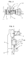
- the wrist assembly 14 will be described in detail with reference to Fig. 2 .
- the wrist assembly 14 includes a wrist base 23, a wrist 22, a flange 21, and reduction gearss 19 and 20.
- An end portion of the wrist 22 is provided on and connected to a distal end portion of the wrist base 23 with the reduction gears 19 provided therebetween such that the wrist 22 is turnable about a sixth rotation axis (6) that is perpendicular to and is on the same plane as the fifth rotation axis (5).
- An end portion of the flange 21 is provided on and connected to a distal end portion of the wrist 22 with the reduction gears 20 provided therebetween such that the flange 21 is turnable about a seventh rotation axis (7) that is perpendicular to the sixth rotation axis (6).
- FIG. 3 shows the state in which the drive motor 10 for the second upper arm 8 is detached from the second upper arm 8 to replace the drive motor 10 with another motor.
- the output shaft 10-1 and an input gear 10-2 of the drive motor 10 are fastened to the drive motor 10 for the second upper arm 8 at an end thereof to form a motor unit 10A.
- An attachment surface of the drive motor 10 is arranged such that the motor unit 10A can be completely separated from the reduction gears 9 without causing an interference between with the front arm 11 or the front-arm drive motor 13 disposed at the bottom of the front arm 11.
- the length of the second upper arm 8 is determined on the basis of the distance to the operating area. In the case where the robot is to perform an operation in an operating area that is near the robot, the length of the second upper arm 8 is determined such that the motor unit 10A can be replaced without causing an interference between the motor unit 10A and the front-arm drive motor 13.
- the lengths of the first upper arm and the second upper arm can be reduced so that the tool provided at a wrist axis can be brought closer to the robot. As a result, the robot can perform an operation in the area near the robot itself.
- a wire body 31 extends from the robot base 1 into the turning base 2, and is arranged so as to extend along a side surface of the first upper arm 5.
- the wire body 31 is fixed with a fixing clamp K1 to the side surface of the first upper arm 5 at a central position thereof, and is horizontally bent onto a rear surface of the first upper arm 5 such that a bending radius of the wire body 31 is at a minimum.
- the wire body 31 is fixed with a fixing clamp K2 to the rear surface of the first upper arm 5 at an upper end section thereof.
- the wire body 31 is vertically bent in a U-shape such that the wire body 31 extends along a side surface of the second upper arm 8, and is fixed with a fixing clamp K3 to the second upper arm 8 at a lower end section thereof.
- the wire body 31 is formed such that the width thereof is twice the bending radius of the wire body 31 when the bending radius is at a minimum. Then, the wire body 31 is horizontally bent onto a side surface of the second upper arm 8 such that the bending radius of the wire body 31 is at a minimum, and is vertically bent along the side surface of the second upper arm 8 at a central section thereof.
- the wire body 31 is fixed with a fixing clamp K4 to the second upper arm 8 at a central position thereof, and is fixed with a fixing clamp K5 provided on a support 16 to the front arm 11 at a lower end section thereof. Then, the wire body 31 is inserted into the front arm 11.
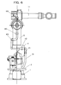
- Figs. 6 and 7 are a side view and a rear view, respectively, of the robot in the state in which the third upper arm 8 is turned by 90°.
- Reference numeral 31 denotes both a wire body for the robot and another wire body, such as a hose of cooling water or a cable for supplying electricity to the drive motors for the respective axes of the robot or a drive motor for a gun or the like (not shown) attached to a distal end portion of the robot.
- the wire bodies 31 are fixed to the turning base 2 at an exit section thereof.
- the wire bodies 31 are arranged so as to extend to a rear section of the turning base 2 and are then bent in a U-shape so that a large bending radius can be obtained during the rotation about the second rotation axis (2). Then, the wire bodies 31 are fixed to a side surface of the turning base 2 at positions separated from the rotation center at the second rotation axis (2).
- the wire bodies 31 fixed to the side surface of the turning base 2 are arranged so as to extend through an area around the rotation center at the second axis (2) and are fixed with fixing clamps K1 to a side surface of the first upper arm 5 such that the wire bodies 31 extend along the longitudinal direction of the first upper arm 5.
- the wire bodies 31 are fixed with fixing clamps K2 to a rear section of the first upper arm 5 at the upper end section thereof.
- the wire bodies 31 fixed to the rear section of the first upper arm 5 are bent in a U-shape and are fixed with fixing clamps K3 to a rear section of the second upper arm 8 at the lower end section thereof.
- the wire bodies 31 are fixed with fixing clamps K4 to a side surface of the second upper arm 8 such that the wire bodies 31 extend along the longitudinal direction of the second upper arm 8.
- the wire bodies 31 fixed to the side surface of the second upper arm 8 are arranged so as to extend through an area around the fourth rotation axis (4) and are fixed with fixing clamps K5 to a support 16 which protrudes rearward from a base portion of the front arm 11.
- the two wire bodies 31 include a robot wire body 311 necessary for driving the robot and a tool wire body 312 necessary for a gun or the like that is attached to an end portion of the robot.
- the tool wire body 312 is disposed on either the outer side or the inner side of the robot wire body 312 at movable sections of the robot. The method for arranging the wire bodies will now be described. Movements of the wire bodies 31 during the rotation about the fourth rotation axis (4) will be described with reference to Figs. 10 and 11 .
- Fig. 10 shows the state in which the front arm 11 is tilted downward by a maximum amount
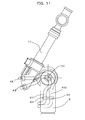
- Fig. 11 shows the state in which the front arm 11 is tilted upward by a maximum amount.
- the fixing clamp K5 for the robot wire body 311 is positioned such that the robot wire body 311 extends linearly in the state shown in Fig. 10 . Therefore, the wire bodies 31 are bent only in one direction instead of being bent in opposite directions.
- the length of the wire body 31 between the fixing clamp K4 and the fixing clamp K5 for the robot wire body 311 is determined by the linear length of the robot wire body 311 as shown in Fig.
- the position and the length of the wire body 31 between the fixing clamp K4 and the fixing clamp K5 for the tool wire body 312 is set such that the tool wire body 312 does not come into contact with the robot wire body 311 and receive a force, such as a compressive force or a tensile force, when the front arm 11 rotates about the fourth rotation axis (4).
- the tool wire body 312 is fixed by the fixing clamp K5 at a position separated from the robot wire body 311 to prevent a contact therewith.
- the tool wire body 312 is fixed by the fixing clamp K5 at a position separated from the robot wire body 311 by an amount corresponding to the curvature R obtained when the robot wire body 311 is bent as shown in Fig. 11 .
- the length of the tool wire body 312 between the fixed points thereof is set such that the tool wire body 312 can extend along the outer side of the robot wire body 311 without applying a force to the robot wire body 312 in the state shown in Fig. 11 . In such a case, the robot wire body 312 and the tool wire body 312 are prevented from receiving an excessive force, and breakage thereof can be prevented.
- the length of the tool wire body 312 is set in accordance with the movable angle range of the front arm 11 around the fourth rotation axis (4). Movements of the cables during the rotation about the third axis will be described with reference to Figs. 12, 13 , 14, and 15 . It is assumed that the movable ranges of the second upper arm 8 around the third rotation axis (3) is ⁇ 90 degrees. Figs.
- FIGS. 12 and 13 are a side view and a top view, respectively, in the case where the rotational angle is 0 degrees.
- Figs. 14 and 15 are a side view and a top view, respectively, in the case where the rotational angle is 90 degrees.
- the position at which the tool wire body 312 is fixed to the second upper arm 8 by the fixing clamp K3 is directly above the fixing clamp K2 on the first upper arm 5 in the state shown in Fig. 12 .
- the height of the fixing clamp K3 is set such that the wire body 31 can be bent at a minimum bending radius. More specifically, the vertical distance between the fixing clamp K2 and the fixing clamp K4 for the tool wire body 312 is twice the cable bending radius.
- the length of the tool wire body 312 between the fixing clamp K2 and the fixing clamp K4 is set such that the bending radius is prevented from being reduced to below the minimum bending radius of the wire body 31 at the fixing clamp K3 on the first upper arm 5 when the rotational angle around the third axis is 90 degrees as shown n Fig. 14 .
- the robot wire body 311 is fixed to the first upper arm 5 at a position directly below the tool wire body 312, and is fixed to the second upper arm 8 at a position directly above the tool wire body 312.
- the length of the robot wire body 312 between the fixing clamp K2 and the fixing clamp K4 is determined such that the robot wire body 311 extends along the robot wire body 311 without applying a compressive force to the tool wire body 312. Since the movable range is about ⁇ 90 degrees and the lengths of the U-shaped portions of the cables are not long, the cables can be prevented from protruding or becoming slack by a large amount. According to the present embodiment, the movable range of the second upper arm around the third rotation axis is assumed to be ⁇ 90 degrees. However, the movable range may, of course, also be wider or narrower than the above-described range. In such a case, the lengths of the wire bodies at the movable sections are adjusted in accordance with the movable range.
- the drive motor 10 for driving the second upper arm 8 is inclined by 90° with respect to the third rotation axis (3) and is attached to a rear surface of the robot.
- a driving force of a drive motor 10 is transmitted to a reduction gears 9 through a gear 10-2 attached to an end portion of an output shaft 10-1 and a gear 9-1 attached to an input shaft of the reduction gears 9.
- the rotation of the drive motor 10 is transmitted to the reduction gears 9 through the gear 10-1, which is a bevel gear, of the reduction gears and the input gear 9-1, which is also a bevel gear, of the reduction gears 9 that is integrated with the second upper arm 8.
- the second upper arm 8 is rotated to a predetermined angle.
- the length of the second upper arm 8 is determined on the basis of the distance to the operating area.
- the length of the second upper arm 8 is determined such that the drive motor 10 can be replaced without causing an interference between the drive motor 10 and the front-arm drive motor 13. Accordingly, in the case where the robot is to perform an operation in a narrow operating area, the length of the second upper arm 8 can be reduced. As a result, the height of the robot from the ground surface can be reduced compared to that of the robot according to the first embodiment.
- the lengths of the first upper arm and the second upper arm can be reduced to bring the tool provided at the wrist axis closer to the robot.
- the robot can perform the operation in an area closer to the robot itself.
- the displacements caused by the process of replacing the drive motor 10 can be corrected simply by making an adjustment so that the input gear 9-1 of the reduction gears 9 meshes with the gear 10-2 of the drive motor 10.
- the correction can be performed in a short time.
- the motor replacing process can be performed simply by detaching the drive motor 10, and no displacements of the joint axes of the robot occur. Therefore, the process of teaching the robot can be omitted and the manufacturing line can be restored in a short time.
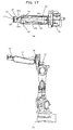
- FIG. 17 A difference between a third embodiment of the present invention shown in Fig. 17 and the first embodiment will be described with reference to Fig. 17 .
- Fig. 17 (a) is a top view and (b) is a side view.
- An attachment surface on which a drive motor 15 for rotating a wrist assembly 14 about a fifth rotation axis (5) is located at an end of a front arm 11 that is opposite to the wrist assembly 14.
- the drive motor 15 is connected to an input shaft of a reduction gears 18 that is provided at an end face of the front arm 11 with a shaft and a gear or a pulley (not shown) provided therebetween.
- the reduction gears 18 is provided with a hole through which a cable can be inserted.
- the reduction gears 18 is secured to both the end face of the front arm 11 and an end portion of the wrist assembly 14, and is rotatably supported.
- the wrist assembly 14 will be described in detail with reference to Fig. 17(a) .
- the wrist assembly 14 includes a wrist base 23, a wrist 22, a flange 21, and reduction gearss 19 and 20.
- the wrist base 23 includes two members 23a and 23b and has a shape of a substantially U-shaped fork. A space through which a cable extends is provided between the two members.
- the wrist 22 includes two members 22a and 22b that extend parallel to a seventh rotation axis (7), and has a shape of a two-tined fork such that a space through which a cable extends is provided between the two members.
- An end portion of the flange 21 is provided on and connected to a distal end portion of the wrist 22 with the reduction gears 20 provided therebetween such that the flange 21 is turnable about the seventh rotation axis (7) that is perpendicular to the sixth rotation axis (6).
- a drive motor for the wrist 22 and a drive motor for the flange are connected to input shafts of the reduction gearss 19 and 20, respectively, through shafts and gears or pulleys (not shown).
Landscapes
- Engineering & Computer Science (AREA)
- Robotics (AREA)
- Mechanical Engineering (AREA)
- Manipulator (AREA)
Abstract
A vertical articulated robot includes a base 1, a turning base 2 provided on the base 1 so as to be pivotable about a first rotation axis (1); a first upper arm 5 provided on the turning base 2 so as to be turnable about a second rotation axis (2) that is in a plane perpendicular to the first rotation axis (1); a second upper arm 8 provided on a distal end portion of the first upper arm 5 so as to be pivotable about a third rotation axis (3) that is perpendicular to the second rotation axis (2); a front arm provided on a distal end portion of the second upper arm 8 so as to be turnable about a fourth rotation axis (4) that is in a plane perpendicular to the third rotation axis (3); a wrist assembly 14 mounted on a distal end portion of the front arm; and motors that rotate the first upper arm 5, the second upper arm 8, and the front arm about the respective rotation axes. The motor 10 that rotates the second upper arm 8 is mounted on a frame of the second upper arm 8.
Description
- The present invention relates to a vertical articulated robot having a redundant axis.
- Recent industrial robots are required to perform processes of welding, applying sealing agents, assembling parts, etc., by inserting a wrist assembly, which holds an operating tool, and a part of an arm supporting the wrist assembly into, for example, an automobile body. Therefore, there have been demands for robots that have smaller wrist portions and arms with smaller diameters and that are capable of performing high-speed, high-precision operations. In addition, in a conventional multi-joint robot placed on a surface, such as a floor surface, a plane including an upper arm and a front arm is always in a vertical orientation, and there is a risk that the arms will interfere with an obstacle or the like placed on an approach route thereof, depending on an area into which the arms are to be inserted in the operation. Therefore, it is desirable to increase the flexibility of movement of the arms such that the orientation of the plane including the upper arm and the front arm can be changed to an arbitrary orientation, such as a horizontal orientation.
In addition, the industrial robots are and have been required to complete the processes of welding, applying sealing agents, assembling parts, etc., in a shorter time to increase the process throughput and comply with the increase in the numbers of products to be produced and production steps. The requirement regarding the throughput is not only to complete each production step in a short time but also to allow maintenance of the robot, which is operated around the clock, to be completed in a short time. To improve the productivity, it is important to increase the operating time of the robot and complete each production step in a short time.
In recent manufacturing lines including industrial robots, the robots are collectively arranged to reduce the space for the manufacturing processes. However, a conventional industrial robot that does not have a redundant axis cannot bring a tool provided at a wrist axis of the robot to a position near the robot itself. Therefore, even when multiple robots are collectively arranged, the robots cannot perform processes in areas near themselves and operating areas cannot be increased. To overcome such a problem, robots having redundant axes have been developed. Additionally, there has been a demand for a robot capable of performing an operation in an area close to the robot itself in consideration of an arm length.
The industrial robots capable of moving flexibly are required to perform complex movements in an environment where the robots are densely arranged, and accordingly the industrial robots have complex structures. On the contrary, the robots are also required to allow easy maintenance.
As an example of a vertical articulated robot according to the related art, a seven-degree-of-freedom robot with which the problem of flexibility can be solved has been proposed (see, for example, Patent Document 1). This vertical articulated robot includes a base; a turning base provided on the base so as to be pivotable about a first rotation axis; a first upper arm provided on the turning base so as to be turnable about a second rotation axis that is in a plane perpendicular to the first rotation axis; a second upper arm provided on a distal end portion of the first upper arm so as to be pivotable about a third rotation axis that is perpendicular to the second rotation axis; a front arm provided on a distal end portion of the second upper arm so as to be turnable about a fourth rotation axis that is in a plane perpendicular to the third rotation axis; a wrist assembly mounted on a distal end portion of the front arm; and motors that rotate the first upper arm, the second upper arm, and the front arm about the respective rotation axes.
The seven-degree-of-freedom vertical articulated robot according to the related art is capable of avoiding interference with a workpiece or peripheral devices and interference between the arms, and the operating area around the robot can be effectively utilized. - [Patent Document 1] Japanese Patent No.
2585425 page 4 andFigs. 3 and4 ) - In the vertical articulated robot according to the related art, the drive motor for turning the second upper arm is disposed in the second upper arm 103. Alternatively, an inner stator and an outer rotor of the drive motor for the second upper arm are fixed to the first upper arm and the second upper arm, respectively. The second upper arm is turned about the third rotation axis that is perpendicular to the second rotation axis. Therefore, the drive motor cannot be replaced unless the second upper arm is separated from the robot, and there is a problem that it takes a long time to replace the drive motor. Even if it is not necessary to replace the drive motor, it is necessary to regularly apply grease to a reduction gears. Also in this case, it is necessary to separate the second upper arm from the robot. If it is necessary to perform a major process such as separation of the second upper arm in the maintenance operation, a long maintenance time is necessary and the manufacturing line must be stopped during the maintenance time. Therefore, there is a problem that the productivity will be reduced.
When the drive motor is replaced with another drive motor, the first upper arm and the second upper arm are separated from each other. Therefore, the first and second upper arms may become mechanically displaced from each other. In such a case, to correct the displacement, it is necessary to teach trajectories to the robot again. In general, it takes several hours to teach a single robot; therefore, it may take days to teach several tens of robots included in a manufacturing line. During that time period, the manufacturing line must be stopped, which leads to a reduction in productivity.
Since the drive motors are disposed in the arms, wiring lines for respective axes are connected to the motors in the arm bodies. However, there is a risk that the wiring lines will break when the arms rotate. To repair or replace the broken cables, it is necessary to disassemble the robot. In such a case, a long maintenance time is necessary and the manufacturing line will be stopped.
In view of the above-described problems, an object of the present invention is to provide a vertical articulated robot in which a drive motor or a cable can be replaced in a short time, which can readily correct mechanical displacements, and which can perform an operation in an area near the robot. - To solve the above-described problems, according to the present invention, the following structures are provided.
According to the invention ofclaim 1, a vertical articulated robot includes a base; a turning base provided on the base so as to be pivotable about a first rotation axis; a first upper arm provided on the turning base so as to be turnable about a second rotation axis that is in a plane perpendicular to the first rotation axis; a second upper arm provided on a distal end portion of the first upper arm so as to be pivotable about a third rotation axis that is perpendicular to the second rotation axis; a front arm provided on a distal end portion of the second upper arm so as to be turnable about a fourth rotation axis that is in a plane perpendicular to the third rotation axis; a wrist assembly mounted on a distal end portion of the front arm; and motors that rotate the first upper arm, the second upper arm, the front arm, and the wrist assembly about the respective rotation axes. The motor that rotates the second upper arm is mounted on a frame of the second upper arm.
According to the invention ofclaim 2, in the state in which the first upper arm is in a vertical orientation, the motor that rotates the second upper arm is mounted on the frame of the second upper arm such that a rotating shaft of the motor extends perpendicular to a ground surface and such that an output shaft of the motor faces toward the ground surface.
According to the invention ofclaim 3, in the state in which the first upper arm is in a vertical orientation, the motor that rotates the second upper arm is mounted on a rear surface of the frame of the second upper arm such that a rotating shaft of the motor extends parallel to a ground surface.
According to the invention ofclaim 4, the distal end portion of the first upper arm is provided with a reduction gears that rotates the second upper arm and is formed in an inverted L-shape.
According to the invention ofclaim 5, the second upper arm is provided with the motor that rotates the second upper arm and is formed in an L-shape.
According to the invention ofclaim 6, in the case where the robot is to perform an operation in an operating area that is distant from the robot, a length of the first upper arm is determined on the basis of a distance to the operating area. In the case where the robot is to perform an operation in an operating area that is near the robot, the length of the first upper arm is determined such that a process of replacing a motor unit can be performed without causing an interference between the motor unit and an upper end portion of the first upper arm.
According to the invention ofclaim 7, in the case where the robot is to perform an operation in an operating area that is distant from the robot, a length of the second upper arm is determined on the basis of a distance to the operating area. In the case where the robot is to perform an operation in an operating area that is near the robot, the length of the second upper arm is determined such that a process of replacing a motor unit can be performed without causing an interference between the motor unit and the motor that drives the front arm.
According to the invention ofclaim 8, in the state in which the first upper arm is in a vertical orientation, the motor that rotates the second upper arm is mounted on the frame of the second upper arm such that a rotating shaft of the motor extends perpendicular to a ground surface and such that an output shaft of the motor faces toward the ground surface. The output shaft of the motor is provided with an input gear that meshes with the reduction gears provided on the first upper arm.
According to the invention ofclaim 9, the motor that rotates the second upper arm is, the motor that rotates the second upper arm is mounted on a rear surface of the frame of the second upper arm such that a rotating shaft of the motor extends parallel to a ground surface. Power is transmitted through a bevel gear train between an output shaft of the motor and a reduction gears provided on the first upper arm.
According to the invention of claim 10 a vertical articulated robot includes a base; a turning base provided on the base so as to be pivotable about a first rotation axis; a first upper arm provided on the turning base so as to be turnable about a second rotation axis that is in a plane perpendicular to the first rotation axis; a second upper arm provided on a distal end portion of the first upper arm so as to be pivotable about a third rotation axis that is perpendicular to the second rotation axis; a front arm provided on a distal end portion of the second upper arm so as to be turnable about a fourth rotation axis that is in a plane perpendicular to the third rotation axis; a wrist assembly mounted on a distal end portion of the front arm; and motors that rotate the first upper arm, the second upper arm, the front arm, and the wrist assembly about the respective rotation axes. A wire body that extends from the turning base is arranged so as to extend along a side surface of the first upper arm, is fixed to the side surface of the first upper arm at a central section of the first upper arm, is bent horizontally onto a rear surface of the first upper arm, and is fixed to the rear surface of the first upper arm at an upper end position of the first upper arm. The wire body is bent vertically in a U-shape so as to extend along a side surface of the second upper arm, is fixed to the second upper arm at a lower end position of the second upper arm, is bent horizontally so as to extend along another side surface of the second upper arm, is bent vertically at the center of the another side surface of the second upper arm, is fixed to the second upper arm at a central section of the second upper arm, is fixed to the front arm at a lower end position of the front arm, and extends into the front arm. - According to the invention described in
claims 1 to 9, since the robot has a redundant axis, processes of welding, applying sealing agents, assembling parts, etc., can be performed without causing an interference with an obstacle. Therefore, the versatility of the manufacturing line can be increased. In addition, since the motor that drives the second upper arm is mounted on the frame of the second upper arm, the motor is exposed to the outside. Therefore, the motor can be readily replaced with another motor and the time required for the replacing process can be reduced.
In addition, since the motor replacing process can be performed simply by removing the motor, it is not necessary to remove the arms. Therefore, no mechanical displacements occur between the arms, and it is not necessary to teach trajectories to the robot again when the robot is operated after the motor replacing process. As a result, the manufacturing line can be restored in a short time.
As described above, since the motor can be replaced with another motor in a short time, the operating time of the robot can be increased and the productivity can be improved.
In addition, according to the invention described inclaims
According to the invention described inclaim 10, a transmission line connected to the drive motors or the operating tool provided at the wrist axis is arranged such that the transmission line does not protrude outward from the robot irrespective of the operational state. Therefore, the size of the robot can be set to a minimum size and maintenance of wiring lines can be facilitated at the same time. -
- [
Fig. 1] Fig. 1 shows a side view and a front view of a first embodiment of the present invention. - [
Fig. 2] Fig. 2 is a top view illustrating a wrist assembly according to the first embodiment of the present invention. - [
Fig. 3] Fig. 3 is a sectional view of a second upper arm according to the first embodiment of the present invention. - [
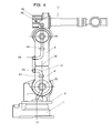
Fig. 4] Fig. 4 is a side view illustrating the arrangement of a wire body according to the first embodiment of the present invention. - [
Fig. 5] Fig. 5 is a rear view illustrating the arrangement of the wire body according to the first embodiment of the present invention. - [
Fig. 6] Fig. 6 is a side view illustrating the arrangement of the wire body according to the first embodiment of the present invention in the state in which a third rotation axis is rotated by 90 degrees. - [
Fig. 7] Fig. 7 is a rear view illustrating the arrangement of the wire body according to the first embodiment of the present invention in the state in which the third rotation axis is rotated by 90 degrees. - [
Fig. 8] Fig. 8 is a rear view illustrating the arrangement of wire bodies according to the first embodiment of the present invention. - [
Fig. 9] Fig. 9 is a side view illustrating the arrangement of the wire bodies according to the first embodiment of the present invention. - [
Fig. 10] Fig. 10 is a side view illustrating the arrangement of the wire bodies according to the first embodiment of the present invention in the state in which a front arm is tilted downward. - [
Fig. 11] Fig. 11 is a side view illustrating the arrangement of the wire bodies according to the first embodiment of the present invention in the state in which the front arm is tilted upward. - [
Fig. 12] Fig. 12 is a side view illustrating the arrangement of the wire bodies according to the first embodiment of the present invention in the state in which the third rotation axis is rotated by 0 degrees. - [
Fig. 13] Fig. 13 is a top view illustrating the arrangement of the wire bodies according to the first embodiment of the present invention in the state in which the third rotation axis is rotated by 0 degrees. - [
Fig. 14] Fig. 14 is a side view illustrating the arrangement of the wire bodies according to the first embodiment of the present invention in the state in which the third rotation axis is rotated by 90 degrees. - [
Fig. 15] Fig. 15 is a top view illustrating the arrangement of the wire bodies according to the first embodiment of the present invention in the state in which the third rotation axis is rotated by 90 degrees. - [
Fig. 16] Fig. 16 is a side view of a seven-degree-of-freedom vertical articulated robot according to a second embodiment of the present invention. - [
Fig. 17] Fig. 17 shows a side view and a top view of a seven-degree-of-freedom vertical articulated robot according to a third embodiment of the present invention. -
- 1
- base
- 2
- turning base
- 3, 6, 9, 12, 18, 19, 20
- reduction gears
- 4, 7, 10, 13, 15
- drive motor
- 4-1, 7-1, 10-1, 13-1
- output shaft
- 5
- first upper arm
- 8
- second upper arm
- 9-1
- gear
- 7A, 10A
- motor unit
- 10-2
- input gear
- 11
- front arm
- (1) to (7)
- rotation axis
- 14
- wrist assembly
- 16
- support
- 21
- flange
- 22
- wrist
- 22a, 22b
- member
- 23
- wrist base
- 23a, 23b
- member
- 31
- wire body
- 311
- robot wire body
- 312
- tool wire body
- 32
- support
- K1 to K5
- fixing clamp
- Embodiments of the present invention will be described with reference to the drawings.
-
Fig. 1 shows a seven-degree-of-freedom vertical articulated robot according to an embodiment of the present invention, where (a) is a side view and (b) is a front view of the robot. In the figure, a rotation axis (1) is perpendicular to the ground surface. A turningbase 2 is provided with a turningdrive motor 4 attached thereto, and an output shaft 4-1 of the turningdrive motor 4 is connected to an input shaft of a reduction gears 3. The reduction gears 3 is a turning reduction gears and is supported by arobot base 1 and theturning base 2 such that thebase 1 and theturning base 2 are relatively pivotable. The turningbase 2 and the reduction gears 3 are arranged on the rotation axis (1).
Adrive motor 7 for a firstupper arm 5 is arranged on a second rotation axis (2) in an opening provided in the above-describedturning base 2. The second rotation axis (2) is in a plane perpendicular to the rotation axis (1).
An output shaft 7-1 of thedrive motor 7 for the firstupper arm 5 is connected to an input shaft of a reduction gears 6 for the firstupper arm 5. The reduction gears 6 for the first upper arm is secured to both the opening in theturning base 2 and a side surface of the firstupper arm 5, and is supported so as to be turnable about the second rotation axis (2).
The firstupper arm 5 has an inverted L shape such that an L-shaped member is vertically inverted. An upper end portion of the firstupper arm 5 supports a secondupper arm 8 with a reduction gears 9 interposed therebetween. The reduction gears 9 is arranged on a third rotation axis (3) that is perpendicular to the second rotation axis (2) and that is on the same plate as the first rotation axis (1). The secondupper arm 8 is supported so as to be turnable about the third rotation axis (3). With this structure, thedrive motor 7 for the firstupper arm 5 can be arranged such that thedrive motor 7 does not protrude from the robot in the width direction thereof when viewed from the front. In the case where the robot is to perform an operation in an operating area that is distant from the robot, the length of the firstupper arm 5 is determined on the basis of the distance to the operating area. In the case where the robot is to perform an operation in an operating area that is near the robot, the length of the firstupper arm 5 is determined such that amotor unit 7A can be replaced without causing an interference between themotor unit 7A and the upper end portion of the firstupper arm 5.
The secondupper arm 8 has an L-shape that is symmetric to the shape of the firstupper arm 5, so that adrive motor 10 for the second upper arm can be attached to the secondupper arm 8 on the third rotation axis (3). Thus, thedrive motor 10 for turning the secondupper arm 8 is attached to the secondupper arm 8. Since the secondupper arm 8 has an L-shape as described above, thedrive motor 10 for the secondupper arm 8 can be arranged such that thedrive motor 10 does not protrude from robot in the width direction thereof when viewed from the front. An output shaft 10-1 of thedrive motor 10 for turning the secondupper arm 8 is connected to an input shaft of the reduction gears 9 for the firstupper arm 8. The reduction gears 9 for the secondupper arm 8 is secured to both the upper end portion of the firstupper arm 5 and the bottom surface of the secondupper arm 8, and is supported so as to be pivotable.
A fourth rotation center (4) is perpendicular to and is on the same plane as the third rotation axis (3). Adrive motor 13 and a reduction gears 12 for afront arm 11 are arranged on the fourth rotation axis.
A lower end portion of thefront arm 11, which is positioned above the secondupper arm 8, is rotatably supported in an upper opening in the secondupper arm 8 with the reduction gears 12 provided between thefront arm 11 and the secondupper arm 8.
An output shaft 13-1 of thedrive motor 13 for thefront arm 11 is connected to an input shaft of the reduction gears 12 for thefront arm 11. The reduction gears 12 for thefront arm 11 is secured to both an opening in thefront arm 11 and a side surface of the secondupper arm 8, and is rotatably supported.
A rotation axis (5) is in a plane that is perpendicular to the rotation axis (4) and on which the third rotation axis (3) is arranged.
An attachment surface on which adrive motor 15 for rotating awrist assembly 14 about the rotation axis (5) is located at an end of thefront arm 11 that is opposite to thewrist assembly 14. Thedrive motor 15 is connected to an input shaft of a reduction gears provided at an end face of thefront arm 11 with a shaft and a gear or a pulley (not shown) provided therebetween. The reduction gears is secured to both the end face of thefront arm 11 and an end portion of thewrist assembly 14, and is rotatably supported.
Thewrist assembly 14 will be described in detail with reference toFig. 2 . Thewrist assembly 14 includes awrist base 23, awrist 22, aflange 21, and reduction gearss 19 and 20. An end portion of thewrist 22 is provided on and connected to a distal end portion of thewrist base 23 with the reduction gears 19 provided therebetween such that thewrist 22 is turnable about a sixth rotation axis (6) that is perpendicular to and is on the same plane as the fifth rotation axis (5). An end portion of theflange 21 is provided on and connected to a distal end portion of thewrist 22 with the reduction gears 20 provided therebetween such that theflange 21 is turnable about a seventh rotation axis (7) that is perpendicular to the sixth rotation axis (6). A drive motor (not shown) for thewrist 22 shown inFig. 1 and a drive motor for the flange are connected to input shafts of thereduction gearss
Fig. 3 shows the state in which thedrive motor 10 for the secondupper arm 8 is detached from the secondupper arm 8 to replace thedrive motor 10 with another motor. Referring to the figure, the output shaft 10-1 and an input gear 10-2 of thedrive motor 10 are fastened to thedrive motor 10 for the secondupper arm 8 at an end thereof to form amotor unit 10A. An attachment surface of thedrive motor 10 is arranged such that themotor unit 10A can be completely separated from the reduction gears 9 without causing an interference between with thefront arm 11 or the front-arm drive motor 13 disposed at the bottom of thefront arm 11. In the case where the robot is to perform an operation in an operating area that is distant from the robot, the length of the secondupper arm 8 is determined on the basis of the distance to the operating area. In the case where the robot is to perform an operation in an operating area that is near the robot, the length of the secondupper arm 8 is determined such that themotor unit 10A can be replaced without causing an interference between themotor unit 10A and the front-arm drive motor 13.
Thus, in the case where the robot is to perform an operation in an operating area that is near the robot, the lengths of the first upper arm and the second upper arm can be reduced so that the tool provided at a wrist axis can be brought closer to the robot. As a result, the robot can perform an operation in the area near the robot itself.
The displacements caused by the process of replacing themotor unit 10A can be corrected simply by making an adjustment so that the reduction gears 9 meshes with the input gear 10-2. Therefore, the correction can be performed in a short time. As described above, thedrive motor 10 can be replaced simply by detaching themotor unit 10A, and no displacements of the joint axes of the robot occur. Therefore, the process of teaching the robot can be omitted and the manufacturing line can be restored in a short time.
Next, the process of arranging a cable will be described with reference toFigs. 4 and5 . Awire body 31 extends from therobot base 1 into theturning base 2, and is arranged so as to extend along a side surface of the firstupper arm 5. Thewire body 31 is fixed with a fixing clamp K1 to the side surface of the firstupper arm 5 at a central position thereof, and is horizontally bent onto a rear surface of the firstupper arm 5 such that a bending radius of thewire body 31 is at a minimum. Thewire body 31 is fixed with a fixing clamp K2 to the rear surface of the firstupper arm 5 at an upper end section thereof.
Then, thewire body 31 is vertically bent in a U-shape such that thewire body 31 extends along a side surface of the secondupper arm 8, and is fixed with a fixing clamp K3 to the secondupper arm 8 at a lower end section thereof. At this time, thewire body 31 is formed such that the width thereof is twice the bending radius of thewire body 31 when the bending radius is at a minimum.
Then, thewire body 31 is horizontally bent onto a side surface of the secondupper arm 8 such that the bending radius of thewire body 31 is at a minimum, and is vertically bent along the side surface of the secondupper arm 8 at a central section thereof. Thewire body 31 is fixed with a fixing clamp K4 to the secondupper arm 8 at a central position thereof, and is fixed with a fixing clamp K5 provided on a support 16 to thefront arm 11 at a lower end section thereof. Then, thewire body 31 is inserted into thefront arm 11.
In the case where thewire body 31 is arranged as described above, when the secondupper arm 8 is turned about the third rotation axis (3), thewire body 31 moves between the fixing clamp K2 at the upper end section of the firstupper arm 5 and the fixing clamp K3 at the lower end section of the secondupper arm 8. Assuming that the movable range of the secondupper arm 8 is from +90 degrees to -90 degrees, thewire body 31 that is fixed in the above-described manner does not protrude outward or become slack by an excessive amount in the operation of the robot. This will be described with reference toFigs. 6 and7 .
Figs. 6 and7 are a side view and a rear view, respectively, of the robot in the state in which the thirdupper arm 8 is turned by 90°. InFigs. 6 and7 , when the secondupper arm 8 is turned, thewire body 31 is fixed with the fixing clamp K2 provided at the upper end section of the firstupper arm 5 and the fixing clamp K3 provided at the lower end section of the secondupper arm 8 such that thewire body 31 is bent so as to extend between the fixing clamp K2 and the fixing clamp K3 along the outer peripheral surfaces of the arms while the width of thewire body 31 is maintained at twice the bending radius of thewire body 31. Since the wire body is fixed so as to extend along the peripheral surfaces of the arms, the amount by which the wire body protrudes outward can be reduced. As a result, the risk that the wire body will protrude outward and interfere with a peripheral device or the robot itself can be reduced.
Although the arrangement of a single wire body is described in the above-described embodiment, two or more wire bodies may also be provided. A case in which two wire bodies are arranged will now be described with reference toFigs. 8 and9 .Reference numeral 31 denotes both a wire body for the robot and another wire body, such as a hose of cooling water or a cable for supplying electricity to the drive motors for the respective axes of the robot or a drive motor for a gun or the like (not shown) attached to a distal end portion of the robot.
Thewire bodies 31 are fixed to theturning base 2 at an exit section thereof. Thewire bodies 31 are arranged so as to extend to a rear section of theturning base 2 and are then bent in a U-shape so that a large bending radius can be obtained during the rotation about the second rotation axis (2). Then, thewire bodies 31 are fixed to a side surface of theturning base 2 at positions separated from the rotation center at the second rotation axis (2). Thewire bodies 31 fixed to the side surface of theturning base 2 are arranged so as to extend through an area around the rotation center at the second axis (2) and are fixed with fixing clamps K1 to a side surface of the firstupper arm 5 such that thewire bodies 31 extend along the longitudinal direction of the firstupper arm 5. Then, thewire bodies 31 are fixed with fixing clamps K2 to a rear section of the firstupper arm 5 at the upper end section thereof. Thewire bodies 31 fixed to the rear section of the firstupper arm 5 are bent in a U-shape and are fixed with fixing clamps K3 to a rear section of the secondupper arm 8 at the lower end section thereof. Then, thewire bodies 31 are fixed with fixing clamps K4 to a side surface of the secondupper arm 8 such that thewire bodies 31 extend along the longitudinal direction of the secondupper arm 8. Thewire bodies 31 fixed to the side surface of the secondupper arm 8 are arranged so as to extend through an area around the fourth rotation axis (4) and are fixed with fixing clamps K5 to a support 16 which protrudes rearward from a base portion of thefront arm 11.
In consideration of the ease of maintenance, at least twowire bodies 31 are provided. The twowire bodies 31 include arobot wire body 311 necessary for driving the robot and atool wire body 312 necessary for a gun or the like that is attached to an end portion of the robot.
According to the present invention, to reduce the width of robots so that the robots can be densely arranged, thetool wire body 312 is disposed on either the outer side or the inner side of therobot wire body 312 at movable sections of the robot. The method for arranging the wire bodies will now be described.
Movements of thewire bodies 31 during the rotation about the fourth rotation axis (4) will be described with reference toFigs. 10 and11 . Movements during the rotation about the second rotation axis are the same as those in the rotation about the fourth rotation axis, and explanations thereof are thus omitted.
Fig. 10 shows the state in which thefront arm 11 is tilted downward by a maximum amount, andFig. 11 shows the state in which thefront arm 11 is tilted upward by a maximum amount.
The fixing clamp K5 for therobot wire body 311 is positioned such that therobot wire body 311 extends linearly in the state shown inFig. 10 . Therefore, thewire bodies 31 are bent only in one direction instead of being bent in opposite directions. The length of thewire body 31 between the fixing clamp K4 and the fixing clamp K5 for therobot wire body 311 is determined by the linear length of therobot wire body 311 as shown inFig. 10 , so that there is no loss in the length of therobot wire body 311.
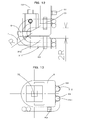
The position and the length of thewire body 31 between the fixing clamp K4 and the fixing clamp K5 for thetool wire body 312 is set such that thetool wire body 312 does not come into contact with therobot wire body 311 and receive a force, such as a compressive force or a tensile force, when thefront arm 11 rotates about the fourth rotation axis (4). Thetool wire body 312 is fixed by the fixing clamp K5 at a position separated from therobot wire body 311 to prevent a contact therewith. More specifically, thetool wire body 312 is fixed by the fixing clamp K5 at a position separated from therobot wire body 311 by an amount corresponding to the curvature R obtained when therobot wire body 311 is bent as shown inFig. 11 . In addition, the length of thetool wire body 312 between the fixed points thereof is set such that thetool wire body 312 can extend along the outer side of therobot wire body 311 without applying a force to therobot wire body 312 in the state shown inFig. 11 . In such a case, therobot wire body 312 and thetool wire body 312 are prevented from receiving an excessive force, and breakage thereof can be prevented. However, since thetool wire body 312 is longer than therobot wire body 311, thetool wire body 312 becomes slack in the state shown inFig. 10 . Therefore, to prevent breakage due to a local bending caused by an excessive slack, the length of thetool wire body 312 is set in accordance with the movable angle range of thefront arm 11 around the fourth rotation axis (4).
Movements of the cables during the rotation about the third axis will be described with reference toFigs. 12, 13 ,14, and 15 .
It is assumed that the movable ranges of the secondupper arm 8 around the third rotation axis (3) is ±90 degrees.
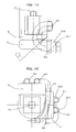
Figs. 12 and 13 are a side view and a top view, respectively, in the case where the rotational angle is 0 degrees.Figs. 14 and 15 are a side view and a top view, respectively, in the case where the rotational angle is 90 degrees.
The position at which thetool wire body 312 is fixed to the secondupper arm 8 by the fixing clamp K3 is directly above the fixing clamp K2 on the firstupper arm 5 in the state shown inFig. 12 . The height of the fixing clamp K3 is set such that thewire body 31 can be bent at a minimum bending radius. More specifically, the vertical distance between the fixing clamp K2 and the fixing clamp K4 for thetool wire body 312 is twice the cable bending radius. The length of thetool wire body 312 between the fixing clamp K2 and the fixing clamp K4 is set such that the bending radius is prevented from being reduced to below the minimum bending radius of thewire body 31 at the fixing clamp K3 on the firstupper arm 5 when the rotational angle around the third axis is 90 degrees as shown nFig. 14 .
In the states shown inFigs. 12 and 13 , therobot wire body 311 is fixed to the firstupper arm 5 at a position directly below thetool wire body 312, and is fixed to the secondupper arm 8 at a position directly above thetool wire body 312. The length of therobot wire body 312 between the fixing clamp K2 and the fixing clamp K4 is determined such that therobot wire body 311 extends along therobot wire body 311 without applying a compressive force to thetool wire body 312.
Since the movable range is about ±90 degrees and the lengths of the U-shaped portions of the cables are not long, the cables can be prevented from protruding or becoming slack by a large amount.
According to the present embodiment, the movable range of the second upper arm around the third rotation axis is assumed to be ±90 degrees. However, the movable range may, of course, also be wider or narrower than the above-described range. In such a case, the lengths of the wire bodies at the movable sections are adjusted in accordance with the movable range. - A difference between a second embodiment of the present invention shown in
Fig. 16 and the first embodiment will be described with reference toFig. 16 .
Thedrive motor 10 for driving the secondupper arm 8 is inclined by 90° with respect to the third rotation axis (3) and is attached to a rear surface of the robot. A driving force of adrive motor 10 is transmitted to a reduction gears 9 through a gear 10-2 attached to an end portion of an output shaft 10-1 and a gear 9-1 attached to an input shaft of the reduction gears 9. The rotation of thedrive motor 10 is transmitted to the reduction gears 9 through the gear 10-1, which is a bevel gear, of the reduction gears and the input gear 9-1, which is also a bevel gear, of the reduction gears 9 that is integrated with the secondupper arm 8. Accordingly, the secondupper arm 8 is rotated to a predetermined angle.
In the case where the robot is to perform an operation in an operating area that is distant from the robot, the length of the secondupper arm 8 is determined on the basis of the distance to the operating area. In the case where the robot is to perform an operation in an operating area that is near the robot, the length of the secondupper arm 8 is determined such that thedrive motor 10 can be replaced without causing an interference between thedrive motor 10 and the front-arm drive motor 13.
Accordingly, in the case where the robot is to perform an operation in a narrow operating area, the length of the secondupper arm 8 can be reduced. As a result, the height of the robot from the ground surface can be reduced compared to that of the robot according to the first embodiment. In other words, the lengths of the first upper arm and the second upper arm can be reduced to bring the tool provided at the wrist axis closer to the robot. As a result, the robot can perform the operation in an area closer to the robot itself. In addition, similar to the first embodiment, the displacements caused by the process of replacing thedrive motor 10 can be corrected simply by making an adjustment so that the input gear 9-1 of the reduction gears 9 meshes with the gear 10-2 of thedrive motor 10. Thus, the correction can be performed in a short time. As described above, the motor replacing process can be performed simply by detaching thedrive motor 10, and no displacements of the joint axes of the robot occur. Therefore, the process of teaching the robot can be omitted and the manufacturing line can be restored in a short time. - A difference between a third embodiment of the present invention shown in
Fig. 17 and the first embodiment will be described with reference toFig. 17 .
InFig. 17, (a) is a top view and(b) is a side view.
An attachment surface on which adrive motor 15 for rotating awrist assembly 14 about a fifth rotation axis (5) is located at an end of afront arm 11 that is opposite to thewrist assembly 14. Thedrive motor 15 is connected to an input shaft of a reduction gears 18 that is provided at an end face of thefront arm 11 with a shaft and a gear or a pulley (not shown) provided therebetween. The reduction gears 18 is provided with a hole through which a cable can be inserted. The reduction gears 18 is secured to both the end face of thefront arm 11 and an end portion of thewrist assembly 14, and is rotatably supported.
Thewrist assembly 14 will be described in detail with reference toFig. 17(a) . Thewrist assembly 14 includes awrist base 23, awrist 22, aflange 21, and reduction gearss 19 and 20. Thewrist base 23 includes twomembers wrist 22 is provided on and connected to a distal end portion of thewrist base 23 with the reduction gears 19 provided therebetween such that thewrist 22 is turnable about a sixth rotation axis (6) that is perpendicular to and is on the same plane as the fifth rotation axis (5). Thewrist 22 includes twomembers flange 21 is provided on and connected to a distal end portion of thewrist 22 with the reduction gears 20 provided therebetween such that theflange 21 is turnable about the seventh rotation axis (7) that is perpendicular to the sixth rotation axis (6). A drive motor for thewrist 22 and a drive motor for the flange (not shown) are connected to input shafts of thereduction gearss
Claims (10)
- A vertical articulated robot comprising a base; a turning base provided on the base so as to be pivotable about a first rotation axis; a first upper arm provided on the turning base so as to be turnable about a second rotation axis that is in a plane perpendicular to the first rotation axis; a second upper arm provided on a distal end portion of the first upper arm so as to be pivotable about a third rotation axis that is perpendicular to the second rotation axis; a front arm provided on a distal end portion of the second upper arm so as to be turnable about a fourth rotation axis that is in a plane perpendicular to the third rotation axis; a wrist assembly mounted on a distal end portion of the front arm; and motors that rotate the first upper arm, the second upper arm, the front arm, and the wrist assembly about the respective rotation axes, wherein the motor that rotates the second upper arm is mounted on a frame of the second upper arm.
- The vertical articulated robot according to claim 1, wherein, in the state in which the first upper arm is in a vertical orientation, the motor that rotates the second upper arm is mounted on the frame of the second upper arm such that a rotating shaft of the motor extends perpendicular to a ground surface and such that an output shaft of the motor faces toward the ground surface.
- The vertical articulated robot according to claim 1, wherein, in the state in which the first upper arm is in a vertical orientation, the motor that rotates the second upper arm is mounted on a rear surface of the frame of the second upper arm such that a rotating shaft of the motor extends parallel to a ground surface.
- The vertical articulated robot according to claim 1, wherein the distal end portion of the first upper arm is provided with a reduction gears that rotates the second upper arm and is formed in an inverted L-shape.
- The vertical articulated robot according to claim 1, wherein the second upper arm is provided with the motor that rotates the second upper arm and is formed in an L-shape.
- The vertical articulated robot according to claim 1, wherein, in the case where the robot is to perform an operation in an operating area that is distant from the robot, a length of the first upper arm is determined on the basis of a distance to the operating area, and wherein, in the case where the robot is to perform an operation in an operating area that is near the robot, the length of the first upper arm is determined such that a process of replacing a motor unit can be performed without causing an interference between the motor unit and an upper end portion of the first upper arm.
- The vertical articulated robot according to claim 1, wherein, in the case where the robot is to perform an operation in an operating area that is distant from the robot, a length of the second upper arm is determined on the basis of a distance to the operating area, and wherein, in the case where the robot is to perform an operation in an operating area that is near the robot, the length of the second upper arm is determined such that a process of replacing a motor unit can be performed without causing an interference between the motor unit and the motor that drives the front arm.
- The vertical articulated robot according to claim 1, wherein the motor that rotates the second upper arm is mounted on the frame of the second upper arm such that a rotating shaft of the motor extends perpendicular to a ground surface and such that an output shaft of the motor faces toward the ground surface, and wherein the output shaft of the motor is provided with an input gear that meshes with the reduction gears provided on the first upper arm.
- The vertical articulated robot according to claim 1, wherein the motor that rotates the second upper arm is mounted on a rear surface of the frame of the second upper arm such that a rotating shaft of the motor extends parallel to a ground surface, and wherein power is transmitted through a bevel gear train between an output shaft of the motor and a reduction gears provided on the first upper arm.
- A vertical articulated robot comprising a base; a turning base provided on the base so as to be pivotable about a first rotation axis; a first upper arm provided on the turning base so as to be turnable about a second rotation axis that is in a plane perpendicular to the first rotation axis; a second upper arm provided on a distal end portion of the first upper arm so as to be pivotable about a third rotation axis that is perpendicular to the second rotation axis; a front arm provided on a distal end portion of the second upper arm so as to be turnable about a fourth rotation axis that is in a plane perpendicular to the third rotation axis; a wrist assembly mounted on a distal end portion of the front arm; and motors that rotate the first upper arm, the second upper arm, the front arm, and the wrist assembly about the respective rotation axes, wherein a wire body that extends from the turning base is arranged so as to extend along a side surface of the first upper arm, is fixed to the side surface of the first upper arm at a central section of the first upper arm, is bent horizontally onto a rear surface of the first upper arm, and is fixed to the rear surface of the first upper arm at an upper end position of the first upper arm, and the wire body is bent vertically in a U-shape so as to extend along a side surface of the second upper arm, is fixed to the second upper arm at a lower end position of the second upper arm, is bent horizontally so as to extend along another side surface of the second upper arm, is bent vertically at the center of the another side surface of the second upper arm, is fixed to the second upper arm at a central section of the second upper arm, is fixed to the front arm at a lower end position of the front arm, and extends into the front arm.
Applications Claiming Priority (3)
| Application Number | Priority Date | Filing Date | Title |
|---|---|---|---|
| JP2007305001 | 2007-11-26 | ||
| JP2008062522 | 2008-03-12 | ||
| PCT/JP2008/068627 WO2009069389A1 (en) | 2007-11-26 | 2008-10-15 | Vertical multi-joint robot |
Publications (3)
| Publication Number | Publication Date |
|---|---|
| EP2213425A1 true EP2213425A1 (en) | 2010-08-04 |
| EP2213425A4 EP2213425A4 (en) | 2011-05-04 |
| EP2213425B1 EP2213425B1 (en) | 2014-06-25 |
Family
ID=40678293
Family Applications (1)
| Application Number | Title | Priority Date | Filing Date |
|---|---|---|---|
| EP08853361.7A Active EP2213425B1 (en) | 2007-11-26 | 2008-10-15 | Vertical multi-joint robot |
Country Status (5)
| Country | Link |
|---|---|
| US (2) | US8266979B2 (en) |
| EP (1) | EP2213425B1 (en) |
| JP (2) | JPWO2009069389A1 (en) |
| TW (1) | TWI461270B (en) |
| WO (1) | WO2009069389A1 (en) |
Cited By (7)
| Publication number | Priority date | Publication date | Assignee | Title |
|---|---|---|---|---|
| CN103722564A (en) * | 2012-10-12 | 2014-04-16 | 发那科株式会社 | Umbilical member attachment device of robot |
| CN104821526A (en) * | 2015-05-14 | 2015-08-05 | 湖北骐通机电工程有限公司 | Cable arrangement structure for industrial robot, and industrial robot |
| CN109424728A (en) * | 2017-08-18 | 2019-03-05 | 株式会社安川电机 | Robot and robot system |
| US10882193B2 (en) | 2017-11-24 | 2021-01-05 | Fanuc Corporation | Robot structure |
| CN112405602A (en) * | 2019-08-20 | 2021-02-26 | 沈阳新松机器人自动化股份有限公司 | Six-axis hydraulic-electric hybrid drive heavy-load robot |
| US11230002B2 (en) | 2019-03-11 | 2022-01-25 | Fanuc Corporation | Robot |
| US11529732B2 (en) | 2019-01-24 | 2022-12-20 | Fanuc Corporation | Robot linear-object management structure and additional linear-object fixing member |
Families Citing this family (45)
| Publication number | Priority date | Publication date | Assignee | Title |
|---|---|---|---|---|
| EP2213425B1 (en) * | 2007-11-26 | 2014-06-25 | Kabushiki Kaisha Yaskawa Denki | Vertical multi-joint robot |
| JP5480246B2 (en) * | 2009-03-11 | 2014-04-23 | 本田技研工業株式会社 | Working apparatus and working method |
| WO2010118769A1 (en) * | 2009-04-15 | 2010-10-21 | Abb Research Ltd | An apparatus for a robot arm |
| CN102448682A (en) * | 2009-06-30 | 2012-05-09 | 株式会社爱发科 | Device for teaching robot and method for teaching robot |
| TWI419825B (en) * | 2009-10-08 | 2013-12-21 | Hon Tech Inc | Micro - sensing of electronic components of the test classification machine |
| JP5499647B2 (en) * | 2009-11-10 | 2014-05-21 | 株式会社安川電機 | Robot and robot system |
| JP5473060B2 (en) * | 2010-01-26 | 2014-04-16 | 株式会社ダイヘン | Welding robot |
| JP4837117B2 (en) | 2010-04-14 | 2011-12-14 | ファナック株式会社 | Linear arrangement of robot arm |
| JP4865882B2 (en) * | 2010-04-16 | 2012-02-01 | ファナック株式会社 | Mechanism for arranging the striatum of the robot wrist |
| JP2011255493A (en) * | 2010-06-04 | 2011-12-22 | Robotis Co Ltd | Actuator module usable for various forms of joints |
| CN102452079A (en) * | 2010-10-27 | 2012-05-16 | 鸿富锦精密工业(深圳)有限公司 | Robot arm part |
| TWI462813B (en) * | 2010-10-29 | 2014-12-01 | Hon Hai Prec Ind Co Ltd | Robot arm assembly |
| WO2012157169A1 (en) * | 2011-05-13 | 2012-11-22 | 川崎重工業株式会社 | Multijoint industrial robot |
| JP5482742B2 (en) * | 2011-07-26 | 2014-05-07 | 株式会社安川電機 | Robot manufacturing method |
| CN103056877B (en) * | 2011-10-21 | 2015-07-29 | 鸿富锦精密工业(深圳)有限公司 | Manipulator |
| CN103120992A (en) * | 2011-11-18 | 2013-05-29 | 鸿富锦精密工业(深圳)有限公司 | Robot arm part |
| JP6184161B2 (en) * | 2012-07-12 | 2017-08-23 | キヤノン株式会社 | robot |
| JP5576911B2 (en) * | 2012-08-20 | 2014-08-20 | ファナック株式会社 | Articulated robot equipped with both-end arm members |
| JP5591894B2 (en) | 2012-09-26 | 2014-09-17 | ファナック株式会社 | Robot linear body mounting device |
| WO2014087615A1 (en) * | 2012-12-05 | 2014-06-12 | 川崎重工業株式会社 | Robot joint sealing structure |
| KR101425056B1 (en) * | 2013-02-21 | 2014-08-01 | 주식회사 로보스타 | Inner cable mounting constructure of robot using spring elasticity |
| JP5884785B2 (en) * | 2013-07-30 | 2016-03-15 | 株式会社安川電機 | robot |
| US20150068350A1 (en) * | 2013-09-10 | 2015-03-12 | Seiko Epson Corporation | Robot arm and robot |
| JP6337432B2 (en) | 2013-09-10 | 2018-06-06 | セイコーエプソン株式会社 | Joint drive device and robot |
| JP5837648B2 (en) * | 2014-06-13 | 2015-12-24 | ファナック株式会社 | Robot linear body mounting device |
| CN107000223B (en) * | 2014-12-25 | 2019-11-01 | 川崎重工业株式会社 | The automatic avoidance method of the barrier of arm type manipulator and control device |
| JP2016140917A (en) * | 2015-01-29 | 2016-08-08 | 株式会社安川電機 | robot |
| JP5975129B1 (en) | 2015-03-02 | 2016-08-23 | 株式会社安川電機 | robot |
| GB201512966D0 (en) | 2015-07-22 | 2015-09-02 | Cambridge Medical Robotics Ltd | Drive arrangements for robot arms |
| CN108025445A (en) * | 2015-07-23 | 2018-05-11 | 斯里国际 | Robots arm and robotic surgical system |
| CN105215986B (en) * | 2015-11-11 | 2017-04-26 | 深圳市松崎机器人自动化设备有限公司 | Multi-axis manipulator |
| JP6416746B2 (en) | 2015-12-24 | 2018-10-31 | ファナック株式会社 | Industrial articulated robot with miniaturized joints |
| DE102016003966A1 (en) | 2016-04-01 | 2017-10-05 | Dürr Systems Ag | coating robot |
| JP2018001315A (en) * | 2016-06-29 | 2018-01-11 | セイコーエプソン株式会社 | Robot, control device, and robot system |
| CN106737840A (en) * | 2016-12-30 | 2017-05-31 | 安徽泰富重工制造有限公司 | A kind of robot swing boom configuration |
| JP6499701B2 (en) * | 2017-03-30 | 2019-04-10 | ファナック株式会社 | robot |
| US10819921B2 (en) | 2017-05-25 | 2020-10-27 | Google Llc | Camera assembly having a single-piece cover element |
| US10352496B2 (en) | 2017-05-25 | 2019-07-16 | Google Llc | Stand assembly for an electronic device providing multiple degrees of freedom and built-in cables |
| DE102018106210A1 (en) * | 2018-03-16 | 2019-09-19 | Gressel Ag | Gripping and positioning device for transporting a clamping device between different positions |
| CN113396035A (en) * | 2019-02-27 | 2021-09-14 | 伯克希尔格雷股份有限公司 | System and method for hose wiring in programmable motion systems |
| CN110587591A (en) * | 2019-10-21 | 2019-12-20 | 江苏图灵智能机器人有限公司 | Five-joint transfer robot mechanism |
| DE112021003876T5 (en) * | 2020-07-21 | 2023-05-11 | Fanuc Corporation | Arm structure of an industrial robot |
| CN113771085B (en) * | 2021-11-01 | 2023-01-31 | 伯朗特机器人股份有限公司 | Industrial robot joint structure |
| EP4493358B1 (en) * | 2022-03-17 | 2025-12-03 | KUKA Deutschland GmbH | Robot arm |
| CN117773997B (en) * | 2024-01-11 | 2024-06-28 | 杭州永德电气有限公司 | A multi-degree-of-freedom robot |
Family Cites Families (28)
| Publication number | Priority date | Publication date | Assignee | Title |
|---|---|---|---|---|
| JPS61192487A (en) * | 1985-02-19 | 1986-08-27 | 株式会社神戸製鋼所 | Multi-joint type robot |
| JPS6270913A (en) * | 1985-09-24 | 1987-04-01 | Kobe Steel Ltd | Articulated robot device |
| US4973215A (en) * | 1986-02-18 | 1990-11-27 | Robotics Research Corporation | Industrial robot with servo |
| JPS62277292A (en) * | 1986-05-26 | 1987-12-02 | ファナック株式会社 | Vertical multi-joint type robot |
| JP2564371B2 (en) * | 1988-08-26 | 1996-12-18 | ファナック株式会社 | Swivel body structure of industrial robot |
| JPH0297592U (en) * | 1989-01-18 | 1990-08-03 | ||
| JP2585425B2 (en) * | 1989-05-10 | 1997-02-26 | 株式会社日立製作所 | Vertical articulated robot |
| JPH02311285A (en) * | 1989-05-19 | 1990-12-26 | Toyoda Mach Works Ltd | Industrial robot |
| DE4001885A1 (en) * | 1990-01-23 | 1991-07-25 | Kuka Schweissanlagen & Roboter | MULTI-AXIS INDUSTRIAL ROBOT |
| DE9103497U1 (en) * | 1991-03-21 | 1991-06-20 | Kuka Schweissanlagen + Roboter Gmbh, 8900 Augsburg | Multi-axis manipulator |
| JPH0679685A (en) * | 1992-09-01 | 1994-03-22 | Mitsubishi Heavy Ind Ltd | Operation monitoring device |
| JP2741466B2 (en) * | 1992-12-25 | 1998-04-15 | 三菱電機株式会社 | Industrial robot joint device |
| KR100292539B1 (en) * | 1993-09-01 | 2001-06-01 | 기구치 고 | Articulated robot |
| JPH07256584A (en) * | 1994-03-22 | 1995-10-09 | Suzuki Motor Corp | Cable retainer |
| JPH10175188A (en) * | 1996-12-17 | 1998-06-30 | Fanuc Ltd | Robot structure |
| JP2001054889A (en) * | 1999-08-20 | 2001-02-27 | Denso Corp | Vertical articulated robot for assembly |
| JP3694261B2 (en) * | 2001-10-29 | 2005-09-14 | ヤマハ発動機株式会社 | SCARA robot |
| JP4099628B2 (en) * | 2001-10-29 | 2008-06-11 | 株式会社安川電機 | Industrial robot |
| TWI273009B (en) * | 2003-01-21 | 2007-02-11 | Yaskawa Electric Corp | Speed reducer for industrial robot |
| ATE495860T1 (en) | 2003-02-07 | 2011-02-15 | Kawasaki Heavy Ind Ltd | MULTI-JOINT MANIPULATOR |
| US20050016313A1 (en) * | 2003-06-16 | 2005-01-27 | Robertson William C. | Manipulator |
| DE10357609A1 (en) * | 2003-12-10 | 2005-07-21 | Kuka Roboter Gmbh | Handling device such as industrial robots and method for influencing an environmental condition in such |
| WO2006085818A2 (en) * | 2005-02-11 | 2006-08-17 | Abb Ab | An industrial robot and a drive package for the third axis, with a multistage gear transmission |
| EP1930129A4 (en) * | 2005-09-27 | 2008-11-19 | Yaskawa Denki Seisakusho Kk | MANIPULATOR WITH MULTIPLE ARTICULATIONS |
| EP2213425B1 (en) * | 2007-11-26 | 2014-06-25 | Kabushiki Kaisha Yaskawa Denki | Vertical multi-joint robot |
| WO2009113364A1 (en) * | 2008-03-12 | 2009-09-17 | 株式会社安川電機 | Robot system |
| JP5375353B2 (en) * | 2009-06-15 | 2013-12-25 | 株式会社デンソーウェーブ | Cable holding structure for robot rotation axis |
| JP5344315B2 (en) * | 2010-11-04 | 2013-11-20 | 株式会社安川電機 | Robot wrist structure and robot |
-
2008
- 2008-10-15 EP EP08853361.7A patent/EP2213425B1/en active Active
- 2008-10-15 JP JP2009543711A patent/JPWO2009069389A1/en active Pending
- 2008-10-15 WO PCT/JP2008/068627 patent/WO2009069389A1/en not_active Ceased
- 2008-11-13 TW TW097143899A patent/TWI461270B/en not_active IP Right Cessation
-
2010
- 2010-03-10 US US12/720,677 patent/US8266979B2/en active Active
-
2012
- 2012-08-20 US US13/590,117 patent/US8720296B2/en active Active
- 2012-10-10 JP JP2012225457A patent/JP5464251B2/en active Active
Cited By (9)
| Publication number | Priority date | Publication date | Assignee | Title |
|---|---|---|---|---|
| CN103722564A (en) * | 2012-10-12 | 2014-04-16 | 发那科株式会社 | Umbilical member attachment device of robot |
| CN103722564B (en) * | 2012-10-12 | 2015-10-14 | 发那科株式会社 | The Umbilical member attachment device of robot |
| CN104821526A (en) * | 2015-05-14 | 2015-08-05 | 湖北骐通机电工程有限公司 | Cable arrangement structure for industrial robot, and industrial robot |
| CN104821526B (en) * | 2015-05-14 | 2017-03-15 | 湖北骐通智能科技股份有限公司 | The cable arranging structure and industrial robot of industrial robot |
| CN109424728A (en) * | 2017-08-18 | 2019-03-05 | 株式会社安川电机 | Robot and robot system |
| US10882193B2 (en) | 2017-11-24 | 2021-01-05 | Fanuc Corporation | Robot structure |
| US11529732B2 (en) | 2019-01-24 | 2022-12-20 | Fanuc Corporation | Robot linear-object management structure and additional linear-object fixing member |
| US11230002B2 (en) | 2019-03-11 | 2022-01-25 | Fanuc Corporation | Robot |
| CN112405602A (en) * | 2019-08-20 | 2021-02-26 | 沈阳新松机器人自动化股份有限公司 | Six-axis hydraulic-electric hybrid drive heavy-load robot |
Also Published As
| Publication number | Publication date |
|---|---|
| WO2009069389A1 (en) | 2009-06-04 |
| US20100162845A1 (en) | 2010-07-01 |
| US8720296B2 (en) | 2014-05-13 |
| EP2213425A4 (en) | 2011-05-04 |
| TWI461270B (en) | 2014-11-21 |
| JPWO2009069389A1 (en) | 2011-04-07 |
| US8266979B2 (en) | 2012-09-18 |
| EP2213425B1 (en) | 2014-06-25 |
| JP2013006271A (en) | 2013-01-10 |
| TW200930525A (en) | 2009-07-16 |
| JP5464251B2 (en) | 2014-04-09 |
| US20120312116A1 (en) | 2012-12-13 |
Similar Documents
| Publication | Publication Date | Title |
|---|---|---|
| EP2213425B1 (en) | Vertical multi-joint robot | |
| US8231117B2 (en) | Robot system | |
| JP6108859B2 (en) | Industrial robot | |
| US9764483B2 (en) | Robot and manufacturing method of the same | |
| EP2514573B1 (en) | Robot | |
| US9409269B2 (en) | Positioning apparatus, working system, and hot working apparatus | |
| EP2514574A1 (en) | Robot | |
| US9003919B2 (en) | Ceiling-mounted scara robot | |
| EP2756933A2 (en) | Robot | |
| JPH05301194A (en) | Cable processing device of industrial robot | |
| WO2010010598A1 (en) | Electric wiring structure of hollow rotator | |
| EP1617976B1 (en) | Robot arm with a wrist housing comprising a through duct and a motor space | |
| CN106078675A (en) | Robot | |
| CN107363861A (en) | robot, control device and robot system | |
| US10807251B2 (en) | Robot wrist structure | |
| CN101484281B (en) | Multi-joint robot and wiring method | |
| US20170210016A1 (en) | Robot | |
| JP2015085446A (en) | robot | |
| CN115213920A (en) | A collaborative robot suitable for sheet metal spray application environment | |
| CN221582461U (en) | Multi-degree-of-freedom robot for welding | |
| CN224011522U (en) | Welding processing equipment for aluminum alloy door and window framework | |
| CN113561162A (en) | Five-degree-of-freedom series-parallel machining robot | |
| CN109129449A (en) | robot | |
| KR19990029897U (en) | Base structure of industrial robot | |
| KR19980052872U (en) | Cable Wiring for Hull Welding Robot |
Legal Events
| Date | Code | Title | Description |
|---|---|---|---|
| PUAI | Public reference made under article 153(3) epc to a published international application that has entered the european phase |
Free format text: ORIGINAL CODE: 0009012 |
|
| 17P | Request for examination filed |
Effective date: 20100310 |
|
| AK | Designated contracting states |
Kind code of ref document: A1 Designated state(s): AT BE BG CH CY CZ DE DK EE ES FI FR GB GR HR HU IE IS IT LI LT LU LV MC MT NL NO PL PT RO SE SI SK TR |
|
| AX | Request for extension of the european patent |
Extension state: AL BA MK RS |
|
| DAX | Request for extension of the european patent (deleted) | ||
| A4 | Supplementary search report drawn up and despatched |
Effective date: 20110401 |
|
| 17Q | First examination report despatched |
Effective date: 20130627 |
|
| GRAP | Despatch of communication of intention to grant a patent |
Free format text: ORIGINAL CODE: EPIDOSNIGR1 |
|
| INTG | Intention to grant announced |
Effective date: 20140120 |
|
| GRAS | Grant fee paid |
Free format text: ORIGINAL CODE: EPIDOSNIGR3 |
|
| GRAA | (expected) grant |
Free format text: ORIGINAL CODE: 0009210 |
|
| AK | Designated contracting states |
Kind code of ref document: B1 Designated state(s): AT BE BG CH CY CZ DE DK EE ES FI FR GB GR HR HU IE IS IT LI LT LU LV MC MT NL NO PL PT RO SE SI SK TR |
|
| REG | Reference to a national code |
Ref country code: GB Ref legal event code: FG4D |
|
| REG | Reference to a national code |
Ref country code: CH Ref legal event code: EP |
|
| REG | Reference to a national code |
Ref country code: AT Ref legal event code: REF Ref document number: 674334 Country of ref document: AT Kind code of ref document: T Effective date: 20140715 |
|
| REG | Reference to a national code |
Ref country code: IE Ref legal event code: FG4D |
|
| REG | Reference to a national code |
Ref country code: DE Ref legal event code: R096 Ref document number: 602008033036 Country of ref document: DE Effective date: 20140814 |
|
| REG | Reference to a national code |
Ref country code: SE Ref legal event code: TRGR |
|
| PG25 | Lapsed in a contracting state [announced via postgrant information from national office to epo] |
Ref country code: GR Free format text: LAPSE BECAUSE OF FAILURE TO SUBMIT A TRANSLATION OF THE DESCRIPTION OR TO PAY THE FEE WITHIN THE PRESCRIBED TIME-LIMIT Effective date: 20140926 Ref country code: NO Free format text: LAPSE BECAUSE OF FAILURE TO SUBMIT A TRANSLATION OF THE DESCRIPTION OR TO PAY THE FEE WITHIN THE PRESCRIBED TIME-LIMIT Effective date: 20140925 Ref country code: FI Free format text: LAPSE BECAUSE OF FAILURE TO SUBMIT A TRANSLATION OF THE DESCRIPTION OR TO PAY THE FEE WITHIN THE PRESCRIBED TIME-LIMIT Effective date: 20140625 Ref country code: CY Free format text: LAPSE BECAUSE OF FAILURE TO SUBMIT A TRANSLATION OF THE DESCRIPTION OR TO PAY THE FEE WITHIN THE PRESCRIBED TIME-LIMIT Effective date: 20140625 Ref country code: LT Free format text: LAPSE BECAUSE OF FAILURE TO SUBMIT A TRANSLATION OF THE DESCRIPTION OR TO PAY THE FEE WITHIN THE PRESCRIBED TIME-LIMIT Effective date: 20140625 |
|
| REG | Reference to a national code |
Ref country code: AT Ref legal event code: MK05 Ref document number: 674334 Country of ref document: AT Kind code of ref document: T Effective date: 20140625 |
|
| REG | Reference to a national code |
Ref country code: NL Ref legal event code: VDEP Effective date: 20140625 |
|
| REG | Reference to a national code |
Ref country code: LT Ref legal event code: MG4D |
|
| PG25 | Lapsed in a contracting state [announced via postgrant information from national office to epo] |
Ref country code: HR Free format text: LAPSE BECAUSE OF FAILURE TO SUBMIT A TRANSLATION OF THE DESCRIPTION OR TO PAY THE FEE WITHIN THE PRESCRIBED TIME-LIMIT Effective date: 20140625 Ref country code: LV Free format text: LAPSE BECAUSE OF FAILURE TO SUBMIT A TRANSLATION OF THE DESCRIPTION OR TO PAY THE FEE WITHIN THE PRESCRIBED TIME-LIMIT Effective date: 20140625 |
|
| PG25 | Lapsed in a contracting state [announced via postgrant information from national office to epo] |
Ref country code: EE Free format text: LAPSE BECAUSE OF FAILURE TO SUBMIT A TRANSLATION OF THE DESCRIPTION OR TO PAY THE FEE WITHIN THE PRESCRIBED TIME-LIMIT Effective date: 20140625 Ref country code: PT Free format text: LAPSE BECAUSE OF FAILURE TO SUBMIT A TRANSLATION OF THE DESCRIPTION OR TO PAY THE FEE WITHIN THE PRESCRIBED TIME-LIMIT Effective date: 20141027 Ref country code: ES Free format text: LAPSE BECAUSE OF FAILURE TO SUBMIT A TRANSLATION OF THE DESCRIPTION OR TO PAY THE FEE WITHIN THE PRESCRIBED TIME-LIMIT Effective date: 20140625 Ref country code: SK Free format text: LAPSE BECAUSE OF FAILURE TO SUBMIT A TRANSLATION OF THE DESCRIPTION OR TO PAY THE FEE WITHIN THE PRESCRIBED TIME-LIMIT Effective date: 20140625 Ref country code: CZ Free format text: LAPSE BECAUSE OF FAILURE TO SUBMIT A TRANSLATION OF THE DESCRIPTION OR TO PAY THE FEE WITHIN THE PRESCRIBED TIME-LIMIT Effective date: 20140625 Ref country code: RO Free format text: LAPSE BECAUSE OF FAILURE TO SUBMIT A TRANSLATION OF THE DESCRIPTION OR TO PAY THE FEE WITHIN THE PRESCRIBED TIME-LIMIT Effective date: 20140625 |
|
| PG25 | Lapsed in a contracting state [announced via postgrant information from national office to epo] |
Ref country code: AT Free format text: LAPSE BECAUSE OF FAILURE TO SUBMIT A TRANSLATION OF THE DESCRIPTION OR TO PAY THE FEE WITHIN THE PRESCRIBED TIME-LIMIT Effective date: 20140625 Ref country code: NL Free format text: LAPSE BECAUSE OF FAILURE TO SUBMIT A TRANSLATION OF THE DESCRIPTION OR TO PAY THE FEE WITHIN THE PRESCRIBED TIME-LIMIT Effective date: 20140625 Ref country code: PL Free format text: LAPSE BECAUSE OF FAILURE TO SUBMIT A TRANSLATION OF THE DESCRIPTION OR TO PAY THE FEE WITHIN THE PRESCRIBED TIME-LIMIT Effective date: 20140625 Ref country code: IS Free format text: LAPSE BECAUSE OF FAILURE TO SUBMIT A TRANSLATION OF THE DESCRIPTION OR TO PAY THE FEE WITHIN THE PRESCRIBED TIME-LIMIT Effective date: 20141025 |
|
| REG | Reference to a national code |
Ref country code: DE Ref legal event code: R097 Ref document number: 602008033036 Country of ref document: DE |
|
| PG25 | Lapsed in a contracting state [announced via postgrant information from national office to epo] |
Ref country code: DK Free format text: LAPSE BECAUSE OF FAILURE TO SUBMIT A TRANSLATION OF THE DESCRIPTION OR TO PAY THE FEE WITHIN THE PRESCRIBED TIME-LIMIT Effective date: 20140625 Ref country code: IT Free format text: LAPSE BECAUSE OF FAILURE TO SUBMIT A TRANSLATION OF THE DESCRIPTION OR TO PAY THE FEE WITHIN THE PRESCRIBED TIME-LIMIT Effective date: 20140625 |
|
| PLBE | No opposition filed within time limit |
Free format text: ORIGINAL CODE: 0009261 |
|
| STAA | Information on the status of an ep patent application or granted ep patent |
Free format text: STATUS: NO OPPOSITION FILED WITHIN TIME LIMIT |
|
| PG25 | Lapsed in a contracting state [announced via postgrant information from national office to epo] |
Ref country code: LU Free format text: LAPSE BECAUSE OF FAILURE TO SUBMIT A TRANSLATION OF THE DESCRIPTION OR TO PAY THE FEE WITHIN THE PRESCRIBED TIME-LIMIT Effective date: 20141015 Ref country code: MC Free format text: LAPSE BECAUSE OF FAILURE TO SUBMIT A TRANSLATION OF THE DESCRIPTION OR TO PAY THE FEE WITHIN THE PRESCRIBED TIME-LIMIT Effective date: 20140625 |
|
| REG | Reference to a national code |
Ref country code: CH Ref legal event code: PL |
|
| 26N | No opposition filed |
Effective date: 20150326 |
|
| GBPC | Gb: european patent ceased through non-payment of renewal fee |
Effective date: 20141015 |
|
| REG | Reference to a national code |
Ref country code: IE Ref legal event code: MM4A |
|
| PG25 | Lapsed in a contracting state [announced via postgrant information from national office to epo] |
Ref country code: LI Free format text: LAPSE BECAUSE OF NON-PAYMENT OF DUE FEES Effective date: 20141031 Ref country code: GB Free format text: LAPSE BECAUSE OF NON-PAYMENT OF DUE FEES Effective date: 20141015 Ref country code: CH Free format text: LAPSE BECAUSE OF NON-PAYMENT OF DUE FEES Effective date: 20141031 |
|
| REG | Reference to a national code |
Ref country code: FR Ref legal event code: ST Effective date: 20150630 |
|
| PG25 | Lapsed in a contracting state [announced via postgrant information from national office to epo] |
Ref country code: FR Free format text: LAPSE BECAUSE OF NON-PAYMENT OF DUE FEES Effective date: 20141031 |
|
| PG25 | Lapsed in a contracting state [announced via postgrant information from national office to epo] |
Ref country code: IE Free format text: LAPSE BECAUSE OF NON-PAYMENT OF DUE FEES Effective date: 20141015 |
|
| PG25 | Lapsed in a contracting state [announced via postgrant information from national office to epo] |
Ref country code: SI Free format text: LAPSE BECAUSE OF FAILURE TO SUBMIT A TRANSLATION OF THE DESCRIPTION OR TO PAY THE FEE WITHIN THE PRESCRIBED TIME-LIMIT Effective date: 20140625 |
|
| PG25 | Lapsed in a contracting state [announced via postgrant information from national office to epo] |
Ref country code: BG Free format text: LAPSE BECAUSE OF FAILURE TO SUBMIT A TRANSLATION OF THE DESCRIPTION OR TO PAY THE FEE WITHIN THE PRESCRIBED TIME-LIMIT Effective date: 20140625 |
|
| PG25 | Lapsed in a contracting state [announced via postgrant information from national office to epo] |
Ref country code: BE Free format text: LAPSE BECAUSE OF FAILURE TO SUBMIT A TRANSLATION OF THE DESCRIPTION OR TO PAY THE FEE WITHIN THE PRESCRIBED TIME-LIMIT Effective date: 20140625 Ref country code: MT Free format text: LAPSE BECAUSE OF FAILURE TO SUBMIT A TRANSLATION OF THE DESCRIPTION OR TO PAY THE FEE WITHIN THE PRESCRIBED TIME-LIMIT Effective date: 20140625 Ref country code: TR Free format text: LAPSE BECAUSE OF FAILURE TO SUBMIT A TRANSLATION OF THE DESCRIPTION OR TO PAY THE FEE WITHIN THE PRESCRIBED TIME-LIMIT Effective date: 20140625 Ref country code: HU Free format text: LAPSE BECAUSE OF FAILURE TO SUBMIT A TRANSLATION OF THE DESCRIPTION OR TO PAY THE FEE WITHIN THE PRESCRIBED TIME-LIMIT; INVALID AB INITIO Effective date: 20081015 |
|
| PGFP | Annual fee paid to national office [announced via postgrant information from national office to epo] |
Ref country code: SE Payment date: 20161019 Year of fee payment: 9 |
|
| REG | Reference to a national code |
Ref country code: SE Ref legal event code: EUG |
|
| PG25 | Lapsed in a contracting state [announced via postgrant information from national office to epo] |
Ref country code: SE Free format text: LAPSE BECAUSE OF NON-PAYMENT OF DUE FEES Effective date: 20171016 |
|
| PGFP | Annual fee paid to national office [announced via postgrant information from national office to epo] |
Ref country code: DE Payment date: 20250902 Year of fee payment: 18 |