EP2147756B1 - Transfer robot - Google Patents
Transfer robot Download PDFInfo
- Publication number
- EP2147756B1 EP2147756B1 EP08721645A EP08721645A EP2147756B1 EP 2147756 B1 EP2147756 B1 EP 2147756B1 EP 08721645 A EP08721645 A EP 08721645A EP 08721645 A EP08721645 A EP 08721645A EP 2147756 B1 EP2147756 B1 EP 2147756B1
- Authority
- EP
- European Patent Office
- Prior art keywords
- arm
- transfer robot
- reduction mechanism
- section
- base
- Prior art date
- Legal status (The legal status is an assumption and is not a legal conclusion. Google has not performed a legal analysis and makes no representation as to the accuracy of the status listed.)
- Not-in-force
Links
- 230000007246 mechanism Effects 0.000 claims abstract description 86
- 230000009467 reduction Effects 0.000 claims abstract description 56
- 238000010586 diagram Methods 0.000 description 8
- 238000000034 method Methods 0.000 description 5
- 230000008569 process Effects 0.000 description 4
- 238000013459 approach Methods 0.000 description 2
- 238000009434 installation Methods 0.000 description 2
- 230000015556 catabolic process Effects 0.000 description 1
- 230000008859 change Effects 0.000 description 1
- 239000003638 chemical reducing agent Substances 0.000 description 1
- 238000006731 degradation reaction Methods 0.000 description 1
- 230000000694 effects Effects 0.000 description 1
- 230000007774 longterm Effects 0.000 description 1
- 238000004519 manufacturing process Methods 0.000 description 1
- 238000012986 modification Methods 0.000 description 1
- 230000004048 modification Effects 0.000 description 1
Images


Classifications
-
- B—PERFORMING OPERATIONS; TRANSPORTING
- B25—HAND TOOLS; PORTABLE POWER-DRIVEN TOOLS; MANIPULATORS
- B25J—MANIPULATORS; CHAMBERS PROVIDED WITH MANIPULATION DEVICES
- B25J9/00—Programme-controlled manipulators
- B25J9/06—Programme-controlled manipulators characterised by multi-articulated arms
-
- B—PERFORMING OPERATIONS; TRANSPORTING
- B25—HAND TOOLS; PORTABLE POWER-DRIVEN TOOLS; MANIPULATORS
- B25J—MANIPULATORS; CHAMBERS PROVIDED WITH MANIPULATION DEVICES
- B25J5/00—Manipulators mounted on wheels or on carriages
- B25J5/007—Manipulators mounted on wheels or on carriages mounted on wheels
-
- Y—GENERAL TAGGING OF NEW TECHNOLOGICAL DEVELOPMENTS; GENERAL TAGGING OF CROSS-SECTIONAL TECHNOLOGIES SPANNING OVER SEVERAL SECTIONS OF THE IPC; TECHNICAL SUBJECTS COVERED BY FORMER USPC CROSS-REFERENCE ART COLLECTIONS [XRACs] AND DIGESTS
- Y10—TECHNICAL SUBJECTS COVERED BY FORMER USPC
- Y10T—TECHNICAL SUBJECTS COVERED BY FORMER US CLASSIFICATION
- Y10T74/00—Machine element or mechanism
- Y10T74/20—Control lever and linkage systems
- Y10T74/20207—Multiple controlling elements for single controlled element
- Y10T74/20305—Robotic arm
- Y10T74/20329—Joint between elements
Definitions
- the present invention relates to a transfer robot to transfer a transfer object such as a carriage on a plane surface without lifting it.
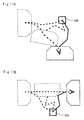
- FIGs. 12 and 13 are diagrams showing conventional transfer robots.
- Figs. 12 and 13 show a vertical articulated robot and a horizontal articulated robot, respectively.
- a vertical articulated robot 200 includes a base 201 that is fixed to a floor surface, a supporting section 202 that is attached to the base 201 through a link mechanism (not shown), a first arm 204 that is rotatably attached to the supporting section 202 by a link mechanism 203 in a vertical direction, a second arm that is rotatably attached to the first arm 204 by a link mechanism 205 in a vertical direction, a holding section 208 that is rotatably attached to the second arm by a link mechanism 207 in a vertical direction, and a pin 209 that is attached to the holding section 208.
- Rotation of the link mechanisms 203, 205, and 207 moves the first arm 204, the second arm 206, and the holding section 208 in a vertical direction. Further, the supporting section 202 is rotated in a horizontal direction by a link mechanism that is provided between the base 201 and the supporting section 202.
- a horizontal articulated robot 300 includes a base 301 that is fixed to a floor surface, a link mechanism 302 that is attached to the base 301, a first arm 303 that is rotatably attached by the link mechanism 302 in a horizontal direction, a second arm 306 that is rotatably attached to the first arm 303 by a link mechanism 305 in a horizontal direction, a hose 304 including an electric line that is connected to the second arm 306, and a cylinder 307 that is provided in the second arm 306 and moves up and down in a vertical direction. Rotation of the link mechanisms 302, 305 moves the first arm 303 and the second arm 306 in a horizontal direction.
- a transfer robot that transfers a transfer object in a horizontal direction is known to the public.
- a carriage that is employed in a manufacturing line such as an assembly line weighs 50 to 300 kg.
- the work man-hour increases as the carriage needs to be maneuvered to a large number of places.
- a labor cost that is spent for maneuvering a carriage is extremely high.
- a large-scale arm having a high-output motor is required in transferring the transfer object by lifting it.
- a robot which transfers such a carriage or the like, having extremely large operating area and high output includes a high-output motor, which requires execution of security measures such as a fence, occupies large space due to its large size, and even leads to process division or degradation of line prediction. Further, an equipment cost is extremely high.
- JP-A-06 143 162 discloses an industrial robot with a telescopic arm rotatable in a horizontal plane and comprising support legs with wheels to follow the longitudinal extension of the arm sections.
- the present invention provides a transfer robot as defined in claim 1.
- deadweight of the robot is supported by attaching the caster to the lower surface of the first arm and rotating the arm in a horizontal plane by the link mechanism, whereby a motor having lower output may be employed.
- the transfer robot may include one or a plurality of second arms attached to a position between the base and the first arm by a link mechanism so as to rotate in a horizontal direction. By inserting one or a plurality of second arms, transfer range of the robot can be arbitrarily set.
- the transfer robot may further include a caster that is attached to a lower surface of the second arm, the caster supporting deadweight of the second arm.
- the link mechanism in the base side has a higher gear ratio of the second reduction mechanism to the first reduction mechanism than the link mechanism in the first arm side.
- the gear ratio in the base side can be made larger in accordance with it.
- the holding section may include a pin that fits a held section provided in the transfer object, and is able to transfer the transfer object by fixing it with the pin.
- the holding section includes a cylinder that holds the pin, and the pin is configured to be movable in a direction that is apart from the first arm, which is a vertical or a horizontal direction, for example.
- the position of the holding section may vary according to the height of the transfer object or the like.
- FIGs. 1 to 3 respectively show a perspective view, a side view, and a plane view showing a transfer robot according to the embodiment of the present invention.
- a transfer robot 100 according to the present embodiment includes a base section 1, link sections 2a, 2b, a distal end link section 3, and a holding section 4.
- the base section 1 is fixed to a floor surface, and a carriage 13 is held by the holding section 4 provided in the distal end link section 3. Then, each rotation of the link sections 2a, 2b and the distal end link section 3 in a horizontal direction moves the carriage 13 in a horizontal direction.
- Figs. 4 to 7 are perspective views showing the base section 1, the link section 2a, the distal end link section 3, and the holding section 4, respectively.
- the base section 1 includes, as shown in Fig. 4 , a motor 5a, a first reduction mechanism 6a that is attached to a distal end of the motor 5a and rotated about a vertical axis by the motor 5a, and a base 7 to which the first reduction mechanism 6a is attached.
- the transfer robot 100 according to the present embodiment is configured to move only in a two-dimensional manner, to thereby reduce the load of the motor 5a.
- the motor 5a with low output as 80 W or lower may be employed.
- the link section 2a includes, as shown in Fig. 5 , a second reduction mechanism 8b that is coupled to the first reduction mechanism 6a of the base section 1, an arm 9b as a second arm where the second reduction mechanism 8b is attached to its one end of the upper surface, a motor 5b, a first reduction mechanism 6b rotated by the motor 5b and provided in the other end of the arm 9b, and a caster 10b that is attached to a lower surface of the arm 9b to support and move the arm 9b.
- the first reduction mechanism and the second reduction mechanism are mechanisms that reduce rotation of the motor by combining a reducer, a gearbox, a gear wheel and so on.
- the second reduction mechanism 8b also rotates in a horizontal direction about the vertical axis similarly to the first reduction mechanism 6a.
- the link mechanism is formed by the motor 5a, the first reduction mechanism 6a, and the second reduction mechanism 8b.
- the first reduction mechanism 6a of the base section 1 is rotated by the motor 5a, and thus the second reduction mechanism 8b that is coupled to the first reduction mechanism 6a is rotated.
- the first reduction mechanism 6a and the second reduction mechanism 8b are configured in a way that both gear wheels mesh together.
- the rotation of the second reduction mechanism 8b rotates the arm 9b in a horizontal direction.
- the link section 2b is formed similarly to the link section 2a.
- the distal end link section 3 includes, as shown in Fig. 6 , a second reduction mechanism 8d, an arm 9d as a first arm where the second reduction mechanism 8d is attached to its one end of the upper surface, a motor 5d, a first reduction mechanism 6d rotated by the motor 5d, and a caster 10d that is attached to the lower surface of the arm 9d to support and move the arm 9d.
- the distal end link section 3 includes the holding section 4 that is connected to the first reduction mechanism 6d.
- the holding section 4 includes, as shown in Fig. 7 , a second reduction mechanism 8e that is coupled to the first reduction mechanism 6d, a cylinder 11 that is rotated by the second reduction mechanism 8e, a supporting section 12c having a flat plate shape that moves up and down in a vertical direction by the cylinder 11, and pins 12a and 12b being respectively provided in one of two ends of the supporting section 12c.
- the first reduction mechanism 6d is rotated by the motor 5d, and thus, the second reduction mechanism 8e is rotated. Then, the rotation of the cylinder 11 attached to the second reduction mechanism 8e changes the positions of the pins 12a and 12b.
- the pins 12a and 12b are described to move in a vertical direction by the cylinder 11 in the holding section 4 in the present embodiment, the pins 12a and 12b may be adapted to move in a horizontal direction by the cylinder 11. Alternatively, the pins 12a and 12b may be configured to move in any direction to be apart from the distal end link section 3 depending on the method of attaching the cylinder 11, not only in the horizontal direction or the vertical direction.
- each gear ratio of the second reduction mechanisms 8b to 8e to the first reduction mechanisms 6a to 6d in each axis is formed to be higher as approaching the base section 1 side.
- the gear ratio of the second reduction mechanism 8b to the first reduction mechanism 6a is larger than that of the second reduction mechanism 8c to the first reduction mechanism 6b
- the gear ratio of the second reduction mechanism 8c to the first reduction mechanism 6b is larger than that of the second reduction mechanism 8d to the first reduction mechanism 6c.
- Figs. 8A and 8B are plane views respectively showing a first state and a second state in which the motors of the transfer robot are driven and each joint (link mechanism) is bent.
- Fig. 8A shows a state in which the motor 5a of the base section 1 is driven and the first reduction mechanism 6a and the second reduction mechanism 8b are rotated.
- Fig. 8B shows a state in which the motors 5b and 5c are driven further from the state shown in Fig. 8A to rotate the first reduction mechanisms 6b, 6c and the second reduction mechanisms 8c, 8d.
- Each of the motors 5a to 5d includes an encoder therein, and controls an angle of each joint when the angle is given. Note that, in the present embodiment, a straight-line state as shown in Fig. 2 corresponds to zero degree of the encoder.
- Fig. 9 is a diagram showing the carriage as the transfer object and the holding section.
- the carriage 13 includes held sections 14a and 14b that incorporate the pins 12a and 12b of the holding section 4.
- the carriage 13 is configured to be able to carry a load and move on a floor surface with a body 13a and four casters 13b that support and move the body 13a.
- the carriage 13 is fixed by inserting the pins 12a and 12b of the holding section 4 into the held sections 14a and 14b of the carriage 13.
- Figs. 10 , 11A, and 11B each shows an operation example of the transfer robot.
- the transfer robot 100 moves the carriage from a position 15 to a position 17.
- the transfer robot 100 approaches the position 15 while storing the pins 12a and 12b, and inserts the pins 12a and 12b of the holding section 4 into the held sections 14a and 14b of the carriage 13 in a fixed position, so as to fix the carriage 13.
- the transfer robot 100 moves toward the position 16 while controlling the angle and the speed by the motors 5a to 5d of each joint (link mechanism), and then to the position 17.
- the transfer robot 100 stores the pins 12a and 12b and separates the carriage 13.
- the robot 100 again approaches the position 15 in order to transfer the next carriage, and repeats the aforementioned operation.
- the operations shown in Figs. 11A and 11B are similar.
- a conventional transfer robot holds a deadweight and a weight of a transfer object with a motor. As the transfer object is designed to be carried with being lifted, the robot itself needs to be rigid. This leads to increase of the deadweight.
- the transferring is limited to flat transferring without lifting the transfer object, to thereby reducing the load required for transferring and making the operation of the robot two-dimensional.
- the deadweight is supported by the casters in order to reduce the motor load by the deadweight.
- the outputs of the motors 5a to 5d may be lowered to the extent that does not require any safety measures: 80 W, for example.
- the gear ratio of the second reduction mechanism to the first reduction mechanism is made larger as approaching the base section 1 side, whereby it is possible to withstand the load torque which is larger in the base section 1 side.
- a low-output motor essentially safe configuration can be obtained, and the transfer robot may be introduced in a process where a worker is also involved. Further, transfer of a carriage or the like can be automated without wasting the space or impairing a line prediction or the like. Moreover, as transfer tracks can be arbitrarily set, it is possible to transfer a carriage in a way that does not interfere with a work traffic line in a process where the worker is also involved. Further, carriage transfer position can be readily changed only by changing teach points that indicates a start point, an end point, and a passing point of the operation. Furthermore, as the installation is completed only by fixing the base section 1 to the floor surface, installation works, process change or the like may be performed without holiday works or long-term works.
- the transfer robot may be composed of the base section 1 and the distal end link section 3 without providing any link section.
- one link section or three or more link sections may be provided.
- the robot may be supported by the base section and the distal end link section depending on the lengths of the arm of the link section. In such a case, the caster of the link section need not be arranged.
- the present invention is applicable to transfer robots to transfer a transfer object such as a carriage on the plane surface without lifting it.
Abstract
Description
- The present invention relates to a transfer robot to transfer a transfer object such as a carriage on a plane surface without lifting it.
-
Figs. 12 and 13 are diagrams showing conventional transfer robots.Figs. 12 and 13 show a vertical articulated robot and a horizontal articulated robot, respectively. A vertical articulatedrobot 200 includes abase 201 that is fixed to a floor surface, a supportingsection 202 that is attached to thebase 201 through a link mechanism (not shown), afirst arm 204 that is rotatably attached to the supportingsection 202 by alink mechanism 203 in a vertical direction, a second arm that is rotatably attached to thefirst arm 204 by alink mechanism 205 in a vertical direction, aholding section 208 that is rotatably attached to the second arm by alink mechanism 207 in a vertical direction, and apin 209 that is attached to theholding section 208. Rotation of thelink mechanisms first arm 204, thesecond arm 206, and theholding section 208 in a vertical direction. Further, the supportingsection 202 is rotated in a horizontal direction by a link mechanism that is provided between thebase 201 and the supportingsection 202. - Further, a horizontal articulated
robot 300 includes abase 301 that is fixed to a floor surface, alink mechanism 302 that is attached to thebase 301, afirst arm 303 that is rotatably attached by thelink mechanism 302 in a horizontal direction, asecond arm 306 that is rotatably attached to thefirst arm 303 by alink mechanism 305 in a horizontal direction, ahose 304 including an electric line that is connected to thesecond arm 306, and acylinder 307 that is provided in thesecond arm 306 and moves up and down in a vertical direction. Rotation of thelink mechanisms first arm 303 and thesecond arm 306 in a horizontal direction. As such a transfer robot that transfers a transfer object in a horizontal direction is known to the public. - However, when a transfer object is transferred by being lifted with the conventional robot that transfers the transfer object, a large-scale arm with a high-output motor is required. However, in a case of the transfer object such as a carriage that moves on a plane surface, the carriage needs to be maneuvered to a great number of places, and thus, it is needed to form a robot having high power and extremely wide operating area for transferring these transfer objects.
- For example, a carriage that is employed in a manufacturing line such as an assembly line weighs 50 to 300 kg. When a worker transfers the carriage instead of using a robot, the work man-hour increases as the carriage needs to be maneuvered to a large number of places. In short, a labor cost that is spent for maneuvering a carriage is extremely high. On the other hand, in the conventional transfer robot that transfers such a carriage or the like, a large-scale arm having a high-output motor is required in transferring the transfer object by lifting it. However, a robot, which transfers such a carriage or the like, having extremely large operating area and high output includes a high-output motor, which requires execution of security measures such as a fence, occupies large space due to its large size, and even leads to process division or degradation of line prediction. Further, an equipment cost is extremely high.
- The present invention has been made in order to solve such problems, and it is one object of the present invention to provide a transfer robot that is safe and produced at low cost.
JP-A-06 143 162 - Accordingly, the present invention provides a transfer robot as defined in
claim 1. - According to the present invention, as the transfer object is transferred, deadweight of the robot is supported by attaching the caster to the lower surface of the first arm and rotating the arm in a horizontal plane by the link mechanism, whereby a motor having lower output may be employed.
- Further, the transfer robot may include one or a plurality of second arms attached to a position between the base and the first arm by a link mechanism so as to rotate in a horizontal direction. By inserting one or a plurality of second arms, transfer range of the robot can be arbitrarily set.
- Furthermore, the transfer robot may further include a caster that is attached to a lower surface of the second arm, the caster supporting deadweight of the second arm.
- Furthermore, the link mechanism in the base side has a higher gear ratio of the second reduction mechanism to the first reduction mechanism than the link mechanism in the first arm side. As a load torque in the base side is larger, the gear ratio in the base side can be made larger in accordance with it.
- Further, the holding section may include a pin that fits a held section provided in the transfer object, and is able to transfer the transfer object by fixing it with the pin.
- Furthermore, the holding section includes a cylinder that holds the pin, and the pin is configured to be movable in a direction that is apart from the first arm, which is a vertical or a horizontal direction, for example. The position of the holding section may vary according to the height of the transfer object or the like.
- According to the present invention, it is possible to provide a transfer robot that is safe and produced at low cost.
-
-
Fig. 1 is a perspective view showing a transfer robot according to an embodiment of the present invention; -
Fig. 2 is a side view showing the transfer robot according to the embodiment of the present invention; -
Fig. 3 is a plane view showing the transfer robot according to the embodiment of the present invention; -
Fig. 4 is a perspective view showing a base section in the transfer robot according to the embodiment of the present invention; -
Fig. 5 is a perspective view showing alink section 2a in the transfer robot according to the embodiment of the present invention; -
Fig. 6 is a perspective view showing a distalend link section 3 in the transfer robot according to the embodiment of the present invention; -
Fig. 7 is a perspective view showing aholding section 4 in the transfer robot according to the embodiment of the present invention; -
Fig. 8A is a plane view showing a first state in which a motor of the transfer robot is driven and each joint (link mechanism) is bent according to the embodiment of the present invention; -
Fig. 8B is a plane view showing a second state in which a motor of the transfer robot is driven and each joint (link mechanism) is bent according to the embodiment of the present invention; -
Fig. 9 is a diagram showing a carriage as a transfer object and a holding section in the transfer robot according to the embodiment of the present invention; -
Fig. 10 is a diagram showing an operation example of the transfer robot according to the embodiment of the present invention; -
Fig. 11A is a diagram showing an operation example of the transfer robot according to the embodiment of the present invention; -
Fig. 11B is a diagram showing an operation example of the transfer robot according to the embodiment of the present invention; -
Fig. 12 is a diagram showing a conventional vertical articulated transfer robot; and -
Fig. 13 is a diagram showing a conventional horizontal articulated transfer robot. -
- 2a, 2b
- LINK SECTION
- 3
- DISTAL END LINK SECTION
- 4
- HOLDING SECTION
- 5a~5d
- MOTOR
- 6a~6d
- FIRST REDUCTION MECHANISM
- 7
- BASE
- 8b~8e
- SECOND REDUCTION MECHANISM
- 9b~9d
- ARM
- 10b~10d, 13b
- CASTER
- 11
- CYLINDER
- 12a, 12b
- PIN
- 12c
- SUPPORTING SECTION
- 13
- CARRIAGE
- 13a
- BODY
- 14a, 14b
- HELD SECTION
- 15, 16, 17
- POSITION
- 100
- TRANSFER ROBOT
- Hereinafter, the specific embodiment to which the present invention is applied will be described in detail with reference to the drawings.
Figs. 1 to 3 respectively show a perspective view, a side view, and a plane view showing a transfer robot according to the embodiment of the present invention. Atransfer robot 100 according to the present embodiment includes abase section 1,link sections end link section 3, and aholding section 4. Thebase section 1 is fixed to a floor surface, and acarriage 13 is held by the holdingsection 4 provided in the distalend link section 3. Then, each rotation of thelink sections end link section 3 in a horizontal direction moves thecarriage 13 in a horizontal direction. -
Figs. 4 to 7 are perspective views showing thebase section 1, thelink section 2a, the distalend link section 3, and theholding section 4, respectively. Thebase section 1 includes, as shown inFig. 4 , amotor 5a, afirst reduction mechanism 6a that is attached to a distal end of themotor 5a and rotated about a vertical axis by themotor 5a, and abase 7 to which thefirst reduction mechanism 6a is attached. Thetransfer robot 100 according to the present embodiment is configured to move only in a two-dimensional manner, to thereby reduce the load of themotor 5a. For example, themotor 5a with low output as 80 W or lower may be employed. - The
link section 2a includes, as shown inFig. 5 , asecond reduction mechanism 8b that is coupled to thefirst reduction mechanism 6a of thebase section 1, anarm 9b as a second arm where thesecond reduction mechanism 8b is attached to its one end of the upper surface, amotor 5b, afirst reduction mechanism 6b rotated by themotor 5b and provided in the other end of thearm 9b, and acaster 10b that is attached to a lower surface of thearm 9b to support and move thearm 9b. The first reduction mechanism and the second reduction mechanism are mechanisms that reduce rotation of the motor by combining a reducer, a gearbox, a gear wheel and so on. Thesecond reduction mechanism 8b also rotates in a horizontal direction about the vertical axis similarly to thefirst reduction mechanism 6a. The link mechanism is formed by themotor 5a, thefirst reduction mechanism 6a, and thesecond reduction mechanism 8b. - The
first reduction mechanism 6a of thebase section 1 is rotated by themotor 5a, and thus thesecond reduction mechanism 8b that is coupled to thefirst reduction mechanism 6a is rotated. Although not shown inFigs. 4 to 7 , thefirst reduction mechanism 6a and thesecond reduction mechanism 8b are configured in a way that both gear wheels mesh together. The rotation of thesecond reduction mechanism 8b rotates thearm 9b in a horizontal direction. Thelink section 2b is formed similarly to thelink section 2a. - The distal
end link section 3 includes, as shown inFig. 6 , asecond reduction mechanism 8d, anarm 9d as a first arm where thesecond reduction mechanism 8d is attached to its one end of the upper surface, amotor 5d, afirst reduction mechanism 6d rotated by themotor 5d, and acaster 10d that is attached to the lower surface of thearm 9d to support and move thearm 9d. The distalend link section 3 includes the holdingsection 4 that is connected to thefirst reduction mechanism 6d. - The holding
section 4 includes, as shown inFig. 7 , asecond reduction mechanism 8e that is coupled to thefirst reduction mechanism 6d, acylinder 11 that is rotated by thesecond reduction mechanism 8e, a supportingsection 12c having a flat plate shape that moves up and down in a vertical direction by thecylinder 11, and pins 12a and 12b being respectively provided in one of two ends of the supportingsection 12c. Thefirst reduction mechanism 6d is rotated by themotor 5d, and thus, thesecond reduction mechanism 8e is rotated. Then, the rotation of thecylinder 11 attached to thesecond reduction mechanism 8e changes the positions of thepins pins cylinder 11 in theholding section 4 in the present embodiment, thepins cylinder 11. Alternatively, thepins end link section 3 depending on the method of attaching thecylinder 11, not only in the horizontal direction or the vertical direction. - Now, the load torque increases as approaching a base side, or the
base section 1 side. Accordingly, each gear ratio of thesecond reduction mechanisms 8b to 8e to thefirst reduction mechanisms 6a to 6d in each axis is formed to be higher as approaching thebase section 1 side. In summary, the gear ratio of thesecond reduction mechanism 8b to thefirst reduction mechanism 6a is larger than that of thesecond reduction mechanism 8c to thefirst reduction mechanism 6b, and the gear ratio of thesecond reduction mechanism 8c to thefirst reduction mechanism 6b is larger than that of thesecond reduction mechanism 8d to thefirst reduction mechanism 6c. -
Figs. 8A and 8B are plane views respectively showing a first state and a second state in which the motors of the transfer robot are driven and each joint (link mechanism) is bent.Fig. 8A shows a state in which themotor 5a of thebase section 1 is driven and thefirst reduction mechanism 6a and thesecond reduction mechanism 8b are rotated.Fig. 8B shows a state in which themotors Fig. 8A to rotate thefirst reduction mechanisms second reduction mechanisms motors 5a to 5d includes an encoder therein, and controls an angle of each joint when the angle is given. Note that, in the present embodiment, a straight-line state as shown inFig. 2 corresponds to zero degree of the encoder. -
Fig. 9 is a diagram showing the carriage as the transfer object and the holding section. As shown inFig. 9 , thecarriage 13 includes heldsections pins section 4. Thecarriage 13 is configured to be able to carry a load and move on a floor surface with abody 13a and fourcasters 13b that support and move thebody 13a. Thecarriage 13 is fixed by inserting thepins section 4 into the heldsections carriage 13. -
Figs. 10 ,11A, and 11B each shows an operation example of the transfer robot. As shown inFig. 10 , thetransfer robot 100 moves the carriage from aposition 15 to aposition 17. First, thetransfer robot 100 approaches theposition 15 while storing thepins pins section 4 into the heldsections carriage 13 in a fixed position, so as to fix thecarriage 13. - The
transfer robot 100 moves toward theposition 16 while controlling the angle and the speed by themotors 5a to 5d of each joint (link mechanism), and then to theposition 17. When arriving at theposition 17, thetransfer robot 100 stores thepins carriage 13. Then, therobot 100 again approaches theposition 15 in order to transfer the next carriage, and repeats the aforementioned operation. The operations shown inFigs. 11A and 11B are similar. - A conventional transfer robot holds a deadweight and a weight of a transfer object with a motor. As the transfer object is designed to be carried with being lifted, the robot itself needs to be rigid. This leads to increase of the deadweight.
- On the other hand, in the present embodiment, the transferring is limited to flat transferring without lifting the transfer object, to thereby reducing the load required for transferring and making the operation of the robot two-dimensional. Further, the deadweight is supported by the casters in order to reduce the motor load by the deadweight. As such, the outputs of the
motors 5a to 5d may be lowered to the extent that does not require any safety measures: 80 W, for example. Further, as the gear ratio of the second reduction mechanism to the first reduction mechanism is made larger as approaching thebase section 1 side, whereby it is possible to withstand the load torque which is larger in thebase section 1 side. - Further, as it is possible to employ a low-output motor, essentially safe configuration can be obtained, and the transfer robot may be introduced in a process where a worker is also involved. Further, transfer of a carriage or the like can be automated without wasting the space or impairing a line prediction or the like. Moreover, as transfer tracks can be arbitrarily set, it is possible to transfer a carriage in a way that does not interfere with a work traffic line in a process where the worker is also involved. Further, carriage transfer position can be readily changed only by changing teach points that indicates a start point, an end point, and a passing point of the operation. Furthermore, as the installation is completed only by fixing the
base section 1 to the floor surface, installation works, process change or the like may be performed without holiday works or long-term works. - Needless to say, the present invention is not limited to the above embodiment, but various modifications can be made without departing from the scope of the present invention. For example, although the two
link sections base section 1 and the distalend link section 3 without providing any link section. Alternatively, one link section or three or more link sections may be provided. Further alternatively, the robot may be supported by the base section and the distal end link section depending on the lengths of the arm of the link section. In such a case, the caster of the link section need not be arranged. - The present invention is applicable to transfer robots to transfer a transfer object such as a carriage on the plane surface without lifting it.
Claims (7)
- A transfer robot (100) comprising:a base (7);a link mechanism that is provided on the base (7);a first arm (9d) that is attached to the base (7) by the link mechanism so as to rotate in a horizontal plane;a caster (10d) attached to a lower surface of the first arm (9d) and used to support and move the first arm (2a) around the link mechanism;a holding section (4) provided on an upper surface of the first arm (9d); anda carriage (13) held by the holding section (4) without lifting and transferred in a plane, whereinthe link mechanism comprises a motor (5c), a first reduction mechanism (6c) that controls rotation by the motor (5c), and a second reduction mechanism (8d) that is coupled to the first reduction mechanism (6c) and controls rotation of the first arm (9d).
- The transfer robot (100) according to Claim 1, comprising one or a plurality of second arms (9b, 9c) that are attached between the base (7) and the first arm (9d) by a link mechanism so as to rotate in a horizontal plane.
- The transfer robot (100) according to Claim 2, further comprising a caster (10b, 10c) that is attached to a lower surface of the second arm (9b, 9c).
- The transfer robot (100) according to Claim 2 or 3, wherein the link mechanism in the base (7) side has a higher gear ratio of the second reduction mechanism (8b) to the first reduction mechanism (6a) than the link mechanism in the first arm (9d) side.
- The transfer robot (100) according to any one of Claims 1 to 4, wherein the holding section (4) comprises a pin (12a, 12b) that fits a held section (14a, 14b) provided in the carriage (13).
- The transfer robot (100) according to Claim 5, wherein the holding section (4) further comprises a cylinder (11) that holds the pin (12a, 12b), and the pin (12a, 12b) is configured to be movable in a direction that is apart from the first arm (9d).
- The transfer robot (100) according to Claim 6, wherein the pin (12a, 12b) is configured to be movable in a horizontal or a vertical direction.
Applications Claiming Priority (2)
| Application Number | Priority Date | Filing Date | Title |
|---|---|---|---|
| JP2007070057A JP4737123B2 (en) | 2007-03-19 | 2007-03-19 | Transfer robot |
| PCT/JP2008/054228 WO2008114630A1 (en) | 2007-03-19 | 2008-03-03 | Transfer robot |
Publications (3)
| Publication Number | Publication Date |
|---|---|
| EP2147756A1 EP2147756A1 (en) | 2010-01-27 |
| EP2147756A4 EP2147756A4 (en) | 2011-06-22 |
| EP2147756B1 true EP2147756B1 (en) | 2012-04-25 |
Family
ID=39765739
Family Applications (1)
| Application Number | Title | Priority Date | Filing Date |
|---|---|---|---|
| EP08721645A Not-in-force EP2147756B1 (en) | 2007-03-19 | 2008-03-03 | Transfer robot |
Country Status (7)
| Country | Link |
|---|---|
| US (1) | US8096380B2 (en) |
| EP (1) | EP2147756B1 (en) |
| JP (1) | JP4737123B2 (en) |
| CN (1) | CN101631650B (en) |
| AT (1) | ATE554887T1 (en) |
| CA (1) | CA2680001C (en) |
| WO (1) | WO2008114630A1 (en) |
Families Citing this family (11)
| Publication number | Priority date | Publication date | Assignee | Title |
|---|---|---|---|---|
| JP4770856B2 (en) * | 2008-03-21 | 2011-09-14 | トヨタ自動車株式会社 | Transfer robot |
| JP5228784B2 (en) * | 2008-10-15 | 2013-07-03 | 株式会社Ihi | Manipulator system |
| JP2010287745A (en) * | 2009-06-11 | 2010-12-24 | Tokyo Electron Ltd | Transfer module |
| USD625748S1 (en) * | 2010-05-06 | 2010-10-19 | Ulvac, Inc. | Vacuum transfer robot |
| USRE44567E1 (en) * | 2009-11-17 | 2013-11-05 | Ulvac, Inc. | Vacuum transfer robot |
| USD639323S1 (en) * | 2010-05-06 | 2011-06-07 | Ulvac, Inc. | Vacuum transfer robot |
| USRE43781E1 (en) * | 2009-11-17 | 2012-11-06 | Ulvac, Inc. | Vacuum transfer robot |
| JP5408212B2 (en) | 2011-09-07 | 2014-02-05 | 株式会社安川電機 | Working robot and processing equipment |
| JP7015123B2 (en) * | 2016-07-26 | 2022-02-02 | 清水建設株式会社 | Handling robot and how to use it |
| EP3600787A4 (en) * | 2017-03-26 | 2021-01-13 | Genesis Robotics and Motion Technologies Canada, ULC | Robot arm |
| USD997223S1 (en) * | 2023-06-07 | 2023-08-29 | Primate Robot Hong Kong Co., Limited | Robot |
Family Cites Families (18)
| Publication number | Priority date | Publication date | Assignee | Title |
|---|---|---|---|---|
| JPS60127931A (en) * | 1983-12-15 | 1985-07-08 | Mitsubishi Electric Corp | Industrial robot device |
| US4764077A (en) * | 1986-04-18 | 1988-08-16 | Thermwood Corporation | Assembly for performing work functions on a workpiece |
| US4993896A (en) * | 1988-12-13 | 1991-02-19 | General Electric Company | Edge contouring system |
| JPH0756040B2 (en) | 1989-09-29 | 1995-06-14 | 花王株式会社 | Residential hard surface liquid detergent composition |
| US5271686A (en) * | 1992-01-27 | 1993-12-21 | The Budd Company | Robot hand for aligning and isolating a work tool |
| JP2648271B2 (en) * | 1992-11-09 | 1997-08-27 | 日立造船株式会社 | Workbench for box-type block |
| CN2196537Y (en) * | 1994-05-18 | 1995-05-10 | 吉林江北机械厂 | Rod-type machine hand |
| JPH08118267A (en) | 1994-10-18 | 1996-05-14 | M Alpha Giken:Kk | Conveyer robot |
| JP3077564B2 (en) * | 1995-06-09 | 2000-08-14 | 澁谷工業株式会社 | Article processing equipment |
| JP2699941B2 (en) * | 1995-07-20 | 1998-01-19 | 日本電気株式会社 | Robot joints |
| US6554991B1 (en) * | 1997-06-24 | 2003-04-29 | Large Scale Proteomics Corporation | Automated system for two-dimensional electrophoresis |
| JPH1133949A (en) * | 1997-07-14 | 1999-02-09 | Fanuc Ltd | Industrial robot |
| AU2612500A (en) * | 1999-01-15 | 2000-08-01 | Asyst Technologies, Inc. | Workpiece handling robot |
| JP4558981B2 (en) * | 2000-11-14 | 2010-10-06 | 株式会社ダイヘン | Transfer robot |
| JP3883535B2 (en) * | 2003-10-28 | 2007-02-21 | ファナック株式会社 | Robot transport auxiliary equipment |
| JP2006167864A (en) * | 2004-12-16 | 2006-06-29 | Seiko Epson Corp | Horizontal articulated robot |
| JP4606388B2 (en) * | 2006-06-12 | 2011-01-05 | 川崎重工業株式会社 | Transfer system unit for substrate transfer equipment |
| JP5428131B2 (en) * | 2007-02-09 | 2014-02-26 | 富士通株式会社 | Observation device and void observation method |
-
2007
- 2007-03-19 JP JP2007070057A patent/JP4737123B2/en not_active Expired - Fee Related
-
2008
- 2008-03-03 US US12/530,858 patent/US8096380B2/en not_active Expired - Fee Related
- 2008-03-03 CA CA2680001A patent/CA2680001C/en not_active Expired - Fee Related
- 2008-03-03 WO PCT/JP2008/054228 patent/WO2008114630A1/en active Application Filing
- 2008-03-03 AT AT08721645T patent/ATE554887T1/en active
- 2008-03-03 EP EP08721645A patent/EP2147756B1/en not_active Not-in-force
- 2008-03-03 CN CN200880007916.2A patent/CN101631650B/en not_active Expired - Fee Related
Also Published As
| Publication number | Publication date |
|---|---|
| US20100101357A1 (en) | 2010-04-29 |
| WO2008114630A1 (en) | 2008-09-25 |
| EP2147756A4 (en) | 2011-06-22 |
| CN101631650A (en) | 2010-01-20 |
| JP2008230327A (en) | 2008-10-02 |
| EP2147756A1 (en) | 2010-01-27 |
| CA2680001A1 (en) | 2008-09-25 |
| CA2680001C (en) | 2012-01-10 |
| ATE554887T1 (en) | 2012-05-15 |
| CN101631650B (en) | 2011-09-07 |
| JP4737123B2 (en) | 2011-07-27 |
| US8096380B2 (en) | 2012-01-17 |
Similar Documents
| Publication | Publication Date | Title |
|---|---|---|
| EP2147756B1 (en) | Transfer robot | |
| US7971504B2 (en) | Articulated manipulator | |
| US8231117B2 (en) | Robot system | |
| US9409269B2 (en) | Positioning apparatus, working system, and hot working apparatus | |
| CN109131624B (en) | Multi-degree-of-freedom obstacle-surmounting pole-climbing device | |
| CN105666463A (en) | Tail end tool hand and gripper rapid disassembling and assembling system under nuclear radiation environment | |
| CN111119500A (en) | Wall building machine | |
| EP3867018A1 (en) | Tool robot for use in construction | |
| CN213499286U (en) | High-load type mechanical arm with large operation radius | |
| CN113459068A (en) | Mechanical arm for space station load on-orbit maintenance | |
| CN101977736A (en) | Clamping device and transfer robot | |
| CN211572658U (en) | Wall building machine | |
| CN112706809A (en) | Four-freedom-degree accurate hoisting carrier loader for lower parts of motor train unit | |
| CN107571245B (en) | Small-size handling machine of 6 degrees of freedom parallel mechanism of numerical control | |
| CN106903495A (en) | A kind of robot mechanism that assembly manipulation is directed at for heavy parts | |
| JPH0641119B2 (en) | Manipulator | |
| CN110562688A (en) | quick switching system of positioning fixture | |
| CN215393295U (en) | Robot unilateral overturning welding workstation for hydraulic support structural part | |
| JPH07328963A (en) | Heavy article manipulator device, heavy article manipulator facility, and control method thereof | |
| KR20130073573A (en) | Lifting lug handling apparatus | |
| RU218445U1 (en) | Power manipulator | |
| CN214724215U (en) | Six-axis column coordinate industrial robot | |
| CN215471105U (en) | Mechanical arm for space station load on-track maintenance | |
| CN209319794U (en) | A kind of five axis all positon cutting robots | |
| JP3174326U (en) | Horizontal articulated conveyor |
Legal Events
| Date | Code | Title | Description |
|---|---|---|---|
| PUAI | Public reference made under article 153(3) epc to a published international application that has entered the european phase |
Free format text: ORIGINAL CODE: 0009012 |
|
| 17P | Request for examination filed |
Effective date: 20091009 |
|
| AK | Designated contracting states |
Kind code of ref document: A1 Designated state(s): AT BE BG CH CY CZ DE DK EE ES FI FR GB GR HR HU IE IS IT LI LT LU LV MC MT NL NO PL PT RO SE SI SK TR |
|
| AX | Request for extension of the european patent |
Extension state: AL BA MK RS |
|
| DAX | Request for extension of the european patent (deleted) | ||
| A4 | Supplementary search report drawn up and despatched |
Effective date: 20110525 |
|
| GRAP | Despatch of communication of intention to grant a patent |
Free format text: ORIGINAL CODE: EPIDOSNIGR1 |
|
| GRAS | Grant fee paid |
Free format text: ORIGINAL CODE: EPIDOSNIGR3 |
|
| GRAA | (expected) grant |
Free format text: ORIGINAL CODE: 0009210 |
|
| AK | Designated contracting states |
Kind code of ref document: B1 Designated state(s): AT BE BG CH CY CZ DE DK EE ES FI FR GB GR HR HU IE IS IT LI LT LU LV MC MT NL NO PL PT RO SE SI SK TR |
|
| REG | Reference to a national code |
Ref country code: GB Ref legal event code: FG4D |
|
| REG | Reference to a national code |
Ref country code: CH Ref legal event code: EP |
|
| REG | Reference to a national code |
Ref country code: AT Ref legal event code: REF Ref document number: 554887 Country of ref document: AT Kind code of ref document: T Effective date: 20120515 |
|
| REG | Reference to a national code |
Ref country code: IE Ref legal event code: FG4D |
|
| REG | Reference to a national code |
Ref country code: DE Ref legal event code: R096 Ref document number: 602008015186 Country of ref document: DE Effective date: 20120705 |
|
| REG | Reference to a national code |
Ref country code: NL Ref legal event code: VDEP Effective date: 20120425 |
|
| REG | Reference to a national code |
Ref country code: AT Ref legal event code: MK05 Ref document number: 554887 Country of ref document: AT Kind code of ref document: T Effective date: 20120425 |
|
| LTIE | Lt: invalidation of european patent or patent extension |
Effective date: 20120425 |
|
| PG25 | Lapsed in a contracting state [announced via postgrant information from national office to epo] |
Ref country code: CY Free format text: LAPSE BECAUSE OF FAILURE TO SUBMIT A TRANSLATION OF THE DESCRIPTION OR TO PAY THE FEE WITHIN THE PRESCRIBED TIME-LIMIT Effective date: 20120425 Ref country code: NO Free format text: LAPSE BECAUSE OF FAILURE TO SUBMIT A TRANSLATION OF THE DESCRIPTION OR TO PAY THE FEE WITHIN THE PRESCRIBED TIME-LIMIT Effective date: 20120725 Ref country code: FI Free format text: LAPSE BECAUSE OF FAILURE TO SUBMIT A TRANSLATION OF THE DESCRIPTION OR TO PAY THE FEE WITHIN THE PRESCRIBED TIME-LIMIT Effective date: 20120425 Ref country code: LT Free format text: LAPSE BECAUSE OF FAILURE TO SUBMIT A TRANSLATION OF THE DESCRIPTION OR TO PAY THE FEE WITHIN THE PRESCRIBED TIME-LIMIT Effective date: 20120425 Ref country code: IS Free format text: LAPSE BECAUSE OF FAILURE TO SUBMIT A TRANSLATION OF THE DESCRIPTION OR TO PAY THE FEE WITHIN THE PRESCRIBED TIME-LIMIT Effective date: 20120825 Ref country code: SE Free format text: LAPSE BECAUSE OF FAILURE TO SUBMIT A TRANSLATION OF THE DESCRIPTION OR TO PAY THE FEE WITHIN THE PRESCRIBED TIME-LIMIT Effective date: 20120425 Ref country code: PL Free format text: LAPSE BECAUSE OF FAILURE TO SUBMIT A TRANSLATION OF THE DESCRIPTION OR TO PAY THE FEE WITHIN THE PRESCRIBED TIME-LIMIT Effective date: 20120425 |
|
| PG25 | Lapsed in a contracting state [announced via postgrant information from national office to epo] |
Ref country code: PT Free format text: LAPSE BECAUSE OF FAILURE TO SUBMIT A TRANSLATION OF THE DESCRIPTION OR TO PAY THE FEE WITHIN THE PRESCRIBED TIME-LIMIT Effective date: 20120827 Ref country code: GR Free format text: LAPSE BECAUSE OF FAILURE TO SUBMIT A TRANSLATION OF THE DESCRIPTION OR TO PAY THE FEE WITHIN THE PRESCRIBED TIME-LIMIT Effective date: 20120726 Ref country code: HR Free format text: LAPSE BECAUSE OF FAILURE TO SUBMIT A TRANSLATION OF THE DESCRIPTION OR TO PAY THE FEE WITHIN THE PRESCRIBED TIME-LIMIT Effective date: 20120425 Ref country code: LV Free format text: LAPSE BECAUSE OF FAILURE TO SUBMIT A TRANSLATION OF THE DESCRIPTION OR TO PAY THE FEE WITHIN THE PRESCRIBED TIME-LIMIT Effective date: 20120425 Ref country code: SI Free format text: LAPSE BECAUSE OF FAILURE TO SUBMIT A TRANSLATION OF THE DESCRIPTION OR TO PAY THE FEE WITHIN THE PRESCRIBED TIME-LIMIT Effective date: 20120425 |
|
| PG25 | Lapsed in a contracting state [announced via postgrant information from national office to epo] |
Ref country code: BE Free format text: LAPSE BECAUSE OF FAILURE TO SUBMIT A TRANSLATION OF THE DESCRIPTION OR TO PAY THE FEE WITHIN THE PRESCRIBED TIME-LIMIT Effective date: 20120425 |
|
| REG | Reference to a national code |
Ref country code: GB Ref legal event code: 746 Effective date: 20121219 |
|
| PG25 | Lapsed in a contracting state [announced via postgrant information from national office to epo] |
Ref country code: DK Free format text: LAPSE BECAUSE OF FAILURE TO SUBMIT A TRANSLATION OF THE DESCRIPTION OR TO PAY THE FEE WITHIN THE PRESCRIBED TIME-LIMIT Effective date: 20120425 Ref country code: RO Free format text: LAPSE BECAUSE OF FAILURE TO SUBMIT A TRANSLATION OF THE DESCRIPTION OR TO PAY THE FEE WITHIN THE PRESCRIBED TIME-LIMIT Effective date: 20120425 Ref country code: AT Free format text: LAPSE BECAUSE OF FAILURE TO SUBMIT A TRANSLATION OF THE DESCRIPTION OR TO PAY THE FEE WITHIN THE PRESCRIBED TIME-LIMIT Effective date: 20120425 Ref country code: NL Free format text: LAPSE BECAUSE OF FAILURE TO SUBMIT A TRANSLATION OF THE DESCRIPTION OR TO PAY THE FEE WITHIN THE PRESCRIBED TIME-LIMIT Effective date: 20120425 Ref country code: SK Free format text: LAPSE BECAUSE OF FAILURE TO SUBMIT A TRANSLATION OF THE DESCRIPTION OR TO PAY THE FEE WITHIN THE PRESCRIBED TIME-LIMIT Effective date: 20120425 Ref country code: CZ Free format text: LAPSE BECAUSE OF FAILURE TO SUBMIT A TRANSLATION OF THE DESCRIPTION OR TO PAY THE FEE WITHIN THE PRESCRIBED TIME-LIMIT Effective date: 20120425 Ref country code: EE Free format text: LAPSE BECAUSE OF FAILURE TO SUBMIT A TRANSLATION OF THE DESCRIPTION OR TO PAY THE FEE WITHIN THE PRESCRIBED TIME-LIMIT Effective date: 20120425 |
|
| RAP2 | Party data changed (patent owner data changed or rights of a patent transferred) |
Owner name: TOYOTA JIDOSHA KABUSHIKI KAISHA |
|
| PG25 | Lapsed in a contracting state [announced via postgrant information from national office to epo] |
Ref country code: IT Free format text: LAPSE BECAUSE OF FAILURE TO SUBMIT A TRANSLATION OF THE DESCRIPTION OR TO PAY THE FEE WITHIN THE PRESCRIBED TIME-LIMIT Effective date: 20120425 |
|
| PLBE | No opposition filed within time limit |
Free format text: ORIGINAL CODE: 0009261 |
|
| STAA | Information on the status of an ep patent application or granted ep patent |
Free format text: STATUS: NO OPPOSITION FILED WITHIN TIME LIMIT |
|
| 26N | No opposition filed |
Effective date: 20130128 |
|
| PG25 | Lapsed in a contracting state [announced via postgrant information from national office to epo] |
Ref country code: ES Free format text: LAPSE BECAUSE OF FAILURE TO SUBMIT A TRANSLATION OF THE DESCRIPTION OR TO PAY THE FEE WITHIN THE PRESCRIBED TIME-LIMIT Effective date: 20120805 |
|
| REG | Reference to a national code |
Ref country code: DE Ref legal event code: R097 Ref document number: 602008015186 Country of ref document: DE Effective date: 20130128 |
|
| PG25 | Lapsed in a contracting state [announced via postgrant information from national office to epo] |
Ref country code: BG Free format text: LAPSE BECAUSE OF FAILURE TO SUBMIT A TRANSLATION OF THE DESCRIPTION OR TO PAY THE FEE WITHIN THE PRESCRIBED TIME-LIMIT Effective date: 20120725 |
|
| PG25 | Lapsed in a contracting state [announced via postgrant information from national office to epo] |
Ref country code: MC Free format text: LAPSE BECAUSE OF NON-PAYMENT OF DUE FEES Effective date: 20130331 |
|
| REG | Reference to a national code |
Ref country code: CH Ref legal event code: PL |
|
| REG | Reference to a national code |
Ref country code: IE Ref legal event code: MM4A |
|
| REG | Reference to a national code |
Ref country code: DE Ref legal event code: R119 Ref document number: 602008015186 Country of ref document: DE Effective date: 20131001 |
|
| PG25 | Lapsed in a contracting state [announced via postgrant information from national office to epo] |
Ref country code: LI Free format text: LAPSE BECAUSE OF NON-PAYMENT OF DUE FEES Effective date: 20130331 Ref country code: CH Free format text: LAPSE BECAUSE OF NON-PAYMENT OF DUE FEES Effective date: 20130331 Ref country code: IE Free format text: LAPSE BECAUSE OF NON-PAYMENT OF DUE FEES Effective date: 20130303 Ref country code: DE Free format text: LAPSE BECAUSE OF NON-PAYMENT OF DUE FEES Effective date: 20131001 |
|
| PG25 | Lapsed in a contracting state [announced via postgrant information from national office to epo] |
Ref country code: MT Free format text: LAPSE BECAUSE OF FAILURE TO SUBMIT A TRANSLATION OF THE DESCRIPTION OR TO PAY THE FEE WITHIN THE PRESCRIBED TIME-LIMIT Effective date: 20120425 |
|
| REG | Reference to a national code |
Ref country code: FR Ref legal event code: PLFP Year of fee payment: 8 |
|
| PGFP | Annual fee paid to national office [announced via postgrant information from national office to epo] |
Ref country code: GB Payment date: 20150225 Year of fee payment: 8 Ref country code: FR Payment date: 20150309 Year of fee payment: 8 |
|
| PG25 | Lapsed in a contracting state [announced via postgrant information from national office to epo] |
Ref country code: TR Free format text: LAPSE BECAUSE OF FAILURE TO SUBMIT A TRANSLATION OF THE DESCRIPTION OR TO PAY THE FEE WITHIN THE PRESCRIBED TIME-LIMIT Effective date: 20120425 |
|
| PG25 | Lapsed in a contracting state [announced via postgrant information from national office to epo] |
Ref country code: LU Free format text: LAPSE BECAUSE OF NON-PAYMENT OF DUE FEES Effective date: 20130303 Ref country code: HU Free format text: LAPSE BECAUSE OF FAILURE TO SUBMIT A TRANSLATION OF THE DESCRIPTION OR TO PAY THE FEE WITHIN THE PRESCRIBED TIME-LIMIT; INVALID AB INITIO Effective date: 20080303 |
|
| GBPC | Gb: european patent ceased through non-payment of renewal fee |
Effective date: 20160303 |
|
| REG | Reference to a national code |
Ref country code: FR Ref legal event code: ST Effective date: 20161130 |
|
| PG25 | Lapsed in a contracting state [announced via postgrant information from national office to epo] |
Ref country code: FR Free format text: LAPSE BECAUSE OF NON-PAYMENT OF DUE FEES Effective date: 20160331 Ref country code: GB Free format text: LAPSE BECAUSE OF NON-PAYMENT OF DUE FEES Effective date: 20160303 |