JP5375353B2 - Cable holding structure for robot rotation axis - Google Patents
Cable holding structure for robot rotation axis Download PDFInfo
- Publication number
- JP5375353B2 JP5375353B2 JP2009142306A JP2009142306A JP5375353B2 JP 5375353 B2 JP5375353 B2 JP 5375353B2 JP 2009142306 A JP2009142306 A JP 2009142306A JP 2009142306 A JP2009142306 A JP 2009142306A JP 5375353 B2 JP5375353 B2 JP 5375353B2
- Authority
- JP
- Japan
- Prior art keywords
- cable
- fixed
- robot
- rotating
- cables
- Prior art date
- Legal status (The legal status is an assumption and is not a legal conclusion. Google has not performed a legal analysis and makes no representation as to the accuracy of the status listed.)
- Active
Links
Images


Classifications
-
- B—PERFORMING OPERATIONS; TRANSPORTING
- B25—HAND TOOLS; PORTABLE POWER-DRIVEN TOOLS; MANIPULATORS
- B25J—MANIPULATORS; CHAMBERS PROVIDED WITH MANIPULATION DEVICES
- B25J19/00—Accessories fitted to manipulators, e.g. for monitoring, for viewing; Safety devices combined with or specially adapted for use in connection with manipulators
- B25J19/0025—Means for supplying energy to the end effector
- B25J19/0029—Means for supplying energy to the end effector arranged within the different robot elements
-
- Y—GENERAL TAGGING OF NEW TECHNOLOGICAL DEVELOPMENTS; GENERAL TAGGING OF CROSS-SECTIONAL TECHNOLOGIES SPANNING OVER SEVERAL SECTIONS OF THE IPC; TECHNICAL SUBJECTS COVERED BY FORMER USPC CROSS-REFERENCE ART COLLECTIONS [XRACs] AND DIGESTS
- Y10—TECHNICAL SUBJECTS COVERED BY FORMER USPC
- Y10T—TECHNICAL SUBJECTS COVERED BY FORMER US CLASSIFICATION
- Y10T74/00—Machine element or mechanism
- Y10T74/20—Control lever and linkage systems
- Y10T74/20207—Multiple controlling elements for single controlled element
- Y10T74/20305—Robotic arm
- Y10T74/20311—Robotic arm including power cable or connector
Description
本発明は、ロボットの回転軸に対して、ケーブルを配置するための構造に関する。 The present invention relates to a structure for arranging a cable with respect to a rotation axis of a robot.
多関節型のアームを有するロボットにおいては、各軸に関節を駆動するためのモータが配置されており、それらのモータに電源を供給しつつ制御するため、コントローラとロボットとの間はケーブルにより接続されている。一般に、それらのケーブルは1つの束にまとめられていることが多く、また、省スペース化を図ったりケーブルが邪魔になることを避けるため、ケーブルをロボットの内部に収容し、内部を経由して各部に接続されているものが殆どである。 In a robot with an articulated arm, motors for driving the joints are arranged on each axis, and the controller and robot are connected by a cable in order to control them while supplying power. Has been. In general, these cables are often bundled into one bundle, and in order to save space and avoid the cables getting in the way, the cables are housed inside the robot and routed through the inside. Most are connected to each part.
しかしながら、上記のような状態では、ロボットアームが回転すると、ケーブルが回転側の部材に接触して摩擦を生じる。特に、全体をコンパクト化するため、回転部材にケーブルが押し付けられる状態になると両者間に生じる摩擦が増大し易くなる。摩擦が増大すればアームが円滑に回転動作できなくなり、動作が重くなったり回転自体が不能となる場合もある。例えば特許文献1では、回転部材とケーブルとの接触を避けるため、ケーブルをロボットの外部に配置し、ケーブルの動きを規制する部材を設けている。
However, in the state as described above, when the robot arm rotates, the cable comes into contact with the rotating member to generate friction. In particular, in order to make the whole compact, when the cable is pressed against the rotating member, the friction generated between the two tends to increase. If the friction increases, the arm cannot rotate smoothly, and the operation may become heavy or the rotation itself may be disabled. For example, in
特許文献1に開示されている構成は、アームの先端側にあるシャフトとケーブルとの干渉を防止して、摩擦を低減する効果はあるが、その対価として、ケーブルをロボットの外部に取り回す必要が生じる。したがって、ケーブルを外部に配置する空間分だけロボットが占める空間が大型化することになり、省スペース化が要求されているロボットには適用できない。
The configuration disclosed in
本発明は上記事情に鑑みてなされたものであり、ケーブルを配置する場合に省スペース化を図ると共に、回転側の部材との摩擦の発生を極力回避できるロボット回転軸のケーブル保持構造を提供することにある。 The present invention has been made in view of the above circumstances, and provides a cable holding structure for a robot rotary shaft that can save space when a cable is arranged and can avoid the occurrence of friction with a rotating member as much as possible. There is.
請求項1記載のロボット回転軸のケーブル保持構造によれば、複数のケーブルは、回転軸の外周部に沿ったままフラット状に配置されるので、回転部が回転動作すると、ケーブル群の一方の先端側はその回転動作に応じて移動するが、ケーブル群は、回転軸の外周部においてU字をなすように曲げられた状態のまま前記外周部に沿って追従する。この時、ケーブル群のU字をなす曲げ部分(R部分と称す)は回転方向に対応して移動するように動くが、ケーブル群の直線をなす部分は、回転部及び回転側ケーブルガイドと一体に回転する。
すなわち、回転軸が回転動作する場合、ケーブル群にはR部分にしか摩擦が発生しないので、摩擦を大きく軽減することができ、回転をスムーズに行うことができる。したがって、ケーブル群を回転軸の外周部に沿ってコンパクトに配置することができ、回転動作を阻害することなく省スペース化を図ることが可能になる。また、ケーブルに係る負荷も軽減されるので損傷が発生し難くなり、信頼性を向上させることもできる。
According to the cable holding structure of the robot rotating shaft according to
That is, when the rotary shaft rotates, friction is generated only in the R portion of the cable group, so that the friction can be greatly reduced and the rotation can be performed smoothly. Therefore, the cable group can be arranged compactly along the outer peripheral portion of the rotation shaft, and space saving can be achieved without hindering the rotation operation. Moreover, since the load concerning a cable is also reduced, it becomes difficult to generate | occur | produce a damage and it can also improve reliability.
請求項2記載のロボット回転軸のケーブル保持構造によれば、ケーブルガイドが、断面形状が所定の空隙を有するU字状で且つ全体が円管型をなす部材により構成される。すなわち、フラット状のケーブル群は、ケーブルガイドのU字をなす部分で保持されることになる。したがって、請求項1と同様に、回転軸が回転動作する場合、ケーブル群にはR部分にしか摩擦が発生しないので、請求項1と同様の効果が得られる。 According to the cable holding structure of the robot rotating shaft according to the second aspect, the cable guide is constituted by a U-shaped member having a predetermined gap in the cross-sectional shape and the entire member having a circular tube shape. That is, the flat cable group is held at the portion of the cable guide that forms the U-shape. Therefore, as in the first aspect, when the rotary shaft rotates, friction is generated only in the R portion of the cable group, and thus the same effect as in the first aspect can be obtained.
請求項3記載のロボット回転軸のケーブル保持構造によれば、2つのケーブル群に分けて接続を行う場合、一方のケーブル群の先端部と他方のケーブル群の先端部とが、互いに対向するように固定することで、それらを左右対象に配置する。斯様に構成すれば、回転部が回転する方向が何れであっても、各ケーブル群が互いに邪魔をすることなく、外周部に沿った状態で移動する。したがって、コントローラとロボットとの間を接続するためのケーブル本数が多くなる場合でも、回転動作を阻害することなく省スペース化を図ることができる。
According to the cable holding structure of the robot rotating shaft according to
請求項4記載のロボット回転軸のケーブル保持構造によれば、ケーブルガイドにより形成される空隙長を、ケーブル直径の1.7倍未満に設定するので、ケーブルの柔軟性が比較的低いため、重力によって一部が垂れ下がろうとする場合でも、直径の1.7倍未満に設定された空隙長によれば、上方のケーブルの中心が下方のケーブルの中心に対して45度未満で外側にずれた状態に留まるようになるので、スムーズな回転動作を維持できる。
すなわち、ケーブル直径をDとした場合、上下に接する2本のケーブルについて、上方のケーブルの中心が下方のケーブルの中心に対して45度だけ外側にずれた状態に留まることを想定すると、その状態に対応する空隙長は、(1+1/21/2)D≒1.7Dとなるからである。尚、前記空隙長の下限が、ケーブル直径を超える値であることは言うまでもない。
According to the cable holding structure of the robot rotating shaft according to
That is, assuming that the cable diameter is D, assuming that the center of the upper cable stays offset by 45 degrees with respect to the center of the lower cable, the two cables contacting the upper and lower sides are in that state. This is because the gap length corresponding to is (1 + 1/2 1/2 ) D≈1.7D. Needless to say, the lower limit of the gap length is a value exceeding the cable diameter.
(第1実施例)
以下、第1実施例について図1ないし図5を参照して説明する。図1は、垂直多関節型(6軸)ロボットの構成を示す。このロボット1は、ベース(回転軸)2上に、この場合6軸のアームを有し、そのアームの先端に、図示しないハンド等のツールを取り付けて構成される。具体的には、前記ベース2上には、第1関節J1を介して第1のアーム3が回転可能に連結されている。この第1のアーム3には、第2関節J2を介して上方に延びる第2のアーム4の下端部が回転可能に連結され、さらに、この第2のアーム4の先端部には、第3関節J3を介して第3のアーム5が回転可能に連結されている。
(First embodiment)
Hereinafter, a first embodiment will be described with reference to FIGS. FIG. 1 shows the configuration of a vertical articulated (6-axis) robot. The
この第3のアーム5の先端には第4関節J4を介して第4のアーム6が回転可能に連結され、この第4のアーム6の先端には第5関節J5を介して第5のアーム7が回転可能に連結され、この第5のアーム7には第6関節J6を介して第6のアーム8が回転可能に連結されている。なお、各関節J1〜J6においては、サーボモータM1〜M6により各アーム3〜8を回転駆動するようになっている。
A
本発明は、ロボット1の内部に配置されているサーボモータM1〜M6と、図示しないコントローラ(制御装置)との間を接続するケーブルを、ベース2の内部(ハウジング2Hの内側)に配置するための構造に特徴を有している。
In the present invention, a cable for connecting between the servo motors M1 to M6 arranged inside the
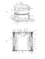
図2は、ベース2のハウジング2Hを除去した内部を示すもので、(a)は斜視図、(b)は縦断面図である。概ね矩形上の底板11の中心には、モータM1が、その回転軸12が上方を向くようにして配置されている。モータM1の外周部には、モータM1本体と所定の間隔を有して上方に開口部13aを有する円筒状のモータカバー13が配置されており、回転軸12の先端には、円板状の取付部材14が固定されている。取付部材14の直径は、開口部13aの直径よりも小さく設定されている。取付部材14には、アーム3を関節J1周りで回転させるため、アーム3が搭載されて固定される略円形の天板15がボルト16によりねじ止めされて取り付けられている。
2 shows the inside of the base 2 with the
さらにその外側には、モータカバー13の下半分を覆うように、何れも円管状の部材であり、同心で2重に配置される固定側ケーブルガイド17,18がボルト19によりねじ止めされて底板11に固定されている。固定側ケーブルガイド17,18は、所定の間隔を有して配置され、その間に、複数本のケーブル20をフラット状に並べた状態のケーブル群21が配置される。すなわち、固定側ケーブルガイド17,18の間隔は、ケーブル20の直径よりもやや大きくなるように設定されている(後述する図3参照)。
Further, on the outer side, both are cable-shaped members so as to cover the lower half of the
一方、天板15の下面側には、固定側ケーブルガイド17,18と上下対称となる位置関係で、同心で2重に配置される回転側ケーブルガイド22,23がボルト24によりねじ止めされて配置固定されている。そして、固定側ケーブルガイド17,18と回転側ケーブルガイド22,23とが上下に対向する部分についても、所定の空隙が確保された状態で配置されている。これらのケーブルガイド17,18,22,23の外周側は、図1に示すように、ベース2のハウジング2Hによって覆われている。
On the other hand, on the lower surface side of the
図1に示すように、外側に位置する固定側ケーブルガイド18の正面部分には切り込みが入れられており、その切り込み部分において、U字状の鋼材などで構成されるケーブル下端固定部材25が、その上端側でボルト26によりねじ止めされて固定側ケーブルガイド17に固定されている。ケーブル群21の下端側(一方の先端側)は、ケーブル下端固定部材25からベース2の外側に延びる部分でコネクタ27に接続されており、このコネクタ27を介してコントローラ側に接続されるようになっている。
As shown in FIG. 1, a cut is made in the front portion of the
ケーブル群21は、その下端側がフラット状態を維持したまま、ケーブル下端固定部材25により固定された状態で、図2(a)に示すように、固定側ケーブルガイド17に沿って直線状に延びると、ケーブル20が並んでいる方向についてU字状に折り返されて、回転側ケーブルガイド22,23の間に導入されている。そして、今度は、固定側で延びた方向を遡るように延びると、ケーブル群21の上端側(他方の先端側)がケーブル下端固定部材25の上方に位置する部位に到達する。
When the
ケーブル群21の上端側は、同様にフラット状態を維持したまま、上記の位置で、固定部材25と同様の構成であるケーブル上端固定部材28により固定されている。ケーブル上端固定部材28は、ボルト29(図1参照)によりねじ止めされて内側に位置する回転側ケーブルガイド22に固定されている。そこから、ケーブル群21の上端側は上方に延びるとロボット1のアーム3〜7の内部に挿入されて、ケーブル20の各先端は、モータM1〜M6等に接続されている。
The upper end side of the
また、本実施例の構成では、ケーブル群21は2組配置されており、各ケーブル群21の上端と下端とが互いに対向するように、左右対称となるように配置されている。すなわち、逆側では、図2(a)に示すように、各ケーブル群21のU字をなすR部分の外側が互いに対向した状態となっている。そして、ケーブル20は必ずしも電気配線を行うものに限らず、例えば圧縮空気を輸送するものであったり、真空吸着を行うための吸引用のケーブルなどを含んでいても良い。
以上において、ハウジング2H,底板11,モータカバー13,固定側ケーブルガイド17,18並びには、固定部30を構成しており、天板15及び回転側ケーブルガイド22,23は、回転部31を構成している。
In the configuration of the present embodiment, two sets of
In the above, the
図3は、固定側ケーブルガイド17,18並びに回転側ケーブルガイド22,23によりそれぞれ形成される空隙長を規定する原理を説明するもので、回転側ケーブルガイド22,23と、それらの間に位置する2本のケーブル20A,20Bとの断面を模式的に示している。図3では、下方に位置するケーブル20Bの中心に対して、上方に位置するケーブル20Aの中心が、外側に45度だけずれた状態を示している。
FIG. 3 explains the principle of defining the lengths of the gaps formed by the fixed cable guides 17 and 18 and the rotary cable guides 22 and 23, respectively. The rotary cable guides 22 and 23 are positioned between them. The cross section of the two
すなわち、回転側ケーブルガイド22,23の空隙長が、ケーブル20の直径Dよりも大きく設定されていると、図3に示すように、上方に位置するケーブル20Aが外側にずれ込むことが想定される。後述するように、ベース2に対してアーム3が回転する場合、ケーブル群21はフラット状態を維持することが望ましいので、上記空隙長について上限を適切に設定すれば上方側のケーブル20Aの過剰な脱落を効果的に防止できる。この場合、上方に位置するケーブル20Aの中心ずれを、外側に45度未満とするよう規定している。ずれが丁度45度になる場合の回転側ケーブルガイド22,23の空隙長は、ケーブル20の直径をDとすると、
(D/2)×2+D/21/2=(1+/21/2)D≒1.7D
となる。したがって、上記空隙長は、ケーブル20の直径の1.7倍未満(例えば1.5倍など)に設定するのが適切であると言える。
That is, when the gap length of the rotation-side cable guides 22 and 23 is set to be larger than the diameter D of the
(D / 2) × 2 + D / 2 1/2 = (1 + / 2 1/2 ) D≈1.7D
It becomes. Therefore, it can be said that it is appropriate to set the gap length to less than 1.7 times the diameter of the cable 20 (for example, 1.5 times).
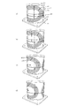
次に、本実施例の作用について図4も参照して説明する。図4は、初期状態として、ケーブル群21の上端と下端とが上下に並ぶ位置(a)から、ベース2の回転部を回転させた場合に、ケーブル群21がどのように動くのかを、U字をなすR部分を中心に示したものである。この場合、ケーブルガイド17,18,22,23等は透明の部材で構成されているとする。
図4(a)に示す初期位置において、固定側ケーブルガイド18と、回転側ケーブルガイド23とに上下矢印の先端が一致するようにマーキングをしており、内部のケーブル群21を構成する各ケーブル20にも直線状のラインをマーキングしている。また、回転側ケーブルガイド23には、右向き矢印の先端が、ケーブル群21のR部分に付した水平状のラインに一致するようにマーキングしている。
Next, the operation of this embodiment will be described with reference to FIG. FIG. 4 shows, as an initial state, how the
In the initial position shown in FIG. 4A, the fixed
この状態から、天板15側の回転部31を、上方から見たとした時計回り(CW)に回転させて行く。すると、図4(b)では、回転側ケーブルガイド23の下向き矢印が図中左方向に移動しており、それに伴い、ケーブル群21の上端側も図中左方向に引っ張られ、R部分も全体が左側に移動している。また、回転側ケーブルガイド23の右向き矢印先端に対して、R部分に付した水平状のラインは上方に移動している。
From this state, the
そこから、回転部31を更に時計回りに回転させると、図4(c)では、回転側ケーブルガイド23の右向き矢印が、初期位置を示す縦軸一点鎖線よりも左側に移動し、ケーブル群21のR部分は、上記一点鎖線により近付いている。そして、R部分では、ケーブル群21の最も内側に位置するケーブル20Iは、最も外側に位置するケーブル20Oよりも見かけ上の移動量が多くなっている。その結果、各ケーブル20の移動量の差に応じて、図4(a)の初期位置では、右向き矢印の先端に一致していた水平状のラインは、段をなすようにずれている
Then, when the rotating
回転部を更に時計回りに回転させた図4(d)では、上記の傾向がより明確になっておいる。また、もう一方のケーブル群21のR部分の後端が、図中右方向から回り込んできている。尚、図4(a)の初期位置から、回転部31を時計回り,反時計周り(CCW)に回転させる範囲は、例えば±170度程度となっている。
すなわち、回転部31を回転させると、ケーブル群21は、U字に折り曲げられてフラットな状態を維持したまま、回転部31の動きに追従している。
In FIG. 4D in which the rotating part is further rotated clockwise, the above tendency becomes clearer. In addition, the rear end of the R portion of the
That is, when the rotating
ここで、図5は、比較のため、従来のロボットにおけるケーブルの配置構造を、図2(b)に示す断面構造に近いもので示している。従来の場合、ケーブル32は、バラ線が1つにまとめられた1本の太いケーブルであり、モータカバー13と、ベース2のハウジング2Hとの間に形成される空間には、本実施例では固定側に相当するケーブルガイド33だけが設けられている。ケーブル32は、U字をなすように上下方向に折り曲げられているが、天板15を中心とする回転側が回転して、ケーブル32の上端側が追従しようとすると、固定されているケーブルガイド33との間に大きな摩擦を生じることになる。
Here, for comparison, FIG. 5 shows a cable arrangement structure in a conventional robot with a structure close to the cross-sectional structure shown in FIG. In the conventional case, the
これに対して、本実施例の構成では、複数の細いケーブル20をフラット状にまとめたケーブル群21として、ベース2のモータカバー13に沿うように配置し、ケーブル群21が水平方向に占める幅が少なくなっている。そして、回転部31が回転する場合には、回転側ケーブルガイド22,23も一体に回転するので、ケーブル群21の上端側が追従しようとする場合に生じる摩擦も極めて少なくなっている。
On the other hand, in the configuration of the present embodiment, a plurality of
以上のように本実施例によれば、複数のケーブル20は、ベース2の内部において、固定側ケーブルガイド17,回転側ケーブルガイド22(これらが「回転部の外周部」に相当)に沿ったままフラット状に配置される。そして、回転部31が回転動作すると、ケーブル群21は、固定側ケーブルガイド17,回転側ケーブルガイド22の外周に沿ってU字をなすように曲げられた状態のまま、上端側がその回転動作に応じて移動することで追従する。この時、ケーブル群21のR部分は回転方向に対応して移動するように動くが、ケーブル群21の直線をなす部分、つまり回転側ケーブルガイド22,23により保持されている部分は、回転部31及び回転側ケーブルガイド22,23と一体に回転する。
As described above, according to the present embodiment, the plurality of
すなわち、ベース2が回転動作する場合、ケーブル群21にはR部分にしか摩擦が発生しないので、摩擦を大きく軽減することができ、回転をスムーズに行うことができる。したがって、ケーブル群21を固定側ケーブルガイド17,回転側ケーブルガイド22の
外周に沿ってベース2の内部にコンパクトに配置することができ、回転動作を阻害することなく省スペース化を図ることが可能になる。また、各ケーブル20に係る負荷も軽減されるので損傷が発生し難くなり、信頼性を向上させることもできる。
That is, when the base 2 rotates, friction is generated only in the R portion of the
また、本実施例によれば、コントローラとロボット1との間を、2つのケーブル群21に分けて接続する場合、一方のケーブル群21の先端部と他方のケーブル群21の先端部とが、互いに対向するように固定することで、それらを左右対象に配置した。したがって、回転部31が回転する方向が何れであっても、各ケーブル群21が互いに邪魔をすることなく、固定側ケーブルガイド17,回転側ケーブルガイド22の外周に沿った状態で移動するので、コントローラとロボット1との間を接続するケーブル20の本数が多くなる場合でも、回転動作を阻害することなく省スペース化を図ることができる。
In addition, according to the present embodiment, when the controller and the
更に、本実施例によれば、固定側ケーブルガイド17,18並びに回転側ケーブルガイド22,23により形成される空隙長を、ケーブル20の直径Dの1.7倍未満に設定するので、ケーブル20の柔軟性が比較的低いため、重力によって一部が垂れ下がろうとする場合でも、上方のケーブル20の中心が下方のケーブル20の中心に対して45度未満で外側にずれた状態に留まるようになり、スムーズな回転動作を維持できる。
Furthermore, according to the present embodiment, the gap length formed by the fixed cable guides 17 and 18 and the rotary cable guides 22 and 23 is set to be less than 1.7 times the diameter D of the
(第2実施例)
図6は第2実施例を示す図2(b)相当図である。第2実施例では、固定側ケーブルガイド17,18並びに回転側ケーブルガイド22,23に替えて、断面がU字状をなしてそれぞれが一体の部材である固定側ケーブルガイド41並びに回転側ケーブルガイド42が配置されている。そして、断面がU字状をなす部分で形成されている空隙長は、第1実施例と同様にケーブル20の直径Dの1.7倍未満に設定されている。
(Second embodiment)
FIG. 6 is a view corresponding to FIG. 2B showing the second embodiment. In the second embodiment, instead of the fixed-side cable guides 17 and 18 and the rotary-side cable guides 22 and 23, the fixed-
以上のように構成される第2実施例によれば、固定側ケーブルガイド41,回転側ケーブルガイド42を、断面形状が所定の空隙を有するU字状で且つ全体が円管型をなす部材により構成し、ケーブル群21を、ケーブルガイド41,42のU字をなす部分で保持するので、第1実施例と同様に、回転部31Aが回転動作する場合、ケーブル群21にはR部分にしか摩擦が発生せず、同様の効果が得られる。
According to the second embodiment configured as described above, the fixed-
本発明は上記し又は図面に記載した実施例にのみ限定されるものではなく、以下のような変形又は拡張が可能である。
必要な配線数を満たすことができれば、ケーブル群21を1つだけ配置しても良い。
モータカバー13は、必要に応じて設ければ良い。また、ハウジング2Hを除去して、外周側に位置するケーブルガイド18,23をその代わりとしても良い。
あるいは、モータカバー13に相当する部材MCを水平方向に2分割し、その上方側部材MC_Uを回転軸12に結合して回転部としても良い。そして、外周側に位置する固定側ケーブルガイド18,回転側ケーブルガイド23を除去し、ケーブル群21を、下方側部材MC_Dと固定側ケーブルガイド17との間,上方側部材MC_Uと回転側ケーブルガイド22との間に配置しても良い。この場合、部材MCの外周が「回転軸の外周部」に相当する。
ケーブルガイドによる空隙長の設定は、適宜変更して良い。
ロボットの軸数は6軸に限ることはない。また、垂直多関節型に限ることなく、水平多関節型のロボットに適用しても良い。
The present invention is not limited to the embodiments described above or shown in the drawings, and the following modifications or expansions are possible.
If the required number of wires can be satisfied, only one
The
Alternatively, the member MC corresponding to the
The setting of the gap length by the cable guide may be changed as appropriate.
The number of robot axes is not limited to six. Further, the present invention is not limited to the vertical articulated type, and may be applied to a horizontal articulated type robot.
図面中、1はロボット、2はベース(回転軸)、17,18は固定側ケーブルガイド、
20はケーブル、21はケーブル群、22,23は回転側ケーブルガイド、25はケーブル下端固定部材、28はケーブル上端固定部材、30は固定部、31は回転部、41は固定側ケーブルガイド、42は回転側ケーブルガイド、M1〜M6はサーボモータを示す。
In the drawings, 1 is a robot, 2 is a base (rotating shaft), 17 and 18 are fixed side cable guides,
Claims (4)
前記回転軸は、上底側と下底側とに分離されており、前記下底側が固定される固定部,前記上底側が回転動作する回転部となるもので、
前記複数のケーブルは、フラット状に並ぶようにまとめられた状態で、その一方の先端部は前記固定部の外周に沿って固定部材により固定され、前記複数のケーブルが並ぶ方向についてU字をなすように曲げられると、他方の先端部が、前記回転部の外周に沿って固定部材により固定され、
前記複数のケーブルを前記回転軸の外周部に沿わせた状態で保持するように円管型をなす部材からなり、前記固定部の外周部との間に所定の空隙を有するように配置される固定側ケーブルガイドと、前記回転部の外周部との間に所定の空隙を有するように配置され、当該回転部と一体に回転する回転側ケーブルガイドとを備えたことを特徴とするロボット回転軸のケーブル保持構造。 A rotary shaft of a robot whose outer shape is cylindrical, and a structure for holding a plurality of cables connecting a motor and a controller arranged on each axis of the articulated arm of the robot,
The rotating shaft is separated into an upper bottom side and a lower bottom side, and is a fixed portion to which the lower bottom side is fixed, and a rotating portion in which the upper bottom side rotates.
The plurality of cables are arranged so as to be arranged in a flat shape, and one end portion thereof is fixed by a fixing member along the outer periphery of the fixing portion, and forms a U-shape in the direction in which the plurality of cables are arranged. The other tip is fixed by a fixing member along the outer periphery of the rotating part,
It consists of a member that forms a circular tube shape so as to hold the plurality of cables along the outer peripheral portion of the rotating shaft, and is arranged so as to have a predetermined gap between the outer peripheral portion of the fixed portion. A robot rotation shaft comprising a rotation-side cable guide that is disposed so as to have a predetermined gap between a fixed-side cable guide and an outer peripheral portion of the rotation unit and rotates integrally with the rotation unit. Cable holding structure.
前記回転軸は、上底側と下底側とに分離されており、前記下底側が固定される固定部,前記上底側が回転動作する回転部となるもので、
前記複数のケーブルは、フラット状に並ぶようにまとめられた状態で、その一方の先端部は前記固定部の外周に沿って固定部材により固定され、前記複数のケーブルが並ぶ方向についてU字をなすように曲げられると、他方の先端部が、前記回転部の外周に沿って固定部材により固定され、
前記複数のケーブルを前記回転軸の外周部に沿わせた状態で保持するように断面形状が所定の空隙を有するU字状で且つ全体が円管型をなす部材からなり、前記固定部の外周部に、前記U字の開放側が下方を向くように配置される固定側ケーブルガイドと、前記回転部の外周部に、前記U字の開放側が上方を向くように配置され、当該回転部と一体に回転する回転側ケーブルガイドとを備えたことを特徴とするロボット回転軸のケーブル保持構造。 A rotary shaft of a robot whose outer shape is cylindrical, and a structure for holding a plurality of cables connecting a motor and a controller arranged on each axis of the articulated arm of the robot,
The rotating shaft is separated into an upper bottom side and a lower bottom side, and is a fixed portion to which the lower bottom side is fixed, and a rotating portion in which the upper bottom side rotates.
The plurality of cables are arranged so as to be arranged in a flat shape, and one end portion thereof is fixed by a fixing member along the outer periphery of the fixing portion, and forms a U-shape in the direction in which the plurality of cables are arranged. The other tip is fixed by a fixing member along the outer periphery of the rotating part,
The cross-sectional shape is a U-shape having a predetermined gap so as to hold the plurality of cables in a state along the outer peripheral portion of the rotary shaft, and the entire outer periphery of the fixed portion is a tube-shaped member. A fixed-side cable guide that is arranged so that the open side of the U-shape faces downward, and an outer peripheral portion of the rotating portion that is arranged so that the open side of the U-shape faces upward, and is integrated with the rotating portion A cable holding structure for a rotary shaft of a robot characterized by comprising a rotating side cable guide that rotates on the rotating side.
一方のケーブル群の先端部と他方のケーブル群の先端部とが、互いに対向するように前記固定部材により固定されることで、2つのケーブル群が左右対象に配置されることを特徴とする請求項1又は2記載のロボット回転軸のケーブル保持構造。 When the plurality of cables are divided into two groups and connected,
The front end portion of one cable group and the front end portion of the other cable group are fixed by the fixing member so as to face each other, whereby the two cable groups are arranged on the left and right sides. Item 3. The cable holding structure of the robot rotation shaft according to Item 1 or 2.
Priority Applications (3)
| Application Number | Priority Date | Filing Date | Title |
|---|---|---|---|
| JP2009142306A JP5375353B2 (en) | 2009-06-15 | 2009-06-15 | Cable holding structure for robot rotation axis |
| DE102010017358.4A DE102010017358B4 (en) | 2009-06-15 | 2010-06-14 | Device for holding cables in a rotatable shaft of a robot |
| US12/814,679 US20100313694A1 (en) | 2009-06-15 | 2010-06-14 | Apparatus for holding cables in rotary shaft of robot |
Applications Claiming Priority (1)
| Application Number | Priority Date | Filing Date | Title |
|---|---|---|---|
| JP2009142306A JP5375353B2 (en) | 2009-06-15 | 2009-06-15 | Cable holding structure for robot rotation axis |
Publications (2)
| Publication Number | Publication Date |
|---|---|
| JP2010284777A JP2010284777A (en) | 2010-12-24 |
| JP5375353B2 true JP5375353B2 (en) | 2013-12-25 |
Family
ID=43305238
Family Applications (1)
| Application Number | Title | Priority Date | Filing Date |
|---|---|---|---|
| JP2009142306A Active JP5375353B2 (en) | 2009-06-15 | 2009-06-15 | Cable holding structure for robot rotation axis |
Country Status (3)
| Country | Link |
|---|---|
| US (1) | US20100313694A1 (en) |
| JP (1) | JP5375353B2 (en) |
| DE (1) | DE102010017358B4 (en) |
Families Citing this family (27)
| Publication number | Priority date | Publication date | Assignee | Title |
|---|---|---|---|---|
| JPWO2009069389A1 (en) * | 2007-11-26 | 2011-04-07 | 株式会社安川電機 | Vertical articulated robot |
| JP5893310B2 (en) * | 2011-09-26 | 2016-03-23 | 株式会社デンソーウェーブ | Cable protection guide member mounting structure and robot including the mounting structure |
| GB2502611B (en) * | 2012-06-01 | 2017-03-15 | Tidal Generation Ltd | Connection systems |
| US9579806B2 (en) | 2012-08-23 | 2017-02-28 | Rethink Robotics, Inc. | Robotic power and signal distribution using laminated cable with separator webs |
| CN103042536A (en) * | 2013-01-23 | 2013-04-17 | 北京理工大学 | Winding preventing device for rotation joint of robot |
| US9802327B2 (en) | 2013-09-10 | 2017-10-31 | Seiko Epson Corporation | Robot arm and robot |
| JP6337432B2 (en) | 2013-09-10 | 2018-06-06 | セイコーエプソン株式会社 | Joint drive device and robot |
| JP6163989B2 (en) * | 2013-09-13 | 2017-07-19 | セイコーエプソン株式会社 | Robot arm and robot |
| CN104440941B (en) * | 2013-09-13 | 2018-02-13 | 精工爱普生株式会社 | Mechanical arm and robot |
| DE202013104544U1 (en) | 2013-10-08 | 2015-01-15 | Daimler Ag | working device |
| JP2016022570A (en) * | 2014-07-24 | 2016-02-08 | 株式会社安川電機 | robot |
| JP2016022571A (en) * | 2014-07-24 | 2016-02-08 | 株式会社安川電機 | Joint mechanism of robot and robot |
| WO2016045069A1 (en) | 2014-09-26 | 2016-03-31 | Abb Technology Ltd | A routing unit, a rotary joint and a robot |
| JP2016068199A (en) * | 2014-09-30 | 2016-05-09 | セイコーエプソン株式会社 | robot |
| CN106687259B (en) * | 2014-11-19 | 2018-11-20 | Abb瑞士股份有限公司 | Cable management system, rotary joint and robot |
| JP5975129B1 (en) | 2015-03-02 | 2016-08-23 | 株式会社安川電機 | robot |
| JP6511939B2 (en) * | 2015-04-27 | 2019-05-15 | セイコーエプソン株式会社 | robot |
| JP6582520B2 (en) * | 2015-04-28 | 2019-10-02 | セイコーエプソン株式会社 | robot |
| JP2017131969A (en) * | 2016-01-25 | 2017-08-03 | セイコーエプソン株式会社 | robot |
| JP6441254B2 (en) * | 2016-04-05 | 2018-12-19 | ファナック株式会社 | Robot striatum processing structure |
| JP2018001315A (en) | 2016-06-29 | 2018-01-11 | セイコーエプソン株式会社 | Robot, control device, and robot system |
| CN110267777A (en) * | 2017-04-28 | 2019-09-20 | Abb瑞士股份有限公司 | Core of a cable management module and robot |
| JP6988152B2 (en) * | 2017-05-08 | 2022-01-05 | セイコーエプソン株式会社 | robot |
| US10675770B2 (en) | 2017-08-23 | 2020-06-09 | Integrated Packaging Machinery, LLC | Fluid and cable management adapter for delivering utilities to an operable machine component |
| CN110202611B (en) | 2018-02-28 | 2023-07-11 | 精工爱普生株式会社 | Robot |
| US10836052B2 (en) * | 2019-02-06 | 2020-11-17 | Hiwin Technologies Corp. | Connection module using in robot |
| DE102019130979B3 (en) * | 2019-11-15 | 2020-12-10 | Ab Elektronik Gmbh | Pedal encoder for motor vehicles, pedal encoder arrangement and method for controlling a motor vehicle |
Family Cites Families (12)
| Publication number | Priority date | Publication date | Assignee | Title |
|---|---|---|---|---|
| GB1575287A (en) * | 1977-05-25 | 1980-09-17 | Westinghouse Electric Corp | Connecting apparatus for limited rotary or rectillinear motion |
| CH651427A5 (en) * | 1981-05-13 | 1985-09-13 | Adna Ag | DEVICE FOR CHARGING A POWER SUPPLY CABLE. |
| US4499341A (en) * | 1982-09-22 | 1985-02-12 | Amp Incorporated | Extensible electrical cable assembly |
| JPS60217092A (en) * | 1984-04-13 | 1985-10-30 | ファナック株式会社 | Cable supporter for industrial robot |
| JP2598137B2 (en) * | 1989-10-05 | 1997-04-09 | 川崎重工業株式会社 | Industrial robot |
| JP2529894Y2 (en) * | 1990-06-14 | 1997-03-19 | アルプス電気株式会社 | Cable reel |
| US5694813A (en) * | 1996-09-23 | 1997-12-09 | Nachi Robotics Systems Inc. | Industrial robot |
| DE19850452B4 (en) * | 1997-11-07 | 2013-12-12 | Nachi-Fujikoshi Corp. | Holding device for switching connections and piping of an industrial robot |
| SE511643C2 (en) * | 1998-10-16 | 1999-11-01 | Abb Ab | Control of external cables for industrial robot |
| JP4099628B2 (en) * | 2001-10-29 | 2008-06-11 | 株式会社安川電機 | Industrial robot |
| JP2006187841A (en) | 2005-01-07 | 2006-07-20 | Mitsubishi Electric Corp | Industrial robot |
| JP2007125651A (en) * | 2005-11-04 | 2007-05-24 | Yaskawa Electric Corp | Industrial robot |
-
2009
- 2009-06-15 JP JP2009142306A patent/JP5375353B2/en active Active
-
2010
- 2010-06-14 DE DE102010017358.4A patent/DE102010017358B4/en active Active
- 2010-06-14 US US12/814,679 patent/US20100313694A1/en not_active Abandoned
Also Published As
| Publication number | Publication date |
|---|---|
| DE102010017358A1 (en) | 2011-03-03 |
| US20100313694A1 (en) | 2010-12-16 |
| DE102010017358B4 (en) | 2021-04-22 |
| JP2010284777A (en) | 2010-12-24 |
Similar Documents
| Publication | Publication Date | Title |
|---|---|---|
| JP5375353B2 (en) | Cable holding structure for robot rotation axis | |
| KR930002624B1 (en) | Industrial robot equipped with a cable extending means | |
| US7202442B2 (en) | Cable arrangement for robot arm, and industrial robot utilizing the same | |
| JP6670455B2 (en) | Robots and robot systems | |
| EP2977152A2 (en) | Robot | |
| CN106687259A (en) | A cable-management system, a rotary joint and a robot | |
| US20180236671A1 (en) | Robot | |
| US20160023359A1 (en) | Robot joint mechanism and robot | |
| JP2008307635A (en) | Robot | |
| JP2006525130A (en) | Industrial robot | |
| WO2018003631A1 (en) | Robot arm mechanism and rotation joint mechanism | |
| US20160023358A1 (en) | Robot | |
| KR101086295B1 (en) | Articulated robot | |
| US20170210016A1 (en) | Robot | |
| JP2016203345A (en) | robot | |
| JP2016068201A (en) | robot | |
| JP2009226567A (en) | Scalar robot | |
| WO2021005968A1 (en) | Suspended industrial robot | |
| WO2024036807A1 (en) | Robot joint module and robot | |
| JP2006026748A (en) | Robot wrist mechanism and operation method of end effector fitted thereto | |
| JP3452811B2 (en) | Wiring and piping support device for industrial robots | |
| KR200277585Y1 (en) | Outer cable harness device of Selective Compliance Assembly Robot Arm for industrial | |
| JP7069757B2 (en) | Horizontal articulated robot | |
| JP6260137B2 (en) | Industrial robot | |
| JPH0351114Y2 (en) |
Legal Events
| Date | Code | Title | Description |
|---|---|---|---|
| A621 | Written request for application examination |
Free format text: JAPANESE INTERMEDIATE CODE: A621 Effective date: 20120113 |
|
| A131 | Notification of reasons for refusal |
Free format text: JAPANESE INTERMEDIATE CODE: A131 Effective date: 20130226 |
|
| TRDD | Decision of grant or rejection written | ||
| A01 | Written decision to grant a patent or to grant a registration (utility model) |
Free format text: JAPANESE INTERMEDIATE CODE: A01 Effective date: 20130827 |
|
| A61 | First payment of annual fees (during grant procedure) |
Free format text: JAPANESE INTERMEDIATE CODE: A61 Effective date: 20130909 |
|
| R150 | Certificate of patent or registration of utility model |
Ref document number: 5375353 Country of ref document: JP Free format text: JAPANESE INTERMEDIATE CODE: R150 |
|
| R250 | Receipt of annual fees |
Free format text: JAPANESE INTERMEDIATE CODE: R250 |
|
| R250 | Receipt of annual fees |
Free format text: JAPANESE INTERMEDIATE CODE: R250 |
|
| R250 | Receipt of annual fees |
Free format text: JAPANESE INTERMEDIATE CODE: R250 |
|
| R250 | Receipt of annual fees |
Free format text: JAPANESE INTERMEDIATE CODE: R250 |
|
| R250 | Receipt of annual fees |
Free format text: JAPANESE INTERMEDIATE CODE: R250 |
|
| R250 | Receipt of annual fees |
Free format text: JAPANESE INTERMEDIATE CODE: R250 |
|
| R250 | Receipt of annual fees |
Free format text: JAPANESE INTERMEDIATE CODE: R250 |
|
| R250 | Receipt of annual fees |
Free format text: JAPANESE INTERMEDIATE CODE: R250 |