EP2211172B1 - Procédé de fabrication d'un outil d'analyse - Google Patents
Procédé de fabrication d'un outil d'analyse Download PDFInfo
- Publication number
- EP2211172B1 EP2211172B1 EP08845459.0A EP08845459A EP2211172B1 EP 2211172 B1 EP2211172 B1 EP 2211172B1 EP 08845459 A EP08845459 A EP 08845459A EP 2211172 B1 EP2211172 B1 EP 2211172B1
- Authority
- EP
- European Patent Office
- Prior art keywords
- electrode
- reactive electrode
- area
- reactive
- biosensor
- Prior art date
- Legal status (The legal status is an assumption and is not a legal conclusion. Google has not performed a legal analysis and makes no representation as to the accuracy of the status listed.)
- Active
Links
- 238000004519 manufacturing process Methods 0.000 title claims description 19
- 125000006850 spacer group Chemical group 0.000 claims description 42
- 239000000758 substrate Substances 0.000 claims description 32
- 238000000034 method Methods 0.000 claims description 23
- 239000003153 chemical reaction reagent Substances 0.000 claims description 16
- 238000012546 transfer Methods 0.000 claims description 11
- 230000001678 irradiating effect Effects 0.000 claims description 4
- 238000005259 measurement Methods 0.000 description 15
- WQZGKKKJIJFFOK-GASJEMHNSA-N Glucose Natural products OC[C@H]1OC(O)[C@H](O)[C@@H](O)[C@@H]1O WQZGKKKJIJFFOK-GASJEMHNSA-N 0.000 description 8
- 238000010586 diagram Methods 0.000 description 8
- 239000008103 glucose Substances 0.000 description 8
- 230000027756 respiratory electron transport chain Effects 0.000 description 8
- 238000000926 separation method Methods 0.000 description 8
- 239000008280 blood Substances 0.000 description 7
- 210000004369 blood Anatomy 0.000 description 7
- 108091006149 Electron carriers Proteins 0.000 description 6
- 108090000854 Oxidoreductases Proteins 0.000 description 6
- 102000004316 Oxidoreductases Human genes 0.000 description 6
- 239000012876 carrier material Substances 0.000 description 6
- 108010015776 Glucose oxidase Proteins 0.000 description 5
- 239000004366 Glucose oxidase Substances 0.000 description 5
- 235000019420 glucose oxidase Nutrition 0.000 description 5
- 229940116332 glucose oxidase Drugs 0.000 description 5
- 239000000463 material Substances 0.000 description 5
- 230000035945 sensitivity Effects 0.000 description 5
- 108010050375 Glucose 1-Dehydrogenase Proteins 0.000 description 4
- PXHVJJICTQNCMI-UHFFFAOYSA-N Nickel Chemical compound [Ni] PXHVJJICTQNCMI-UHFFFAOYSA-N 0.000 description 4
- 238000005452 bending Methods 0.000 description 4
- HVYWMOMLDIMFJA-DPAQBDIFSA-N cholesterol Chemical compound C1C=C2C[C@@H](O)CC[C@]2(C)[C@@H]2[C@@H]1[C@@H]1CC[C@H]([C@H](C)CCCC(C)C)[C@@]1(C)CC2 HVYWMOMLDIMFJA-DPAQBDIFSA-N 0.000 description 4
- 238000005520 cutting process Methods 0.000 description 4
- 230000000694 effects Effects 0.000 description 4
- JVTAAEKCZFNVCJ-UHFFFAOYSA-N lactic acid Chemical compound CC(O)C(O)=O JVTAAEKCZFNVCJ-UHFFFAOYSA-N 0.000 description 4
- 238000012360 testing method Methods 0.000 description 4
- 229920002978 Vinylon Polymers 0.000 description 3
- 239000002390 adhesive tape Substances 0.000 description 3
- 239000012943 hotmelt Substances 0.000 description 3
- SQEHCNOBYLQFTG-UHFFFAOYSA-M lithium;thiophene-2-carboxylate Chemical compound [Li+].[O-]C(=O)C1=CC=CS1 SQEHCNOBYLQFTG-UHFFFAOYSA-M 0.000 description 3
- 239000000126 substance Substances 0.000 description 3
- 229920005992 thermoplastic resin Polymers 0.000 description 3
- KDLHZDBZIXYQEI-UHFFFAOYSA-N Palladium Chemical compound [Pd] KDLHZDBZIXYQEI-UHFFFAOYSA-N 0.000 description 2
- 239000012327 Ruthenium complex Substances 0.000 description 2
- WQZGKKKJIJFFOK-VFUOTHLCSA-N beta-D-glucose Chemical compound OC[C@H]1O[C@@H](O)[C@H](O)[C@@H](O)[C@@H]1O WQZGKKKJIJFFOK-VFUOTHLCSA-N 0.000 description 2
- 235000012000 cholesterol Nutrition 0.000 description 2
- 235000001727 glucose Nutrition 0.000 description 2
- XEEYBQQBJWHFJM-UHFFFAOYSA-N iron Substances [Fe] XEEYBQQBJWHFJM-UHFFFAOYSA-N 0.000 description 2
- 150000004698 iron complex Chemical class 0.000 description 2
- 235000014655 lactic acid Nutrition 0.000 description 2
- 239000004310 lactic acid Substances 0.000 description 2
- 239000007791 liquid phase Substances 0.000 description 2
- 229910052759 nickel Inorganic materials 0.000 description 2
- 238000000206 photolithography Methods 0.000 description 2
- BASFCYQUMIYNBI-UHFFFAOYSA-N platinum Chemical compound [Pt] BASFCYQUMIYNBI-UHFFFAOYSA-N 0.000 description 2
- 238000004544 sputter deposition Methods 0.000 description 2
- 210000002700 urine Anatomy 0.000 description 2
- OKTJSMMVPCPJKN-UHFFFAOYSA-N Carbon Chemical compound [C] OKTJSMMVPCPJKN-UHFFFAOYSA-N 0.000 description 1
- 230000015572 biosynthetic process Effects 0.000 description 1
- 229910052799 carbon Inorganic materials 0.000 description 1
- 238000000151 deposition Methods 0.000 description 1
- 230000008021 deposition Effects 0.000 description 1
- 229910003460 diamond Inorganic materials 0.000 description 1
- 239000010432 diamond Substances 0.000 description 1
- 238000007599 discharging Methods 0.000 description 1
- PCHJSUWPFVWCPO-UHFFFAOYSA-N gold Chemical compound [Au] PCHJSUWPFVWCPO-UHFFFAOYSA-N 0.000 description 1
- 229910052737 gold Inorganic materials 0.000 description 1
- 239000010931 gold Substances 0.000 description 1
- 238000009413 insulation Methods 0.000 description 1
- 229910052751 metal Inorganic materials 0.000 description 1
- 239000002184 metal Substances 0.000 description 1
- 229910052763 palladium Inorganic materials 0.000 description 1
- 239000012071 phase Substances 0.000 description 1
- 229910052697 platinum Inorganic materials 0.000 description 1
- 238000012545 processing Methods 0.000 description 1
- 229920005989 resin Polymers 0.000 description 1
- 239000011347 resin Substances 0.000 description 1
- 238000007650 screen-printing Methods 0.000 description 1
- 239000007787 solid Substances 0.000 description 1
Images


Classifications
-
- G—PHYSICS
- G01—MEASURING; TESTING
- G01N—INVESTIGATING OR ANALYSING MATERIALS BY DETERMINING THEIR CHEMICAL OR PHYSICAL PROPERTIES
- G01N27/00—Investigating or analysing materials by the use of electric, electrochemical, or magnetic means
- G01N27/26—Investigating or analysing materials by the use of electric, electrochemical, or magnetic means by investigating electrochemical variables; by using electrolysis or electrophoresis
- G01N27/28—Electrolytic cell components
- G01N27/30—Electrodes, e.g. test electrodes; Half-cells
- G01N27/327—Biochemical electrodes, e.g. electrical or mechanical details for in vitro measurements
- G01N27/3271—Amperometric enzyme electrodes for analytes in body fluids, e.g. glucose in blood
- G01N27/3272—Test elements therefor, i.e. disposable laminated substrates with electrodes, reagent and channels
-
- B—PERFORMING OPERATIONS; TRANSPORTING
- B05—SPRAYING OR ATOMISING IN GENERAL; APPLYING FLUENT MATERIALS TO SURFACES, IN GENERAL
- B05D—PROCESSES FOR APPLYING FLUENT MATERIALS TO SURFACES, IN GENERAL
- B05D5/00—Processes for applying liquids or other fluent materials to surfaces to obtain special surface effects, finishes or structures
- B05D5/12—Processes for applying liquids or other fluent materials to surfaces to obtain special surface effects, finishes or structures to obtain a coating with specific electrical properties
-
- B—PERFORMING OPERATIONS; TRANSPORTING
- B32—LAYERED PRODUCTS
- B32B—LAYERED PRODUCTS, i.e. PRODUCTS BUILT-UP OF STRATA OF FLAT OR NON-FLAT, e.g. CELLULAR OR HONEYCOMB, FORM
- B32B38/00—Ancillary operations in connection with laminating processes
- B32B38/04—Punching, slitting or perforating
Definitions
- the present invention relates to a method of manufacturing an analysis tool used to analyze certain components (for example, glucose, cholesterol, or lactic acid) of a specimen (for example, a biochemical specimen such as blood or urine).
- a specimen for example, a biochemical specimen such as blood or urine.
- the analysis tool includes, for example, an electrode-type biosensor 6 shown in Fig. 16 (for example, refer to Patent Document 1).
- the biosensor 6 is configured such that a response electric current value necessary to calculate a blood-sugar level is measured using electrodes 61 and 62 provided on a substrate 60.
- the electrodes 61 and 62 are covered by an insulating film 64 having an opening 64A, and the portions of the electrodes 61 and 62 exposed by the opening 64A constitute a reactive electrode 61A and a counter electrode 62A.
- the area of the reactive electrode 61A or the counter electrode 62A is controlled by the opening 64A of the insulating film 64.
- a deviation may be generated in the area of the reactive electrode 61A due to a deviation in the dimension of the opening 64A between plural glucose sensors 6.
- the reactive electrode 61A facilitates transfer of electrons from/to analysis target components, and a deviation in the area of the reactive electrode 61A generates a deviation in the sensitivity of the biosensor 6.
- a narrow-width neck section 71 extends from an electrode main body section 70, and the electrode main body section 70 is exposed by the opening 73 of the insulating film 72 (for example, refer to Patent Document 2).
- the edge of the opening 73 in the insulating film 72 traverses the neck section 71. Therefore, even when the dimension of the opening 73 has a deviation, it is possible to suppress a deviation in the area of the electrode main body section 70.
- the electrode strip 8 shown in Fig. 18 has a reactive electrode 80 and a dummy electrode 81.
- the electrodes 80 and 81 are exposed by the opening 83 of the insulating film 82 (for example, refer to Patent Document 3).
- the reactive electrode 80 and the dummy electrode 81 have an island shape, it is possible to prevent the deviation in the area of the reactive electrode 80 even when the deviation exists in the dimension of the opening 83.
- a slit 91 is formed in a metal film of the substrate 90, and the reactive electrode 93 and the counter electrode 94 are controlled by a pair of covers 92 (for example, refer to Patent Document 4).
- the area of the reactive electrode 93 can be controlled without the insulating film, it is possible to advantageously make it easier to perform the manufacturing processes.
- the area of the reactive electrode 93 depends on the accuracy of positioning or the shape of a pair of covers 92, it is difficult to accurately control the area of the reactive electrode 93.
- WO 2008/040997 A1 discloses a test strip comprising patterned electrodes.
- the test strip includes a conductive layer having conductive tracks extending between the proximal end and the distal end of the test strip, a reagent layer, and a top tape.
- WO 00/42422 discloses disposable test strips with integrated reagent/blood separation layer.
- the present invention has been made to control the area of the reactive electrode of the electrode-type analysis tool in a simple, easy, and accurate manner.
- a method of manufacturing an analysis tool comprising: a first process for forming a plurality of electrodes including at least a reactive electrode and a counter electrode on a mother substrate; a second process for forming an element for defining an effective area for performing transfer of electrons at at least one of the reactive electrode or the counter electrode; a third process for defining a contact area that contacts a specimen at the reactive electrode by attaching plural spacers; and applying a reagent solution between the spacers, wherein the second process is performed by forming a plurality of slits in an electrode including the reactive electrode, wherein each slit is formed to have a main line extending in a first direction in which the reactive electrode and the counter electrode are aligned and a subsidiary line extending in a second direction that intersects the first direction, and wherein the spacers are attached in such a manner that the main lines of the silts are exposed, and the spacers are attached farther than a distance between the main lines of
- the slit is formed by irradiating laser light onto the electrode.
- the first process is performed by irradiating laser light onto the conductive layer after a conductive layer is formed on the mother substrate.
- an analysis tool including: a substrate; a first electrode which is formed on the substrate and has a reactive electrode; a second electrode which is formed on the substrate and has a counter electrode; a first control element for controlling a contact area making contact with a specimen in the reactive electrode; and a second control element for controlling an effective area for performing transfer of electrons in at least one of the reactive electrode and the counter electrode.
- the second control element is provided to control the effective area for performing transfer of electrons in the reactive electrode.
- the second control element is at least a slit.
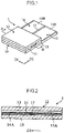
- the biosensor 1 shown in Figs. 1 to 3 is constructed as a disposable device, and is installed in an analyzer (not shown) such as a concentration measurement apparatus and used to analyze a certain component (for example, glucose, cholesterol, or lactic acid) within a specimen (for example, a biochemical specimen such as blood or urine).
- the biosensor 1 has a configuration obtained by bonding the cover 12 to the substrate 10 having an approximately long rectangular shape by interposing a pair of spacers 11 therebetween.
- a capillary 13 extending in the width direction D1 of the substrate 10 is defined by each element 10 to 12.
- the substrate 10 is formed in a shape larger than the cover 12 using an insulation resin material such as PET.
- the substrate 10 has a protrusion in a lateral direction of the cover 12.
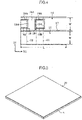
- electrodes 14 and 15 and a reagent layer 16 are provided on the surface of the substrate 10.
- the electrodes 14 and 15 are formed to have a band shape extending in the longitudinal direction D2 of the substrate 10 such that, for example, the length L is 2 to 50 mm (refer to Fig. 4 ), and the width W is 0.1 to 5 mm (refer to Fig. 4 ).
- the electrodes 14 and 15 have exposed electrode portions (including the reactive electrode 14A and the counter electrode 15A) and terminal portions 14B and 15B.
- the reactive electrode 14A and the counter electrode 15A are exposed portions inside the capillary 13 and separated from each other by the slit 17.
- the width of the slit 17 is set to, for example, 10 to 300 ⁇ m.
- the reactive electrode 14A and the counter electrode 15A make contact with the specimen introduced into the capillary 13.
- the reactive electrode 14A performs transfer of electrons from/to analysis target components within the specimen, and the area of the reactive electrode 14A influences the measurement accuracy of the biosensor 1.
- the electrode 14 further includes slits 18 and 19. These slits 18 and 19 are provided to define an effective area, and include main lines 18A and 19A, and subsidiary lines 18B and 19B.
- the effective area of the reactive electrode 14A means the area of the portion for performing transfer of electrons from/to the analysis target components within the specimen.
- the reactive electrode 14A has a smaller effective area which is an area for performing transfer of electrons from/to analysis target components within the specimen by providing slits 18 and 19 in comparison with the area making contact with the specimen inside the capillary 13.
- the area of the reactive electrode 14A substantially contributing to such transfer of electrons is referred to as an effective area.
- the main lines 18A and 19A extend in a direction of D1, and their lengths are set to, for example, 50 to 98% of the widths W of the electrodes 14 and 15.
- the distance between the main lines 18A and 19A is set to, for example, 30% to 98% of the distance between a pair of the spacers 11.
- the subsidiary lines 18B and 19B extend in the direction of D2.
- the slit 18 has a U-shape
- the slit 19 has a rectangular shape.
- the terminal portions 14B and 15B are provided to make contact with a connector (not shown) of the analyzer when the biosensor 1 is installed in the analyzer.
- the reagent layer 16 is to cover the reactive electrode 14A and the counter electrode 15Ain series inside the capillary 13.
- the reagent layer 16 includes, for example, an oxidoreductase and an electron carrier material, and is formed in a solid state readily dissolved in the specimen such as blood.
- the oxidoreductase is selected depending on the type of the analysis target component within the specimen. For example, when glucose is analyzed, glucose oxidase (GOD) or glucose dehydrogenase (GDH) may be used, and typically, PQQGDH is used.
- the electron carrier material may include, for example, a ruthenium complex or an iron complex, and typically [Ru(NH 3 ) 6 ]Cl 3 or K 3 [Fe(CN) 6 ].
- a pair of spacers 11 are to define the distance from the surface of the substrate 10 to the lower surface of the cover 12, i.e., the height of the capillary 13, and are configured of, for example, a double-face adhesive tape or a hot-melt film. These spacers 11 extend in the width direction of the substrate 10 and are also arranged to be separated in a longitudinal direction of the substrate 10. In other words, a pair of spacers 11 define the width of the capillary 13 and the area (the contact area making contact with the specimen) of the portion exposed within the capillary 13 (the reactive electrode 14A and the counter electrode 15A) in the electrodes 14 and 15.
- the cover 12 is provided to define the capillary 13 in association with the spacers 11 or the like.
- the cover 12 is formed of the same material as that of the substrate 10 such as PET or thermoplastic resin having a high wettability such as vinylon or high-crystalline PVA.
- the capillary 13 is provided to move the introduced specimen such as blood in the width direction of the substrate 10 using a capillary action and retain the introduced specimen.
- the specimen moves while discharging gas within the capillary 13.
- the reagent layer 16 is dissolved so as to provide a liquid-phase reaction system including analysis target components such as an oxidoreductase, an electron carrier material, and glucose.
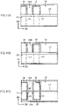
- a conductive layer 20 is formed on the surface of the mother substrate 2.
- the conductive layer 20 is formed of, for example, gold, platinum, palladium, nickel, or carbon and has a thickness of 0.001 to 100 ⁇ m.
- the formation of the conductive layer 20 is performed by, for example, screen printing, CVD, sputtering, or deposition.
- plural separation slits 21 extending in a direction of D2 are formed on the conductive layer 20.
- the conductive layer 20 has plural band-shape electrodes 20A and 20B insulated from each other.
- These slits 21 are formed to have a width of 10 to 300 ⁇ m by scanning laser light along a predetermined path, for example, using a laser oscillator 22.
- the laser oscillator 22 may include, for example, a CO 2 laser oscillator or a YAG laser oscillator, capable of oscillating laser light having a wavelength that can be easily absorbed by the conductive layer 20 and hardly absorbed by the mother substrate 2.
- a process of forming the conductive layer 20 and a process of forming the slits 21 are not necessarily performed in a separate manner, but may be performed in a collective manner, for example, using a predetermined mask by simultaneously forming the conductive layer 20 and the slits 21 to provide plural band-shape electrodes 20A and 20B.
- slits 23A and 23B for controlling an effective area of the reactive electrode 14A are formed.
- Such slits 23A and 23B are formed to have main lines 23Aa and 23Ba and subsidiary lines 23Ab and 23Bb, for example, using a laser oscillator 22.
- the main lines 23Aa and 23Ba extend in a direction of D1, and have a length corresponding to, for example, 50 to 98% of the widths of band-shape electrodes 20A and 20B.
- the distance between the main lines 23Aa and 23Ba is set to, for example, 30 to 98% of the distance between a pair of spacers 24A and 24B which will be described below.
- the subsidiary lines 23Ab and 23Bb extend in a direction of D2, in which the slit 23A has a U-shape as a whole, and the slit 23B has a rectangular shape as a whole.
- the shapes of the slits 23A and 23B may be variously changed, for example, such that the slit 23A has a rectangular shape, and the slit 23B has a U-shape.
- both of the slits 23A and 23B may have a U-shape, or both of the slits 23A and 23B may have a rectangular shape.
- plural spacers 24A and 24B are attached to extend in a direction of D1 perpendicular to plural separation slits 21.
- Such spacers 24A and 24B are attached farther than the distance between the main lines 23Aa and 23Ba such that the main lines 23Aa and 23Ba of the slits 23A and 23B for controlling the effective area of the reactive electrode 14A are exposed.
- the spacers 24A and 24B are arranged such that edges of the spacers 24A and 24B traverse the subsidiary lines 23Ab and 23Bb of the slits 23A and 23B.
- the spacers 24A and 24B may include, for example, a double-face adhesive tape or a hot-melt film.
- the width and the thickness of each of the spacers 24A and 24B are set to, for example, 1 to 20 mm and 20 to 300 ⁇ m, respectively.
- the distance between the spacers 24A and 24B is set to, for example, 100 to 3000 ⁇ m.
- a reagent solution is applied between the spacers 24A and 24B, for example, using a dispenser 25 known in the art.
- a reagent solution includes a liquid-phase or slurry-phase material containing an oxidoreductase and an electron carrier material.
- the oxidoreductase is selected depending on the type of the analysis target component within the specimen. For example, when a biosensor 1 appropriate to analyze glucose is formed, glucose oxidase (GOD) or glucose dehydrogenase (GDH) is used.
- the electron carrier material includes, for example, a ruthenium complex or an iron complex, and typically, [Ru(NH 3 ) 6 ]Cl 3 or K 3 [Fe(CN) 6 ].
- a sensor assembly 3 is obtained by attaching the cover 26 so as to bridge the spacers 24A and 24B.
- the cover 26 may be formed of, for example, the same material as that of the mother substrate 2 such as thermoplastic resin or PET having a high wettability such as vinylon or high-crystalline PVA.
- biosensors 1 can be obtained by cutting the sensor assembly 3 along a predetermined cutting line.
- the cutting of the sensor assembly 3 is performed using, for example, a diamond cutter.
- the effective area of the reactive electrode 14A is not controlled by the opening of the insulating layer which covers the electrodes 14 and 15, it is unnecessary to form the insulating layer in order to control the area of the electron transfer surface of the reactive electrode 14A. Therefore, it is possible to control the area of the electron transfer surface of the reactive electrode 14A in a simple, easy, and inexpensive manner without complicating the manufacturing processes or equipments.
- the slits 23A and 23B, and the laser oscillator 22 are used to control the area of the electron transfer surface of the reactive electrode 14A when plural separation slits 21 are formed in the conductive layer 20 using the laser oscillator 22, it unnecessary to prepare special equipment in order to form the slits 23A and 23B. Therefore, in this regard, it is possible to improve the measurement accuracy of the biosensor 1 by controlling the area of the electrode transfer surface of the reactive electrode 14A in a simple, easy, and inexpensive manner.
- the present invention is not limited to the aforementioned embodiments, but may be modified in various manners, for example, as shown in Figs. 11A and 11C .
- the slits 18 and 19 for controlling the effective area of the reactive electrode 14A are formed in an L-shape and a U-shape, respectively, by omitting one of the subsidiary lines in the slits 18 and 19.
- the slit 18 for controlling the effective area of the reactive electrode 14A is formed in an I-shape by omitting the subsidiary lines, and the slit 19 is formed in a U-shape by omitting one of the subsidiary lines.
- the slits 18 and 19 for controlling the effective area of the reactive electrode 14A are formed in an L-shape and a U-shape by omitting one of the subsidiary lines and, the slits 18' and 19' are also formed in the counter electrode 15A.
- the slits 18 and 19 and the slits 18' and 19' are symmetrically arranged with respect to the separation slit 17.
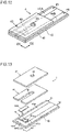
- the biosensor 4 shown in Figs. 12 to 14 is formed by stacking the substrate 40, the spacer 41, and the cover 42 in a similar way to that of the biosensor 1 described above (refer to Figs. 1 to 3 ).
- Electrodes 43 and 44 are formed on the substrate 40.
- the electrodes 43 and 44 have bending portions 43A and 44A extending in a direction of D1 and lead portions 43B and 44B extending in a direction of D2.
- the bending portions 43A and 44A are arranged in parallel in a direction of D2, and include an reactive electrode 43Aa and the counter electrode 44Aa defined by the spacer 41.
- slits 45 and 46 are formed in the bending portion 43A.
- Such slits 45 and 46 are provided to define the area (the effective area) of the electron transfer surface of the reactive electrode 43Aa. Similar to the slits 18 and 19 of the aforementioned biosensor 1 (refer to Figs. 3 and 4 ), the slits 45 and 46 include main lines 45A and 46A and subsidiary lines 45B and 46B.
- the main lines 45A and 46A extend in a direction of D2, and their lengths are set to, for example, 50 to 98% of the width of the bending portion 43A.
- the distance between the main lines 45A and 46A is set to, for example, 30 to 98% of the width of the slit in the spacer 41 which will be described below.
- the subsidiary lines 45B and 46B extend in a direction of D1
- the slit 45 is formed in a U-shape
- the slit 46 is formed in a rectangular shape.
- the spacer 41 is provided to define the distance from the surface of the substrate 40 to the lower surface of the cover 42, i.e., the height of the capillary 48, and has a slit 47.
- the slit 47 defines the width of the capillary 48 for introducing the specimen and the area of the portion (the reactive electrode 43 Aa and the counter electrode 44Aa) exposed within the capillary 48 in the electrodes 43 and 44.
- the spacer 41 is arranged such that the edge of the slit 47 extending in a direction of D2 traverses the subsidiary lines 45B and 46B of the slits 45 and 46.
- the capillary 48 is provided to move the introduced specimen such as blood in a longitudinal direction D2 of the substrate 40 using a capillary action and maintain the introduced specimen.
- the reagent layer 48A is formed to cover at least the reactive electrode 43Aa.
- Such a spacer 41 is configured of, for example, a double-face adhesive tape or a hot-melt film.
- the cover 42 is provided to define the capillary 13 in association with the spacer 41 or the like, and has a thru-hole 49.
- the cover 42 is formed of the same material as that of the substrate 40 such as thermoplastic resin or PET having a high wettability such as vinylon or high-crystalline PVA.
- the effective area of the reactive electrode 43Aa is defined by the slits 45 and 46, a deviation in the area of the reactive electrode 43Aa is suppressed. Therefore, it is possible to suppress a deviation in the sensor sensitivity of the biosensor 4 and perform the concentration measurement with excellent accuracy.
- the effective area of the reactive electrode 43Aa is not controlled by the opening of the insulating layer that covers the electrodes 44 and 45, it is unnecessary to form the insulating layer in order to control the area of the reactive electrode 43Aa. Therefore, it is possible to control the area of the reactive electrode 43Aa in a simple, easy, and inexpensive manner without complicating the manufacturing processes or equipments.
- the shapes of the slits 45 and 46 or the biosensor 4 may be variously modified as described in conjunction with the aforementioned biosensor 1 (refer to Figs. 3 and 4 ), for example, as shown in Figs. 11A to 11C .
- the present invention is also applicable to the biosensor obtained by omitting the covers 12 and 42.
- the effect obtained when the slit for controlling the effective area of the reactive electrode is provided was evaluated based on a deviation in the area of the reactive electrode.
- the electrode of the biosensor was formed to have a width of 0.85 mm and a length of 30 mm by sputtering nickel as a conductive layer on a PET substrate and forming a separation slit having a width of 150 ⁇ m using a laser oscillator.
- the slit for controlling the effective area of the reactive electrode was formed in a U-shape and a rectangular shape having a width of 150 ⁇ m using a laser oscillator in a similar way to the case where the separation slit is formed.
- the length was set to 0.65 mm, and the distance was set to 0.65 mm.
- the shortest distance between the subsidiary line and the cutting slit was set to 0.2 mm.
- the spacer is arranged such that the distance in a longitudinal direction of the substrate becomes 1.4 mm.
- the target effective area of the reactive electrode was set to 0.7 mm 2 .
- the target area of the reactive electrode was set to 1.2 mm 2 .
- the reagent layer containing [Ru(NH 3 )Cl 3 ] of 20 ⁇ g as an electron carrier material and glucose oxidase of 1 unit as the oxidoreductase for a single sensor was formed to cover the reactive electrode and the counter electrode.
- the area of the reactive electrode was measured by capturing an image of the reactive electrode using an image-capturing apparatus for the biosensor before the reagent layer and the cover are formed and processing the obtained image using measurement software known in the art.
- the result of the measurement for the area of the reactive electrode is shown in the following Table 1. [Table 1] No.
- the effect obtained when the slit for controlling the effective area of the reactive electrode is provided was evaluated based on deviations in the sensitivity of the sensor and the area of the reactive electrode.
- Example 1 As the biosensor, an original sensor and a comparison sensor were manufactured in a similar way to Example 1.
- the sensitivity of the biosensor was evaluated based on the response electric current value measured by supplying a specimen having a glucose concentration of 120 mg/dL to the biosensor.
- As the response electric current value a value obtained 5 seconds later after recognizing that the specimen is supplied to the biosensor was employed.
- the measurement results of the response electric current value are shown in the following Table 2 and Figs. 15A and 15B in association with the measurement results for the area of the reactive electrode. [Table 2] No.
- both of the S.D. and the C.V. are smaller, and a deviation in the area of the reactive electrode and a deviation in the response electric current value (sensitivity) are smaller in comparison with the comparison sample. Therefore, in the original sample having the slit for controlling the effective area of the reactive electrode, it is possible to form the reactive electrode in a targeted area with excellent accuracy and improve the measurement accuracy by suppressing a deviation in the output (response electric current value) of the sensor.
Claims (3)
- Procédé de fabrication d'un outil d'analyse, le procédé comprenant :un premier processus pour former une pluralité d'électrodes (20A, 20B) comprenant au moins une électrode réactive (20A) et une contre-électrode (20B) sur un substrat de base (2) ;un deuxième processus pour former un élément afin de définir une zone effective pour réaliser un transfert d'électrons au niveau d'au moins une de l'électrode réactive (20A) ou de la contre-électrode (20B) ;un troisième processus pour définir une zone de contact qui entre en contact avec un échantillon au niveau de l'électrode réactive (20A) par la fixation de plusieurs entretoises (24A, 24B) ; etl'application d'une solution de réactif entre les entretoises (24A, 24B),dans lequel le deuxième processus est réalisé en formant une pluralité de fentes (23A, 23B) dans l'électrode comprenant l'électrode réactive (20A),dans lequel chaque fente (23A, 23B) est formée pour avoir une ligne principale (23Aa, 23Ba) s'étendant dans une première direction (D1) dans laquelle l'électrode réactive (20A) et la contre-électrode (20B) sont alignées et une ligne auxiliaire (23Ab, 23Bb) s'étendant dans une seconde direction (D2) qui coupe la première direction (D1), etdans lequel les entretoises (24A, 24B) sont fixées de façon que les lignes principales (23Aa, 23Ba) des fentes (23A, 23B) sont exposées, et les entretoises (24A, 24B) sont fixées au-delà d'une distance entre les lignes principales (23Aa, 23Ba) des fentes (23A, 23B).
- Procédé selon la revendication 1, dans lequel le deuxième processus est réalisé en irradiant une lumière laser sur l'électrode.
- Procédé selon la revendication 2,
dans lequel le premier processus est réalisé en irradiant une lumière laser sur une couche conductrice (20) après que la couche conductrice (20) est formée sur le substrat de base (2).
Applications Claiming Priority (2)
| Application Number | Priority Date | Filing Date | Title |
|---|---|---|---|
| JP2007282781 | 2007-10-31 | ||
| PCT/JP2008/069981 WO2009057791A1 (fr) | 2007-10-31 | 2008-10-31 | Outil d'analyse et son procédé de fabrication |
Publications (3)
| Publication Number | Publication Date |
|---|---|
| EP2211172A1 EP2211172A1 (fr) | 2010-07-28 |
| EP2211172A4 EP2211172A4 (fr) | 2014-11-26 |
| EP2211172B1 true EP2211172B1 (fr) | 2022-03-30 |
Family
ID=40591170
Family Applications (1)
| Application Number | Title | Priority Date | Filing Date |
|---|---|---|---|
| EP08845459.0A Active EP2211172B1 (fr) | 2007-10-31 | 2008-10-31 | Procédé de fabrication d'un outil d'analyse |
Country Status (7)
| Country | Link |
|---|---|
| US (2) | US20100276285A1 (fr) |
| EP (1) | EP2211172B1 (fr) |
| JP (1) | JP5290985B2 (fr) |
| KR (1) | KR101450373B1 (fr) |
| CN (1) | CN101842697B (fr) |
| TW (1) | TWI460423B (fr) |
| WO (1) | WO2009057791A1 (fr) |
Families Citing this family (1)
| Publication number | Priority date | Publication date | Assignee | Title |
|---|---|---|---|---|
| US11073495B2 (en) | 2015-10-15 | 2021-07-27 | Arkray, Inc. | Biosensor and manufacturing method of biosensor |
Citations (1)
| Publication number | Priority date | Publication date | Assignee | Title |
|---|---|---|---|---|
| US6004441A (en) * | 1996-01-10 | 1999-12-21 | Matsushita Electric Industrial Co., Ltd. | Biosensor |
Family Cites Families (17)
| Publication number | Priority date | Publication date | Assignee | Title |
|---|---|---|---|---|
| US5320732A (en) * | 1990-07-20 | 1994-06-14 | Matsushita Electric Industrial Co., Ltd. | Biosensor and measuring apparatus using the same |
| US5437999A (en) * | 1994-02-22 | 1995-08-01 | Boehringer Mannheim Corporation | Electrochemical sensor |
| JP3259010B2 (ja) * | 1994-03-10 | 2002-02-18 | 独立行政法人産業技術総合研究所 | 酵素電極およびそれを使用する測定器 |
| US6241862B1 (en) * | 1996-02-14 | 2001-06-05 | Inverness Medical Technology, Inc. | Disposable test strips with integrated reagent/blood separation layer |
| JP3460183B2 (ja) * | 1996-12-24 | 2003-10-27 | 松下電器産業株式会社 | バイオセンサ |
| JPH10318969A (ja) | 1997-05-16 | 1998-12-04 | Nok Corp | バイオセンサ電極 |
| US6309526B1 (en) * | 1997-07-10 | 2001-10-30 | Matsushita Electric Industrial Co., Ltd. | Biosensor |
| BR9811609A (pt) * | 1997-09-05 | 2000-09-05 | Abbott Lab | Sensor eletroquìmico com áreas de elétrodo equalizadas |
| DE69937326T2 (de) * | 1998-04-02 | 2008-07-17 | Matsushita Electric Industrial Co., Ltd., Kadoma | Verfahren zur bestimmung eines substrates |
| US6821410B2 (en) * | 2001-03-07 | 2004-11-23 | Matsushita Electric Industrial Co., Ltd. | Biosensor and method of substrate quantification |
| EP2230508A1 (fr) | 2001-04-16 | 2010-09-22 | Panasonic Corporation | Biocapteur |
| US20070053790A1 (en) * | 2003-04-16 | 2007-03-08 | Arkray, Inc. | Analyzing tool being reduced in distance of diffusion of reagent and method for manufacture thereof |
| CN1453579A (zh) * | 2003-05-19 | 2003-11-05 | 浙江大学 | 血液乳酸电化学传感器 |
| US7294246B2 (en) | 2003-11-06 | 2007-11-13 | 3M Innovative Properties Company | Electrode for electrochemical sensors |
| US7741125B2 (en) * | 2004-02-04 | 2010-06-22 | Panasonic Corporation | Biosensor, biosensor measuring apparatus and measurement method |
| WO2007026683A1 (fr) * | 2005-09-02 | 2007-03-08 | Arkray, Inc. | Procédé pour détecter la condition de livraison d'un échantillon et analyseur |
| WO2008040997A1 (fr) * | 2006-10-05 | 2008-04-10 | Lifescan Scotland Limited | Bandelette réactive comprenant des électrodes à motifs |
-
2008
- 2008-10-31 WO PCT/JP2008/069981 patent/WO2009057791A1/fr active Application Filing
- 2008-10-31 TW TW097142309A patent/TWI460423B/zh active
- 2008-10-31 EP EP08845459.0A patent/EP2211172B1/fr active Active
- 2008-10-31 KR KR1020107011818A patent/KR101450373B1/ko active IP Right Grant
- 2008-10-31 JP JP2009539150A patent/JP5290985B2/ja active Active
- 2008-10-31 CN CN200880113705.7A patent/CN101842697B/zh active Active
- 2008-10-31 US US12/740,834 patent/US20100276285A1/en not_active Abandoned
-
2014
- 2014-03-04 US US14/195,994 patent/US9063077B2/en active Active
Patent Citations (1)
| Publication number | Priority date | Publication date | Assignee | Title |
|---|---|---|---|---|
| US6004441A (en) * | 1996-01-10 | 1999-12-21 | Matsushita Electric Industrial Co., Ltd. | Biosensor |
Also Published As
| Publication number | Publication date |
|---|---|
| US9063077B2 (en) | 2015-06-23 |
| TW200931012A (en) | 2009-07-16 |
| JP5290985B2 (ja) | 2013-09-18 |
| KR20100103481A (ko) | 2010-09-27 |
| JPWO2009057791A1 (ja) | 2011-03-10 |
| US20100276285A1 (en) | 2010-11-04 |
| CN101842697A (zh) | 2010-09-22 |
| WO2009057791A1 (fr) | 2009-05-07 |
| US20140186548A1 (en) | 2014-07-03 |
| TWI460423B (zh) | 2014-11-11 |
| EP2211172A4 (fr) | 2014-11-26 |
| KR101450373B1 (ko) | 2014-10-14 |
| EP2211172A1 (fr) | 2010-07-28 |
| CN101842697B (zh) | 2016-06-15 |
Similar Documents
| Publication | Publication Date | Title |
|---|---|---|
| KR100874630B1 (ko) | 바이오센서 및 관련된 응용분야를 참고한 그 제조방법 | |
| AU2010212483B2 (en) | Electrochemical cell and method of making an electrochemical cell | |
| JP2009505102A (ja) | テストストリップの製造方法及びテストパターンの分析方法 | |
| CN102735722A (zh) | 生物感测试纸及其制造方法以及其电极图案的制造方法 | |
| EP1971460B1 (fr) | Procede de formation d'un capteur test multicouche | |
| US8399070B2 (en) | Method of defining electrodes using laser-ablation and dielectric material | |
| EP2211172B1 (fr) | Procédé de fabrication d'un outil d'analyse | |
| US7906000B2 (en) | Analyzer and method of manufacturing the same | |
| JP2009019935A (ja) | 分析用具の製造方法 | |
| CN115586058A (zh) | 生物传感器 | |
| AU2013204851B2 (en) | Electrochemical cell and method of making an electrochemical cell |
Legal Events
| Date | Code | Title | Description |
|---|---|---|---|
| PUAI | Public reference made under article 153(3) epc to a published international application that has entered the european phase |
Free format text: ORIGINAL CODE: 0009012 |
|
| 17P | Request for examination filed |
Effective date: 20100519 |
|
| AK | Designated contracting states |
Kind code of ref document: A1 Designated state(s): AT BE BG CH CY CZ DE DK EE ES FI FR GB GR HR HU IE IS IT LI LT LU LV MC MT NL NO PL PT RO SE SI SK TR |
|
| AX | Request for extension of the european patent |
Extension state: AL BA MK RS |
|
| DAX | Request for extension of the european patent (deleted) | ||
| A4 | Supplementary search report drawn up and despatched |
Effective date: 20141029 |
|
| RIC1 | Information provided on ipc code assigned before grant |
Ipc: G01N 27/327 20060101AFI20141023BHEP |
|
| RIN1 | Information on inventor provided before grant (corrected) |
Inventor name: FUJII, TOMOHIRO Inventor name: KUSAKA, YASUHIDE |
|
| STAA | Information on the status of an ep patent application or granted ep patent |
Free format text: STATUS: EXAMINATION IS IN PROGRESS |
|
| 17Q | First examination report despatched |
Effective date: 20180405 |
|
| STAA | Information on the status of an ep patent application or granted ep patent |
Free format text: STATUS: EXAMINATION IS IN PROGRESS |
|
| STAA | Information on the status of an ep patent application or granted ep patent |
Free format text: STATUS: EXAMINATION IS IN PROGRESS |
|
| GRAP | Despatch of communication of intention to grant a patent |
Free format text: ORIGINAL CODE: EPIDOSNIGR1 |
|
| STAA | Information on the status of an ep patent application or granted ep patent |
Free format text: STATUS: GRANT OF PATENT IS INTENDED |
|
| INTG | Intention to grant announced |
Effective date: 20220114 |
|
| GRAS | Grant fee paid |
Free format text: ORIGINAL CODE: EPIDOSNIGR3 |
|
| GRAA | (expected) grant |
Free format text: ORIGINAL CODE: 0009210 |
|
| STAA | Information on the status of an ep patent application or granted ep patent |
Free format text: STATUS: THE PATENT HAS BEEN GRANTED |
|
| AK | Designated contracting states |
Kind code of ref document: B1 Designated state(s): AT BE BG CH CY CZ DE DK EE ES FI FR GB GR HR HU IE IS IT LI LT LU LV MC MT NL NO PL PT RO SE SI SK TR |
|
| REG | Reference to a national code |
Ref country code: GB Ref legal event code: FG4D |
|
| REG | Reference to a national code |
Ref country code: CH Ref legal event code: EP |
|
| REG | Reference to a national code |
Ref country code: AT Ref legal event code: REF Ref document number: 1479651 Country of ref document: AT Kind code of ref document: T Effective date: 20220415 |
|
| REG | Reference to a national code |
Ref country code: DE Ref legal event code: R096 Ref document number: 602008064450 Country of ref document: DE |
|
| REG | Reference to a national code |
Ref country code: IE Ref legal event code: FG4D |
|
| REG | Reference to a national code |
Ref country code: LT Ref legal event code: MG9D |
|
| PG25 | Lapsed in a contracting state [announced via postgrant information from national office to epo] |
Ref country code: SE Free format text: LAPSE BECAUSE OF FAILURE TO SUBMIT A TRANSLATION OF THE DESCRIPTION OR TO PAY THE FEE WITHIN THE PRESCRIBED TIME-LIMIT Effective date: 20220330 Ref country code: NO Free format text: LAPSE BECAUSE OF FAILURE TO SUBMIT A TRANSLATION OF THE DESCRIPTION OR TO PAY THE FEE WITHIN THE PRESCRIBED TIME-LIMIT Effective date: 20220630 Ref country code: LT Free format text: LAPSE BECAUSE OF FAILURE TO SUBMIT A TRANSLATION OF THE DESCRIPTION OR TO PAY THE FEE WITHIN THE PRESCRIBED TIME-LIMIT Effective date: 20220330 Ref country code: HR Free format text: LAPSE BECAUSE OF FAILURE TO SUBMIT A TRANSLATION OF THE DESCRIPTION OR TO PAY THE FEE WITHIN THE PRESCRIBED TIME-LIMIT Effective date: 20220330 Ref country code: BG Free format text: LAPSE BECAUSE OF FAILURE TO SUBMIT A TRANSLATION OF THE DESCRIPTION OR TO PAY THE FEE WITHIN THE PRESCRIBED TIME-LIMIT Effective date: 20220630 |
|
| REG | Reference to a national code |
Ref country code: NL Ref legal event code: MP Effective date: 20220330 |
|
| REG | Reference to a national code |
Ref country code: AT Ref legal event code: MK05 Ref document number: 1479651 Country of ref document: AT Kind code of ref document: T Effective date: 20220330 |
|
| PG25 | Lapsed in a contracting state [announced via postgrant information from national office to epo] |
Ref country code: LV Free format text: LAPSE BECAUSE OF FAILURE TO SUBMIT A TRANSLATION OF THE DESCRIPTION OR TO PAY THE FEE WITHIN THE PRESCRIBED TIME-LIMIT Effective date: 20220330 Ref country code: GR Free format text: LAPSE BECAUSE OF FAILURE TO SUBMIT A TRANSLATION OF THE DESCRIPTION OR TO PAY THE FEE WITHIN THE PRESCRIBED TIME-LIMIT Effective date: 20220701 Ref country code: FI Free format text: LAPSE BECAUSE OF FAILURE TO SUBMIT A TRANSLATION OF THE DESCRIPTION OR TO PAY THE FEE WITHIN THE PRESCRIBED TIME-LIMIT Effective date: 20220330 |
|
| PG25 | Lapsed in a contracting state [announced via postgrant information from national office to epo] |
Ref country code: NL Free format text: LAPSE BECAUSE OF FAILURE TO SUBMIT A TRANSLATION OF THE DESCRIPTION OR TO PAY THE FEE WITHIN THE PRESCRIBED TIME-LIMIT Effective date: 20220330 |
|
| PG25 | Lapsed in a contracting state [announced via postgrant information from national office to epo] |
Ref country code: RO Free format text: LAPSE BECAUSE OF FAILURE TO SUBMIT A TRANSLATION OF THE DESCRIPTION OR TO PAY THE FEE WITHIN THE PRESCRIBED TIME-LIMIT Effective date: 20220330 Ref country code: PT Free format text: LAPSE BECAUSE OF FAILURE TO SUBMIT A TRANSLATION OF THE DESCRIPTION OR TO PAY THE FEE WITHIN THE PRESCRIBED TIME-LIMIT Effective date: 20220801 Ref country code: ES Free format text: LAPSE BECAUSE OF FAILURE TO SUBMIT A TRANSLATION OF THE DESCRIPTION OR TO PAY THE FEE WITHIN THE PRESCRIBED TIME-LIMIT Effective date: 20220330 Ref country code: EE Free format text: LAPSE BECAUSE OF FAILURE TO SUBMIT A TRANSLATION OF THE DESCRIPTION OR TO PAY THE FEE WITHIN THE PRESCRIBED TIME-LIMIT Effective date: 20220330 Ref country code: CZ Free format text: LAPSE BECAUSE OF FAILURE TO SUBMIT A TRANSLATION OF THE DESCRIPTION OR TO PAY THE FEE WITHIN THE PRESCRIBED TIME-LIMIT Effective date: 20220330 Ref country code: AT Free format text: LAPSE BECAUSE OF FAILURE TO SUBMIT A TRANSLATION OF THE DESCRIPTION OR TO PAY THE FEE WITHIN THE PRESCRIBED TIME-LIMIT Effective date: 20220330 |
|
| PG25 | Lapsed in a contracting state [announced via postgrant information from national office to epo] |
Ref country code: PL Free format text: LAPSE BECAUSE OF FAILURE TO SUBMIT A TRANSLATION OF THE DESCRIPTION OR TO PAY THE FEE WITHIN THE PRESCRIBED TIME-LIMIT Effective date: 20220330 Ref country code: IS Free format text: LAPSE BECAUSE OF FAILURE TO SUBMIT A TRANSLATION OF THE DESCRIPTION OR TO PAY THE FEE WITHIN THE PRESCRIBED TIME-LIMIT Effective date: 20220730 |
|
| REG | Reference to a national code |
Ref country code: DE Ref legal event code: R097 Ref document number: 602008064450 Country of ref document: DE |
|
| PG25 | Lapsed in a contracting state [announced via postgrant information from national office to epo] |
Ref country code: DK Free format text: LAPSE BECAUSE OF FAILURE TO SUBMIT A TRANSLATION OF THE DESCRIPTION OR TO PAY THE FEE WITHIN THE PRESCRIBED TIME-LIMIT Effective date: 20220330 |
|
| PLBE | No opposition filed within time limit |
Free format text: ORIGINAL CODE: 0009261 |
|
| STAA | Information on the status of an ep patent application or granted ep patent |
Free format text: STATUS: NO OPPOSITION FILED WITHIN TIME LIMIT |
|
| 26N | No opposition filed |
Effective date: 20230103 |
|
| PG25 | Lapsed in a contracting state [announced via postgrant information from national office to epo] |
Ref country code: SI Free format text: LAPSE BECAUSE OF FAILURE TO SUBMIT A TRANSLATION OF THE DESCRIPTION OR TO PAY THE FEE WITHIN THE PRESCRIBED TIME-LIMIT Effective date: 20220330 Ref country code: MC Free format text: LAPSE BECAUSE OF FAILURE TO SUBMIT A TRANSLATION OF THE DESCRIPTION OR TO PAY THE FEE WITHIN THE PRESCRIBED TIME-LIMIT Effective date: 20220330 |
|
| REG | Reference to a national code |
Ref country code: CH Ref legal event code: PL |
|
| REG | Reference to a national code |
Ref country code: BE Ref legal event code: MM Effective date: 20221031 |
|
| PG25 | Lapsed in a contracting state [announced via postgrant information from national office to epo] |
Ref country code: LU Free format text: LAPSE BECAUSE OF NON-PAYMENT OF DUE FEES Effective date: 20221031 |
|
| PG25 | Lapsed in a contracting state [announced via postgrant information from national office to epo] |
Ref country code: LI Free format text: LAPSE BECAUSE OF NON-PAYMENT OF DUE FEES Effective date: 20221031 Ref country code: CH Free format text: LAPSE BECAUSE OF NON-PAYMENT OF DUE FEES Effective date: 20221031 |
|
| PG25 | Lapsed in a contracting state [announced via postgrant information from national office to epo] |
Ref country code: BE Free format text: LAPSE BECAUSE OF NON-PAYMENT OF DUE FEES Effective date: 20221031 |
|
| PG25 | Lapsed in a contracting state [announced via postgrant information from national office to epo] |
Ref country code: IE Free format text: LAPSE BECAUSE OF NON-PAYMENT OF DUE FEES Effective date: 20221031 |
|
| PGFP | Annual fee paid to national office [announced via postgrant information from national office to epo] |
Ref country code: GB Payment date: 20231020 Year of fee payment: 16 |
|
| PGFP | Annual fee paid to national office [announced via postgrant information from national office to epo] |
Ref country code: IT Payment date: 20231026 Year of fee payment: 16 Ref country code: FR Payment date: 20231024 Year of fee payment: 16 Ref country code: DE Payment date: 20231020 Year of fee payment: 16 |
|
| PG25 | Lapsed in a contracting state [announced via postgrant information from national office to epo] |
Ref country code: HU Free format text: LAPSE BECAUSE OF FAILURE TO SUBMIT A TRANSLATION OF THE DESCRIPTION OR TO PAY THE FEE WITHIN THE PRESCRIBED TIME-LIMIT; INVALID AB INITIO Effective date: 20081031 |
|
| PG25 | Lapsed in a contracting state [announced via postgrant information from national office to epo] |
Ref country code: CY Free format text: LAPSE BECAUSE OF FAILURE TO SUBMIT A TRANSLATION OF THE DESCRIPTION OR TO PAY THE FEE WITHIN THE PRESCRIBED TIME-LIMIT Effective date: 20220330 |