EP2210820A1 - Container - Google Patents
Container Download PDFInfo
- Publication number
- EP2210820A1 EP2210820A1 EP10158295A EP10158295A EP2210820A1 EP 2210820 A1 EP2210820 A1 EP 2210820A1 EP 10158295 A EP10158295 A EP 10158295A EP 10158295 A EP10158295 A EP 10158295A EP 2210820 A1 EP2210820 A1 EP 2210820A1
- Authority
- EP
- European Patent Office
- Prior art keywords
- container
- salt
- spout
- gate
- mouth
- Prior art date
- Legal status (The legal status is an assumption and is not a legal conclusion. Google has not performed a legal analysis and makes no representation as to the accuracy of the status listed.)
- Withdrawn
Links
Images




Classifications
-
- B—PERFORMING OPERATIONS; TRANSPORTING
- B65—CONVEYING; PACKING; STORING; HANDLING THIN OR FILAMENTARY MATERIAL
- B65D—CONTAINERS FOR STORAGE OR TRANSPORT OF ARTICLES OR MATERIALS, e.g. BAGS, BARRELS, BOTTLES, BOXES, CANS, CARTONS, CRATES, DRUMS, JARS, TANKS, HOPPERS, FORWARDING CONTAINERS; ACCESSORIES, CLOSURES, OR FITTINGS THEREFOR; PACKAGING ELEMENTS; PACKAGES
- B65D51/00—Closures not otherwise provided for
- B65D51/18—Arrangements of closures with protective outer cap-like covers or of two or more co-operating closures
- B65D51/20—Caps, lids, or covers co-operating with an inner closure arranged to be opened by piercing, cutting, or tearing
- B65D51/22—Caps, lids, or covers co-operating with an inner closure arranged to be opened by piercing, cutting, or tearing having means for piercing, cutting, or tearing the inner closure
- B65D51/221—Caps, lids, or covers co-operating with an inner closure arranged to be opened by piercing, cutting, or tearing having means for piercing, cutting, or tearing the inner closure a major part of the inner closure being left inside the container after the opening
- B65D51/222—Caps, lids, or covers co-operating with an inner closure arranged to be opened by piercing, cutting, or tearing having means for piercing, cutting, or tearing the inner closure a major part of the inner closure being left inside the container after the opening the piercing or cutting means being integral with, or fixedly attached to, the outer closure
-
- B—PERFORMING OPERATIONS; TRANSPORTING
- B65—CONVEYING; PACKING; STORING; HANDLING THIN OR FILAMENTARY MATERIAL
- B65D—CONTAINERS FOR STORAGE OR TRANSPORT OF ARTICLES OR MATERIALS, e.g. BAGS, BARRELS, BOTTLES, BOXES, CANS, CARTONS, CRATES, DRUMS, JARS, TANKS, HOPPERS, FORWARDING CONTAINERS; ACCESSORIES, CLOSURES, OR FITTINGS THEREFOR; PACKAGING ELEMENTS; PACKAGES
- B65D47/00—Closures with filling and discharging, or with discharging, devices
- B65D47/04—Closures with discharging devices other than pumps
- B65D47/20—Closures with discharging devices other than pumps comprising hand-operated members for controlling discharge
- B65D47/26—Closures with discharging devices other than pumps comprising hand-operated members for controlling discharge with slide valves, i.e. valves that open and close a passageway by sliding over a port, e.g. formed with slidable spouts
- B65D47/28—Closures with discharging devices other than pumps comprising hand-operated members for controlling discharge with slide valves, i.e. valves that open and close a passageway by sliding over a port, e.g. formed with slidable spouts having linear movement
- B65D47/286—Closures with discharging devices other than pumps comprising hand-operated members for controlling discharge with slide valves, i.e. valves that open and close a passageway by sliding over a port, e.g. formed with slidable spouts having linear movement between planar parts
-
- B—PERFORMING OPERATIONS; TRANSPORTING
- B65—CONVEYING; PACKING; STORING; HANDLING THIN OR FILAMENTARY MATERIAL
- B65D—CONTAINERS FOR STORAGE OR TRANSPORT OF ARTICLES OR MATERIALS, e.g. BAGS, BARRELS, BOTTLES, BOXES, CANS, CARTONS, CRATES, DRUMS, JARS, TANKS, HOPPERS, FORWARDING CONTAINERS; ACCESSORIES, CLOSURES, OR FITTINGS THEREFOR; PACKAGING ELEMENTS; PACKAGES
- B65D5/00—Rigid or semi-rigid containers of polygonal cross-section, e.g. boxes, cartons or trays, formed by folding or erecting one or more blanks made of paper
- B65D5/42—Details of containers or of foldable or erectable container blanks
- B65D5/72—Contents-dispensing means
- B65D5/721—Contents-dispensing means consisting of mobile elements forming part of the containers or attached to the containers
- B65D5/723—Sliding elements for covering and uncovering discharge openings of containers, e.g. slide-closures
-
- B—PERFORMING OPERATIONS; TRANSPORTING
- B65—CONVEYING; PACKING; STORING; HANDLING THIN OR FILAMENTARY MATERIAL
- B65D—CONTAINERS FOR STORAGE OR TRANSPORT OF ARTICLES OR MATERIALS, e.g. BAGS, BARRELS, BOTTLES, BOXES, CANS, CARTONS, CRATES, DRUMS, JARS, TANKS, HOPPERS, FORWARDING CONTAINERS; ACCESSORIES, CLOSURES, OR FITTINGS THEREFOR; PACKAGING ELEMENTS; PACKAGES
- B65D5/00—Rigid or semi-rigid containers of polygonal cross-section, e.g. boxes, cartons or trays, formed by folding or erecting one or more blanks made of paper
- B65D5/42—Details of containers or of foldable or erectable container blanks
- B65D5/72—Contents-dispensing means
- B65D5/728—Contents-dispensing means for drawer-and-shell-type containers
-
- B—PERFORMING OPERATIONS; TRANSPORTING
- B65—CONVEYING; PACKING; STORING; HANDLING THIN OR FILAMENTARY MATERIAL
- B65D—CONTAINERS FOR STORAGE OR TRANSPORT OF ARTICLES OR MATERIALS, e.g. BAGS, BARRELS, BOTTLES, BOXES, CANS, CARTONS, CRATES, DRUMS, JARS, TANKS, HOPPERS, FORWARDING CONTAINERS; ACCESSORIES, CLOSURES, OR FITTINGS THEREFOR; PACKAGING ELEMENTS; PACKAGES
- B65D83/00—Containers or packages with special means for dispensing contents
- B65D83/06—Containers or packages with special means for dispensing contents for dispensing powdered or granular material
Definitions
- the present invention relates to a container which contains regenerating salt for dishwashers.
- Most dishwashers are equipped with a tank for regenerating salt.
- the filling of the salt tank is usually carried out on a regular but infrequent basis and is troublesome for a dishwasher user.
- the filling of the salt tank is generally done with the aid of a funnel.
- One such device is described in DE-A-42 14 147 .
- this device may overcome some of the issues associated with the filling of the salt tank its use is not without problems.
- the user When using this device the user is required to fill the funnel with salt and then to place the device on the mouth of salt tank of the dishwasher. A gate is then operated to release the salt. Not only is it difficult to fill the funnel without spilling salt but also it is difficult to avoid spilling salt when locating the device on the mouth of the salt tank. Furthermore the user has to gauge how much salt to add to the funnel: if the amount is incorrectly gauged then the funnel must be removed when partially full of salt leading to more spillage or in the case of insufficient filling the entire operation must be repeated, again causing more spillage.
- EP 0 947 157 Al describes a similar device. This device comprises two chambers; a first chamber engages the outer periphery of the mouth of the salt tank and being connected to a second chamber (which contains the salt) via a moveable gate.
- EP0778223 also describes a container for detergent.
- This device also has some disadvantageous properties, suffering principally as a result of the design of the device with a significant amount of residual salt being left in the first chamber thereof. This residue is spilled when the device is pulled away from the mouth of the salt tank.
- the device suffers from a poor flow of salt. It is thought that when the salt tank of the dishwasher fills with salt, residual water contained in the salt tank enters the container. This water wets the salt before its entry in the tank makes it adhere to the wall of the first chamber of the device, disturbing the flow. In severe cases the presence of this water can actually block the flow of salt altogether requiring that a user shakes the device with a much greater risk of salt spillage.
- a device described in FR-A 2 807 641 attempts to address some of the problems of this device. However, it still has a two chamber arrangement and thus still suffers from residue deposition. Additionally it still suffers from the problem of water ingress and its effect of the flow of salt.
- a container which contains regenerating salt for a dishwasher, the container comprising a body having a spout adapted to engage an inner periphery of a mouth of a dishwasher salt tank, the spout having a gate operable by a user to allow the flow of salt, wherein in use the spout engages an inner channel (such as the innermost channel of the mouth of the salt tank).
- the spout engages the mouth such that the leading edge of the spout projects into the channel.
- the spout is self-supporting, namely the spout is capable of supporting the entire body when engaged with the opening of the salt tank without the need for any other external support.
- the gate may be operated by a user before the container is placed into engagement with the mouth of the salt tank.
- the gate may be operated after the container has been placed into engagement with the mouth of the salt tank (in this case an even greater reduction of spillage can be achieved).
- the container in accordance with the invention has been found to have excellent properties, providing a previously un-enjoyed heightened sense of convenience to the consumer.
- the container allows for spillage free rapid and convenient filling of the salt tank with none of the problems of the devices of the prior art.
- the container holds a sufficient amount of salt to recharge a typical dishwasher salt tank.
- the container is a "single use” item in that the consumer uses the container of the present invention to completely recharge the salt tank of the dishwasher when necessary (e.g. as indicated to do so by a warning light / buzzer on the machine or by the height of a floater in the salt tank) and once used the container may be discarded.
- the gate is preferably in the form of a sheet / cap that blocks the spout of the container to prevent salt discharge in storage / transport.
- the gate is associated with a handle that may be operated by a user.
- the handle comprises a flap and the gate is operated by a pulling motion, wherein the pulling motion tears the gate from the spout thus letting the salt run into the salt tank.
- the gate when in the form of a sheet, may be disrupted / pierced when the container is placed into engagement with the mouth of the salt tank.
- the piercing means may comprise a cap arranged around the end of the spout, the cap being pushed back into the sheet on engagement with the mouth of the salt tank. Normally the cap has a removable blocking means to prevent unintentional movement before engagement with the mouth.
- the gate may comprise a valve which is operated by a user.
- a preferred form of valve is a multi-component device, wherein the valve has a portion which engages the mouth of the salt tank and a portion which is attached to the spout of the container.
- the portions of the valve preferably each have a discharge aperture which when aligned allow the discharge of salt. The alignment may be achieved by rotation or other movement, e.g. translation movement of the container.
- the gate may comprise a plurality of separate components operated / removed in different ways.
- the gate may comprise a cap which covers the spout and a sheet / block of material underneath the cap.
- the cap preferably covers the end of the spout and the sheet / block preferably blocks a portion of the spout.
- the sheet / block is most preferably water soluble / dispersible in water.
- the user removes the cap before placing the container into engagement with the mouth of the salt tank.
- the block dissolves / dissipates by contact with any residual water / moisture present in the salt tank. As the sheet / block dissolves / dissipates the salt is dispensed.
- the spout itself may comprise the gate.
- release of salt from the container may be achieved by movement of the spout relative to the container to create a flow passageway.
- the gate is one which is operated by the mechanical action of the user, to expose the spout and allow the flow of salt.
- the mechanical action may for example be by an action of tearing or sliding or turning or pulling or pushing or tilting or pivoting.
- the container according to the invention may be made out of one or more of a variety of materials such as paper, reinforced paper / card / cardboard, aluminium, plastics (e.g. PVC, polyethylene or polypropylene). Generally reinforced paper, cardboard, plastics, or an admixture thereof are preferred. It will be appreciated that different parts of the container may comprise different materials, e.g. the body of the container may comprise cardboard and the spout may comprise a plastics material.
- the container preferably comprises a simple geometric shape such as a cone, pyramid or an oblong / cube. Most preferably the shape tapers in the portion terminating in the spout. Clearly shapes such as cones and pyramids include tapering portions. Other shapes such as oblong preferably include an added tapering portion.
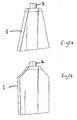
- Figure 1 shows a container 1 in the form of a pyramid.
- the container 1 has a removable gate 2 (removable by a tearing /pulling action).
- the removable gate 2 acts as a seal in storage / transport and is intended to be removed just before use, just before the exposed spout of the container (not shown) is engaged with an inner periphery of a mouth of a dishwasher salt tank.
- Figures 2a and 2b show a container 1.
- the container 1 is in the form of a truncated prism and in Figure 2b the container 1 is in the form of an irregular hexagon.
- the container has a spout 3.
- the spout 3 is usually sealed in storage / transport (seal not shown) with the seal being intended to be removed just before use. The spout can then be engaged with an inner periphery of a mouth of a dishwasher salt tank.
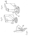
- Figures 3a to 3d shows a container 1 in the form of a truncated rectangle.
- the container 1 has a movable spout 3 (movable by a pulling action), which is mounted within the wall of the truncated portion.
- the wall of the truncated portion has an aperture 4.
- the spout 3 can be moved such that it is brought into alignment with the aperture 4 to allow discharge of the contents of the container.
- the spout 3 can be moved such that it is brought out of alignment with the aperture 4 so as not to allow discharge of the contents of the container and act a seal on the container.
- Figures 4a to 4c show a container 1 in the form of a rectangle.
- the container 1 has a movable spout 3 (movable by a pulling action), which is mounted adjacent a wall of the container.
- the wall of the container has an aperture 4.
- the spout 3 can be moved such that it is brought into alignment with the aperture 4 to allow discharge of the contents of the container.
- the spout 3 can be moved such that it is brought out of alignment with the aperture 4 so as not to allow discharge of the contents of the container and act a seal on the container.
- Figures 5a to 5c show a container 1 in the form of a bottle.
- the bottle 1 has a spout 3. Adjacent the spout 3 is a water soluble film (not shown). On insertion of the spout 3 of the container 1 into a mouth of a dishwasher salt tank any water present causes disruption of the water soluble film allowing discharge of the contents of the bottle 1.
- Figure 6 shows a container 1 in the form of a bottle.
- the bottle 1 has a spout 3.
- the spout 3 is opened to allow discharge of the contents of the bottle by a twisting motion to align flow channels within different portions of the spout 3.
- Figures 7a to 7c show a container 1 in the form of a bottle.
- the bottle 1 has a spout 3.
- Adjacent the spout 3 is a film 5.
- the film is disrupted to allow discharge of the contents of the container 1.
- Disruption is performed by moving a piercing member 6 arranged co-axially around the spout 3 down to the bottom of the bottle. In storage / transport the piercing member 6 is distanced from the film 5 by a removable retaining member 7.
- Figures 8a to 8c show a container 1 in the form of a bottle.
- the bottle 1 is in two portions 1a and 1b.
- the container 1 is weakened along the join between portions 1a and 1b to allow easy separation thereof.
- Portion 1a is in the form of a funnel having a spout 3.
- the portions of the container are separated with the portion 1a being placed into engagement with an inner periphery of a mouth of a dishwasher salt tank.
- the contents of the container 1 (which may be disposed inside a secondary packaging) can then be discharged through the funnel 1a.
Landscapes
- Engineering & Computer Science (AREA)
- Mechanical Engineering (AREA)
- Details Of Rigid Or Semi-Rigid Containers (AREA)
- Closures For Containers (AREA)
Abstract
Description
- The present invention relates to a container which contains regenerating salt for dishwashers.
- Most dishwashers are equipped with a tank for regenerating salt. The filling of the salt tank is usually carried out on a regular but infrequent basis and is troublesome for a dishwasher user.
- The filling of the salt tank is generally done with the aid of a funnel. One such device is described in
DE-A-42 14 147 . However, whilst this device may overcome some of the issues associated with the filling of the salt tank its use is not without problems. - When using this device the user is required to fill the funnel with salt and then to place the device on the mouth of salt tank of the dishwasher. A gate is then operated to release the salt. Not only is it difficult to fill the funnel without spilling salt but also it is difficult to avoid spilling salt when locating the device on the mouth of the salt tank. Furthermore the user has to gauge how much salt to add to the funnel: if the amount is incorrectly gauged then the funnel must be removed when partially full of salt leading to more spillage or in the case of insufficient filling the entire operation must be repeated, again causing more spillage.
- Indeed users are advised to run the machine whilst empty through a cycle to disperse the spilled salt.
-
EP 0 947 157 Al describes a similar device. This device comprises two chambers; a first chamber engages the outer periphery of the mouth of the salt tank and being connected to a second chamber (which contains the salt) via a moveable gate.EP0778223 also describes a container for detergent. - This device also has some disadvantageous properties, suffering principally as a result of the design of the device with a significant amount of residual salt being left in the first chamber thereof. This residue is spilled when the device is pulled away from the mouth of the salt tank.
- Additionally the device suffers from a poor flow of salt. It is thought that when the salt tank of the dishwasher fills with salt, residual water contained in the salt tank enters the container. This water wets the salt before its entry in the tank makes it adhere to the wall of the first chamber of the device, disturbing the flow. In severe cases the presence of this water can actually block the flow of salt altogether requiring that a user shakes the device with a much greater risk of salt spillage.
- A device described in
FR- A 2 807 641 - It is an object of the present invention to obviate / mitigate the problems outlined above.
- According to a first aspect of the present invention there is provided a container which contains regenerating salt for a dishwasher, the container comprising a body having a spout adapted to engage an inner periphery of a mouth of a dishwasher salt tank, the spout having a gate operable by a user to allow the flow of salt, wherein in use the spout engages an inner channel (such as the innermost channel of the mouth of the salt tank).
- Generally the spout engages the mouth such that the leading edge of the spout projects into the channel. Most preferably the spout is self-supporting, namely the spout is capable of supporting the entire body when engaged with the opening of the salt tank without the need for any other external support.
- The gate may be operated by a user before the container is placed into engagement with the mouth of the salt tank. Alternatively the gate may be operated after the container has been placed into engagement with the mouth of the salt tank (in this case an even greater reduction of spillage can be achieved).
- The container in accordance with the invention has been found to have excellent properties, providing a previously un-enjoyed heightened sense of convenience to the consumer.
- The container allows for spillage free rapid and convenient filling of the salt tank with none of the problems of the devices of the prior art.
- Preferably the container holds a sufficient amount of salt to recharge a typical dishwasher salt tank. Indeed in this regard it is most preferred that the container is a "single use" item in that the consumer uses the container of the present invention to completely recharge the salt tank of the dishwasher when necessary (e.g. as indicated to do so by a warning light / buzzer on the machine or by the height of a floater in the salt tank) and once used the container may be discarded.
- The gate is preferably in the form of a sheet / cap that blocks the spout of the container to prevent salt discharge in storage / transport. Generally the gate is associated with a handle that may be operated by a user. Most preferably the handle comprises a flap and the gate is operated by a pulling motion, wherein the pulling motion tears the gate from the spout thus letting the salt run into the salt tank. Optionally the gate, when in the form of a sheet, may be disrupted / pierced when the container is placed into engagement with the mouth of the salt tank. The piercing means may comprise a cap arranged around the end of the spout, the cap being pushed back into the sheet on engagement with the mouth of the salt tank. Normally the cap has a removable blocking means to prevent unintentional movement before engagement with the mouth.
- Alternatively the gate may comprise a valve which is operated by a user. A preferred form of valve is a multi-component device, wherein the valve has a portion which engages the mouth of the salt tank and a portion which is attached to the spout of the container. The portions of the valve preferably each have a discharge aperture which when aligned allow the discharge of salt. The alignment may be achieved by rotation or other movement, e.g. translation movement of the container.
- In a further alternative the gate may comprise a plurality of separate components operated / removed in different ways. As an example the gate may comprise a cap which covers the spout and a sheet / block of material underneath the cap. The cap preferably covers the end of the spout and the sheet / block preferably blocks a portion of the spout. The sheet / block is most preferably water soluble / dispersible in water. For this embodiment the user removes the cap before placing the container into engagement with the mouth of the salt tank. The block then dissolves / dissipates by contact with any residual water / moisture present in the salt tank. As the sheet / block dissolves / dissipates the salt is dispensed.
- In a yet further alternative the spout itself may comprise the gate. In this alternative release of salt from the container may be achieved by movement of the spout relative to the container to create a flow passageway.
- Preferably the gate is one which is operated by the mechanical action of the user, to expose the spout and allow the flow of salt. The mechanical action may for example be by an action of tearing or sliding or turning or pulling or pushing or tilting or pivoting.
- The container according to the invention may be made out of one or more of a variety of materials such as paper, reinforced paper / card / cardboard, aluminium, plastics (e.g. PVC, polyethylene or polypropylene). Generally reinforced paper, cardboard, plastics, or an admixture thereof are preferred. It will be appreciated that different parts of the container may comprise different materials, e.g. the body of the container may comprise cardboard and the spout may comprise a plastics material.
- The container preferably comprises a simple geometric shape such as a cone, pyramid or an oblong / cube. Most preferably the shape tapers in the portion terminating in the spout. Clearly shapes such as cones and pyramids include tapering portions. Other shapes such as oblong preferably include an added tapering portion.
- In accordance with a second aspect there is provided a method of recharging the salt tank of a dishwasher, the method utilising a salt-containing container of the invention as defined herein.
- The present invention is further described with reference to the following non-limiting figures in which:-
-
Figure 1 shows a first embodiment of a container; -
Figures 2a and b show a second embodiment of a container; -
Figures 3a to d show a third embodiment of a container; -
Figures 4a to c show a fourth embodiment of a container; -
Figures 5a to c show a fifth embodiment of a container; -
Figure 6 shows a sixth embodiment of a container; -
Figures 7a to c show a seventh embodiment of a container; and -
Figures 8a to c show an eighth embodiment of a container, all in accordance with the present invention. -
Figure 1 shows acontainer 1 in the form of a pyramid. Thecontainer 1 has a removable gate 2 (removable by a tearing /pulling action). Theremovable gate 2 acts as a seal in storage / transport and is intended to be removed just before use, just before the exposed spout of the container (not shown) is engaged with an inner periphery of a mouth of a dishwasher salt tank. -
Figures 2a and 2b show acontainer 1. InFigure 2a thecontainer 1 is in the form of a truncated prism and inFigure 2b thecontainer 1 is in the form of an irregular hexagon. In each case the container has aspout 3. Thespout 3 is usually sealed in storage / transport (seal not shown) with the seal being intended to be removed just before use. The spout can then be engaged with an inner periphery of a mouth of a dishwasher salt tank. -
Figures 3a to 3d shows acontainer 1 in the form of a truncated rectangle. Thecontainer 1 has a movable spout 3 (movable by a pulling action), which is mounted within the wall of the truncated portion. The wall of the truncated portion has anaperture 4. Thespout 3 can be moved such that it is brought into alignment with theaperture 4 to allow discharge of the contents of the container. Alternatively thespout 3 can be moved such that it is brought out of alignment with theaperture 4 so as not to allow discharge of the contents of the container and act a seal on the container. -
Figures 4a to 4c show acontainer 1 in the form of a rectangle. Thecontainer 1 has a movable spout 3 (movable by a pulling action), which is mounted adjacent a wall of the container. The wall of the container has anaperture 4. Thespout 3 can be moved such that it is brought into alignment with theaperture 4 to allow discharge of the contents of the container. Alternatively thespout 3 can be moved such that it is brought out of alignment with theaperture 4 so as not to allow discharge of the contents of the container and act a seal on the container. -
Figures 5a to 5c show acontainer 1 in the form of a bottle. Thebottle 1 has aspout 3. Adjacent thespout 3 is a water soluble film (not shown). On insertion of thespout 3 of thecontainer 1 into a mouth of a dishwasher salt tank any water present causes disruption of the water soluble film allowing discharge of the contents of thebottle 1. -
Figure 6 shows acontainer 1 in the form of a bottle. Thebottle 1 has aspout 3. Thespout 3 is opened to allow discharge of the contents of the bottle by a twisting motion to align flow channels within different portions of thespout 3. -
Figures 7a to 7c show acontainer 1 in the form of a bottle. Thebottle 1 has aspout 3. Adjacent thespout 3 is a film 5. The film is disrupted to allow discharge of the contents of thecontainer 1. Disruption is performed by moving a piercing member 6 arranged co-axially around thespout 3 down to the bottom of the bottle. In storage / transport the piercing member 6 is distanced from the film 5 by a removable retainingmember 7. -
Figures 8a to 8c show acontainer 1 in the form of a bottle. Thebottle 1 is in twoportions 1a and 1b. Thecontainer 1 is weakened along the join betweenportions 1a and 1b to allow easy separation thereof.Portion 1a is in the form of a funnel having aspout 3. In use the portions of the container are separated with theportion 1a being placed into engagement with an inner periphery of a mouth of a dishwasher salt tank. The contents of the container 1 (which may be disposed inside a secondary packaging) can then be discharged through thefunnel 1a.
Claims (13)
- A container (1) which contains regenerating salt for a dishwasher, the container comprising a body having a spout (3) adapted to engage an inner periphery of a mouth of a dishwasher salt tank, the spout having a gate (2) operable by a user to allow the flow of salt, wherein in use the spout (3) engages an inner channel (such as the innermost channel of the mouth of the salt tank).
- A container (1) according to Claim 1, wherein the gate (2) may be operated by a user before or after the container is placed into engagement with the mouth of the salt tank.
- A container (1) according to either one of Claims 1 or 2, wherein the container is a single use item.
- A container (1) according to any one of the preceding claims, wherein the gate (2) is in the form of a sheet/cap that blocks the spout (3) of the container.
- A container (1) according to Claim 1, wherein the gate (2) is associated with a handle that may be operated by a user.
- A container (1) according to any one of the preceding claims, wherein the gate (2) comprises a valve.
- A container (1) according to any one of claims 1 to 3, wherein the spout (3) itself comprises the gate (2), movement of the spout (3) relative to the container creating a salt flow passageway.
- A container (1) according to any one of the preceding claims, wherein the gate (2) is operated by the mechanical action of the user.
- A container (1) according to any one of the preceding claims, wherein the gate comprises a valve, characterised in that the gate comprises a multi-component device, wherein the valve has a portion which engages the mouth of the salt tank and a portion which is attached to the spout of the container, the portions of the valve each having a discharge aperture which when aligned allow the discharge of salt, the alignment may be achieved by rotation or by translation movement of the container.
- A container (1) according to any one of the preceding claims, wherein the container is made out of one or more materials selected from paper, reinforced paper, card, cardboard, aluminium and plastics materials.
- A container (1) according to any one of the preceding claims, wherein the shape tapers in the portion terminating in the spout (3).
- A container (1) according to claim 11, wherein the container is of conical or pyramidal shape.
- A method of recharging the salt tank of a dishwasher, the method utilising a salt-containing container (1) according to any one of the preceding claims, the method comprising engaging the spout (3) of the container with the inner periphery of the mouth of the dishwasher salt tank and, before, during or after the engagement step, operating the gate to allow the salt to flow into the salt tank.
Applications Claiming Priority (3)
| Application Number | Priority Date | Filing Date | Title |
|---|---|---|---|
| GB0506184A GB0506184D0 (en) | 2005-03-29 | 2005-03-29 | Container |
| GB0512870A GB0512870D0 (en) | 2005-06-24 | 2005-06-24 | Container |
| EP06726462A EP1863722A1 (en) | 2005-03-29 | 2006-03-23 | Container |
Related Parent Applications (1)
| Application Number | Title | Priority Date | Filing Date |
|---|---|---|---|
| EP06726462.2 Division | 2006-03-23 |
Publications (1)
| Publication Number | Publication Date |
|---|---|
| EP2210820A1 true EP2210820A1 (en) | 2010-07-28 |
Family
ID=36121037
Family Applications (2)
| Application Number | Title | Priority Date | Filing Date |
|---|---|---|---|
| EP10158295A Withdrawn EP2210820A1 (en) | 2005-03-29 | 2006-03-23 | Container |
| EP06726462A Withdrawn EP1863722A1 (en) | 2005-03-29 | 2006-03-23 | Container |
Family Applications After (1)
| Application Number | Title | Priority Date | Filing Date |
|---|---|---|---|
| EP06726462A Withdrawn EP1863722A1 (en) | 2005-03-29 | 2006-03-23 | Container |
Country Status (8)
| Country | Link |
|---|---|
| US (1) | US20080173375A1 (en) |
| EP (2) | EP2210820A1 (en) |
| AT (1) | AT9580U1 (en) |
| AU (1) | AU2006228276B2 (en) |
| BR (1) | BRPI0609559A2 (en) |
| CA (1) | CA2600741A1 (en) |
| DE (1) | DE202005016122U1 (en) |
| WO (1) | WO2006103397A1 (en) |
Families Citing this family (2)
| Publication number | Priority date | Publication date | Assignee | Title |
|---|---|---|---|---|
| JP5708686B2 (en) * | 2013-03-06 | 2015-04-30 | 株式会社ニコン | Solid-state image sensor |
| EP3749589A1 (en) * | 2018-02-05 | 2020-12-16 | Ecolab USA, Inc. | Packaging and docking system for non-contact chemical dispensing |
Citations (7)
| Publication number | Priority date | Publication date | Assignee | Title |
|---|---|---|---|---|
| US2918200A (en) * | 1958-11-12 | 1959-12-22 | Sidney M Libit | Dispensing closure |
| DE4214147A1 (en) | 1992-04-29 | 1993-11-04 | Miele & Cie | Salt supply for washing machine water softener - has a topping-up container with a closure in salt outlet for comfortable use |
| WO1994004438A1 (en) * | 1992-08-24 | 1994-03-03 | Seppo Katjo | Sifter |
| EP0778223A2 (en) | 1995-12-06 | 1997-06-11 | Epenhuysen Chemie N.V. | Detergentdispenser system |
| FR2760728A1 (en) * | 1997-03-14 | 1998-09-18 | Soplaril Sa | Pouch made from thermally-welded film materials |
| EP0947157A1 (en) | 1998-04-01 | 1999-10-06 | Olfa Bonnard | Regenerating salt package for a dishwasher |
| FR2807641A1 (en) | 2000-04-12 | 2001-10-19 | Solvay | Device for re-filling the dishwasher salt compartment has main body containing the salt crystals and an annular ring fixed in line with the main body having water exit openings at the sides to allow the water to exit the salt compartment |
Family Cites Families (12)
| Publication number | Priority date | Publication date | Assignee | Title |
|---|---|---|---|---|
| BE540986A (en) * | 1940-11-01 | |||
| US3332586A (en) * | 1965-12-13 | 1967-07-25 | Colgate Palmolive Co | Dispensing container closure |
| US3409189A (en) * | 1967-02-13 | 1968-11-05 | Robert C. Mckeand Jr. | Container closure |
| US4331266A (en) * | 1980-07-03 | 1982-05-25 | Liqui-Box Corporation | Finger-actuated slideable-gate dispensing valve |
| US4356951A (en) * | 1981-05-28 | 1982-11-02 | Ford Printing & Packaging Ltd. | Pouring spout carton |
| FR2543917A1 (en) * | 1983-04-06 | 1984-10-12 | Euro Conseils Services | Improvement applied to containers made of synthetic material, such as bottles or similar articles |
| US4684058A (en) * | 1986-05-22 | 1987-08-04 | Ralston Purina Company | Carton with pour spout |
| US4856681A (en) * | 1988-08-29 | 1989-08-15 | Murray Charles T | Dispenser for granular and powdered dry materials |
| US5083672A (en) * | 1990-12-24 | 1992-01-28 | Lewandowski Eugene L | Closure device for containers |
| US5316058A (en) * | 1992-09-15 | 1994-05-31 | Semyon Spektor | Container having a self-opening pouring spout |
| US5996857A (en) * | 1997-11-25 | 1999-12-07 | Markos; Charles J. | Dispensing container for pourable contents |
| GB2403953A (en) * | 2003-07-12 | 2005-01-19 | Reckitt Benckiser Nv | Water dispersible closure for containers |
-
2005
- 2005-10-14 DE DE202005016122U patent/DE202005016122U1/en not_active Expired - Lifetime
-
2006
- 2006-03-23 US US11/909,423 patent/US20080173375A1/en not_active Abandoned
- 2006-03-23 AU AU2006228276A patent/AU2006228276B2/en not_active Expired - Fee Related
- 2006-03-23 EP EP10158295A patent/EP2210820A1/en not_active Withdrawn
- 2006-03-23 BR BRPI0609559-3A patent/BRPI0609559A2/en not_active IP Right Cessation
- 2006-03-23 EP EP06726462A patent/EP1863722A1/en not_active Withdrawn
- 2006-03-23 CA CA002600741A patent/CA2600741A1/en not_active Abandoned
- 2006-03-23 WO PCT/GB2006/001038 patent/WO2006103397A1/en not_active Ceased
- 2006-10-25 AT AT0077106U patent/AT9580U1/en not_active IP Right Cessation
Patent Citations (7)
| Publication number | Priority date | Publication date | Assignee | Title |
|---|---|---|---|---|
| US2918200A (en) * | 1958-11-12 | 1959-12-22 | Sidney M Libit | Dispensing closure |
| DE4214147A1 (en) | 1992-04-29 | 1993-11-04 | Miele & Cie | Salt supply for washing machine water softener - has a topping-up container with a closure in salt outlet for comfortable use |
| WO1994004438A1 (en) * | 1992-08-24 | 1994-03-03 | Seppo Katjo | Sifter |
| EP0778223A2 (en) | 1995-12-06 | 1997-06-11 | Epenhuysen Chemie N.V. | Detergentdispenser system |
| FR2760728A1 (en) * | 1997-03-14 | 1998-09-18 | Soplaril Sa | Pouch made from thermally-welded film materials |
| EP0947157A1 (en) | 1998-04-01 | 1999-10-06 | Olfa Bonnard | Regenerating salt package for a dishwasher |
| FR2807641A1 (en) | 2000-04-12 | 2001-10-19 | Solvay | Device for re-filling the dishwasher salt compartment has main body containing the salt crystals and an annular ring fixed in line with the main body having water exit openings at the sides to allow the water to exit the salt compartment |
Also Published As
| Publication number | Publication date |
|---|---|
| WO2006103397A1 (en) | 2006-10-05 |
| EP1863722A1 (en) | 2007-12-12 |
| DE202005016122U1 (en) | 2006-03-16 |
| AU2006228276B2 (en) | 2011-11-17 |
| BRPI0609559A2 (en) | 2010-04-13 |
| AT9580U1 (en) | 2007-12-15 |
| AU2006228276A1 (en) | 2006-10-05 |
| US20080173375A1 (en) | 2008-07-24 |
| CA2600741A1 (en) | 2006-10-05 |
Similar Documents
| Publication | Publication Date | Title |
|---|---|---|
| JP4523052B2 (en) | Container for storing and retrieving bulk materials | |
| US7721774B2 (en) | Filling device for use with a container | |
| US8783506B2 (en) | Container for food and beverage | |
| US4562940A (en) | Dispenser mechanism for flowable particulate materials | |
| JP5285700B2 (en) | Port system for securing containers to the connection system | |
| CA2754843A1 (en) | Dispenser | |
| US20080121655A1 (en) | Dispensing systems and methods for liquid materials | |
| US20160236821A1 (en) | Multi-compartment roll-up container | |
| EP2216287B1 (en) | Container and method for dispensing liquid from a flexible bag | |
| US4057175A (en) | Serving container for liquids or pourable materials contained in cardboard packages | |
| EP2032448A1 (en) | Container and spout | |
| US20120267005A1 (en) | Filling Device for Use With a Container | |
| AU2006228276B2 (en) | Container | |
| KR101569493B1 (en) | Bottle cap | |
| WO2005044430A2 (en) | Method and structure for mixing different materials in the pouch container | |
| GB2049625A (en) | Apparatus for Storing and Apportioning Material | |
| JPH05309350A (en) | Dispenser for supplying detergent | |
| JP2003520742A (en) | Liquid container and packaging container provided with closure for refilling device, and method for refilling the packaging container | |
| KR20150037802A (en) | Bottle cap | |
| JP4333972B2 (en) | Bag-in-box filling port | |
| JP2010222017A (en) | Opening tool | |
| AU2003203741A1 (en) | Food container | |
| JP2006089084A (en) | Two-agent mixing container | |
| JP3989689B2 (en) | Two-component mixed dispensing container | |
| WO2006068368A1 (en) | Cap having storage space |
Legal Events
| Date | Code | Title | Description |
|---|---|---|---|
| PUAI | Public reference made under article 153(3) epc to a published international application that has entered the european phase |
Free format text: ORIGINAL CODE: 0009012 |
|
| 17P | Request for examination filed |
Effective date: 20100330 |
|
| AC | Divisional application: reference to earlier application |
Ref document number: 1863722 Country of ref document: EP Kind code of ref document: P |
|
| AK | Designated contracting states |
Kind code of ref document: A1 Designated state(s): AT BE BG CH CY CZ DE DK EE ES FI FR GB GR HU IE IS IT LI LT LU LV MC NL PL PT RO SE SI SK TR |
|
| 17Q | First examination report despatched |
Effective date: 20110531 |
|
| GRAP | Despatch of communication of intention to grant a patent |
Free format text: ORIGINAL CODE: EPIDOSNIGR1 |
|
| INTG | Intention to grant announced |
Effective date: 20150107 |
|
| RAP1 | Party data changed (applicant data changed or rights of an application transferred) |
Owner name: RECKITT BENCKISER FINISH B.V. |
|
| GRAP | Despatch of communication of intention to grant a patent |
Free format text: ORIGINAL CODE: EPIDOSNIGR1 |
|
| INTG | Intention to grant announced |
Effective date: 20160419 |
|
| STAA | Information on the status of an ep patent application or granted ep patent |
Free format text: STATUS: THE APPLICATION IS DEEMED TO BE WITHDRAWN |
|
| 18D | Application deemed to be withdrawn |
Effective date: 20160830 |