EP2210038B2 - Kerzen und kerzenhalter - Google Patents
Kerzen und kerzenhalter Download PDFInfo
- Publication number
- EP2210038B2 EP2210038B2 EP08805181.8A EP08805181A EP2210038B2 EP 2210038 B2 EP2210038 B2 EP 2210038B2 EP 08805181 A EP08805181 A EP 08805181A EP 2210038 B2 EP2210038 B2 EP 2210038B2
- Authority
- EP
- European Patent Office
- Prior art keywords
- candle
- candle holder
- holder
- sides
- base
- Prior art date
- Legal status (The legal status is an assumption and is not a legal conclusion. Google has not performed a legal analysis and makes no representation as to the accuracy of the status listed.)
- Active
Links
Images





Classifications
-
- C—CHEMISTRY; METALLURGY
- C11—ANIMAL OR VEGETABLE OILS, FATS, FATTY SUBSTANCES OR WAXES; FATTY ACIDS THEREFROM; DETERGENTS; CANDLES
- C11C—FATTY ACIDS FROM FATS, OILS OR WAXES; CANDLES; FATS, OILS OR FATTY ACIDS BY CHEMICAL MODIFICATION OF FATS, OILS, OR FATTY ACIDS OBTAINED THEREFROM
- C11C5/00—Candles
- C11C5/002—Ingredients
-
- F—MECHANICAL ENGINEERING; LIGHTING; HEATING; WEAPONS; BLASTING
- F21—LIGHTING
- F21V—FUNCTIONAL FEATURES OR DETAILS OF LIGHTING DEVICES OR SYSTEMS THEREOF; STRUCTURAL COMBINATIONS OF LIGHTING DEVICES WITH OTHER ARTICLES, NOT OTHERWISE PROVIDED FOR
- F21V35/00—Candle holders
-
- A—HUMAN NECESSITIES
- A47—FURNITURE; DOMESTIC ARTICLES OR APPLIANCES; COFFEE MILLS; SPICE MILLS; SUCTION CLEANERS IN GENERAL
- A47G—HOUSEHOLD OR TABLE EQUIPMENT
- A47G33/00—Religious or ritual equipment in dwelling or for general use
-
- F—MECHANICAL ENGINEERING; LIGHTING; HEATING; WEAPONS; BLASTING
- F21—LIGHTING
- F21S—NON-PORTABLE LIGHTING DEVICES; SYSTEMS THEREOF; VEHICLE LIGHTING DEVICES SPECIALLY ADAPTED FOR VEHICLE EXTERIORS
- F21S13/00—Non-electric lighting devices or systems employing a point-like light source; Non-electric lighting devices or systems employing a light source of unspecified shape
- F21S13/12—Devices intended to be free-standing, e.g. table lamp, floor lamp
-
- F—MECHANICAL ENGINEERING; LIGHTING; HEATING; WEAPONS; BLASTING
- F21—LIGHTING
- F21V—FUNCTIONAL FEATURES OR DETAILS OF LIGHTING DEVICES OR SYSTEMS THEREOF; STRUCTURAL COMBINATIONS OF LIGHTING DEVICES WITH OTHER ARTICLES, NOT OTHERWISE PROVIDED FOR
- F21V35/00—Candle holders
- F21V35/003—Special means for attaching the candle to the candle holder
-
- F—MECHANICAL ENGINEERING; LIGHTING; HEATING; WEAPONS; BLASTING
- F23—COMBUSTION APPARATUS; COMBUSTION PROCESSES
- F23D—BURNERS
- F23D3/00—Burners using capillary action
- F23D3/02—Wick burners
- F23D3/16—Wick burners using candles
Definitions
- the present invention relates to candle holders, candles and candle stands.
- Candles are commonly used, for example in churches and other religious buildings, houses, restaurants, hotels, bars, other catering establishments and health spas.
- the candles are placed in candle holders before and during use wherein the candle holder holds the candle before the candle is lit and whilst the candle is burning.
- residual wax and other waste material such as the candle wick often remain in, or adhered to, the candle holder.
- this material must be removed before a new candle can be inserted in the candle holder.
- the candle further comprises a metal base, which must also be removed before being replaced with a new candle.
- the candle holder must be disposed of and a new candle holder provided.
- the candle stand includes integrally formed candle holders in which the candles are directly placed without the use of separate individual candle holders. During use, wax from the candles may adhere to these integrally formed candle holders. Typically, after the candle has burnt out, these candle holders must be cleaned to remove adhered wax and other residual material before new candles can be placed in the candle holders. Cleaning of these integrally formed candle holders is usually carried out by scraping the residual wax and other material from the candle holder. This can be a difficult task, as well as time consuming and labour intensive. Furthermore, manual cleaning can sometimes result in damage to the candle holders of the candle stand, for example by splitting the candle holders.
- each candle is provided with an individual discrete candle holder, for example a metallic or plastic cup-shaped holder in which the candle sits.
- the candle holder is placed on the candle stand with the candle contained therein. Once the candle has burnt out, the candle holder is disposed of, together with any residual wax or other material, such as the candle wick or the metal base.
- the use of a separate candle holder obviates the requirement for manual cleaning of the candle stand after each use. However, the use of a separate candle holder results in a large amount of waste as the candle holder is disposed of each time a candle is being replaced.
- candle holders may be provided, for example, in the form of empty bottles, such as wine bottles, or vases.
- molten wax may drip from the candle onto a table or other surface on which the candle is placed.
- This wax can be a safety hazard whilst hot and can be difficult to remove when cooled.
- repeated burning of candles leads to the build-up of wax on the surface of the candle holder, for example on the outer surface of the neck of the bottle being used as a candle holder.
- This can be unsightly and the build-up of wax on the portion of the candle holder in which the candle is placed during use, for example in the neck of the bottle, can hinder the repeated use of the candle holder.
- the candle holder must in that case either be cleaned to remove the wax or replaced. Cleaning the candle holder can be difficult as hardened wax adheres to to the candle holder. Replacing the candle holder after each use is expensive and wasteful.
- US 422,989 (Stelzner ) and FR 2891892 (Zaniewski ) describe candle holders having apertures at their bases.
- the tapered candle holder of US 422,989 is used as an adaptor between candles of varying sizes and a conventional candle holder.
- the candle holder of FR 2891892 allows wax to flow through the aperture as the candle burns and to be caught in a tray underneath the aperture.
- these candle holders cannot retain the candle adequately during burning, generate a lot of waste wax and require laborious cleaning.
- a candle holder arrangement according to claim 1.
- the candle is initially held within the candle holder as the widest part of the candle is greater than the size of the aperture in the candle holder.
- the candle holder of the present invention thus reduces build-up of wax and other residues within the candle holder as this material exits through the aperture of the candle holder. Accordingly, repeated manual cleaning of the candle holder each time a candle is burnt and replaced is not required.
- the candle holder is reusable, there is no need to dispose of the candle holder each time a candle provided within the candle holder is burnt. Thus, the overall amount of waste is dramatically reduced as the candle holder does not need to be disposed of each time a candle is burnt.
- the tapered portion of the sides assists both in retaining the candle within the candle holder prior to burning the candle and in funnelling the liquefied wax and other waste material through the aperture.
- the tapered portion may be in the form of a straight or curved tapering of at least a portion of the sides of the candle.
- the aperture is provided at the point at which the sides of the candle holder are most proximal to each other. Defining the aperture by the inward most point of the tapered portion of the sides reduces the risk of the aperture becoming clogged with wax and/or other residual material. For example, if the aperture is defined by or surrounded by an inwardly projecting rim or lip rather than by the lower or inward most point of the tapered portion of the sides, wax may build up on the inwardly projecting rim or lip, thus increasing the risk of the aperture becoming clogged. If clogging occurs, it will be necessary to clean the candle holder or to replace the candle holder.
- the aperture is entirely defined by the inward most point of the tapered portion of the sides.
- the inward most point of the tapered portion of the sides is provided at the base of the candle holder.
- the inward most point of the tapered portion of the sides defines a single aperture.
- the presence of connecting portions of the candle holder between the apertures increases the risk of the apertures becoming clogged with residual wax and/or other waste materials as the residual wax may adhere to these connecting portions in use.
- a single aperture ensures that no connecting portions are necessary such that the risk of clogging is reduced.
- the candle is retained within the candle holder by the tapered portion of the sides of the candle holder.
- the candle is retained within the candle holder by the inward most point of the tapered portion of the sides.
- the base of the candle holder As the candle is retained within the candle holder by the inwardly tapered arrangement of the sides of the candle holder, there is no requirement for the base of the candle holder to be supplied with a support, such as a lip or a rim, to support and retain the candle within the candle holder. Residual wax and/or other waste materials may adhere to the support in use. Accordingly, the absence of a support reduces the risk of the aperture becoming clogged.
- the aperture is free from obstructions.
- Obstructions may be in the form of a wire mesh, inwardly extending lip or other support structure. The absence of these features prevents wax from adhering to these features during use, in which case the aperture may become clogged with wax and other residual materials.
- the sides of the candle holder extend upwardly beyond the top of the candle when the candle is positioned in the candle holder.
- the sides of the candle holder comprise walls.
- the sides of the candle holder comprise two or more tines. Typically, at least a portion of the tines tapers inwardly in the direction of the mouth of the candle holder to the base.
- the use of the tines in place or in addition to the walls of the candle holder substantially reduces the surface area of contact between the candle holder and the candle. This, in turn, reduces the risk of wax adhering to the candle holder and remaining in the candle holder after a candle has been burnt.
- the sides of the candle holder consist of two or more tines.
- the sides of the candle holder comprise two or more tines in addition to walls. When used in addition to walls of the candle holder, the tines are positioned between the candle and the walls of the candle holder to reduce contact there between. This reduces the amount of wax which adheres to the walls of the candle holder in use.
- the candle holder comprises a lip extending transversely away from the candle holder.
- the lip is provided at the mouth of the candle holder located at the upper part of the candle holder body.
- the lip may extend partially or completely around the outer periphery of the candle holder.
- a plurality of discrete lips or outwardly extending protrusions may be provided.
- the lip or plurality of protrusions allows the candle holder to be retained within a further candle holder or candle stand, wherein the outwardly extending lip or protrusions rest on the further candle holder or candle stand.
- the candle holder and in particular the outer facing surface of the sides of the candle holder, may become hot during use. By placing the candle holder in the outer sheath, the candle holder may be handled without risk of burning. In use, the lip or protrusions of the candle holder may rest on the mouth of the outer cylinder to position the candle holder within the outer cylinder.
- the outer cylinder comprises a ledge extending transversely away from the outer cylinder.
- the ledge may extend partially or completely around the outer periphery of the outer cylinder.
- a plurality of discrete ledges may be provided.
- This ledge allows the outer cylinder to engage a further candle holder or candle stand in use.
- the outer cylinder may be placed in a candle stand such that the ledge rest on the periphery of an opening in the candle stand.
- the candle holder comprises a plurality of openings, each opening being arranged to receive a candle, and a plurality of apertures, each aperture being defined by a portion of the sides of the candle holder tapering inwardly from the mouth of the candle holder towards the base and each aperture having a size which is less than that of the widest part of the candle to be received therein.
- the present invention further includes a candle having a top, a base and sides connecting the top to the base, wherein at least a portion of the sides of the candle taper inwardly from the top to the base.
- the tapering of the sides of the candle results in improved burning of the candle.
- the degree of tapering of the sides may be varied depending upon the length of the desired burning time of the candle.
- the candle is of a size and shape suitable for use with the candle holder.
- the candle is sized and shaped such that the candle may be received through the opening in the mouth of the candle holder, but does not fit through the aperture of the candle holder.
- the tapered portion of the sides of the candle corresponds to the tapered portion of the sides of the candle holder.
- burning of the candle results in a reduction of the outer dimensions or circumference of the candle such that the candle falls through the aperture of the candle holder.
- the sides of the candle taper inwardly from the top of the candle to the base.
- the candle has a frustoconical shape.
- the dimensions of the base of the candle are less than the dimensions of the aperture of the candle holder.
- the candle has an inverted cone shape, such that the base of the candle forms a point.
- This candle is particularly advantageous for use with the candle holder of the first aspect of the invention as the shape of the base of the candle reduces the risk of an unburnt portion of the candle remaining in the candle holder after use. Specifically, the downwardly facing point at the base of the candle assists in pulling the remains of the candle through the aperture.
- the present invention further extends to a candle stand suitable for use with the candle holder arrangement of the present invention.
- a candle stand comprising a plurality of openings for receipt of candle holders and catching means positioned beneath the openings for catching waste material produced by burning a candle.
- the outer cylinder is placed in one of the openings of the candle stand such that the ledge of the outer cylinder abuts an edge of the opening.
- the catching means is filled with a non-flammable liquid in use.
- the non-flammable liquid is water, but any non-flammable liquid which is suitable to extinguish the flame of a burning candle may be used.
- Residual wax passing through the aperture of the candle holder of the present invention may in some cases still be alight when it falls into the catching means of the candle stand. This represents a safety hazard.
- the provision of a catching means filled with a non-flammable liquid such as water ensures that any wax still burning is quenched immediately upon receipt by the catching means.
- tin foil When tin foil is used, the wax may become adhered to the tin foil. It is then difficult to separate the wax from the tin foil, in which case the wax cannot be recycled and the tin foil cannot be re-used.
- the use of a non-flammable liquid is further advantageous as it causes the wax to solidify upon receipt in the catching means such that the wax can easily be recycled and there is no requirement to first of all separate the wax from tin foil or other material.
- the catching means is removable. This enables easy access to the catching means for cleaning.
- the catching means is a tray, typically a metal tray.
- the tray catches waste material which is released through the aperture of the candle holder when a candle is burnt.
- the catching means comprises at least one netted tray.
- the netted tray comprises a handle.
- the catching means comprises at least one netted tray positioned within a second tray.
- the netted tray In use, the netted tray is positioned beneath the apertures of the candle holders. Residual wax falling through the apertures of the candle holders of the present invention is caught by the netted tray. At regular intervals, the netted tray is removed and emptied of solidified residual wax. The residual wax from the netted tray can be recycled. The netted tray enables the wax to be easily separated from the non-flammable liquid in the catching means. Furthermore, the wax can be removed without having to also remove the non-flammable liquid.
- the invention provides a candle holder arrangement comprising a candle holder and a candle as defined in the appended claims.
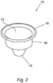
- a candle holder 10 comprises a body 11 having a mouth 12 and a base 14.
- the mouth 12 comprises an opening 13.
- the base 14 comprises an aperture 15.
- Both the opening 13 and the aperture 15 as shown in Figures 1 and 2 are circular in shape. The diameter of the aperture 15 is less than that of the opening 13.
- the opening 13 shown in Figures 1 and 2 is circular in shape, any shape suitable for receipt of a candle may be used, for example, triangular, square, rectangular, oval, octagonal or pentagonal.
- the aperture may be any shape which retains the unburnt candle in the candle holder but allows material from the burnt candle to pass through the aperture.
- the aperture is the same shape as the opening, but this is not essential.
- the opening may be square for receipt of a square candle and the aperture may be circular.
- the mouth 12 and the base 14 are connected by walls 16 comprising three portions 16a, 16b, 16c.
- the walls 16 are substantially vertical, as shown in Figure 1 .
- the walls 16 taper inwardly sharply.
- the walls 16 are tapered gradually inwardly.
- the aperture 15 is defined by the inward most point of the tapered portion of the walls 16c at the base 14.
- the walls 16 are tapered. However, the entire walls may also be tapered such that the tapered portion of the walls extends from the mouth of the candle holder to the base.
- An outwardly extending lip 18 is provided at the mouth 12 of the candle holder 10.
- the lip 18 is sized to abut a mouth of an outer cylinder in which the candle holder 10 is placed.
- the candle holder 10 has a typical top diameter of 6 cm and a typical base diameter of 1.5 cm. Typically, the height of the candle holder 10 is 5.5 cm. However, the size of the candle holder 10 and the degree of tapering of the walls 16 may vary depending upon the size of the candle being used.
- the candle holder 10 may be made from any suitable material, such as glass and/or metal.
- suitable material such as glass and/or metal.
- the use of brass allows efficient transfer of heat throughout the candle holder 10. This results in improved liquefying of candle wax and reduces adherence of candle wax to the candle holder 10. This improves flow of the wax and any other residual material through the aperture 15 of the candle holder 10.
- the candle holder 10 as shown in Figures 1 and 2 comprises a substantially inverted frustoconically shaped holder 10 wherein the mouth 12 is connected to the base 14 by the walls 16.
- the mouth 12 may be connected to the base 14 by spaced apart tapered tines 17, as shown in Figure 3 .
- the inward most point of the tapered tines 17 defines the aperture 15 at the base 14 of the candle holder 10a.
- the candle holder 10a shown in Figure 3 comprises three tines 17 but any suitable number of tines may be used.
- the tines 17 may be made from any suitable material, including, but not limited to, a metal, such as brass.
- the tines 17 are joined to the mouth 12 of the candle holder 10a but are not connected at the base 14. In alternative embodiments, the tines may be held together by any suitable additional or alternative means, such as a rim provided at the base 14 of the candle holder 10a.
- the use of the tines 17 enhances drainage of the wax and other residual material from the candle holder 10a after use as the area of contact between the candle holder 10a and the candle is reduced. This, in turn, reduces the amount of wax adhering to the surface of the candle holder 10a and, thus, remaining in the candle holder 10a after a candle has been burnt.
- the tines 17 may be provided in place of the walls 16. In an alternative embodiment (not shown), the tines 17 may be provided in addition to the walls 16. When used in addition to the walls 16, the tines 17 are positioned between the candle and the walls 16 such that contact there between is prevented. This prevents wax from adhering to the walls 16 of the candle holder 10 during use.
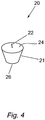
- Figure 4 shows a candle 20 having a frustoconical shape comprising a wick 22 provided at the top 24 thereof.
- the sides 21 of the candle 20 taper inwardly from the top 24 of the candle 20 towards the base 26 such that the diameter of the top 24 of the candle 20 is greater than that of the base 26 of the candle 20.
- both the top 24 and the base 26 are circular in shape but any suitable shape may be used.
- the candle 20 shown in Figure 4 is frustoconical in shape, a candle having an inverted cone shape or other similar shape may also be used.
- the candle 20 is made from a plant wax, such as soya wax.
- soya wax reduces smoke from the candle 20 during burning.
- damage to the interior of the church by smoke is reduced.
- the candle 20 has a typical top diameter of 3 cm and a typical base diameter of 1.5 cm. Typically, the height of the candle 20 is 2.5 cm. The degree of tapering of the walls 21 may vary depending upon the length of the desired burning time of the candle 20.
- the candle 20 is placed in the candle holder 10 as shown in Figure 5 .
- the candle 20 is inserted through the opening 13 of the candle holder 10 and positioned adjacent the third portion 16c.
- the diameter of the base 26 of the candle 20 is approximately equal to the diameter of the aperture 15 of the candle holder 10.
- the tapered walls 16c of the candle holder 10 retain the candle 20 within the candle holder 10.
- the shape and material of the candle holder 10 are designed to improve liquefaction of the wax. This enhances flow of the wax and any other residual material through the aperture 15 of the candle holder 10.
- the walls 16 of the candle holder 10 extend upwardly beyond the top 24 of the candle 20.
- the top 24 of the candle 20 is positioned adjacent the junction between the first portion 16b and the second portion 16c of the candle holder 10. Accordingly, a flame of the candle 20 will be at all times enclosed by the walls 16 of the candle holder 10. This improves safety as an exposed flame may be dangerous, particularly in the case of a church where the building is accessible to the public. This will reduce the high insurance premiums payable by churches and other such buildings where candles are regularly used.
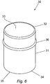
- the candle holder 10 is placed in an outer cylinder 30.
- the outer cylinder 30 comprises a cylindrical body 31 having a mouth 32 and a base 34.
- the mouth 32 comprises a first opening 33 and the base 34 comprises a second opening 35.
- the candle holder 10 is placed in the outer cylinder 30 such that the outwardly extending lip 18 of the candle holder 10 abuts the mouth 32 of the outer cylinder 30, as shown in Figure 7 .
- the outer cylinder 30 is provided with an outwardly extending ledge 36 as shown in Figures 6 and 7 .
- the ledge 36 extends outwardly from the cylindrical body 31. Typically, it is positioned approximately midway between the mouth 32 and the base 34.
- the ledge 36 is sized such that, in use, it abuts the edge of an opening of a candle stand to hold the outer cylinder 30 and candle holder 10 in position.
- the outer cylinder 30 enables the candle holder 10 to be handled without risk of injury.
- the outer cylinder 30 provides additional protection from the flame of the candle 20.
- the outer cylinder 30 has a typical mouth and base diameter of 6 cm. Typically, the height of the outer cylinder 30 is 8 cm. However, the size of the outer cylinder 30 may vary depending upon the size of the candle holder 10.
- FIG 8 shows a candle stand 40 of the type generally found in churches.
- the candle stand 40 comprises a plurality of openings 42 for receipt of the candle holder 10 and outer cylinder 30 of the present invention and supporting means 44.
- the openings 42 are provided in rows wherein the rows are tiered such that the height of the rows increases from a front of the candle stand 40 to the back of the candle stand 40.
- Doors 46 are provided in the back of the candle stand 40 to allow access to a catching means 48 positioned beneath the openings 42.
- the catching means 48 serves to catch residual wax and other waste material produced when a candle is burnt.
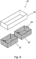
- the catching means 48 shown in Figure 9 comprises a water tray 50 and two netted trays 52.
- the netted trays 52 are provided with handles 54.
- the candle holders 10 are first of all placed in the outer cylinder 30, such that the ledge 36 of each outer cylinder 30 abuts an edge of the opening 42.
- Candles 20 are placed in the candle holders 10. As the candle 20 burns, the wax of the candle 20 is heated and liquefies. The liquefied wax and other waster material, such as the wick, are drawn through the aperture 15 of the candle holder 10. This material falls into the catching means 48 comprising the netted trays 52 positioned within the water tray 50.
- the water tray 50 contains water. At regular intervals, the netted trays 52 are removed from the water tray 50 using the handles 54 and emptied before being replaced in the water tray 50. Several candles may be burnt before emptying of the netted trays 52 is necessary. Wax from the netted trays 52 may be recycled.
- the candle stand 40 has a typical length of 1080 cm, a typical width of 400 cm and a typical height of 1187 cm at the back and 987 cm at the front.
- the catching means comprises a water tray 50 and two netted trays 52.
- any suitable non-flammable and preferably fire retardant liquid may be used in place of water.
- any suitable number of netted trays 52 may be used.
- the catching means may alternatively be provided in the form of a sand pit or otherwise, which is positioned beneath the openings 42 in the candle stand 40.
- the catching means may be removable for cleaning or may be replaced at regular intervals.
- the candle holder and/or outer cylinder may be provided in a range of colours, and in particular in any colour commonly used in religions ceremonies. Suitable colours include red, blue, white and amber. Transparent candle holders and/or transparent other cylinders may also be used. Furthermore, the candle holder and/or outer cylinder may contain designs, drawings, names, etc, for example, the name of the hotel or establishment in which the candle holder or outer cylinder is being used. Typically, the candle holder may be sold in a package comprising four or more candles for use in the home and other environments. The candle holder may be sold, in particular, in retail markets such as shops, supermarkets, pound shops and any other type of retail trade.
Landscapes
- Engineering & Computer Science (AREA)
- General Engineering & Computer Science (AREA)
- Chemical & Material Sciences (AREA)
- Combustion & Propulsion (AREA)
- Mechanical Engineering (AREA)
- Life Sciences & Earth Sciences (AREA)
- General Chemical & Material Sciences (AREA)
- Chemical Kinetics & Catalysis (AREA)
- Oil, Petroleum & Natural Gas (AREA)
- Wood Science & Technology (AREA)
- Organic Chemistry (AREA)
- Arrangement Of Elements, Cooling, Sealing, Or The Like Of Lighting Devices (AREA)
- Fats And Perfumes (AREA)
Claims (12)
- Eine Kerzenhalteranordnung, beinhaltend einen Kerzenhalter (10), eine Kerze (20) und einen Außenzylinder (30),
wobei der Kerzenhalter (10) einen Körper (11) mit einem Mund (12), einer Basis (14) und Seiten (16), die den Mund (12) mit der Basis verbinden (14), beinhaltet,
wobei der Mund (12) eine Aussparung (13) beinhaltet, die angeordnet ist, um eine Kerze (20) aufzunehmen, und wobei mindestens ein Abschnitt der Seiten (16) sich von dem Mund (12) in Richtung der Basis (14) nach innen verjüngt, wobei ein am weitesten innen liegender Punkt des verjüngten Abschnitts (16c) der Seiten (16) eine Öffnung (15) mit einer Größe, die geringer ist als die des breitesten Teils der Kerze (20), definiert, so dass die unverbrannte Kerze (20) vor dem Brennen innerhalb des Kerzenhalters (10) gehalten wird, dadurch gekennzeichnet, dass
die unverbrannte Kerze (20) eine Oberseite (24), eine Basis (26) und Seiten (21) aufweist, welche die Oberseite (24) mit der Basis (26) verbinden, wobei sich mindestens ein Abschnitt der Seiten (21) von der Oberseite (24) zu der Basis (26) der Kerze (20) hin nach innen verjüngt und der verjüngte Abschnitt der Seiten (21) der Kerze (20) dem verjüngten Abschnitt der Seiten (16) des Kerzenhalters (10) entspricht, bevor die Kerze (20) in den Kerzenhalter (10) eingesetzt wird und danach und lediglich durch den verjüngten Abschnitt (16c) der Seiten (16) des Kerzenhalters (10) in dem Kerzenhalter (10) gehalten wird, wobei eine Reduzierung des Außenumfangs der Kerze (20) während des Brennens bewirkt, dass die Kerze (20) durch die Öffnung (15) fällt, wobei der Kerzenhalter (10) eine Lippe (18) beinhaltet, die sich quer von dem Kerzenhalter (10) weg erstreckt,
wobei der Kerzenhalter (10) in dem Außenzylinder (30) bereitgestellt ist, wobei der Außenzylinder (30) einen zylindrischen Körper (31) beinhaltet, der einen Mund (32) und eine Basis (34) aufweist, wobei der Mund (32) eine erste Öffnung (33) beinhaltet und die Basis (34) eine zweite Öffnung (35) beinhaltet, wobei die Lippe (18) auf dem Mund (32) des Außenzylinders (30) sitzt. - Kerzenhalteranordnung gemäß Anspruch 1, wobei der am weitesten innen liegende Punkt des verjüngten Abschnitts (16c) an der Basis (14) des Kerzenhalters (10) bereitgestellt ist.
- Kerzenhalteranordnung gemäß Anspruch 1 oder 2, wobei der am weitesten innen liegende Punkt des verjüngten Abschnitts (16c) der Seiten (16) eine einzige Öffnung (15) definiert.
- Kerzenhalteranordnung gemäß einem der Ansprüche 1 bis 3, wobei die Öffnung (15) frei von Hindernissen ist.
- Kerzenhalteranordnung gemäß einem der Ansprüche 1 bis 4, wobei die Seiten (16) des Kerzenhalters (10) sich nach oben über die Oberseite der Kerze (20) erstrecken, wenn die unverbrannte Kerze (20) im Kerzenhalter (10) positioniert ist.
- Kerzenhalteranordnung gemäß einem der Ansprüche 1 bis 5, wobei die Seiten (16) des Kerzenhalters (10) zwei oder mehr Zinken (17) beinhalten und die unverbrannte Kerze (20) innerhalb des Kerzenhalters (10) durch den sich verjüngenden Abschnitt (16c) der Zinken (17) gehalten wird.
- Kerzenhalteranordnung gemäß einem der Ansprüche 1 bis 5, wobei die Seiten (16) Wände (16) beinhalten und die unverbrannte Kerze (20) innerhalb des Kerzenhalters (10) durch den sich verjüngenden Abschnitt (16c) der Wände (16) gehalten wird.
- Kerzenhalteranordnung gemäß Anspruch 1, wobei der Körper (31) des Außenzylinders (30) eine Leiste (36) beinhaltet, die sich quer von dem Außenzylinder (30) weg erstreckt.
- Kerzenhalteranordnung gemäß einem der vorhergehenden Ansprüche, wobei die Kerze (20) eine Form eines umgekehrten Kegels aufweist, so dass die Basis der Kerze einen Punkt bildet.
- Ein Kerzenständer (40), beinhaltend eine Vielzahl von Aussparungen (42), wobei jede Aussparung (42) eine Kerzenhalteranordnung gemäß einem der Ansprüche 1 bis 8, und ein Fangmittel (48), positioniert unter den Aussparungen (42), für den Fang von durch eine brennende Kerze (20) erzeugtem Abfallmaterial.
- Kerzenständer (40) gemäß Anspruch 10, wobei die Fangeinrichtung (48) beim Gebrauch mit einer nicht brennbaren Flüssigkeit gefüllt ist.
- Kerzenständer (40) gemäß Anspruch 11 oder 10, wobei das Fangmittel (48) mindestens eine netzförmige Schale (52) beinhaltet.
Priority Applications (5)
| Application Number | Priority Date | Filing Date | Title |
|---|---|---|---|
| SI200831565T SI2210038T2 (sl) | 2007-10-10 | 2008-10-09 | Sveče in svečniki |
| HRP20151362TT HRP20151362T4 (hr) | 2007-10-10 | 2008-10-09 | Svijeće i svijećnaci |
| EP15182608.8A EP2963338B1 (de) | 2007-10-10 | 2008-10-09 | Kerzen und kerzenhalter |
| PL08805181T PL2210038T5 (pl) | 2007-10-10 | 2008-10-09 | Świece i świeczniki |
| CY20161100108T CY1117181T1 (el) | 2007-10-10 | 2016-02-10 | Κερια και κηροπηγια |
Applications Claiming Priority (2)
| Application Number | Priority Date | Filing Date | Title |
|---|---|---|---|
| GB0719750A GB2456746A (en) | 2007-10-10 | 2007-10-10 | Candle and Candle Holder |
| PCT/EP2008/063538 WO2009047293A1 (en) | 2007-10-10 | 2008-10-09 | Candles and candle holders |
Related Child Applications (2)
| Application Number | Title | Priority Date | Filing Date |
|---|---|---|---|
| EP15182608.8A Division EP2963338B1 (de) | 2007-10-10 | 2008-10-09 | Kerzen und kerzenhalter |
| EP15182608.8A Division-Into EP2963338B1 (de) | 2007-10-10 | 2008-10-09 | Kerzen und kerzenhalter |
Publications (3)
| Publication Number | Publication Date |
|---|---|
| EP2210038A1 EP2210038A1 (de) | 2010-07-28 |
| EP2210038B1 EP2210038B1 (de) | 2015-11-11 |
| EP2210038B2 true EP2210038B2 (de) | 2019-12-11 |
Family
ID=38787896
Family Applications (2)
| Application Number | Title | Priority Date | Filing Date |
|---|---|---|---|
| EP08805181.8A Active EP2210038B2 (de) | 2007-10-10 | 2008-10-09 | Kerzen und kerzenhalter |
| EP15182608.8A Active EP2963338B1 (de) | 2007-10-10 | 2008-10-09 | Kerzen und kerzenhalter |
Family Applications After (1)
| Application Number | Title | Priority Date | Filing Date |
|---|---|---|---|
| EP15182608.8A Active EP2963338B1 (de) | 2007-10-10 | 2008-10-09 | Kerzen und kerzenhalter |
Country Status (13)
| Country | Link |
|---|---|
| US (1) | US9851095B2 (de) |
| EP (2) | EP2210038B2 (de) |
| AU (1) | AU2008309618A1 (de) |
| CA (1) | CA2701852C (de) |
| CY (1) | CY1117181T1 (de) |
| ES (1) | ES2558932T5 (de) |
| GB (1) | GB2456746A (de) |
| HR (1) | HRP20151362T4 (de) |
| IE (1) | IES20080821A2 (de) |
| PL (1) | PL2210038T5 (de) |
| PT (1) | PT2210038E (de) |
| SI (1) | SI2210038T2 (de) |
| WO (1) | WO2009047293A1 (de) |
Cited By (2)
| Publication number | Priority date | Publication date | Assignee | Title |
|---|---|---|---|---|
| DE202021102874U1 (de) | 2020-06-23 | 2021-06-04 | Astron s. r. o. | Dekorative Lampe |
| DE102022106649B3 (de) | 2022-03-22 | 2023-07-13 | Wolfgang Birmelin | Kerzenhalteranordung |
Families Citing this family (14)
| Publication number | Priority date | Publication date | Assignee | Title |
|---|---|---|---|---|
| GB2456746A (en) | 2007-10-10 | 2009-07-29 | Michael Barrett | Candle and Candle Holder |
| USD646000S1 (en) * | 2010-07-20 | 2011-09-27 | Blackman Larry V | Candle holder adapter |
| USD646001S1 (en) * | 2010-07-20 | 2011-09-27 | Blackman Larry V | Candle holder adapter |
| US9541231B1 (en) * | 2013-06-22 | 2017-01-10 | Celena Misshola Owens | Frame support for creating and displaying handmade paper crafts |
| USD704867S1 (en) * | 2013-07-10 | 2014-05-13 | Heshe and Shulem Management Inc. | Candle |
| USD793587S1 (en) * | 2014-09-23 | 2017-08-01 | Zehavi Pladot Ltd. | Wick and candle holder |
| US20180003376A1 (en) * | 2016-06-29 | 2018-01-04 | Paralee Thiefault | Candle Seal |
| IL258286B (en) * | 2017-05-03 | 2021-06-30 | Kopolovich Haim | Hanukiah |
| AT520525B1 (de) * | 2017-10-16 | 2019-05-15 | Peter Reiter | Anordnung mit einer Kerze und einer Kerzenschale |
| IT201800020602A1 (it) | 2018-12-20 | 2020-06-20 | Cereria Ferrario Srl | Supporto per candela votiva |
| USD916332S1 (en) * | 2019-01-31 | 2021-04-13 | David L. Threlkeld | Candle holder |
| IT201900014361A1 (it) | 2019-08-09 | 2021-02-09 | Vincenzo Bove | Portacandela, candela e candelabro |
| FR3125324B1 (fr) * | 2021-07-19 | 2023-11-10 | Ballon Pub | Dispositif de maintien de bougies |
| USD1101981S1 (en) * | 2022-03-03 | 2025-11-11 | David L. Threlkeld | Candle holder |
Citations (15)
| Publication number | Priority date | Publication date | Assignee | Title |
|---|---|---|---|---|
| GB190924603A (en) † | 1909-10-26 | 1910-10-06 | Louis Dreyfus | Improved Candle Holder. |
| US1704729A (en) † | 1927-05-31 | 1929-03-12 | Danvers O C Deckert | Decorative candle and method of making the same |
| US2025096A (en) † | 1935-05-27 | 1935-12-24 | Danvers O C Deckert | Candle and protecting case therefor |
| GB753059A (en) † | 1953-07-23 | 1956-07-18 | George Murtagh | Candle holders |
| US4158912A (en) † | 1977-11-10 | 1979-06-26 | Hein Werner Erdmann | Candle diameter reducer |
| GB2037895A (en) † | 1977-12-03 | 1980-07-16 | Rolls Royce | Gas Turbine Power Plant |
| GB2045028A (en) † | 1979-03-23 | 1980-10-22 | Thompson M | Improvements to loudspeaking devices |
| US5178451A (en) † | 1990-12-21 | 1993-01-12 | Jh Specialties Inc. | Plastic container for holding water and a candle for use in a luminaria |
| US5292245A (en) † | 1992-08-27 | 1994-03-08 | Spoonhour Kenneth A | Plastic hand held candle holder |
| FR2733821A1 (fr) † | 1995-05-04 | 1996-11-08 | Coutherut Jean | Dispositif anti-feu pour bougies en pot |
| USD442300S1 (en) † | 2000-01-12 | 2001-05-15 | Candle Corporation Of America | Votive candle |
| CA2361199A1 (en) † | 2000-11-09 | 2002-05-09 | Western Oilfields Supply Co. | Container filter box for de-watering solids |
| DE20319435U1 (de) † | 2003-12-14 | 2004-03-11 | Kapitz, Carl-Heinz | Set aus Öllampe und Wachshülle sowie Wachsöllampe |
| USD496473S1 (en) † | 2003-08-13 | 2004-09-21 | D'onofrio Michael | Candle |
| EM04742670003S (de) † | 2006-02-03 | 2006-03-07 | Korona Candles S.A. | Kerzenständer |
Family Cites Families (38)
| Publication number | Priority date | Publication date | Assignee | Title |
|---|---|---|---|---|
| DE7410283U (de) * | 1974-07-04 | Birmelin H | OpferUcht zur Aufstellung auf Opferstöcken in Kirchen, Gedenkstätten oder dergl | |
| US422989A (en) * | 1890-03-11 | Alfred stelzner | ||
| US401592A (en) * | 1889-04-16 | Candlestick | ||
| US679984A (en) | 1900-06-07 | 1901-08-06 | W J Feeley Company Inc | Candelabrum. |
| GB190428634A (en) * | 1904-12-28 | 1905-02-23 | Ernst Paul Lehmann | Improved Candle-holder. |
| US803846A (en) * | 1905-05-11 | 1905-11-07 | Julius Pereira | Process for making candles. |
| GB191024603A (en) * | 1910-10-24 | 1911-09-28 | Betjemann & Sons Ltd G | An Improvement in Dressing or Toilet Tables. |
| GB191110207A (en) * | 1911-04-27 | 1911-12-14 | J H Worrall Son & Co Ltd | Candle Economiser and Grease Guard. |
| US1636994A (en) * | 1926-08-26 | 1927-07-26 | James E Greenan | Votive stand |
| US1926362A (en) | 1931-05-20 | 1933-09-12 | Alois L Berger | Art of candle making |
| US2057943A (en) | 1935-12-14 | 1936-10-20 | George A Friedrichs | Candle holder |
| US2315803A (en) * | 1941-12-10 | 1943-04-06 | Lipari Charles | Safety night light glass |
| US2530288A (en) | 1949-03-17 | 1950-11-14 | Ciano Florence | Candle residue dispenser |
| USRE24423E (en) * | 1954-05-27 | 1958-02-04 | Votive candle | |
| IE21142B1 (en) | 1955-09-30 | 1956-12-31 | Improvements in or relating to candle supports | |
| US3242526A (en) * | 1964-07-15 | 1966-03-29 | Ralph P Wilton | Shaper for candle shanks |
| US3330132A (en) | 1966-01-05 | 1967-07-11 | King Koral Inc | Bobeche |
| SE307409B (de) * | 1966-03-15 | 1969-01-07 | Liljeholmens Stearinfab Ab | |
| FR1579688A (de) * | 1967-07-11 | 1969-08-29 | ||
| DE2628768A1 (de) * | 1976-06-26 | 1977-12-29 | Helmut Zanker | Mehrteiliger kerzenstaender |
| DE2809916C3 (de) * | 1978-03-08 | 1981-03-19 | G. & W. Jaspers, 4441 Hopsten | Kerzenständer mit Heizelement |
| DE7903314U1 (de) * | 1979-02-07 | 1979-05-03 | Birmelin Jun., Hermann, 7800 Freiburg | Halterung fuer ein brenngefaess an tischgestellen fuer opferlichte und/oder an zylindrischen rohren fuer kerzenfoermige leuchtkoerper |
| US4894008A (en) | 1989-04-04 | 1990-01-16 | Sun Lee | Candle holding device |
| TWI239350B (en) * | 1999-12-21 | 2005-09-11 | Johnson & Son Inc S C | Melting plate candles |
| US6171101B1 (en) * | 2000-01-03 | 2001-01-09 | Scott H. Freeman | Decorative candle display |
| DK175239B1 (da) * | 2000-03-01 | 2004-07-19 | Brian Vang Jensen | Lyseholder og fremgangsmåde til fastgörelse af et lys |
| DE10022442B4 (de) | 2000-05-09 | 2004-02-12 | Niermann, Ivo, Dipl.-Ing. | Leuchte |
| US6695611B2 (en) * | 2001-09-19 | 2004-02-24 | Wooil W. Lee | Safety candle |
| SE520737C2 (sv) | 2001-10-10 | 2003-08-19 | Arne Grewin | Ljushållare |
| US20030103346A1 (en) * | 2001-11-30 | 2003-06-05 | Joyner Wendy M. | Method and system for illumination with a plurality of candles |
| DE10207258B4 (de) * | 2002-02-21 | 2005-12-22 | Tischendorf, Dieter, Dr. | Verfahren zur Herstellung von Kerzen, bestehend aus pflanzlichen oder tierischen Ölen oder Fetten |
| DE20219965U1 (de) * | 2002-08-09 | 2003-03-06 | Lauten, Anno, 51069 Köln | Kerzenhalter, Kerzenständer |
| US20040031722A1 (en) * | 2002-08-19 | 2004-02-19 | Marlene Reed | Thematic candle card set |
| US7096623B2 (en) | 2003-12-03 | 2006-08-29 | Cardamone Lisa P | Floral design container system |
| GB2418981A (en) * | 2004-10-09 | 2006-04-12 | Patrick Keogh | A canister used for a wick burning novelty lamp holder |
| FR2891892A1 (fr) * | 2005-10-10 | 2007-04-13 | Casimir Zaniewski | Dispositif pour bruler des bougies avec recuperation des residus |
| DE202006015961U1 (de) * | 2006-10-18 | 2007-02-08 | Sun, Cheng-Seu, Chungho | Wieder füllbarer Kerzenständer |
| GB2456746A (en) * | 2007-10-10 | 2009-07-29 | Michael Barrett | Candle and Candle Holder |
-
2007
- 2007-10-10 GB GB0719750A patent/GB2456746A/en active Pending
-
2008
- 2008-10-09 EP EP08805181.8A patent/EP2210038B2/de active Active
- 2008-10-09 IE IE20080821A patent/IES20080821A2/en not_active IP Right Cessation
- 2008-10-09 PT PT88051818T patent/PT2210038E/pt unknown
- 2008-10-09 CA CA2701852A patent/CA2701852C/en active Active
- 2008-10-09 ES ES08805181T patent/ES2558932T5/es active Active
- 2008-10-09 SI SI200831565T patent/SI2210038T2/sl unknown
- 2008-10-09 PL PL08805181T patent/PL2210038T5/pl unknown
- 2008-10-09 US US12/734,075 patent/US9851095B2/en active Active
- 2008-10-09 EP EP15182608.8A patent/EP2963338B1/de active Active
- 2008-10-09 AU AU2008309618A patent/AU2008309618A1/en not_active Abandoned
- 2008-10-09 WO PCT/EP2008/063538 patent/WO2009047293A1/en not_active Ceased
- 2008-10-09 HR HRP20151362TT patent/HRP20151362T4/hr unknown
-
2016
- 2016-02-10 CY CY20161100108T patent/CY1117181T1/el unknown
Patent Citations (15)
| Publication number | Priority date | Publication date | Assignee | Title |
|---|---|---|---|---|
| GB190924603A (en) † | 1909-10-26 | 1910-10-06 | Louis Dreyfus | Improved Candle Holder. |
| US1704729A (en) † | 1927-05-31 | 1929-03-12 | Danvers O C Deckert | Decorative candle and method of making the same |
| US2025096A (en) † | 1935-05-27 | 1935-12-24 | Danvers O C Deckert | Candle and protecting case therefor |
| GB753059A (en) † | 1953-07-23 | 1956-07-18 | George Murtagh | Candle holders |
| US4158912A (en) † | 1977-11-10 | 1979-06-26 | Hein Werner Erdmann | Candle diameter reducer |
| GB2037895A (en) † | 1977-12-03 | 1980-07-16 | Rolls Royce | Gas Turbine Power Plant |
| GB2045028A (en) † | 1979-03-23 | 1980-10-22 | Thompson M | Improvements to loudspeaking devices |
| US5178451A (en) † | 1990-12-21 | 1993-01-12 | Jh Specialties Inc. | Plastic container for holding water and a candle for use in a luminaria |
| US5292245A (en) † | 1992-08-27 | 1994-03-08 | Spoonhour Kenneth A | Plastic hand held candle holder |
| FR2733821A1 (fr) † | 1995-05-04 | 1996-11-08 | Coutherut Jean | Dispositif anti-feu pour bougies en pot |
| USD442300S1 (en) † | 2000-01-12 | 2001-05-15 | Candle Corporation Of America | Votive candle |
| CA2361199A1 (en) † | 2000-11-09 | 2002-05-09 | Western Oilfields Supply Co. | Container filter box for de-watering solids |
| USD496473S1 (en) † | 2003-08-13 | 2004-09-21 | D'onofrio Michael | Candle |
| DE20319435U1 (de) † | 2003-12-14 | 2004-03-11 | Kapitz, Carl-Heinz | Set aus Öllampe und Wachshülle sowie Wachsöllampe |
| EM04742670003S (de) † | 2006-02-03 | 2006-03-07 | Korona Candles S.A. | Kerzenständer |
Non-Patent Citations (1)
| Title |
|---|
| RCD000809660-0001 † |
Cited By (2)
| Publication number | Priority date | Publication date | Assignee | Title |
|---|---|---|---|---|
| DE202021102874U1 (de) | 2020-06-23 | 2021-06-04 | Astron s. r. o. | Dekorative Lampe |
| DE102022106649B3 (de) | 2022-03-22 | 2023-07-13 | Wolfgang Birmelin | Kerzenhalteranordung |
Also Published As
| Publication number | Publication date |
|---|---|
| PT2210038E (pt) | 2016-01-26 |
| ES2558932T3 (es) | 2016-02-09 |
| HRP20151362T4 (hr) | 2020-02-21 |
| EP2210038A1 (de) | 2010-07-28 |
| SI2210038T1 (sl) | 2016-02-29 |
| CA2701852C (en) | 2015-11-24 |
| AU2008309618A1 (en) | 2009-04-16 |
| ES2558932T5 (es) | 2020-06-22 |
| PL2210038T3 (pl) | 2016-05-31 |
| CY1117181T1 (el) | 2017-04-05 |
| US20100291500A1 (en) | 2010-11-18 |
| PL2210038T5 (pl) | 2020-06-29 |
| EP2963338B1 (de) | 2020-07-22 |
| US9851095B2 (en) | 2017-12-26 |
| WO2009047293A1 (en) | 2009-04-16 |
| EP2963338A1 (de) | 2016-01-06 |
| IES20080821A2 (en) | 2009-04-29 |
| CA2701852A1 (en) | 2009-04-16 |
| EP2210038B1 (de) | 2015-11-11 |
| SI2210038T2 (sl) | 2020-02-28 |
| HRP20151362T1 (hr) | 2016-02-26 |
| GB2456746A (en) | 2009-07-29 |
| GB0719750D0 (en) | 2007-11-21 |
Similar Documents
| Publication | Publication Date | Title |
|---|---|---|
| EP2210038B1 (de) | Kerzen und kerzenhalter | |
| JP4944893B2 (ja) | 取外し可能なトレーカバーを備えた食品保存キャビネット | |
| US9341365B2 (en) | Eversible candle holder | |
| US20040032733A1 (en) | Candle carrier for use with candle accessories burning tea light candles | |
| US20190168272A1 (en) | Wax Warmer Liner | |
| JP2003304967A (ja) | 灯明台 | |
| US20080011236A1 (en) | Bug trap pet bowl | |
| US4262325A (en) | Altar with candle holder | |
| US20090233251A1 (en) | Candle, a candle holder, a candle holding socket, a candelabrum and a method of making a candle | |
| US12523371B2 (en) | Reusable candle system | |
| US20120067769A1 (en) | Modular storage container | |
| US6562302B1 (en) | Incense tray with blower and plurality of incense holders | |
| US20210214125A1 (en) | Reusable Wax Warmer Liner | |
| US4181927A (en) | Candle holder | |
| US20030209554A1 (en) | Fragrance-carrier composition retainer | |
| US20090068607A1 (en) | Outdoor candles | |
| US20090092938A1 (en) | Candle maker and redresser | |
| KR20090002569U (ko) | 모기향 연소기 | |
| DE102022106649B3 (de) | Kerzenhalteranordung | |
| AU2016101899A4 (en) | Candle / oil diffuser | |
| KR20090005914U (ko) | 절취선이 형성된 케익 받침대 | |
| AU721801B2 (en) | Essential oil evaporator | |
| AU709044B3 (en) | Ashtray | |
| EP3263984A1 (de) | Kerzendichtung | |
| KR200315614Y1 (ko) | 돌판구이기 |
Legal Events
| Date | Code | Title | Description |
|---|---|---|---|
| PUAI | Public reference made under article 153(3) epc to a published international application that has entered the european phase |
Free format text: ORIGINAL CODE: 0009012 |
|
| 17P | Request for examination filed |
Effective date: 20100423 |
|
| AK | Designated contracting states |
Kind code of ref document: A1 Designated state(s): AT BE BG CH CY CZ DE DK EE ES FI FR GB GR HR HU IE IS IT LI LT LU LV MC MT NL NO PL PT RO SE SI SK TR |
|
| AX | Request for extension of the european patent |
Extension state: AL BA MK RS |
|
| 17Q | First examination report despatched |
Effective date: 20130321 |
|
| TPAC | Observations filed by third parties |
Free format text: ORIGINAL CODE: EPIDOSNTIPA |
|
| TPAC | Observations filed by third parties |
Free format text: ORIGINAL CODE: EPIDOSNTIPA |
|
| TPAC | Observations filed by third parties |
Free format text: ORIGINAL CODE: EPIDOSNTIPA |
|
| GRAP | Despatch of communication of intention to grant a patent |
Free format text: ORIGINAL CODE: EPIDOSNIGR1 |
|
| RAP1 | Party data changed (applicant data changed or rights of an application transferred) |
Owner name: MURPHY, MICHAEL Owner name: BARRETT, MICHAEL |
|
| RIN1 | Information on inventor provided before grant (corrected) |
Inventor name: BARRETT, MICHAEL Inventor name: MURPHY, MICHAEL |
|
| GRAS | Grant fee paid |
Free format text: ORIGINAL CODE: EPIDOSNIGR3 |
|
| INTG | Intention to grant announced |
Effective date: 20150616 |
|
| TPAC | Observations filed by third parties |
Free format text: ORIGINAL CODE: EPIDOSNTIPA |
|
| GRAA | (expected) grant |
Free format text: ORIGINAL CODE: 0009210 |
|
| AK | Designated contracting states |
Kind code of ref document: B1 Designated state(s): AT BE BG CH CY CZ DE DK EE ES FI FR GB GR HR HU IE IS IT LI LT LU LV MC MT NL NO PL PT RO SE SI SK TR |
|
| AX | Request for extension of the european patent |
Extension state: AL BA MK RS |
|
| REG | Reference to a national code |
Ref country code: GB Ref legal event code: FG4D |
|
| REG | Reference to a national code |
Ref country code: CH Ref legal event code: EP |
|
| REG | Reference to a national code |
Ref country code: IE Ref legal event code: FG4D |
|
| REG | Reference to a national code |
Ref country code: HR Ref legal event code: TUEP Ref document number: P20151362 Country of ref document: HR |
|
| REG | Reference to a national code |
Ref country code: AT Ref legal event code: REF Ref document number: 760650 Country of ref document: AT Kind code of ref document: T Effective date: 20151215 |
|
| REG | Reference to a national code |
Ref country code: DE Ref legal event code: R096 Ref document number: 602008041167 Country of ref document: DE |
|
| REG | Reference to a national code |
Ref country code: PT Ref legal event code: SC4A Free format text: AVAILABILITY OF NATIONAL TRANSLATION Effective date: 20151221 |
|
| REG | Reference to a national code |
Ref country code: CH Ref legal event code: NV Representative=s name: MURGITROYD AND COMPANY, CH |
|
| REG | Reference to a national code |
Ref country code: ES Ref legal event code: FG2A Ref document number: 2558932 Country of ref document: ES Kind code of ref document: T3 Effective date: 20160209 |
|
| REG | Reference to a national code |
Ref country code: HR Ref legal event code: T1PR Ref document number: P20151362 Country of ref document: HR |
|
| REG | Reference to a national code |
Ref country code: NL Ref legal event code: FP |
|
| PG25 | Lapsed in a contracting state [announced via postgrant information from national office to epo] |
Ref country code: NO Free format text: LAPSE BECAUSE OF FAILURE TO SUBMIT A TRANSLATION OF THE DESCRIPTION OR TO PAY THE FEE WITHIN THE PRESCRIBED TIME-LIMIT Effective date: 20160211 Ref country code: IS Free format text: LAPSE BECAUSE OF FAILURE TO SUBMIT A TRANSLATION OF THE DESCRIPTION OR TO PAY THE FEE WITHIN THE PRESCRIBED TIME-LIMIT Effective date: 20160311 |
|
| PG25 | Lapsed in a contracting state [announced via postgrant information from national office to epo] |
Ref country code: SE Free format text: LAPSE BECAUSE OF FAILURE TO SUBMIT A TRANSLATION OF THE DESCRIPTION OR TO PAY THE FEE WITHIN THE PRESCRIBED TIME-LIMIT Effective date: 20151111 Ref country code: FI Free format text: LAPSE BECAUSE OF FAILURE TO SUBMIT A TRANSLATION OF THE DESCRIPTION OR TO PAY THE FEE WITHIN THE PRESCRIBED TIME-LIMIT Effective date: 20151111 Ref country code: LV Free format text: LAPSE BECAUSE OF FAILURE TO SUBMIT A TRANSLATION OF THE DESCRIPTION OR TO PAY THE FEE WITHIN THE PRESCRIBED TIME-LIMIT Effective date: 20151111 Ref country code: GR Free format text: LAPSE BECAUSE OF FAILURE TO SUBMIT A TRANSLATION OF THE DESCRIPTION OR TO PAY THE FEE WITHIN THE PRESCRIBED TIME-LIMIT Effective date: 20160212 |
|
| REG | Reference to a national code |
Ref country code: SK Ref legal event code: T3 Ref document number: E 20216 Country of ref document: SK |
|
| REG | Reference to a national code |
Ref country code: DE Ref legal event code: R026 Ref document number: 602008041167 Country of ref document: DE |
|
| PLBI | Opposition filed |
Free format text: ORIGINAL CODE: 0009260 |
|
| PLBI | Opposition filed |
Free format text: ORIGINAL CODE: 0009260 |
|
| PG25 | Lapsed in a contracting state [announced via postgrant information from national office to epo] |
Ref country code: RO Free format text: LAPSE BECAUSE OF FAILURE TO SUBMIT A TRANSLATION OF THE DESCRIPTION OR TO PAY THE FEE WITHIN THE PRESCRIBED TIME-LIMIT Effective date: 20151111 Ref country code: DK Free format text: LAPSE BECAUSE OF FAILURE TO SUBMIT A TRANSLATION OF THE DESCRIPTION OR TO PAY THE FEE WITHIN THE PRESCRIBED TIME-LIMIT Effective date: 20151111 Ref country code: EE Free format text: LAPSE BECAUSE OF FAILURE TO SUBMIT A TRANSLATION OF THE DESCRIPTION OR TO PAY THE FEE WITHIN THE PRESCRIBED TIME-LIMIT Effective date: 20151111 |
|
| 26 | Opposition filed |
Opponent name: GRAZIANI S.R.L. Effective date: 20160802 |
|
| PLAX | Notice of opposition and request to file observation + time limit sent |
Free format text: ORIGINAL CODE: EPIDOSNOBS2 |
|
| 26 | Opposition filed |
Opponent name: DUFFY & SCOTT CANDLEMAKERS LIMITED Effective date: 20160810 |
|
| REG | Reference to a national code |
Ref country code: FR Ref legal event code: PLFP Year of fee payment: 9 |
|
| PLBB | Reply of patent proprietor to notice(s) of opposition received |
Free format text: ORIGINAL CODE: EPIDOSNOBS3 |
|
| REG | Reference to a national code |
Ref country code: FR Ref legal event code: PLFP Year of fee payment: 10 |
|
| REG | Reference to a national code |
Ref country code: FR Ref legal event code: PLFP Year of fee payment: 10 |
|
| APAH | Appeal reference modified |
Free format text: ORIGINAL CODE: EPIDOSCREFNO |
|
| APBM | Appeal reference recorded |
Free format text: ORIGINAL CODE: EPIDOSNREFNO |
|
| APBP | Date of receipt of notice of appeal recorded |
Free format text: ORIGINAL CODE: EPIDOSNNOA2O |
|
| APBM | Appeal reference recorded |
Free format text: ORIGINAL CODE: EPIDOSNREFNO |
|
| APBP | Date of receipt of notice of appeal recorded |
Free format text: ORIGINAL CODE: EPIDOSNNOA2O |
|
| APBM | Appeal reference recorded |
Free format text: ORIGINAL CODE: EPIDOSNREFNO |
|
| APBP | Date of receipt of notice of appeal recorded |
Free format text: ORIGINAL CODE: EPIDOSNNOA2O |
|
| APAH | Appeal reference modified |
Free format text: ORIGINAL CODE: EPIDOSCREFNO |
|
| APBQ | Date of receipt of statement of grounds of appeal recorded |
Free format text: ORIGINAL CODE: EPIDOSNNOA3O |
|
| PG25 | Lapsed in a contracting state [announced via postgrant information from national office to epo] |
Ref country code: HU Free format text: LAPSE BECAUSE OF FAILURE TO SUBMIT A TRANSLATION OF THE DESCRIPTION OR TO PAY THE FEE WITHIN THE PRESCRIBED TIME-LIMIT; INVALID AB INITIO Effective date: 20081009 |
|
| APBQ | Date of receipt of statement of grounds of appeal recorded |
Free format text: ORIGINAL CODE: EPIDOSNNOA3O |
|
| PG25 | Lapsed in a contracting state [announced via postgrant information from national office to epo] |
Ref country code: TR Free format text: LAPSE BECAUSE OF FAILURE TO SUBMIT A TRANSLATION OF THE DESCRIPTION OR TO PAY THE FEE WITHIN THE PRESCRIBED TIME-LIMIT Effective date: 20151111 |
|
| PG25 | Lapsed in a contracting state [announced via postgrant information from national office to epo] |
Ref country code: BG Free format text: LAPSE BECAUSE OF FAILURE TO SUBMIT A TRANSLATION OF THE DESCRIPTION OR TO PAY THE FEE WITHIN THE PRESCRIBED TIME-LIMIT Effective date: 20151111 |
|
| REG | Reference to a national code |
Ref country code: FR Ref legal event code: PLFP Year of fee payment: 11 |
|
| REG | Reference to a national code |
Ref country code: AT Ref legal event code: UEP Ref document number: 760650 Country of ref document: AT Kind code of ref document: T Effective date: 20151111 |
|
| APBU | Appeal procedure closed |
Free format text: ORIGINAL CODE: EPIDOSNNOA9O |
|
| REG | Reference to a national code |
Ref country code: HR Ref legal event code: ODRP Ref document number: P20151362 Country of ref document: HR Payment date: 20190926 Year of fee payment: 12 |
|
| PG25 | Lapsed in a contracting state [announced via postgrant information from national office to epo] |
Ref country code: IT Free format text: LAPSE BECAUSE OF NON-PAYMENT OF DUE FEES Effective date: 20181009 |
|
| PUAH | Patent maintained in amended form |
Free format text: ORIGINAL CODE: 0009272 |
|
| STAA | Information on the status of an ep patent application or granted ep patent |
Free format text: STATUS: PATENT MAINTAINED AS AMENDED |
|
| REG | Reference to a national code |
Ref country code: CH Ref legal event code: AELC |
|
| 27A | Patent maintained in amended form |
Effective date: 20191211 |
|
| AK | Designated contracting states |
Kind code of ref document: B2 Designated state(s): AT BE BG CH CY CZ DE DK EE ES FI FR GB GR HR HU IE IS IT LI LT LU LV MC MT NL NO PL PT RO SE SI SK TR |
|
| AX | Request for extension of the european patent |
Extension state: AL BA MK RS |
|
| REG | Reference to a national code |
Ref country code: DE Ref legal event code: R102 Ref document number: 602008041167 Country of ref document: DE |
|
| REG | Reference to a national code |
Ref country code: HR Ref legal event code: T4IZ Ref document number: P20151362 Country of ref document: HR |
|
| PG25 | Lapsed in a contracting state [announced via postgrant information from national office to epo] |
Ref country code: IT Free format text: LAPSE BECAUSE OF NON-PAYMENT OF DUE FEES Effective date: 20181009 |
|
| PGRI | Patent reinstated in contracting state [announced from national office to epo] |
Ref country code: IT Effective date: 20191111 |
|
| REG | Reference to a national code |
Ref country code: NL Ref legal event code: FP |
|
| REG | Reference to a national code |
Ref country code: SK Ref legal event code: T5 Ref document number: E 20216 Country of ref document: SK |
|
| REG | Reference to a national code |
Ref country code: ES Ref legal event code: DC2A Ref document number: 2558932 Country of ref document: ES Kind code of ref document: T5 Effective date: 20200622 |
|
| REG | Reference to a national code |
Ref country code: HR Ref legal event code: ODRP Ref document number: P20151362 Country of ref document: HR Payment date: 20200924 Year of fee payment: 13 |
|
| REG | Reference to a national code |
Ref country code: HR Ref legal event code: ODRP Ref document number: P20151362 Country of ref document: HR Payment date: 20211001 Year of fee payment: 14 |
|
| REG | Reference to a national code |
Ref country code: HR Ref legal event code: ODRP Ref document number: P20151362 Country of ref document: HR Payment date: 20220929 Year of fee payment: 15 |
|
| P01 | Opt-out of the competence of the unified patent court (upc) registered |
Effective date: 20230802 |
|
| REG | Reference to a national code |
Ref country code: HR Ref legal event code: ODRP Ref document number: P20151362 Country of ref document: HR Payment date: 20230926 Year of fee payment: 16 |
|
| PGFP | Annual fee paid to national office [announced via postgrant information from national office to epo] |
Ref country code: MT Payment date: 20231004 Year of fee payment: 16 |
|
| REG | Reference to a national code |
Ref country code: HR Ref legal event code: ODRP Ref document number: P20151362 Country of ref document: HR Payment date: 20240927 Year of fee payment: 17 |
|
| REG | Reference to a national code |
Ref country code: AT Ref legal event code: UEP Ref document number: 760650 Country of ref document: AT Kind code of ref document: T Effective date: 20191211 |
|
| PGFP | Annual fee paid to national office [announced via postgrant information from national office to epo] |
Ref country code: PT Payment date: 20250929 Year of fee payment: 18 |
|
| PGFP | Annual fee paid to national office [announced via postgrant information from national office to epo] |
Ref country code: PL Payment date: 20250929 Year of fee payment: 18 |
|
| REG | Reference to a national code |
Ref country code: HR Ref legal event code: ODRP Ref document number: P20151362 Country of ref document: HR Payment date: 20250930 Year of fee payment: 18 |
|
| PGFP | Annual fee paid to national office [announced via postgrant information from national office to epo] |
Ref country code: LV Payment date: 20250930 Year of fee payment: 18 |
|
| PGFP | Annual fee paid to national office [announced via postgrant information from national office to epo] |
Ref country code: SI Payment date: 20251008 Year of fee payment: 18 |
|
| REG | Reference to a national code |
Ref country code: CH Ref legal event code: U11 Free format text: ST27 STATUS EVENT CODE: U-0-0-U10-U11 (AS PROVIDED BY THE NATIONAL OFFICE) Effective date: 20251101 |
|
| PGFP | Annual fee paid to national office [announced via postgrant information from national office to epo] |
Ref country code: LU Payment date: 20251030 Year of fee payment: 18 Ref country code: NL Payment date: 20251030 Year of fee payment: 18 |
|
| PGFP | Annual fee paid to national office [announced via postgrant information from national office to epo] |
Ref country code: DE Payment date: 20251031 Year of fee payment: 18 |
|
| PGFP | Annual fee paid to national office [announced via postgrant information from national office to epo] |
Ref country code: LT Payment date: 20251001 Year of fee payment: 18 Ref country code: GB Payment date: 20251031 Year of fee payment: 18 |
|
| PGFP | Annual fee paid to national office [announced via postgrant information from national office to epo] |
Ref country code: MC Payment date: 20251030 Year of fee payment: 18 |
|
| PGFP | Annual fee paid to national office [announced via postgrant information from national office to epo] |
Ref country code: AT Payment date: 20251103 Year of fee payment: 18 |
|
| PGFP | Annual fee paid to national office [announced via postgrant information from national office to epo] |
Ref country code: IT Payment date: 20251029 Year of fee payment: 18 |
|
| PGFP | Annual fee paid to national office [announced via postgrant information from national office to epo] |
Ref country code: FR Payment date: 20251028 Year of fee payment: 18 Ref country code: HR Payment date: 20251009 Year of fee payment: 18 |
|
| PGFP | Annual fee paid to national office [announced via postgrant information from national office to epo] |
Ref country code: BE Payment date: 20251030 Year of fee payment: 18 |
|
| PGFP | Annual fee paid to national office [announced via postgrant information from national office to epo] |
Ref country code: CH Payment date: 20251101 Year of fee payment: 18 |
|
| PGFP | Annual fee paid to national office [announced via postgrant information from national office to epo] |
Ref country code: CY Payment date: 20251003 Year of fee payment: 18 Ref country code: CZ Payment date: 20251007 Year of fee payment: 18 Ref country code: IE Payment date: 20251030 Year of fee payment: 18 |
|
| PGFP | Annual fee paid to national office [announced via postgrant information from national office to epo] |
Ref country code: SK Payment date: 20251007 Year of fee payment: 18 |
|
| PGFP | Annual fee paid to national office [announced via postgrant information from national office to epo] |
Ref country code: ES Payment date: 20251106 Year of fee payment: 18 |