EP2209581B1 - Schaltmodul für das leistungsteil einer schweisssteuerung - Google Patents
Schaltmodul für das leistungsteil einer schweisssteuerung Download PDFInfo
- Publication number
- EP2209581B1 EP2209581B1 EP20080785667 EP08785667A EP2209581B1 EP 2209581 B1 EP2209581 B1 EP 2209581B1 EP 20080785667 EP20080785667 EP 20080785667 EP 08785667 A EP08785667 A EP 08785667A EP 2209581 B1 EP2209581 B1 EP 2209581B1
- Authority
- EP
- European Patent Office
- Prior art keywords
- current supply
- switching
- cooling
- supply means
- insulation
- Prior art date
- Legal status (The legal status is an assumption and is not a legal conclusion. Google has not performed a legal analysis and makes no representation as to the accuracy of the status listed.)
- Active
Links
- 238000003466 welding Methods 0.000 title claims description 34
- 238000001816 cooling Methods 0.000 claims description 29
- 238000009413 insulation Methods 0.000 claims description 15
- XAGFODPZIPBFFR-UHFFFAOYSA-N aluminium Chemical compound [Al] XAGFODPZIPBFFR-UHFFFAOYSA-N 0.000 claims description 6
- 229910052782 aluminium Inorganic materials 0.000 claims description 6
- 239000000110 cooling liquid Substances 0.000 claims description 6
- 239000012530 fluid Substances 0.000 claims description 6
- 238000004519 manufacturing process Methods 0.000 claims description 6
- 239000004065 semiconductor Substances 0.000 claims description 2
- 229920001059 synthetic polymer Polymers 0.000 claims description 2
- 229920001169 thermoplastic Polymers 0.000 claims description 2
- 239000004416 thermosoftening plastic Substances 0.000 claims description 2
- 239000004020 conductor Substances 0.000 claims 2
- 239000004411 aluminium Substances 0.000 claims 1
- 239000012809 cooling fluid Substances 0.000 claims 1
- 230000002787 reinforcement Effects 0.000 claims 1
- 239000002826 coolant Substances 0.000 description 16
- RYGMFSIKBFXOCR-UHFFFAOYSA-N Copper Chemical compound [Cu] RYGMFSIKBFXOCR-UHFFFAOYSA-N 0.000 description 3
- 229910052802 copper Inorganic materials 0.000 description 3
- 239000010949 copper Substances 0.000 description 3
- 229920006268 silicone film Polymers 0.000 description 3
- 239000003365 glass fiber Substances 0.000 description 2
- 238000012856 packing Methods 0.000 description 2
- 239000003795 chemical substances by application Substances 0.000 description 1
- 238000010276 construction Methods 0.000 description 1
- 230000001419 dependent effect Effects 0.000 description 1
- 238000010586 diagram Methods 0.000 description 1
- 238000010292 electrical insulation Methods 0.000 description 1
- 238000001125 extrusion Methods 0.000 description 1
- 239000004744 fabric Substances 0.000 description 1
- 239000011888 foil Substances 0.000 description 1
- 230000017525 heat dissipation Effects 0.000 description 1
- 230000010354 integration Effects 0.000 description 1
- 238000002955 isolation Methods 0.000 description 1
- 239000000463 material Substances 0.000 description 1
- 238000000034 method Methods 0.000 description 1
- 229920003223 poly(pyromellitimide-1,4-diphenyl ether) Polymers 0.000 description 1
- 238000005086 pumping Methods 0.000 description 1
- 239000012744 reinforcing agent Substances 0.000 description 1
Images

Classifications
-
- B—PERFORMING OPERATIONS; TRANSPORTING
- B23—MACHINE TOOLS; METAL-WORKING NOT OTHERWISE PROVIDED FOR
- B23K—SOLDERING OR UNSOLDERING; WELDING; CLADDING OR PLATING BY SOLDERING OR WELDING; CUTTING BY APPLYING HEAT LOCALLY, e.g. FLAME CUTTING; WORKING BY LASER BEAM
- B23K9/00—Arc welding or cutting
- B23K9/32—Accessories
- B23K9/323—Combined coupling means, e.g. gas, electricity, water or the like
Definitions
- the invention relates to a switching module for the power part of a welding control, according to the independent claim 1 and a manufacturing method for such a module according to claim 10.
- the components are heat-screwed onto strand hollow sections, which are penetrated by a fluid, for example by means of a guided in a cooling circuit cooling liquid.
- a material for the extruded hollow sections for example, aluminum is suitable because of its properties, in particular its very good thermal conductivity and processability in the extrusion process.
- the publication DE 102 45 288 A1 shows the power unit for a power converter and a method for producing the same.
- the FIG. 1 This publication shows a schematic representation of a section through the inverter power unit.
- an IGBT module is mounted on a heat sink and disk cell diodes are mounted on the same heat sink.
- the collector of the illustrated IGBT is connected to the cathode of the disk cell diodes via a large-area low-inductive copper rail.
- the emitter of the IGBT is over another large area Low-inductance copper bar connected to the anode of the disc cell diode.
- the two copper bars are separated by an insulating layer and electrically insulated from each other. How to get in FIG.
- FIG. 1 clearly sees the said publication, the current-carrying rail is arranged directly on the heat sink.
- FIG. 1 only shows a one-sided cooling of the disc cell diode. It is also noted in the published patent application that an additional heat sink can be arranged from the top in order to improve the utilization of the diode. Accordingly, then the power supply rails would be arranged between two heat sinks.
- Similar devices are also known in connection with the power section of AC welding controls.
- the heatsink are used simultaneously to the power line and thus also the potential of the power supply to these heat sinks.
- the heat sinks are connected by means of cooling hoses, so that it is possible to exchange cooling liquid between the heat sinks.
- the cooling liquid must flow by means of a first coolant supply into a first heat sink and continue to flow by means of the connection from the first to the second heat sink. At an outlet opening of the second heat sink, the cooling liquid exits again.
- the disadvantage of this arrangement is that due to the prevailing potential difference between the heat sinks and between the heat sinks and the hose connections on the housing, the hoses must inherently have a certain length, so that the dielectric strength between the potentials at the power unit and the ground potential is always present. This depends on the dielectric strength to be dimensioned hose length must be accommodated within the Kompakt horrgephinuses spatially and requires corresponding space requirements. In addition, expensive special hoses are required. The known from the prior art arrangement therefore leads to a less compact and expensive to manufacture solution because of the assembly costs for the hoses and the high price of the special hoses is obtained.
- the object of the invention is to find a solution which avoids these disadvantages as far as possible.
- a second switching means, a second coolant and a second power supply means are provided, wherein a first terminal of the switching means on the first power supply means and a second terminal of the switching means on the second Stromzu meltschul is applied, wherein the switching means are arranged in anti-parallel connection between two Stromzu meltschuln and wherein the switching means and Power supply means are arranged between the first and the second coolant and wherein a second insulation means is also arranged between the second power supply means and the second coolant.
- the switching module according to the invention can be accommodated easily and compactly in the housing of a welding control.
- the insulating means is realized by means of an electrically insulating and thermally conductive foil or a plate.
- it is thermoplastic or made of synthetic polymers insulation means.
- films or plates can be purchased inexpensively and easily be placed between the power supply and coolant in the production of the switching modules without much effort, so that they isolate both means over the entire area.
- the insulating means is additionally reinforced by means of a reinforcing agent, for example a glass fiber fabric, which has been incorporated into the film or plate. This prevents any pressure or shear forces that might occur during assembly of the switch module from damaging the film.
- a reinforcing agent for example a glass fiber fabric
- the switching means, the cooling means, the power supply means and the isolation means are clamped between two clamping means.
- the clamping means can be realized for example by means of two tension springs, wherein the tension springs rest on both sides of the coolant and are pressed by means of a threaded rod and screwed on both sides of the threaded rod nuts to the coolant.
- the switching module comprises a connecting means which can be arranged between the two cooling means and allows the exchange of a cooling liquid between the two cooling means.
- the fluid can be supplied to the first coolant by means of an inlet, and the fluid can flow from the first to the second coolant by means of the connection means and by means of an outlet on the second coolant, the fluid can flow out of the second coolant again.
- a coolant circulation can be realized, which ensures a maximum heat dissipation directly to the heat source.
- the coolant is a hollow profile, for example made of aluminum.
- the switching means installed in the switching module are preferably power semiconductors, in particular thyristor cells in the form of disk cells, which can be obtained inexpensively as a mass product.
- this control can be implemented very compactly and inexpensively because fewer supply lines are required for the cooling of the switching module due to the inventive mounting of the insulation.
- the switching module according to the invention for power parts of a welding device is generally moved so that first the Stromzu Swiss Kunststoff, so for example, current-carrying rails, to the switching means, such as thyristor cells are arranged. Subsequently, the insulating means, for example, an insulating film, applied to the current-carrying rails, and then the heat sink are placed on the insulating means over the entire surface and fixed by means of the already mentioned tension springs.
- the insulating means for example, an insulating film
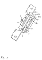
- FIG. 1 a perspective view of the switching module according to the invention and FIG. 2 schematically the circuitry integration of the switching module according to the invention in an AC resistance welding system, wherein the welding control is not shown here.
- FIG. 1 shows a perspective view of the switching module with two thyristor cells 2A and 2B, two cooling means 3A and 3B made of aluminum, two power supply means or current-carrying rails 1A and 1B, two insulation means 8A, 8B in the form of insulating armored films (glass fiber reinforced silicone film or films with the brand name Kapton), as well as a tension spring 4 (second tension spring not shown) and a threaded rod 9 with nut 10 (second nut not shown).
- the thyristor cells 2A, 2B are arranged centrally and mounted between the current-carrying rails 1A, 1B in such a way that they rest against the rails 1A, 1B over their entire area by means of their connections.
- the glass-fiber-reinforced silicone film 8A, 8B is arranged on both sides in such a way that the cooling body 3A or 3B rests completely on this film and is electrically insulated from the current-carrying rail 1A or 1B.
- a hose can be connected, which feeds a guided by a pump coolant into the heat sink 3A.
- the coolant from the heat sink 3 A flow to the heat sink 3 B and are guided back into the pump circuit by means of the outlet 7 of the second heat sink.
- FIG. 2 shows the schematic diagram of an AC resistance welding device fragmentary, in particular here the welding transformer 11, which is the primary side controllable by means of the switching module 12 according to the invention, so that the secondary side arranged welding assembly 11, for example, the welding gun of a resistance welding system, can be acted upon with welding current. Additionally shown are two current measuring points 14, which can detect the change of the welding current on the primary side and the secondary side and forward it to a welding controller 14.
- the thyristors 2A, 2B of the switching device according to the invention are ignited for welding current control in the mode "current control” at a fixed predetermined phase angle value.
- the current that has occurred in the past is also used by the welding control to calculate the new phase-angle value.
Landscapes
- Engineering & Computer Science (AREA)
- Physics & Mathematics (AREA)
- Plasma & Fusion (AREA)
- Mechanical Engineering (AREA)
- Cooling Or The Like Of Semiconductors Or Solid State Devices (AREA)
- Rectifiers (AREA)
- Lining Or Joining Of Plastics Or The Like (AREA)
- Cooling Or The Like Of Electrical Apparatus (AREA)
Description
- Die Erfindung betrifft ein Schaltmodul für das Leistungsteil einer Schweißsteuerung, gemäß dem unabhängigen Anspruch 1 sowie ein Herstellverfahren für ein solches Modul nach Anspruch 10.
- Im Zuge der Entwicklung neuer Schweißsteuerungen werden immer höhere Packungsdichten der leistungselektronischen Komponenten gefordert, um die Baugröße des Gerätes möglichst klein zu halten. Diese immer höheren Packungsdichten erfordern eine aktive Verlustleistungsabführung. Üblicherweise werden hierzu die Komponenten wärmeschlüssig auf Stranghohlprofile aufgeschraubt, die von einem Fluid, beispielsweise mittels einer in einem Kühlkreislauf geführten Kühlflüssigkeit, durchsetzt werden. Als Material für die Stranghohlprofile eignet sich beispielsweise Aluminium aufgrund seiner Eigenschaften, insbesondere seiner sehr guten Wärmeleitfähigkeit und Verarbeitbarkeit im Strangpressverfahren.
- Die Offenlegungsschrift
DE 102 45 288 A1 zeigt das Leistungsteil für einen Stromumrichter und ein Verfahren zur Herstellung desselben. DieFigur 1 dieser Offenlegungsschrift zeigt eine schematische Darstellung eines Schnitts durch das Umrichterleistungsteil. Dabei ist ein IGBT-Modul auf einem Kühlkörper montiert und auf demselben Kühlkörper sind auch Scheibenzellendioden angebracht. Der Kollektor des dargestellten IGBTs ist über eine großflächige niederinduktive Kupferschiene mit der Kathode der Scheibenzellendioden verbunden. Der Emitter des IGBTs ist über eine weitere großflächige niederinduktive Kupferschiene mit der Anode der Scheibenzellendiode verbunden. Im Bereich des IGBT-Moduls sind die beiden Kupferschienen mittels einer Isolationsschicht getrennt und elektrisch voneinander isoliert. Wie man inFigur 1 der genannten Offenlegungsschrift deutlich sieht, ist die stromführende Schiene unmittelbar auf dem Kühlkörper angeordnet.Figur 1 zeigt lediglich eine einseitige Kühlung der Scheibenzellendiode. Es wird in der Offenlegungsschrift auch darauf hingewiesen, dass ein zusätzlicher Kühlkörper von der Oberseite her angeordnet sein kann, um die Ausnutzung der Diode zu verbessern. Demgemäß wären dann die Stromzuführschienen zwischen zwei Kühlkörpern angeordnet. - Ähnliche Vorrichtungen sind auch in Verbindung mit dem Leistungsteil von Wechselstromsschweißsteuerungen bekannt. Hier sind in der Regel zwei Thyristor - Scheibenzellen zwischen zwei Kühlkörpern aus Aluminium angeordnet, wobei die Stromzuführung wiederum über die leitfähigen Aluminiumkühlkörper an die Thyristor-Scheibenzellen erfolgt. Dies hat zur Folge, dass die Kühlkörper gleichzeitig zur Stromleitung herangezogen werden und somit auch das Potenzial der Stromzuführschienen an diesen Kühlkörpern anliegt. Üblicherweise werden die Kühlkörper mittels Kühlschläuchen verbunden, so dass es möglich ist Kühlflüssigkeit zwischen den Kühlkörpern auszutauschen. Hierzu muss die Kühlflüssigkeit mittels einer ersten Kühlflüssigkeitszufuhr in einen ersten Kühlkörper einfließen und mittels der Verbindung vom ersten zum zweiten Kühlkörper weiterfließen. An einer Austrittsöffnung des zweiten Kühlkörpers tritt die Kühlflüssigkeit wieder aus. Die Verbindung zwischen den Kühlkörpern und der Zu- und Abfluss zum/vom Kühlkörper erfolgt im Stand der Technik mittels spezieller Schläuche. An diese Schläuche werden sehr hohe Anforderungen bezüglich der Spannungsfestigkeit gestellt, da sie eine Verbindung zwischen dem ersten und dem zweiten Kühlkörper herstellen müssen und die Kühlkörper sich auf unterschiedlichen elektrischen Potenzialen befinden. Außerdem werden diese Schläuche noch am Gehäuse der Schweißsteuerung befestigt und somit automatisch mit Erdpotenzial verbunden, weil dieses Gehäuse selbst geerdet ist. Für den Anschluss der Schläuche an ein Pumpsystem befinden sich am Gehäuse zusätzliche Schlauchanschlüsse.
- Der Nachteil dieser Anordnung besteht darin, dass aufgrund der vorherrschenden Potenzialdifferenz zwischen den Kühlkörpern sowie zwischen den Kühlkörpern und den Schlauchanschlüssen am Gehäuse die Schläuche prinzipbedingt eine bestimmte Länge aufweisen müssen, damit die Spannungsfestigkeit zwischen den Potenzialen am Leistungsteil und dem Erdpotenzial stets gegeben ist. Diese von der Spannungsfestigkeit abhängig zu dimensionierende Schlauchlänge muss innerhalb des Kompaktsteuergehäuses räumlich untergebracht werden und erfordert dementsprechenden Platzbedarf. Außerdem sind teure Spezialschläuche erforderlich. Die aus dem Stand der Technik bekannte Anordnung führt daher zu einer weniger kompakten und in der Herstellung teueren Lösung, weil der Montageaufwand für die Schläuche sowie der hohe Preis für die Spezial-Schläuche anfällt.
- Im nächstliegenden Stand der Technik
US 2006/0044762 A1 wird ein Spannungswandler für ein Kraftfahrzeug offenbart, bei dem eine Hitzeleitungsschicht zwischen einer mit Schaltelementen bestückten Platine und einem Kühlkörper angeordnet ist. Die Platine dient zugleich als elektrische Isolierung des Kühlkörpers von den Schaltmitteln. Diese Lösung ist jedoch nicht ohne weiteres auf Schweißsteuerungsleistungsteile übertragbar, da bei Schaltmodulen von Leistungsteilen von Schweißsteuerungen die hier relevanten Schaltmittel, wie z.B. Scheibenzellendioden oder - thyristoren, nicht auf Platinen sitzen. - Die Aufgabe der Erfindung besteht darin eine Lösung zu finden, welche diese Nachteile weitestgehend vermeidet.
- Erfindungsgemäß ist ein zweites Schaltmittel, ein zweites Kühlmittel und ein zweites Stromzuführmittel vorgesehen, wobei ein erster Anschluss der Schaltmittel am ersten Stromzuführmittel und ein zweiter Anschluss der Schaltmittel am zweiten Stromzuführmittel anliegt, wobei die Schaltmittel zwischen beiden Stromzuführmitteln antiparallel geschaltet angeordnet sind und wobei die Schaltmittel und Stromzuführmittel zwischen dem ersten und dem zweiten Kühlmittel angeordnet sind und wobei ein zweites Isolationsmittel auch zwischen zweitem Stromzuführmittel und zweitem Kühlmittel angeordnet ist.
- Man erhält hierdurch einen sehr kompakten Aufbau, welcher die Schaltmittel, die in der Regel sehr hohe Ströme (kA) für z. B. Schweißzwecke schalten, von beiden Seiten effektiv kühlt und mit Strom versorgt.
- Aufgrund dieser kompakten Bauweise kann das erfindungsgemäße Schaltmodul leicht und platzsparend im Gehäuse einer Schweißsteuerung untergebracht werden.
- Besonders bevorzugt wird das Isolationsmittel mittels einer elektrisch isolierenden und thermisch leitenden Folie oder einer Platte realisiert. Vorzugsweise handelt es sich um thermoplastischen Kunststoff oder um aus synthetischen Polymeren gefertigte Isolationsmittel. Derartige Folien bzw. Platten können preisgünstig erworben werden und bei der Herstellung der Schaltmodule ohne großen Aufwand einfach zwischen Stromzuführmittel und Kühlmittel aufgelegt werden, so dass sie vollflächig beide Mittel voneinander isolieren.
- Vorzugsweise ist das Isolationsmittel mittels eines Armierungsmittels zusätzlich verstärkt, beispielsweise einem Glasfasergewebe, welches in die Folie bzw. Platte eingearbeitet wurde. Dies verhindert, dass bei der Montage des Schaltmoduls möglicherweise auftretende Druck- oder Scherkräfte die Folie beschädigen.
- Vorzugsweise sind die Schaltmittel, die Kühlmittel, die Stromzuführmittel und das Isolationsmittel zwischen zwei Spannmitteln eingespannt. Die Spannmittel können beispielsweise mittels zweier Spannfedern realisiert sein, wobei die Spannfedern beidseitig an den Kühlmitteln anliegen und mittels einer Gewindestange und beidseitig an die Gewindestange angeschraubten Muttern an die Kühlmittel angepresst werden. Diese äußeren Kräfte, welche mittels der Muttern und der Spannfedern auf die Kühlmittel wirken, führen dazu, dass alle Komponenten inklusive des Isolationsmittels fest aneinander gepresst werden, wodurch sich ein kompakter und stabiler Aufbau ergibt.
- Besonders bevorzugt umfasst das Schaltmodul ein Verbindungsmittel, welches zwischen beiden Kühlmitteln anordenbar ist und den Austausch einer Kühlflüssigkeit zwischen beiden Kühlmitteln ermöglicht. Dem ersten Kühlmittel ist mittels eines Einganges das Fluid zuführbar und mittels des Verbindungsmittels kann das Fluid vom ersten zum zweiten Kühlmittel fließen und mittels eines Ausgangs am zweiten Kühlmittel kann das Fluid aus dem zweiten Kühlmittel wieder abfließen. Somit lässt sich eine Kühlmittelzirkulation realisieren, welche eine maximale Wärmeabfuhr direkt an der Wärmequelle gewährleistet.
- Besonders bevorzugt handelt es sich bei dem Kühlmittel um ein Hohlprofil, beispielsweise aus Aluminium.
- Bei den im Schaltmodul verbauten Schaltmitteln handelt es sich vorzugsweise um Leistungshalbleiter, insbesondere um Thyristor-Zellen in Form von Scheibenzellen, welche preiswert als Massenprodukt beziehbar sind.
- Stattet man eine Schweißsteuerung mit in das Schweißsteuerungsgehäuse integriertem Leistungsteil aus, wobei das Leistungsteil ein erfindungsgemäßes Schaltmodul umfasst, dann kann diese Steuerung sehr kompakt und preiswert realisiert werden, weil weniger Zuleitungen für die Kühlung des Schaltmoduls aufgrund der erfindungsgemäßen Anbringung der Isolierung erforderlich werden.
- Bei der Herstellung des erfindungsgemäßen Schaltmoduls für Leistungsteile einer Schweißvorrichtung wird in der Regel so verfahren, dass zunächst die Stromzuführmittel, also beispielsweise stromführende Schienen, an den Schaltmitteln, beispielsweise Thyristor-Zellen, angeordnet werden. Anschließend wird das Isolationsmittel, beispielsweise eine Isolationsfolie, auf die stromführenden Schienen aufgebracht, und dann werden die Kühlkörper auf das Isolationsmittel vollflächig aufgelegt und mittels der bereits erwähnten Spannfedern fixiert. Der Vorteil der sich aus dieser Anordnung ergibt wurde bereits zuvor erläutert.
- Weitere vorteilhafte Ausgestaltungen, Merkmale und Details zur Erfindung erheben sich aus den abhängigen Ansprüchen, der Beschreibung des Ausführungsbeispiels und den Zeichnungen.
- Die Erfindung soll nachfolgend anhand von Ausführungsbeispielen im Zusammenhang mit den Zeichnungen näher erläutert werden. Es sind jeweils nur die für das Verständnis der Erfindung wesentlichen Elemente dargestellt. Dabei zeigen
Figur 1 eine perspektivische Darstellung des erfindungsgemäßen Schaltmoduls undFigur 2 schematisch die schaltungstechnische Einbindung des erfindungsgemäßen Schaltmoduls in eine AC-Widerstandsschweißanlage, wobei die Schweißsteuerung hier nicht gezeigt ist. -
Figur 1 zeigt eine perspektivische Darstellung des Schaltmoduls mit zwei Thyristor-Zellen 2A und 2B, zwei Kühlmitteln 3A und 3B aus Aluminium, zwei Stromzuführmitteln bzw. stromführenden Schienen 1A und 1B, zwei Isolationsmitteln 8A, 8B in Form von isolierenden armierten Folien (glasfaserverstärkte Silikonfolie oder Folien mit der Markenbezeichnung Kapton), sowie eine Spannfeder 4 (zweite Spannfeder nicht gezeigt) und eine Gewindestange 9 mit Mutter 10 (zweite Mutter nicht gezeigt). Die Thyristor-Zellen 2A, 2B sind zentral angeordnet und zwischen den stromführenden Schienen 1A, 1B derart angebracht, dass sie mittels ihrer Anschlüsse vollflächig an den Schienen 1A, 1B anliegen. Auf den Schienen 1A, 1B ist jeweils beidseitig die glasfaserverstärkte Silikonfolie 8A, 8B derart angeordnet, dass der Kühlkörper 3A bzw. 3B vollflächig auf dieser Folie aufliegt und von der stromführenden Schiene 1A bzw. 1B elektrisch isoliert ist. Durch die Gesamtanordnung verläuft eine Bohrung, bzw. ein röhrenförmiger Kanal, welcher die Gewindestange 9 aufnehmen kann, so dass die Gesamtanordnung zwischen beidseitig angeordneten Spannfedern 4 mittels beidseitig auf die Gewindestange 9 aufgeschraubten Muttern 10 derart eingeklemmt wird, dass sowohl die elektrische Verbindung zwischen den Thyristor-Zellen 2A und 2B und den stromführenden Schienen 1A und 1B, als auch die Ableitung von Wärme mittels der Kühlkörper 3A und 3B, bestmöglich erfolgen kann. - Am Einlass 6 des ersten Kühlkörpers 3A kann ein Schlauch angeschlossen werden, welcher ein von einer Pumpe geführtes Kühlmittel in den Kühlkörper 3A zuführt. Mittels der Verbindung 5 zwischen dem ersten Kühlkörper 3A und dem zweiten Kühlkörper 3B kann das Kühlmittel aus dem Kühlkörper 3A zum Kühlkörper 3B fließen und mittels des Auslasses 7 des zweiten Kühlkörpers wieder zurück in den Pumpenkreislauf geführt werden.
-
Figur 2 zeigt das Prinzipschaltbild einer AC-Widerstandsschweißeinrichtung ausschnittsweise, insbesondere hier den Schweißtransformator 11, welcher primärseitig mittels des erfindungsgemäßen Schaltmoduls 12 steuerbar ist, so dass die sekundärseitig angeordnete Schweißanordnung 11, beispielsweise die Schweißzange einer Widerstandsschweißanlage, mit Schweißstrom beaufschlagbar ist. Zusätzlich gezeigt sind zwei Strommesspunkte 14, die die Änderung des Schweißstroms primärseitig und sekundärseitig erfassen und zu einer Schweißsteuerung 14 weiterleiten können. - Die Thyristoren 2A, 2B der erfindungsgemäßen Schaltvorrichtung werden zur Schweißstromsteuerung in der Betriebart "Stromsteuerung" bei einem fest vorgebbaren Phasenanschnittswert gezündet. In der Betriebsart "Stromregelung" wird zusätzlich der in der Vergangenheit aufgetretene Strom zur Berechnung des neuen Phasenanschnittwertes von der Schweißsteuerung mit herangezogen.
Claims (10)
- Schaltmodul für das Leistungsteil einer Schweißsteuerung mit Schaltmittel (2A), Kühlmittel (3A) aus elektrisch leitfähigem Material und Stromzuführmittel (1A), wobei das Stromzuführmittel (1A) am Schaltmittel (2A) anliegt und das Kühlmittel (3A) zur Kühlung des Schaltmittels (2A) am Stromzuführmittel (1A) anliegt, und zwischen Kühlmittel (3A) und Stromzuführmittel (1A) ein Isolationsmittel (8A) derart angeordnet ist, dass das Kühlmittel (3A) vom Stromzuführmittel (1A) elektrisch isoliert ist
dadurch gekennzeichnet, dass ein zweites Schaltmittel (2B), ein zweites Kühlmittel (3B), ein zweites Stromzuführmittel (1B) und ein zweites Isolationsmittel (8B) vorgesehen sind, wobei ein erster Anschluss der Schaltmittel (2A,2B) am ersten Stromzuführmittel (1A) und ein zweiter Anschluss der Schaltmittel (2A,2B) am zweiten Stromzuführmittel (1B) anliegt, so dass beide Schaltmittel (2A,2B) antiparallel geschaltet sind, wobei die Schaltmittel (2A,2B) zwischen beiden Stromzuführmitteln (1A,1B) angeordnet sind und wobei am zweiten Stromzuführmittel (1B) ebenfalls das zweite Isolationsmittel (8B) anliegt und wobei auf diesem zweiten Isolationsmittel (8B) das zweite Kühlmittel (3B) angeordnet ist. - Schaltmodul nach Anspruch 1, wobei das Isolationsmittel (8A,8B) eine Folie oder eine Platte mit elektrisch isolierenden und thermisch leitenden Eigenschaften ist, vorzugsweise aus thermoplastischem Kunststoff oder aus synthetischen Polymeren.
- Schaltmodul nach einem der vorhergehenden Ansprüche, wobei das Isolationsmittel (8A,8B) ein Armierungsmittel umfasst.
- Schaltmodul nach einem der vorhergehenden Ansprüche, wobei die Schaltmittel (2A,2B), Kühlmittel (3A,3B), Stromzuführmittel (1A,1B) und Isolationsmittel (8A,8B) zwischen zwei Spannmitteln angeordnet sind.
- Schaltmodul nach einem der vorhergehenden Ansprüche, wobei das erste (3A) und zweite (3B) Kühlmittel mittels eines Verbindungsmittels (5) zum Kühlfluidaustausch untereinander verbunden sind, wobei das erste Kühlmittel (3A) zusätzlich einen Fluideingang (6) und das zweite Kühlmittel (3B) eine zusätzlich Fluidausgang (7) umfasst.
- Schaltmodul nach einem der vorhergehenden Ansprüche, wobei das Kühlmittel (3A,3B) ein Hohlprofil zur Speicherung und Weiterleitung einer Kühlflüssigkeit ist, insbesondere aus Aluminium.
- Schaltmodul nach einem der vorhergehenden Ansprüche, wobei es sich bei den Schaltmitteln (1A,1B) um Leistungshalbleiter, insbesondere um Thyristor-Zellen handelt.
- Schweißsteuerung mit in das Schweißsteuerungsgehäuse integriertem Leistungsteil, wobei das Leistungsteil ein Schaltmodul nach einem der vorhergehenden Ansprüche umfasst.
- Schweißvorrichtung mit Schweißtransformator und Schweißsteuerung nach Anspruch 8, wobei das erste und zweite Stromzuführungsmittel (1A,1B) des Leistungsteils zwischen dem Schweißsteuerteil und dem Primärteil des Schweißtransformators angeordnet ist dass der Schweißstrom mittels des Schaltmoduls steuerbar oder regelbar ist.
- Verfahren zur Herstellung eines Schaltmoduls für das Leistungsteil einer Schweißsteuerung mit Schaltmittel (2A), Kühlmittel (3A) aus elektrisch leitfähigem Material und Stromzuführmittel (1A), wobei das Stromzuführmittel (1A) am Schaltmittel (2A) angeordnet wird und das Kühlmittel (3A) zur Kühlung des Schaltmittels (2A) am Stromzuführmittel (1A) angeordnet wird, wobei zwischen Kühlmittel (3A) und Stromzuführmittel (1A) ein Isolationsmittel (8A) derart eingebracht wird, dass das Kühlmittel (3A) vom Stromzuführmittel (1A) elektrisch isoliert ist, wobei ein zweites Schaltmittel (2B), ein zweites Kühlmittel (3B), ein zweites Stromzuführmittel (1B) und ein zweites Isolationsmittel (8B) vorgesehen werden, wobei ein erster Anschluss der Schaltmittel (2A,2B) am ersten Stromzuführmittel (1A) und ein zweiter Anschluss der Schaltmittel (2A,2B) am zweiten Stromzuführmittel (1B) angeordnet werden, so dass beide Schaltmittel (2A,2B) antiparallel geschaltet sind, wobei die Schaltmittel (2A,2B) zwischen beiden Stromzuführmitteln (1A,1B) angeordnet werden und wobei am zweiten Stromzuführmittel (1B) ebenfalls das zweite Isolationsmittel (8B) eingebracht wird und wobei auf diesem zweiten Isolationsmittel (8B) ebenfalls ein zweites Kühlmittel (3B) angeordnet wird..
Applications Claiming Priority (2)
| Application Number | Priority Date | Filing Date | Title |
|---|---|---|---|
| DE200710048847 DE102007048847A1 (de) | 2007-10-11 | 2007-10-11 | Schaltmodul für das Leistungsteil einer Schweißsteuerung |
| PCT/EP2008/006904 WO2009049709A1 (de) | 2007-10-11 | 2008-08-22 | Schaltmodul für das leistungsteil einer schweisssteuerung |
Publications (2)
| Publication Number | Publication Date |
|---|---|
| EP2209581A1 EP2209581A1 (de) | 2010-07-28 |
| EP2209581B1 true EP2209581B1 (de) | 2013-04-17 |
Family
ID=40070706
Family Applications (1)
| Application Number | Title | Priority Date | Filing Date |
|---|---|---|---|
| EP20080785667 Active EP2209581B1 (de) | 2007-10-11 | 2008-08-22 | Schaltmodul für das leistungsteil einer schweisssteuerung |
Country Status (6)
| Country | Link |
|---|---|
| US (1) | US8283597B2 (de) |
| EP (1) | EP2209581B1 (de) |
| DE (1) | DE102007048847A1 (de) |
| ES (1) | ES2406938T3 (de) |
| RU (1) | RU2486997C2 (de) |
| WO (1) | WO2009049709A1 (de) |
Families Citing this family (1)
| Publication number | Priority date | Publication date | Assignee | Title |
|---|---|---|---|---|
| CN119407301A (zh) * | 2024-10-31 | 2025-02-11 | 佛吉亚智永科技(重庆)有限公司 | 一种电池箱体等电位接地结构及其加工装置、焊接工艺 |
Family Cites Families (12)
| Publication number | Priority date | Publication date | Assignee | Title |
|---|---|---|---|---|
| DE7539365U (de) * | 1976-06-24 | Semikron Gesellschaft Fuer Gleichrichterbau Und Elektronik Mbh, 8500 Nuernberg | Halbleitergleichrichteranordnung | |
| FR2123067B1 (de) * | 1970-11-03 | 1974-03-22 | Carel Fouche Languepin | |
| SU1027941A1 (ru) * | 1981-07-09 | 1985-05-07 | Всесоюзный Научно-Исследовательский Проектно-Конструкторский Технологический Институт Электросварочного Оборудования | Однофазна контактна электросварочна машина |
| SU1344546A1 (ru) * | 1985-05-29 | 1987-10-15 | Предприятие П/Я А-3474 | Способ управлени процессом контактной сварки |
| US4985612A (en) * | 1987-12-15 | 1991-01-15 | Kabushiki Kaisha Toshiba | Master computer controlled modular welder, weld control, and power unit apparatus and method |
| SU1682084A1 (ru) * | 1989-06-14 | 1991-10-07 | Научно-исследовательский институт прикладной математики и механики МГТУ им.Н.Э.Баумана | Управл емый источник дл контактной сварки на повышенных частотах |
| EP0667641B1 (de) * | 1994-02-14 | 1998-11-04 | Delco Electronics Corporation | Verbindungsplattenanordnung für linearen dualen Schaltmodul |
| DE19632173A1 (de) * | 1996-08-09 | 1998-02-12 | Asea Brown Boveri | Stromrichterschaltungsanordnung |
| DE10102310C1 (de) * | 2001-01-18 | 2002-06-20 | Reinhausen Maschf Scheubeck | Thyristor-Stufenschalter |
| US6803541B2 (en) * | 2002-05-15 | 2004-10-12 | Illinois Tool Works Inc. | Apparatus for a welding machine having a cooling assembly mounted to a mid-plane baffle for improved cooling within the welding machine |
| DE10245288A1 (de) | 2002-09-27 | 2004-04-08 | Siemens Ag | Leistungsteil für einen Stromumrichter und Verfahren zur Herstellung desselben |
| JP4404726B2 (ja) | 2004-08-31 | 2010-01-27 | 三菱電機株式会社 | 車載用電力変換装置 |
-
2007
- 2007-10-11 DE DE200710048847 patent/DE102007048847A1/de not_active Ceased
-
2008
- 2008-08-22 WO PCT/EP2008/006904 patent/WO2009049709A1/de not_active Ceased
- 2008-08-22 US US12/682,430 patent/US8283597B2/en active Active
- 2008-08-22 ES ES08785667T patent/ES2406938T3/es active Active
- 2008-08-22 RU RU2010118456/02A patent/RU2486997C2/ru active
- 2008-08-22 EP EP20080785667 patent/EP2209581B1/de active Active
Also Published As
| Publication number | Publication date |
|---|---|
| US20100219700A1 (en) | 2010-09-02 |
| WO2009049709A1 (de) | 2009-04-23 |
| DE102007048847A1 (de) | 2009-04-23 |
| RU2486997C2 (ru) | 2013-07-10 |
| ES2406938T3 (es) | 2013-06-10 |
| EP2209581A1 (de) | 2010-07-28 |
| RU2010118456A (ru) | 2011-11-20 |
| US8283597B2 (en) | 2012-10-09 |
Similar Documents
| Publication | Publication Date | Title |
|---|---|---|
| DE102011104928B4 (de) | Kühlungsaufbau eines Kondensators und Umrichter damit | |
| DE112008000466B4 (de) | Halbleiterenergiewandlungsvorrichtung und Verfahren zu deren Fertigung | |
| EP2356894B2 (de) | Stromrichtermodul mit gekühlter verschienung | |
| DE102010000082B4 (de) | Schaltungsanordnung von elektronischen Leistungsschaltern einer Stromerzeugungsvorrichtung | |
| DE10218071B4 (de) | Kondensatormodul und dieses verwendende Halbleitereinrichtung | |
| DE102020205236B4 (de) | Leistungswandler | |
| EP2631946A1 (de) | Leistungshalbleitermodul | |
| DE102013213205A1 (de) | Halbleitereinheit | |
| DE102013215124A1 (de) | Halbleitereinheit | |
| DE102020204358A1 (de) | Halbbrückenmodul für einen Inverter eines elektrischen Antriebs eines Elektrofahrzeugs oder eines Hybridfahrzeugs und Inverter für einen elektrischen Antrieb eines Elektrofahrzeugs oder eines Hybridfahrzeugs | |
| WO2018054621A1 (de) | Elektrisches wandlersystem | |
| DE60036932T2 (de) | Elektronisches leistungsmodul und herstellungsverfahren eines solchen moduls | |
| DE9309428U1 (de) | Stromrichtermodul | |
| DE102019213153A1 (de) | Zwischenkreiskondensator mit Latentwärmespeicher | |
| EP3864943B1 (de) | Vorrichtung zur kühlung einer stromschiene | |
| EP2209581B1 (de) | Schaltmodul für das leistungsteil einer schweisssteuerung | |
| EP1225080B1 (de) | Schutzelement in einem elektrischen Schaltkreis | |
| EP3930167B1 (de) | Elektrische schaltungsanordnung, schienenfahrzeug und verfahren zur herstellung einer elektrischen schaltungsanordnung | |
| EP3281507B1 (de) | Phasenmodul für einen stromrichter | |
| EP1497594B1 (de) | ZU HEIZZWECKEN DIENENDER WÄRMEüBERTRAGER MIT ELEKTRISCHER HEIZEINRICHTUNG | |
| DE19937671B4 (de) | Luftgekühlte Stromrichter-Brückenschaltung | |
| WO2012113584A1 (de) | Leistungshalbleitermodul | |
| WO2022223448A1 (de) | Inverteraufbau eines elektronikmoduls für einen elektroantrieb eines fahrzeugs | |
| EP4454110B1 (de) | Elektromotor | |
| DE2829300C2 (de) | Umkehrstromrichter-Anordnung |
Legal Events
| Date | Code | Title | Description |
|---|---|---|---|
| PUAI | Public reference made under article 153(3) epc to a published international application that has entered the european phase |
Free format text: ORIGINAL CODE: 0009012 |
|
| 17P | Request for examination filed |
Effective date: 20100511 |
|
| AK | Designated contracting states |
Kind code of ref document: A1 Designated state(s): AT BE BG CH CY CZ DE DK EE ES FI FR GB GR HR HU IE IS IT LI LT LU LV MC MT NL NO PL PT RO SE SI SK TR |
|
| AX | Request for extension of the european patent |
Extension state: AL BA MK RS |
|
| DAX | Request for extension of the european patent (deleted) | ||
| GRAP | Despatch of communication of intention to grant a patent |
Free format text: ORIGINAL CODE: EPIDOSNIGR1 |
|
| GRAS | Grant fee paid |
Free format text: ORIGINAL CODE: EPIDOSNIGR3 |
|
| GRAA | (expected) grant |
Free format text: ORIGINAL CODE: 0009210 |
|
| AK | Designated contracting states |
Kind code of ref document: B1 Designated state(s): AT BE BG CH CY CZ DE DK EE ES FI FR GB GR HR HU IE IS IT LI LT LU LV MC MT NL NO PL PT RO SE SI SK TR |
|
| REG | Reference to a national code |
Ref country code: GB Ref legal event code: FG4D Free format text: NOT ENGLISH |
|
| REG | Reference to a national code |
Ref country code: CH Ref legal event code: EP |
|
| REG | Reference to a national code |
Ref country code: IE Ref legal event code: FG4D Free format text: LANGUAGE OF EP DOCUMENT: GERMAN |
|
| REG | Reference to a national code |
Ref country code: AT Ref legal event code: REF Ref document number: 606937 Country of ref document: AT Kind code of ref document: T Effective date: 20130515 |
|
| REG | Reference to a national code |
Ref country code: ES Ref legal event code: FG2A Ref document number: 2406938 Country of ref document: ES Kind code of ref document: T3 Effective date: 20130610 |
|
| REG | Reference to a national code |
Ref country code: DE Ref legal event code: R096 Ref document number: 502008009733 Country of ref document: DE Effective date: 20130613 |
|
| REG | Reference to a national code |
Ref country code: LT Ref legal event code: MG4D |
|
| REG | Reference to a national code |
Ref country code: NL Ref legal event code: VDEP Effective date: 20130417 |
|
| PG25 | Lapsed in a contracting state [announced via postgrant information from national office to epo] |
Ref country code: IS Free format text: LAPSE BECAUSE OF FAILURE TO SUBMIT A TRANSLATION OF THE DESCRIPTION OR TO PAY THE FEE WITHIN THE PRESCRIBED TIME-LIMIT Effective date: 20130817 Ref country code: SI Free format text: LAPSE BECAUSE OF FAILURE TO SUBMIT A TRANSLATION OF THE DESCRIPTION OR TO PAY THE FEE WITHIN THE PRESCRIBED TIME-LIMIT Effective date: 20130417 Ref country code: SE Free format text: LAPSE BECAUSE OF FAILURE TO SUBMIT A TRANSLATION OF THE DESCRIPTION OR TO PAY THE FEE WITHIN THE PRESCRIBED TIME-LIMIT Effective date: 20130417 Ref country code: LT Free format text: LAPSE BECAUSE OF FAILURE TO SUBMIT A TRANSLATION OF THE DESCRIPTION OR TO PAY THE FEE WITHIN THE PRESCRIBED TIME-LIMIT Effective date: 20130417 Ref country code: PT Free format text: LAPSE BECAUSE OF FAILURE TO SUBMIT A TRANSLATION OF THE DESCRIPTION OR TO PAY THE FEE WITHIN THE PRESCRIBED TIME-LIMIT Effective date: 20130819 Ref country code: FI Free format text: LAPSE BECAUSE OF FAILURE TO SUBMIT A TRANSLATION OF THE DESCRIPTION OR TO PAY THE FEE WITHIN THE PRESCRIBED TIME-LIMIT Effective date: 20130417 Ref country code: NO Free format text: LAPSE BECAUSE OF FAILURE TO SUBMIT A TRANSLATION OF THE DESCRIPTION OR TO PAY THE FEE WITHIN THE PRESCRIBED TIME-LIMIT Effective date: 20130717 Ref country code: GR Free format text: LAPSE BECAUSE OF FAILURE TO SUBMIT A TRANSLATION OF THE DESCRIPTION OR TO PAY THE FEE WITHIN THE PRESCRIBED TIME-LIMIT Effective date: 20130718 |
|
| PG25 | Lapsed in a contracting state [announced via postgrant information from national office to epo] |
Ref country code: HR Free format text: LAPSE BECAUSE OF FAILURE TO SUBMIT A TRANSLATION OF THE DESCRIPTION OR TO PAY THE FEE WITHIN THE PRESCRIBED TIME-LIMIT Effective date: 20130417 Ref country code: PL Free format text: LAPSE BECAUSE OF FAILURE TO SUBMIT A TRANSLATION OF THE DESCRIPTION OR TO PAY THE FEE WITHIN THE PRESCRIBED TIME-LIMIT Effective date: 20130417 Ref country code: LV Free format text: LAPSE BECAUSE OF FAILURE TO SUBMIT A TRANSLATION OF THE DESCRIPTION OR TO PAY THE FEE WITHIN THE PRESCRIBED TIME-LIMIT Effective date: 20130417 Ref country code: CY Free format text: LAPSE BECAUSE OF FAILURE TO SUBMIT A TRANSLATION OF THE DESCRIPTION OR TO PAY THE FEE WITHIN THE PRESCRIBED TIME-LIMIT Effective date: 20130417 Ref country code: BG Free format text: LAPSE BECAUSE OF FAILURE TO SUBMIT A TRANSLATION OF THE DESCRIPTION OR TO PAY THE FEE WITHIN THE PRESCRIBED TIME-LIMIT Effective date: 20130717 |
|
| PG25 | Lapsed in a contracting state [announced via postgrant information from national office to epo] |
Ref country code: SK Free format text: LAPSE BECAUSE OF FAILURE TO SUBMIT A TRANSLATION OF THE DESCRIPTION OR TO PAY THE FEE WITHIN THE PRESCRIBED TIME-LIMIT Effective date: 20130417 Ref country code: EE Free format text: LAPSE BECAUSE OF FAILURE TO SUBMIT A TRANSLATION OF THE DESCRIPTION OR TO PAY THE FEE WITHIN THE PRESCRIBED TIME-LIMIT Effective date: 20130417 Ref country code: DK Free format text: LAPSE BECAUSE OF FAILURE TO SUBMIT A TRANSLATION OF THE DESCRIPTION OR TO PAY THE FEE WITHIN THE PRESCRIBED TIME-LIMIT Effective date: 20130417 Ref country code: CZ Free format text: LAPSE BECAUSE OF FAILURE TO SUBMIT A TRANSLATION OF THE DESCRIPTION OR TO PAY THE FEE WITHIN THE PRESCRIBED TIME-LIMIT Effective date: 20130417 |
|
| PLBE | No opposition filed within time limit |
Free format text: ORIGINAL CODE: 0009261 |
|
| STAA | Information on the status of an ep patent application or granted ep patent |
Free format text: STATUS: NO OPPOSITION FILED WITHIN TIME LIMIT |
|
| BERE | Be: lapsed |
Owner name: ROBERT BOSCH G.M.B.H. Effective date: 20130831 |
|
| PG25 | Lapsed in a contracting state [announced via postgrant information from national office to epo] |
Ref country code: NL Free format text: LAPSE BECAUSE OF FAILURE TO SUBMIT A TRANSLATION OF THE DESCRIPTION OR TO PAY THE FEE WITHIN THE PRESCRIBED TIME-LIMIT Effective date: 20130417 Ref country code: IT Free format text: LAPSE BECAUSE OF FAILURE TO SUBMIT A TRANSLATION OF THE DESCRIPTION OR TO PAY THE FEE WITHIN THE PRESCRIBED TIME-LIMIT Effective date: 20130417 Ref country code: RO Free format text: LAPSE BECAUSE OF FAILURE TO SUBMIT A TRANSLATION OF THE DESCRIPTION OR TO PAY THE FEE WITHIN THE PRESCRIBED TIME-LIMIT Effective date: 20130417 |
|
| 26N | No opposition filed |
Effective date: 20140120 |
|
| REG | Reference to a national code |
Ref country code: CH Ref legal event code: PL |
|
| GBPC | Gb: european patent ceased through non-payment of renewal fee |
Effective date: 20130822 |
|
| PG25 | Lapsed in a contracting state [announced via postgrant information from national office to epo] |
Ref country code: CH Free format text: LAPSE BECAUSE OF NON-PAYMENT OF DUE FEES Effective date: 20130831 Ref country code: DE Free format text: LAPSE BECAUSE OF NON-PAYMENT OF DUE FEES Effective date: 20140301 Ref country code: MC Free format text: LAPSE BECAUSE OF FAILURE TO SUBMIT A TRANSLATION OF THE DESCRIPTION OR TO PAY THE FEE WITHIN THE PRESCRIBED TIME-LIMIT Effective date: 20130417 Ref country code: LI Free format text: LAPSE BECAUSE OF NON-PAYMENT OF DUE FEES Effective date: 20130831 |
|
| REG | Reference to a national code |
Ref country code: DE Ref legal event code: R097 Ref document number: 502008009733 Country of ref document: DE Effective date: 20140120 |
|
| REG | Reference to a national code |
Ref country code: IE Ref legal event code: MM4A |
|
| REG | Reference to a national code |
Ref country code: DE Ref legal event code: R119 Ref document number: 502008009733 Country of ref document: DE Effective date: 20140301 |
|
| PG25 | Lapsed in a contracting state [announced via postgrant information from national office to epo] |
Ref country code: BE Free format text: LAPSE BECAUSE OF NON-PAYMENT OF DUE FEES Effective date: 20130831 |
|
| PG25 | Lapsed in a contracting state [announced via postgrant information from national office to epo] |
Ref country code: GB Free format text: LAPSE BECAUSE OF NON-PAYMENT OF DUE FEES Effective date: 20130822 Ref country code: IE Free format text: LAPSE BECAUSE OF NON-PAYMENT OF DUE FEES Effective date: 20130822 |
|
| REG | Reference to a national code |
Ref country code: AT Ref legal event code: MM01 Ref document number: 606937 Country of ref document: AT Kind code of ref document: T Effective date: 20130822 |
|
| PG25 | Lapsed in a contracting state [announced via postgrant information from national office to epo] |
Ref country code: AT Free format text: LAPSE BECAUSE OF NON-PAYMENT OF DUE FEES Effective date: 20130822 |
|
| PG25 | Lapsed in a contracting state [announced via postgrant information from national office to epo] |
Ref country code: MT Free format text: LAPSE BECAUSE OF FAILURE TO SUBMIT A TRANSLATION OF THE DESCRIPTION OR TO PAY THE FEE WITHIN THE PRESCRIBED TIME-LIMIT Effective date: 20130417 Ref country code: TR Free format text: LAPSE BECAUSE OF FAILURE TO SUBMIT A TRANSLATION OF THE DESCRIPTION OR TO PAY THE FEE WITHIN THE PRESCRIBED TIME-LIMIT Effective date: 20130417 |
|
| PG25 | Lapsed in a contracting state [announced via postgrant information from national office to epo] |
Ref country code: LU Free format text: LAPSE BECAUSE OF NON-PAYMENT OF DUE FEES Effective date: 20130822 Ref country code: HU Free format text: LAPSE BECAUSE OF FAILURE TO SUBMIT A TRANSLATION OF THE DESCRIPTION OR TO PAY THE FEE WITHIN THE PRESCRIBED TIME-LIMIT; INVALID AB INITIO Effective date: 20080822 |
|
| REG | Reference to a national code |
Ref country code: FR Ref legal event code: PLFP Year of fee payment: 9 |
|
| REG | Reference to a national code |
Ref country code: FR Ref legal event code: PLFP Year of fee payment: 10 |
|
| REG | Reference to a national code |
Ref country code: FR Ref legal event code: PLFP Year of fee payment: 11 |
|
| PGFP | Annual fee paid to national office [announced via postgrant information from national office to epo] |
Ref country code: FR Payment date: 20240823 Year of fee payment: 17 |
|
| PGFP | Annual fee paid to national office [announced via postgrant information from national office to epo] |
Ref country code: ES Payment date: 20240918 Year of fee payment: 17 |