EP2209021A1 - Light or radiation detector, and method for manufacturing the same - Google Patents
Light or radiation detector, and method for manufacturing the same Download PDFInfo
- Publication number
- EP2209021A1 EP2209021A1 EP07830343A EP07830343A EP2209021A1 EP 2209021 A1 EP2209021 A1 EP 2209021A1 EP 07830343 A EP07830343 A EP 07830343A EP 07830343 A EP07830343 A EP 07830343A EP 2209021 A1 EP2209021 A1 EP 2209021A1
- Authority
- EP
- European Patent Office
- Prior art keywords
- molding structure
- light
- radiation
- radiation detector
- conversion layer
- Prior art date
- Legal status (The legal status is an assumption and is not a legal conclusion. Google has not performed a legal analysis and makes no representation as to the accuracy of the status listed.)
- Granted
Links
- 230000005855 radiation Effects 0.000 title claims abstract description 91
- 238000000034 method Methods 0.000 title claims description 17
- 238000004519 manufacturing process Methods 0.000 title claims description 12
- 238000000465 moulding Methods 0.000 claims abstract description 83
- 238000006243 chemical reaction Methods 0.000 claims abstract description 50
- 239000000758 substrate Substances 0.000 claims description 24
- 238000005507 spraying Methods 0.000 claims description 14
- 238000010030 laminating Methods 0.000 claims description 6
- 238000000889 atomisation Methods 0.000 claims description 5
- 230000005611 electricity Effects 0.000 abstract description 52
- 230000003068 static effect Effects 0.000 abstract description 52
- 239000004065 semiconductor Substances 0.000 description 29
- 239000010408 film Substances 0.000 description 26
- OKTJSMMVPCPJKN-UHFFFAOYSA-N Carbon Chemical compound [C] OKTJSMMVPCPJKN-UHFFFAOYSA-N 0.000 description 20
- 229910052799 carbon Inorganic materials 0.000 description 20
- 239000010409 thin film Substances 0.000 description 12
- 239000011248 coating agent Substances 0.000 description 10
- 239000003990 capacitor Substances 0.000 description 9
- 239000000463 material Substances 0.000 description 9
- 239000000969 carrier Substances 0.000 description 7
- 239000011521 glass Substances 0.000 description 7
- 229920005989 resin Polymers 0.000 description 7
- 239000011347 resin Substances 0.000 description 7
- 208000028659 discharge Diseases 0.000 description 6
- CURLTUGMZLYLDI-UHFFFAOYSA-N Carbon dioxide Chemical compound O=C=O CURLTUGMZLYLDI-UHFFFAOYSA-N 0.000 description 4
- 238000000576 coating method Methods 0.000 description 4
- 239000010949 copper Substances 0.000 description 4
- 239000007921 spray Substances 0.000 description 4
- LRHPLDYGYMQRHN-UHFFFAOYSA-N N-Butanol Chemical compound CCCCO LRHPLDYGYMQRHN-UHFFFAOYSA-N 0.000 description 3
- 239000012212 insulator Substances 0.000 description 3
- 239000011159 matrix material Substances 0.000 description 3
- 239000011669 selenium Substances 0.000 description 3
- RYGMFSIKBFXOCR-UHFFFAOYSA-N Copper Chemical compound [Cu] RYGMFSIKBFXOCR-UHFFFAOYSA-N 0.000 description 2
- KFZMGEQAYNKOFK-UHFFFAOYSA-N Isopropanol Chemical compound CC(C)O KFZMGEQAYNKOFK-UHFFFAOYSA-N 0.000 description 2
- -1 Polyethylene Polymers 0.000 description 2
- 239000004698 Polyethylene Substances 0.000 description 2
- BUGBHKTXTAQXES-UHFFFAOYSA-N Selenium Chemical compound [Se] BUGBHKTXTAQXES-UHFFFAOYSA-N 0.000 description 2
- XLOMVQKBTHCTTD-UHFFFAOYSA-N Zinc monoxide Chemical compound [Zn]=O XLOMVQKBTHCTTD-UHFFFAOYSA-N 0.000 description 2
- NIXOWILDQLNWCW-UHFFFAOYSA-N acrylic acid group Chemical group C(C=C)(=O)O NIXOWILDQLNWCW-UHFFFAOYSA-N 0.000 description 2
- 230000015572 biosynthetic process Effects 0.000 description 2
- 229910002092 carbon dioxide Inorganic materials 0.000 description 2
- 239000001569 carbon dioxide Substances 0.000 description 2
- 239000012141 concentrate Substances 0.000 description 2
- 229910052802 copper Inorganic materials 0.000 description 2
- 230000007423 decrease Effects 0.000 description 2
- 238000010586 diagram Methods 0.000 description 2
- 239000000428 dust Substances 0.000 description 2
- 230000000694 effects Effects 0.000 description 2
- 239000000806 elastomer Substances 0.000 description 2
- 229920001971 elastomer Polymers 0.000 description 2
- 239000006260 foam Substances 0.000 description 2
- 229910052751 metal Inorganic materials 0.000 description 2
- 239000002184 metal Substances 0.000 description 2
- 229920000573 polyethylene Polymers 0.000 description 2
- 238000007789 sealing Methods 0.000 description 2
- 229910052711 selenium Inorganic materials 0.000 description 2
- 238000009825 accumulation Methods 0.000 description 1
- 239000002390 adhesive tape Substances 0.000 description 1
- 229910052782 aluminium Inorganic materials 0.000 description 1
- XAGFODPZIPBFFR-UHFFFAOYSA-N aluminium Chemical compound [Al] XAGFODPZIPBFFR-UHFFFAOYSA-N 0.000 description 1
- 229910052787 antimony Inorganic materials 0.000 description 1
- WATWJIUSRGPENY-UHFFFAOYSA-N antimony atom Chemical compound [Sb] WATWJIUSRGPENY-UHFFFAOYSA-N 0.000 description 1
- 230000000903 blocking effect Effects 0.000 description 1
- 239000011231 conductive filler Substances 0.000 description 1
- 238000010276 construction Methods 0.000 description 1
- 238000001035 drying Methods 0.000 description 1
- 239000012847 fine chemical Substances 0.000 description 1
- 238000002594 fluoroscopy Methods 0.000 description 1
- 238000009206 nuclear medicine Methods 0.000 description 1
- 230000003647 oxidation Effects 0.000 description 1
- 238000007254 oxidation reaction Methods 0.000 description 1
- 229920002050 silicone resin Polymers 0.000 description 1
- 230000001629 suppression Effects 0.000 description 1
- 238000001771 vacuum deposition Methods 0.000 description 1
- 239000011787 zinc oxide Substances 0.000 description 1
Images


Classifications
-
- G—PHYSICS
- G01—MEASURING; TESTING
- G01T—MEASUREMENT OF NUCLEAR OR X-RADIATION
- G01T1/00—Measuring X-radiation, gamma radiation, corpuscular radiation, or cosmic radiation
- G01T1/16—Measuring radiation intensity
- G01T1/24—Measuring radiation intensity with semiconductor detectors
-
- H—ELECTRICITY
- H01—ELECTRIC ELEMENTS
- H01L—SEMICONDUCTOR DEVICES NOT COVERED BY CLASS H10
- H01L27/00—Devices consisting of a plurality of semiconductor or other solid-state components formed in or on a common substrate
- H01L27/14—Devices consisting of a plurality of semiconductor or other solid-state components formed in or on a common substrate including semiconductor components sensitive to infrared radiation, light, electromagnetic radiation of shorter wavelength or corpuscular radiation and specially adapted either for the conversion of the energy of such radiation into electrical energy or for the control of electrical energy by such radiation
- H01L27/144—Devices controlled by radiation
- H01L27/146—Imager structures
- H01L27/14601—Structural or functional details thereof
- H01L27/14609—Pixel-elements with integrated switching, control, storage or amplification elements
-
- H—ELECTRICITY
- H01—ELECTRIC ELEMENTS
- H01L—SEMICONDUCTOR DEVICES NOT COVERED BY CLASS H10
- H01L27/00—Devices consisting of a plurality of semiconductor or other solid-state components formed in or on a common substrate
- H01L27/14—Devices consisting of a plurality of semiconductor or other solid-state components formed in or on a common substrate including semiconductor components sensitive to infrared radiation, light, electromagnetic radiation of shorter wavelength or corpuscular radiation and specially adapted either for the conversion of the energy of such radiation into electrical energy or for the control of electrical energy by such radiation
- H01L27/144—Devices controlled by radiation
- H01L27/146—Imager structures
- H01L27/14601—Structural or functional details thereof
- H01L27/14618—Containers
-
- H—ELECTRICITY
- H01—ELECTRIC ELEMENTS
- H01L—SEMICONDUCTOR DEVICES NOT COVERED BY CLASS H10
- H01L27/00—Devices consisting of a plurality of semiconductor or other solid-state components formed in or on a common substrate
- H01L27/14—Devices consisting of a plurality of semiconductor or other solid-state components formed in or on a common substrate including semiconductor components sensitive to infrared radiation, light, electromagnetic radiation of shorter wavelength or corpuscular radiation and specially adapted either for the conversion of the energy of such radiation into electrical energy or for the control of electrical energy by such radiation
- H01L27/144—Devices controlled by radiation
- H01L27/146—Imager structures
- H01L27/14665—Imagers using a photoconductor layer
- H01L27/14676—X-ray, gamma-ray or corpuscular radiation imagers
-
- H—ELECTRICITY
- H01—ELECTRIC ELEMENTS
- H01L—SEMICONDUCTOR DEVICES NOT COVERED BY CLASS H10
- H01L2924/00—Indexing scheme for arrangements or methods for connecting or disconnecting semiconductor or solid-state bodies as covered by H01L24/00
- H01L2924/0001—Technical content checked by a classifier
- H01L2924/0002—Not covered by any one of groups H01L24/00, H01L24/00 and H01L2224/00
-
- Y—GENERAL TAGGING OF NEW TECHNOLOGICAL DEVELOPMENTS; GENERAL TAGGING OF CROSS-SECTIONAL TECHNOLOGIES SPANNING OVER SEVERAL SECTIONS OF THE IPC; TECHNICAL SUBJECTS COVERED BY FORMER USPC CROSS-REFERENCE ART COLLECTIONS [XRACs] AND DIGESTS
- Y10—TECHNICAL SUBJECTS COVERED BY FORMER USPC
- Y10T—TECHNICAL SUBJECTS COVERED BY FORMER US CLASSIFICATION
- Y10T156/00—Adhesive bonding and miscellaneous chemical manufacture
- Y10T156/10—Methods of surface bonding and/or assembly therefor
Definitions
- This invention relates to light or radiation detectors for use in the medical, industrial, nuclear and other fields and method of manufacturing the detectors.
- the X-ray detector includes an X-ray conversion layer of an X-ray sensitive type.
- the detector detects X-rays by converting X-rays into electric charge information with the X-ray conversion layer upon incidence of the X-rays and reading out the electric charge information converted. Since the electric charges converted from the X-rays with the X-ray conversion layer are extremely small, the electric charges need to be amplified. The extremely small electric charges may occur not only from the X-ray but also changes in static electricity. Thus, where an electric potential change occurs from static electricity with respect to signal lines such as data lines at a previous stage of an amplifier, the change in the static electricity is identified as a signal by mistake to be amplified altogether. This results in occurrence of noise. There is a technique in which dummy lines to reduce influences of such static electricity are arranged in the thin film transistor (TFT) itself, thereby suppressing noise from the static electricity (see, for example, patent document 1.)
- a direct conversion type X-ray detector configured to convert incident radiation directly into charge information with an X-ray conversion layer
- electric charges are generated with the X-ray conversion layer upon incidence of X-rays.
- a high bias voltage for example, around several hundreds V to several tens kV
- Electric discharge needs to be prevented for application of a high voltage.
- measures will be taken such as covering of the conversion layer with an insulator generally called a "molding structure.”
- a frame is provided around the perimeter of the X-ray conversion layer or voltage application electrode, and an insulator such as a glass is placed on the frame.
- an insulating resin is poured into a space between the X-ray conversion layer or voltage application electrode and the glass for sealing.
- Such a configuration is general and leads to covering and protecting of the X-ray conversion layer or voltage application electrode with the insulating resin.
- Such molding structure includes a technique to remove the static electricity using a conductive member grounded instead of the glass, thereby suppressing occurrence of the noise from the static electricity (see, for example, patent document 2.)
- JP2003-46075A1 (Page 2 to 11, Figure 1 )
- JP2004-268271A1 (Page 1 to 9, Figure 1 )
- JP2005-241334A1 (Page 1 to 6, Figures 2 , 3 )
- This invention has been made regarding the state of the art noted above, and its object is to provide a light or radiation detector capable of suppressing noise from static electricity and a method of manufacturing the detector.
- a light or radiation detector of this invention is a light or radiation detector to detect light or radiation, including a conversion layer to convert information on the light or radiation into charge information upon incidence of the light or radiation, a voltage application electrode to apply a bias voltage to the conversion layer, a molding structure to protect the conversion layer and the voltage application electrode, and a read-out substrate to read the charge information, the light or radiation detector further including a first member composed of a planar conductive buffer that is laminated on a side of the incident surface of the molding structure, and a second member composed of a planar conductive member that is laminated on a side of the incident surface of the first member, each of the molding structure, the first member, and the second member being formed such that the molding structure has resistance higher than the first member and the first member has resistance higher than the second member.
- each of the molding structure, the first member, and the second member is formed such that the molding structure to protect the conversion layer and voltage application electrode has the resistance higher than the first member composed of the planar conductive buffer that is laminated on the (light or radiation) incident surface side of the molding structure, and that the first member mentioned above has the resistance higher than the second member composed of the planar conductive member that is laminated on the incident surface side of the first member.
- Static electricity occurred in the molding structure may be dissipated to the first member and further to the second member using a phenomenon in which static electricity flows from a higher resistance to a lower one, thereby leading to removal of the static electricity occurred in the molding structure.
- the planar structure of each member results in gradual removal of the static electricity.
- the first member between the molding structure and second member is a buffer, and thus improved adhesion may be realized.
- a first member is composed of a thin film such as a tape
- an amount of read signals slightly decreases and electric lines of force concentrate, which results in an increased risk of electric discharge.
- the first member is composed of the buffer, an amount of road signals never decreases and the electric lines of force never concentrate, which leads to no risk of the electric discharge. As a result, suppression may be made of occurrence of the noise from the static electricity.
- the molding structure is preferably of resistance in a range of 1 M ⁇ to 100 M ⁇ , inclusive, the first member preferably of 0.5 K ⁇ to 10 M ⁇ , inclusive, and the second member preferably of 0.1 K ⁇ to 1 M ⁇ , inclusive.
- Each resistance lower than the above range leads to a large amount of movement of the static electricity, and thus sudden changes thereof may occur.
- Each resistance higher than the above range makes it difficult to completely remove the static electricity charged. Consequently, the static electricity is likely to be constantly charged, leading to rise of the electric potentials, conversely. That is, a similar phenomenon occurs as the static electricity is charged in the molding structure, which results in impossibility to suppress influences of the noise from the static electricity.
- the static electricity may be removed while the movement speed thereof being moderately suppressed, leading to reduction in changes of the static electricity. Consequently, occurrence of the noise may be suppressed.
- the light or radiation detector mentioned above is preferably configured such that the second member mentioned above is grounded. With such configuration, the static electricity dissipated into the second member may be dissipated through the grounded portion, and noises rather than from the static electricity may also be suppressed.
- the light or radiation detector mentioned above is useful to apply a direct conversion type radiation detector.
- the conversion layer is of a radiation sensitive type that directly converts the information on radiation into charge information
- the detector is a direct conversion type radiation detector having the radiation sensitive type conversion layer.
- a higher bias voltage for example, around several hundreds V to several tens kV
- the static electricity is likely to be generated in the molding structure.
- the static electricity occurred in the molding structure may be removed to suppress the noise from the static electricity.
- This invention also relates to a method of manufacturing a light or radiation detector to detect light or radiation, the detector including a conversion layer to convert information on the light or radiation into charge information upon incidence of the light or radiation, a voltage application electrode to apply a bias voltage to the conversion layer, a molding structure to protect the conversion layer and the voltage application electrode, and a read-out substrate to read the charge information, the method including the steps of laminating a first member composed of a planar conductive buffer on a side of the incident surface of the molding structure, and laminating a second member composed of a planar conductive member on a side of the incident surface of the first member, each of the molding structure, the first member, and the second member being formed such that the molding structure has resistance higher than the first member and the first member has resistance higher than the second member.
- the method includes the steps of laminating the first member composed of the planar conductive buffer on the (light or radiation) incident surface side of the molding structure, and laminating the second member composed of the planar conductive member on the incident side of the first member.
- each of the molding structure, the first member, and the second member is formed such that the molding structure has the resistance higher than the first member mentioned above, and that the first member has the resistance higher than the second member mentioned above. Consequently, occurrence of the noise from the static electricity may be suppressed.
- the molding structure is preferably configured so as to have resistance higher than the first member by atomization of an object to be applied by spraying and application thereof to the incident surface of the molding structure.
- the light or radiation to be detected can enter with no block by the molding structure.
- Repeat is preferably made of a process to apply the object to be applied by spraying and application thereof.
- the molding structure may be configured having a specific thickness and resistance with a specific value.
- each of the molding structure, the first member, and the second member is formed such that the molding structure to protect the conversion layer and voltage application electrode has the resistance higher than the first member composed of the planar conductive buffer that is laminated on the (light or radiation) incident surface side of the molding structure, and that the first member mentioned above has the resistance higher than the second member composed of the planar conductive member that is laminated on the incident surface side of the first member. Consequently, occurrence of the noise from the static electricity may be suppressed.
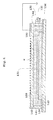
- Figure 1 is a schematic sectional view of a radiation detector according to Embodiment.
- Figure 2 is a block diagram showing an equivalent circuit of Figure 1 .
- Figure 3 is a plan view of the circuit.
- a direct conversion type radiation detector will be described by way of example.
- the radiation detector 30 of the Embodiment includes a radiation sensitive type semiconductor thick film 31 in which carriers are generated upon incidence of radiation such as X-rays, a voltage application electrode 32 provided on a surface of the semiconductor thick film 31, carrier collection electrodes 33 provided on a rear face opposite to a radiation incident side of the semiconductor thick film 31, capacitors Ca for electric charge accumulation to accumulate the carriers collected to the carrier collection electrodes 33, and thin film transistors (TFT) Tr, acting as switch elements for fetching the electric charges, that are OFF (cutoff) in normal times to fetch the electric charges accumulated in the capacitors Ca.
- This embodiment has the semiconductor thick film 31 formed of a radiation sensitive material to generate carriers upon incidence of radiation.
- the semiconductor thick film 31 may be of a light sensitive material to generate carriers upon incidence of light.
- the semiconductor thick film 31 corresponds to the conversion layer in this invention, and the voltage application electrode 32 to the voltage application electrode in this invention.
- the radiation detector 30 further includes data lines 34 connected to sources of the thin film transistors Tr and gate lines 35 connected to gates of the thin film transistors Tr.
- the voltage application electrode 32, semiconductor thick film 31, carrier collecting electrodes 33, capacitors Ca, thin film transistors Tr, data lines 34, and gate lines 35 are laminated on an insulating substrate 36.
- the insulating substrate 36 is formed, for example, of a glass substrate.
- each of the capacitors Ca and thin film transistors Tr mentioned above is connected to each of numerous carrier collecting electrodes 33 arranged in a two-dimensional matrix of row and columns (e.g. 1,024 x 1,024.) These carrier collection electrodes 33, capacitors Ca, and thin film transistors Tr each separately formed to act as detecting elements DU.
- the voltage application electrode 32 is formed entirely as a common electrode of all the detecting elements DU.
- two or more data lines 34 mentioned above are arranged in parallel in a horizontal direction (X), and two or more gate lines 35 mentioned above in parallel in a longitudinal direction (Y), as also shown in Figure 3 .
- Each of the data lines 34 and gate lines 35 is connected to each detecting element DU.
- the data lines 34 are connected to a multiplexer 38 via an electric charge-voltage conversion group (amplifier) 37, and the gate lines 35 are connected to a gate driver 39.
- an arrangement number of the detecting elements DU is not limited to 1,024 x 1,024 as mentioned above. The arrangement number may be modified for use in accordance with embodiments. Consequently, the number of the detecting elements DU may be one.
- the detecting elements DU are patterned on the insulating substrate 36 in a two-dimensional matrix arrangement.
- the insulating substrate 36 with the detecting elements DU patterned thereon is also called an "active matrix substrate.”
- the insulating substrate 36 with the detecting elements DU patterned thereon corresponds to the read out substrate in this invention.
- the electric charge-voltage conversion group (amplifier) 37 and multiplexer 38 are placed on a flexible substrate (not shown) formed of an elastomer, in turn, from the insulating substrate 36 side.
- the flexible substrate is electrically connected to the data lines 34 (see Figure 1 ) formed on the insulating substrate 36 as minute charge signal lines.
- the data lines 34 and gate line 35 are installed, using thin film formation techniques with vacuum evaporation methods or pattern techniques with photolithographic methods, and the thin film transistors Tr, capacitors Ca, carrier collection electrodes 33, semiconductor thick film 31, and voltage application electrode 32, are laminated in turn.
- the semiconductor that forms the semiconductor thick film 31 may be selected as appropriate depending on applications or electric strengths, as exemplified by amorphous semiconductors or polycrystalline semiconductors, etc.
- the material from which the semiconductor thick film 31 is made is not particularly limited, as is exemplified by selenium (Se).
- the radiation detector is of a direct conversion type, and thus the semiconductor thick film 31 is formed of amorphous selenium.
- an insulating frame 41 formed of glass is erected around the radiation detector 30 formed of the semiconductor thick films 31. and insulating substrate 36, etc., with an insulating plate 42 formed of glass placed thereon.
- An insulating resin 43 is poured into a space between the semiconductor thick film 31 or voltage application electrode 32 and the insulating plate 42 for mold sealing.
- An molding structure 44 is configured by the insulating frame 41, plate 42, and resin 43. The molding structure 44 covers and protects the semiconductor thick film 31 and voltage application electrode 32 via the insulating resin 43.
- the molding structure 44 corresponds to the molding structure in this invention.
- Figure 4 is a schematic sectional view of a conventional radiation detector for comparison with Figure 1 .
- Figure 4 has a radiation detector 130 corresponding to the radiation detector 30 of Figure 1 , a semiconductor thick film 131 corresponding to the semiconductor thick film 31 of Figure 1 , a voltage application electrode 132 corresponding to the voltage application electrode 32 of Figure 1 , data lines 134 corresponding to the data lines 34 of Figure 1 , an insulating substrate 136 corresponding to the insulating substrate 36 of Figure 1 , a frame 141 corresponding to the frame 41 of Figure 1 , a plate 142 corresponding to the plate 42 of Figure 1 , a resin 143 corresponding to the resin 43 of Figure 1 , and a molding structure 144 corresponding to the molding structure 44 of Figure 1 .
- Figure 4 shows an improved radiation detector of patent document 2 mentioned above.
- the Embodiment differs from the conventional art in its having a conductive sponge 45 and conductive carbon member 46, and a lower resistance toward the incident side, as shown in Figure 1 .
- the conventional art as shown in Figure 4 , has a conductive low potential ground 150 laminated on an incident surface side of the plate 142 of the molding structure 144.
- the low potential ground 150 is grounded that is provided on a portion of minute charge signal lines in the data lines 134 for reduction in influence of static electricity. Arrangement of the low potential ground 150 realizes removal of the static electricity e charged in the molding structure 150 as mentioned above. In Figure 4 , however, all the static electricity e occurred cannot be removed.
- the Embodiment has the planar conductive sponge 45 laminated on the incident surface of the plate 42 of the molding structure 44, as shown in Figure 1 .
- the planar conductive carbon member 46 is laminated on the incident surface side of the conductive sponge 45.
- the conductive sponge 45 has a function as a buffer.
- Each of the molding structure 44, conductive sponge 45, and conductive carbon 46 is formed such that the molding structure 44 has resistance higher than the conductive sponge 45 and the conductive sponge 45 has resistance higher than the conductive carbon member 46.
- Polyethylene foam is used, for example, as the conductive sponge 45.
- the conductive sponge 45 corresponds to the first member in this invention, and the conductive carbon member 46 to the second member in this invention.
- the molding structure 44 is preferably of resistance in a range of 1 MO to 100 MO, inclusive, the conductive sponge 45 preferably of 0.5 KO to 10 MO, inclusive, and the conductive carbon member 46 preferably of 0.1 KO to 1 MO, inclusive.
- an antistatic coating agent to be applied is atomized on for spraying and application on the incident surface of the plate 42 of the molding structure 44.
- the atomized antistatic coating agent include model "FC-172 FINE ESD coat” (production of Fine Chemical Japan Co., Ltd.) that contains zinc oxide, antimony oxidation, silicone resin, isopropanol, 1-butanol, and carbon dioxide gas. It is high pressurized with carbon dioxide gas for spraying to be applied on the incident surface of the plate 42 of the molding structure 44, thereby forming an antistatic coating film 44a.
- the antistatic coating film 44a corresponds to the object to be applied in this invention.
- frequencies of an application process may just be determined such that the molding structure has resistance within a range of 1 MO to 100 MO, inclusive, as mentioned above, in consideration of resistance, area, or thickness of a material used as a substrate (the plate 42 formed of a glass in Embodiment), or surface resistance of the antistatic coating agent, etc.
- additional coats of the antistatic coating agent is made by a spray that is represented by model "FC-172 FINE ESD coat", applying after drying it once is preferable.
- the conductive carbon 46 is contacted with a tape of low specific resistance, such as a copper (Cu) tape, that is grounded.
- a tape of low specific resistance such as a copper (Cu) tape
- Radiation to be detected enters with a high bias voltage V A (for example, around several hundreds V to several tens kV) applied to the voltage application electrode 32.
- V A for example, around several hundreds V to several tens kV
- Incidence of radiation leads to generation of carriers, and the carriers are accumulated as charge information in the capacitors Ca for accumulating electric charges.
- the gate lines 35 are selected in accordance with scanning signals for fetching signals from the gate driver 39, and the detecting elements DU connected to the selected gate lines 35 are selectively specified.
- the electric charges accumulated in the capacitors Ca of the specified detecting elements DU are read out into the data lines 34 via the thin film transistors Tr that turned into ON state with the signals from the selected gate lines 35.
- Each detecting element DU is addressed in accordance with the scanning signals from the data lines 34 and gate lines 35 for fetching the signals.
- each detecting element DU is selected from the gate driver 39 in accordance with the scanning signals in a longitudinal (Y) direction.
- the multiplexer 38 is switched in accordance with the scanning signals in a horizontal (X) direction, and then the electric charges accumulated in the capacitors Ca of the selected detecting elements DU are sent out via the data lines 34, voltage-voltage conversion group (amplifier) 37 and multiplexer 38, in turn.
- charge information is converted into image information in an image processor (not shown) via the data lines 34, and outputted as X-ray radioscopy images.
- each of the molding structure 44, the conductive sponge 45, and the conductive carbon member 46 is formed such that the molding structure 44 to protect the semiconductor thick layer 31 and voltage application electrode 32 has the resistance higher than the conductive sponge 45 composed of the planar conductive buffer that is laminated on the incident surface side of the plate 42 of the molding structure 44, and that the conductive sponge 45 mentioned above has the resistance higher than the conductive carbon member 46 composed of the planar conductive member that is laminated on the incident surface side of the conductive sponge 45.
- Static electricity occurred in the molding structure 44 may be dissipated to the conductive sponge 45 and further to the conductive carbon member 46, using a phenomenon in which static electricity flows from a higher resistance to a lower one, thereby leading to removal of the static electricity occurred in the molding structure 44.
- the planar structure of each member results in gradual removal of the static electricity.
- the conductive sponge 45 between the molding structure 44 and the conductive carbon member 46 is a buffer, and thus improved adhesion may be realized.
- a metal thin film tape such as so-called an adhesive tape having thickness of several hundred micrometers that is formed of aluminum (Al) or copper (Cu)
- Al aluminum
- Cu copper
- the conductive sponge 45 is a buffer, and thus there is no possibility of reduction in the amount of read-out signals and concentration of the electric lines of force. In addition, there is no risk of discharges. Consequently, occurrence of the noise from the static electricity can be suppressed.
- the molding structure 44 is preferably of resistance in a range of 1 MO to 100 MO, inclusive, the conductive sponge 45 preferably of 0.5 KO to than 10 MO, inclusive, and the conductive carbon member 46 preferably of 0.1 KO to 1 MO, inclusive.
- Each resistance lower than the above range leads to a large amount of movement of the static electricity, and thus sudden changes thereof may occur.
- Each resistance higher than the above range makes it difficult to completely remove the static electricity charged. Consequently, the static electricity is likely to be constantly charged, leading to rise of the electric potential, conversely. That is, a similar phenomenon occurs as the static electricity is charged in the molding structure 44, which results in impossibility to suppress influences of the noise from the static electricity.
- the static electricity may be removed while the movement speed thereof being moderately suppressed, leading to reduction in changes of the static electricity. Consequently, occurrence of the noise may be suppressed.
- the conductive carbon member 46 is preferably grounded. With such configuration, the static electricity may be dissipated into the conductive carbon member 46 may be dissipated through the grounded portion, and noises rather than the static electricity may also be suppressed. Thus, a certain effect may be desired.
- the semiconductor thick film 31 is of a radiation sensitive type that directly converts the information on radiation into charge information (carriers), and the detector is a direct conversion type radiation detector 30 having the radiation sensitive type semiconductor thick film 31.
- a higher bias voltage for example, around several hundreds V to several tens kV
- the semiconductor thick film 31 is of a radiation sensitive type that directly converts the information on radiation into charge information (carriers)
- the detector is a direct conversion type radiation detector 30 having the radiation sensitive type semiconductor thick film 31.
- a higher bias voltage for example, around several hundreds V to several tens kV
- This invention may remove the static electricity in the molding structure 44 to suppress the noise from the static electricity.
- the molding structure 44 is preferably configured so as to have resistance higher than the conductive sponge 45 by atomization of the object to be applied by spraying and application thereof to the incident surface of the plate 42 of the molding structure 44.
- the radiation to be detected may enter with no block by the molding structure 44.
- a process is preferably repeated to atomize the antistatic coating agent by spraying and application thereof.
- the molding structure 44 may be configured having a specific thickness and resistance with a specific value.
- the conductive sponge 45 is formed of polyethylene foam, and thus radiation is hardly blocked. Moreover, the conductive carbon member 46 is laminated on the incident surface side of the conductive sponge 45, and similarly radiation is hardly blocked.
- the above Embodiment of this invention applies to the direct conversion type radiation detector that converts incident radiation into charge information directly through the semiconductor thick film 31 (conversion layer.)
- This invention may apply to an indirect conversion type radiation detector in which incident radiation is converted into light by the scintillator, and the light is converted into charge information by the semiconductor layer formed of a light sensitive material, when it has the voltage application electrode for applying the bias voltage to the conversion layer.
- this invention may apply to the light detector that converts incident light into charge information by the semiconductor layer formed of a light sensitive material.
- a scintillator and a semiconductor layer formed of a light sensitive material corresponds to the conversion layer in this invention.
- detecting X-rays has been described by way of example. This invention may also apply to a detector that detects gamma rays used for a nuclear medicine device, etc.
- the conductive sponge 45 has been described as the first member in this invention by way of example.
- the first member is not particularly limited, as is exemplified by the member in which an electrically conductive filler is added to a gelatinous material or elastomer, when it is a member formed of a planar conductive buffer.
- the conductive carbon member has been described as the second member in this invention as way of example.
- the second member is not particularly limited, as is exemplified by a metal rather than carbon, when it is a planar conductive member.
- the second member (the conductive carbon 46 member in Embodiment) is grounded. It is not always necessary for the second member to be grounded.
- the second material may be of low potentials.
- the object to be applied is atomized by spraying and application to the incident surface of the molding structure.
- the plate 42 (see Figure 1 ) of the molding structure may be integrally formed, for example, when the molding structure has resistance higher than the first member (the conductive sponge 45 in Embodiment.)
Landscapes
- Physics & Mathematics (AREA)
- Engineering & Computer Science (AREA)
- Power Engineering (AREA)
- General Physics & Mathematics (AREA)
- Computer Hardware Design (AREA)
- Condensed Matter Physics & Semiconductors (AREA)
- Electromagnetism (AREA)
- Microelectronics & Electronic Packaging (AREA)
- Health & Medical Sciences (AREA)
- Toxicology (AREA)
- Life Sciences & Earth Sciences (AREA)
- High Energy & Nuclear Physics (AREA)
- Molecular Biology (AREA)
- Spectroscopy & Molecular Physics (AREA)
- Measurement Of Radiation (AREA)
- Solid State Image Pick-Up Elements (AREA)
- Photometry And Measurement Of Optical Pulse Characteristics (AREA)
Abstract
Description
- This invention relates to light or radiation detectors for use in the medical, industrial, nuclear and other fields and method of manufacturing the detectors.
- An X-ray detector will be described by way of example. The X-ray detector includes an X-ray conversion layer of an X-ray sensitive type. The detector detects X-rays by converting X-rays into electric charge information with the X-ray conversion layer upon incidence of the X-rays and reading out the electric charge information converted. Since the electric charges converted from the X-rays with the X-ray conversion layer are extremely small, the electric charges need to be amplified. The extremely small electric charges may occur not only from the X-ray but also changes in static electricity. Thus, where an electric potential change occurs from static electricity with respect to signal lines such as data lines at a previous stage of an amplifier, the change in the static electricity is identified as a signal by mistake to be amplified altogether. This results in occurrence of noise. There is a technique in which dummy lines to reduce influences of such static electricity are arranged in the thin film transistor (TFT) itself, thereby suppressing noise from the static electricity (see, for example, patent document 1.)
- Here, according to a direct conversion type X-ray detector configured to convert incident radiation directly into charge information with an X-ray conversion layer, electric charges are generated with the X-ray conversion layer upon incidence of X-rays. In that case, it is necessary to apply a high bias voltage (for example, around several hundreds V to several tens kV) to the X-ray conversion layer. Electric discharge needs to be prevented for application of a high voltage. Thus, measures will be taken such as covering of the conversion layer with an insulator generally called a "molding structure." A frame is provided around the perimeter of the X-ray conversion layer or voltage application electrode, and an insulator such as a glass is placed on the frame. Subsequently, an insulating resin is poured into a space between the X-ray conversion layer or voltage application electrode and the glass for sealing. Such a configuration is general and leads to covering and protecting of the X-ray conversion layer or voltage application electrode with the insulating resin.
- No electric discharge will occur in an applying surface of the voltage application electrode covered with the insulator such as the molding structure. On the other hand, static electricity will occur in an incidence surface (i.e., an opposed surface of the applying surface) of the molding structure. Consequently, the amplifier amplifies the change in the static electricity altogether, as mentioned above, leading to occurrence of noise. Such molding structure includes a technique to remove the static electricity using a conductive member grounded instead of the glass, thereby suppressing occurrence of the noise from the static electricity (see, for example, patent document 2.)
- There is another technique in which the grounded conductive member is arranged between a photo-timer and X-ray detector for blocking of radiation noise from the photo-timer and dissipating the radiation noise through the ground (see, for example, patent document 3.)
-
JP2003-46075A1 Figure 1 ) -
JP2004-268271A1 Figure 1 ) -
JP2005-241334A1 Figures 2 ,3 ) - However, a problem arises that all static electricity occurred cannot be removed with only measure as patent document 2 mentioned above. Particularly, the applying surface of the high voltage application electrode is maintained charged, thereby gathering dust like a collector. The dust results in occurrence of the additional noise from the static electricity.
- This invention has been made regarding the state of the art noted above, and its object is to provide a light or radiation detector capable of suppressing noise from static electricity and a method of manufacturing the detector.
- This invention provides the following construction in order to achieve the above object. A light or radiation detector of this invention is a light or radiation detector to detect light or radiation, including a conversion layer to convert information on the light or radiation into charge information upon incidence of the light or radiation, a voltage application electrode to apply a bias voltage to the conversion layer, a molding structure to protect the conversion layer and the voltage application electrode, and a read-out substrate to read the charge information, the light or radiation detector further including a first member composed of a planar conductive buffer that is laminated on a side of the incident surface of the molding structure, and a second member composed of a planar conductive member that is laminated on a side of the incident surface of the first member, each of the molding structure, the first member, and the second member being formed such that the molding structure has resistance higher than the first member and the first member has resistance higher than the second member.
- According to the light or radiation detector of this invention, each of the molding structure, the first member, and the second member is formed such that the molding structure to protect the conversion layer and voltage application electrode has the resistance higher than the first member composed of the planar conductive buffer that is laminated on the (light or radiation) incident surface side of the molding structure, and that the first member mentioned above has the resistance higher than the second member composed of the planar conductive member that is laminated on the incident surface side of the first member. Static electricity occurred in the molding structure may be dissipated to the first member and further to the second member using a phenomenon in which static electricity flows from a higher resistance to a lower one, thereby leading to removal of the static electricity occurred in the molding structure. Moreover, the planar structure of each member results in gradual removal of the static electricity. Furthermore, the first member between the molding structure and second member is a buffer, and thus improved adhesion may be realized. Where a first member is composed of a thin film such as a tape, an amount of read signals slightly decreases and electric lines of force concentrate, which results in an increased risk of electric discharge. In contrast, the first member is composed of the buffer, an amount of road signals never decreases and the electric lines of force never concentrate, which leads to no risk of the electric discharge. As a result, suppression may be made of occurrence of the noise from the static electricity.
- With the light or radiation detector mentioned above, the molding structure is preferably of resistance in a range of 1 MΩ to 100 MΩ, inclusive, the first member preferably of 0.5 KΩ to 10 MΩ, inclusive, and the second member preferably of 0.1 KΩ to 1 MΩ, inclusive. Each resistance lower than the above range leads to a large amount of movement of the static electricity, and thus sudden changes thereof may occur. Each resistance higher than the above range makes it difficult to completely remove the static electricity charged. Consequently, the static electricity is likely to be constantly charged, leading to rise of the electric potentials, conversely. That is, a similar phenomenon occurs as the static electricity is charged in the molding structure, which results in impossibility to suppress influences of the noise from the static electricity. On the other hand, with each resistance within the range mentioned above, the static electricity may be removed while the movement speed thereof being moderately suppressed, leading to reduction in changes of the static electricity. Consequently, occurrence of the noise may be suppressed.
- The light or radiation detector mentioned above is preferably configured such that the second member mentioned above is grounded. With such configuration, the static electricity dissipated into the second member may be dissipated through the grounded portion, and noises rather than from the static electricity may also be suppressed.
- The light or radiation detector mentioned above is useful to apply a direct conversion type radiation detector. Specifically, the conversion layer is of a radiation sensitive type that directly converts the information on radiation into charge information, and the detector is a direct conversion type radiation detector having the radiation sensitive type conversion layer. In the direct conversion type radiation detector, a higher bias voltage (for example, around several hundreds V to several tens kV) is applied to the voltage application electrode, and therefore to the conversion layer. Consequently the static electricity is likely to be generated in the molding structure. With this invention, however, the static electricity occurred in the molding structure may be removed to suppress the noise from the static electricity.
- This invention also relates to a method of manufacturing a light or radiation detector to detect light or radiation, the detector including a conversion layer to convert information on the light or radiation into charge information upon incidence of the light or radiation, a voltage application electrode to apply a bias voltage to the conversion layer, a molding structure to protect the conversion layer and the voltage application electrode, and a read-out substrate to read the charge information, the method including the steps of laminating a first member composed of a planar conductive buffer on a side of the incident surface of the molding structure, and laminating a second member composed of a planar conductive member on a side of the incident surface of the first member, each of the molding structure, the first member, and the second member being formed such that the molding structure has resistance higher than the first member and the first member has resistance higher than the second member.
- According to the method of manufacturing the light or radiation detector of this invention, the method includes the steps of laminating the first member composed of the planar conductive buffer on the (light or radiation) incident surface side of the molding structure, and laminating the second member composed of the planar conductive member on the incident side of the first member. Moreover, each of the molding structure, the first member, and the second member is formed such that the molding structure has the resistance higher than the first member mentioned above, and that the first member has the resistance higher than the second member mentioned above. Consequently, occurrence of the noise from the static electricity may be suppressed.
- In the method of manufacturing the light or radiation detector mentioned above, the molding structure is preferably configured so as to have resistance higher than the first member by atomization of an object to be applied by spraying and application thereof to the incident surface of the molding structure. Through atomization of the object to be applied by spraying and application thereof to the incident surface of the molding structure, the light or radiation to be detected can enter with no block by the molding structure. Repeat is preferably made of a process to apply the object to be applied by spraying and application thereof. Through the repeat of the process to apply the object to be applied by spraying and application thereof, the molding structure may be configured having a specific thickness and resistance with a specific value.
- With the light or radiation detector and the method of manufacturing the detector according to this invention, each of the molding structure, the first member, and the second member is formed such that the molding structure to protect the conversion layer and voltage application electrode has the resistance higher than the first member composed of the planar conductive buffer that is laminated on the (light or radiation) incident surface side of the molding structure, and that the first member mentioned above has the resistance higher than the second member composed of the planar conductive member that is laminated on the incident surface side of the first member. Consequently, occurrence of the noise from the static electricity may be suppressed.
-
-
Figure 1 is a schematic sectional view of a radiation detector according to Embodiment; -
Figure 2 is a block diagram showing an equivalent circuit ofFigure 1 ; -
Figure 3 is a plan view of the circuit; and -
Figure 4 is a schematic sectional view of a conventional radiation detector for comparison withFigure 1 . -
- 30
- radiation detector
- 31
- semiconductor thick film
- 32
- voltage application electrode
- 36
- insulating substrate
- 44
- molding structure
- 44a
- antistatic coating film
- 45
- conductive sponge
- 46
- conductive carbon member
- Embodiment of this invention will be described in detail hereinafter with reference to the drawings.
Figure 1 is a schematic sectional view of a radiation detector according to Embodiment.Figure 2 is a block diagram showing an equivalent circuit ofFigure 1 .Figure 3 is a plan view of the circuit. In the Embodiment, a direct conversion type radiation detector will be described by way of example. - As shown in
Figures 1 and2 , theradiation detector 30 of the Embodiment includes a radiation sensitive typesemiconductor thick film 31 in which carriers are generated upon incidence of radiation such as X-rays, avoltage application electrode 32 provided on a surface of the semiconductorthick film 31,carrier collection electrodes 33 provided on a rear face opposite to a radiation incident side of the semiconductorthick film 31, capacitors Ca for electric charge accumulation to accumulate the carriers collected to thecarrier collection electrodes 33, and thin film transistors (TFT) Tr, acting as switch elements for fetching the electric charges, that are OFF (cutoff) in normal times to fetch the electric charges accumulated in the capacitors Ca. This embodiment has the semiconductorthick film 31 formed of a radiation sensitive material to generate carriers upon incidence of radiation. The semiconductorthick film 31 may be of a light sensitive material to generate carriers upon incidence of light. Here, the semiconductorthick film 31 corresponds to the conversion layer in this invention, and thevoltage application electrode 32 to the voltage application electrode in this invention. - In addition, the
radiation detector 30 further includesdata lines 34 connected to sources of the thin film transistors Tr andgate lines 35 connected to gates of the thin film transistors Tr. Thevoltage application electrode 32, semiconductorthick film 31,carrier collecting electrodes 33, capacitors Ca, thin film transistors Tr,data lines 34, andgate lines 35 are laminated on an insulatingsubstrate 36. The insulatingsubstrate 36 is formed, for example, of a glass substrate. - As shown in
Figures 2 and3 , each of the capacitors Ca and thin film transistors Tr mentioned above is connected to each of numerouscarrier collecting electrodes 33 arranged in a two-dimensional matrix of row and columns (e.g. 1,024 x 1,024.) Thesecarrier collection electrodes 33, capacitors Ca, and thin film transistors Tr each separately formed to act as detecting elements DU. Thevoltage application electrode 32 is formed entirely as a common electrode of all the detecting elements DU. As shown inFigure 3 , two ormore data lines 34 mentioned above are arranged in parallel in a horizontal direction (X), and two ormore gate lines 35 mentioned above in parallel in a longitudinal direction (Y), as also shown inFigure 3 . Each of the data lines 34 andgate lines 35 is connected to each detecting element DU. The data lines 34 are connected to amultiplexer 38 via an electric charge-voltage conversion group (amplifier) 37, and the gate lines 35 are connected to agate driver 39. Here, an arrangement number of the detecting elements DU is not limited to 1,024 x 1,024 as mentioned above. The arrangement number may be modified for use in accordance with embodiments. Consequently, the number of the detecting elements DU may be one. - The detecting elements DU are patterned on the insulating
substrate 36 in a two-dimensional matrix arrangement. The insulatingsubstrate 36 with the detecting elements DU patterned thereon is also called an "active matrix substrate." The insulatingsubstrate 36 with the detecting elements DU patterned thereon corresponds to the read out substrate in this invention. - The electric charge-voltage conversion group (amplifier) 37 and
multiplexer 38 are placed on a flexible substrate (not shown) formed of an elastomer, in turn, from the insulatingsubstrate 36 side. The flexible substrate is electrically connected to the data lines 34 (seeFigure 1 ) formed on the insulatingsubstrate 36 as minute charge signal lines. - In manufacturing the
radiation detector 30 formed of the semiconductorthick film 31 and insulatingsubstrate 36, the data lines 34 andgate line 35 are installed, using thin film formation techniques with vacuum evaporation methods or pattern techniques with photolithographic methods, and the thin film transistors Tr, capacitors Ca,carrier collection electrodes 33, semiconductorthick film 31, andvoltage application electrode 32, are laminated in turn. Here, the semiconductor that forms the semiconductorthick film 31 may be selected as appropriate depending on applications or electric strengths, as exemplified by amorphous semiconductors or polycrystalline semiconductors, etc. Moreover, the material from which the semiconductorthick film 31 is made is not particularly limited, as is exemplified by selenium (Se). In the Embodiment, the radiation detector is of a direct conversion type, and thus the semiconductorthick film 31 is formed of amorphous selenium. - As shown in
Figure 1 , for instance, an insulatingframe 41 formed of glass is erected around theradiation detector 30 formed of the semiconductorthick films 31. and insulatingsubstrate 36, etc., with an insulatingplate 42 formed of glass placed thereon. An insulatingresin 43 is poured into a space between the semiconductorthick film 31 orvoltage application electrode 32 and the insulatingplate 42 for mold sealing. Anmolding structure 44 is configured by the insulatingframe 41,plate 42, andresin 43. Themolding structure 44 covers and protects the semiconductorthick film 31 andvoltage application electrode 32 via the insulatingresin 43. Themolding structure 44 corresponds to the molding structure in this invention. - Next, description will be made of the features of the Embodiment, with reference to
Figure 1 , and toFigure 4 for comparison with the conventional art.Figure 4 is a schematic sectional view of a conventional radiation detector for comparison withFigure 1 .Figure 4 has aradiation detector 130 corresponding to theradiation detector 30 ofFigure 1 , a semiconductorthick film 131 corresponding to the semiconductorthick film 31 ofFigure 1 , avoltage application electrode 132 corresponding to thevoltage application electrode 32 ofFigure 1 ,data lines 134 corresponding to the data lines 34 ofFigure 1 , an insulatingsubstrate 136 corresponding to the insulatingsubstrate 36 ofFigure 1 , aframe 141 corresponding to theframe 41 ofFigure 1 , aplate 142 corresponding to theplate 42 ofFigure 1 , aresin 143 corresponding to theresin 43 ofFigure 1 , and amolding structure 144 corresponding to themolding structure 44 ofFigure 1 .Figure 4 shows an improved radiation detector of patent document 2 mentioned above. - The Embodiment differs from the conventional art in its having a
conductive sponge 45 andconductive carbon member 46, and a lower resistance toward the incident side, as shown inFigure 1 . The conventional art, as shown inFigure 4 , has a conductive lowpotential ground 150 laminated on an incident surface side of theplate 142 of themolding structure 144. The lowpotential ground 150 is grounded that is provided on a portion of minute charge signal lines in thedata lines 134 for reduction in influence of static electricity. Arrangement of the lowpotential ground 150 realizes removal of the static electricity e charged in themolding structure 150 as mentioned above. InFigure 4 , however, all the static electricity e occurred cannot be removed. - On the other hand, the Embodiment has the planar
conductive sponge 45 laminated on the incident surface of theplate 42 of themolding structure 44, as shown inFigure 1 . The planarconductive carbon member 46 is laminated on the incident surface side of theconductive sponge 45. Theconductive sponge 45 has a function as a buffer. Each of themolding structure 44,conductive sponge 45, andconductive carbon 46 is formed such that themolding structure 44 has resistance higher than theconductive sponge 45 and theconductive sponge 45 has resistance higher than theconductive carbon member 46. Polyethylene foam is used, for example, as theconductive sponge 45. Here, theconductive sponge 45 corresponds to the first member in this invention, and theconductive carbon member 46 to the second member in this invention. - Specifically, the
molding structure 44 is preferably of resistance in a range of 1 MO to 100 MO, inclusive, theconductive sponge 45 preferably of 0.5 KO to 10 MO, inclusive, and theconductive carbon member 46 preferably of 0.1 KO to 1 MO, inclusive. - In particular, an antistatic coating agent to be applied is atomized on for spraying and application on the incident surface of the
plate 42 of themolding structure 44. Examples of the atomized antistatic coating agent include model "FC-172 FINE ESD coat" (production of Fine Chemical Japan Co., Ltd.) that contains zinc oxide, antimony oxidation, silicone resin, isopropanol, 1-butanol, and carbon dioxide gas. It is high pressurized with carbon dioxide gas for spraying to be applied on the incident surface of theplate 42 of themolding structure 44, thereby forming an antistatic coating film 44a. The antistatic coating film 44a corresponds to the object to be applied in this invention. - Repeat is preferably made of a process to atomize the antistatic coating agent as the object to be applied by spraying and application. Where the model "FC-172 FINE ESD coat" mentioned above is applied to the substrate of an acrylic plate, once application by a spray results in formation of the antistatic coating film having thickness of approximately 1 micrometer. In addition, where the model "FC-172 FINE ESD coat" is applied to the substrate of the acrylic plate, once application by a spray results in a surface resistivity of 5 x 10⁷ Ω/□, and twice application by a spray results in a surface resistivity of 2 x 10⁷ Ω/□. Consequently, frequencies of an application process (i.e., frequencies of additional coats) may just be determined such that the molding structure has resistance within a range of 1 MO to 100 MO, inclusive, as mentioned above, in consideration of resistance, area, or thickness of a material used as a substrate (the
plate 42 formed of a glass in Embodiment), or surface resistance of the antistatic coating agent, etc. Where multiple-times application (additional coats) of the antistatic coating agent is made by a spray that is represented by model "FC-172 FINE ESD coat", applying after drying it once is preferable. - In the Embodiment, the
conductive carbon 46 is contacted with a tape of low specific resistance, such as a copper (Cu) tape, that is grounded. - Next, operations of the
radiation detector 30 will be described. Radiation to be detected enters with a high bias voltage VA (for example, around several hundreds V to several tens kV) applied to thevoltage application electrode 32. - Incidence of radiation leads to generation of carriers, and the carriers are accumulated as charge information in the capacitors Ca for accumulating electric charges. The gate lines 35 are selected in accordance with scanning signals for fetching signals from the
gate driver 39, and the detecting elements DU connected to the selectedgate lines 35 are selectively specified. The electric charges accumulated in the capacitors Ca of the specified detecting elements DU are read out into the data lines 34 via the thin film transistors Tr that turned into ON state with the signals from the selected gate lines 35. - Each detecting element DU is addressed in accordance with the scanning signals from the data lines 34 and
gate lines 35 for fetching the signals. When the scanning signals for fetching the signals are sent into themultiplexer 38 andgate driver 39, each detecting element DU is selected from thegate driver 39 in accordance with the scanning signals in a longitudinal (Y) direction. Subsequently, themultiplexer 38 is switched in accordance with the scanning signals in a horizontal (X) direction, and then the electric charges accumulated in the capacitors Ca of the selected detecting elements DU are sent out via the data lines 34, voltage-voltage conversion group (amplifier) 37 andmultiplexer 38, in turn. - For instance, where the
radiation detector 30 according to the Embodiment is used for detecting fluoroscopy X-ray images with fluoroscopic X-ray apparatus, charge information is converted into image information in an image processor (not shown) via the data lines 34, and outputted as X-ray radioscopy images. - With the
radiation detector 30 with the above configuration according to the Embodiment, each of themolding structure 44, theconductive sponge 45, and theconductive carbon member 46 is formed such that themolding structure 44 to protect the semiconductorthick layer 31 andvoltage application electrode 32 has the resistance higher than theconductive sponge 45 composed of the planar conductive buffer that is laminated on the incident surface side of theplate 42 of themolding structure 44, and that theconductive sponge 45 mentioned above has the resistance higher than theconductive carbon member 46 composed of the planar conductive member that is laminated on the incident surface side of theconductive sponge 45. - Static electricity occurred in the
molding structure 44 may be dissipated to theconductive sponge 45 and further to theconductive carbon member 46, using a phenomenon in which static electricity flows from a higher resistance to a lower one, thereby leading to removal of the static electricity occurred in themolding structure 44. Moreover, the planar structure of each member (theplate 42 of themolding structure 44,conductive sponge 45, and conductive carbon member 46) results in gradual removal of the static electricity. Furthermore, theconductive sponge 45 between themolding structure 44 and theconductive carbon member 46 is a buffer, and thus improved adhesion may be realized. Here, where a metal thin film tape, such as so-called an adhesive tape having thickness of several hundred micrometers that is formed of aluminum (Al) or copper (Cu), is used instead of theconductive sponge 45, the amount of the incident X-rays decays, thereby leading to not only slight reduction in the amount of read-out signals but also increased risk of discharge due to concentration of the electric lines of force. In contrast, theconductive sponge 45 is a buffer, and thus there is no possibility of reduction in the amount of read-out signals and concentration of the electric lines of force. In addition, there is no risk of discharges. Consequently, occurrence of the noise from the static electricity can be suppressed. - In the Embodiment, the
molding structure 44 is preferably of resistance in a range of 1 MO to 100 MO, inclusive, theconductive sponge 45 preferably of 0.5 KO to than 10 MO, inclusive, and theconductive carbon member 46 preferably of 0.1 KO to 1 MO, inclusive. Each resistance lower than the above range leads to a large amount of movement of the static electricity, and thus sudden changes thereof may occur. Each resistance higher than the above range makes it difficult to completely remove the static electricity charged. Consequently, the static electricity is likely to be constantly charged, leading to rise of the electric potential, conversely. That is, a similar phenomenon occurs as the static electricity is charged in themolding structure 44, which results in impossibility to suppress influences of the noise from the static electricity. On the other hand, with each resistance within the range mentioned above, the static electricity may be removed while the movement speed thereof being moderately suppressed, leading to reduction in changes of the static electricity. Consequently, occurrence of the noise may be suppressed. - In the Embodiment, the
conductive carbon member 46 is preferably grounded. With such configuration, the static electricity may be dissipated into theconductive carbon member 46 may be dissipated through the grounded portion, and noises rather than the static electricity may also be suppressed. Thus, a certain effect may be desired. - It is useful to apply a direct conversion
type radiation detector 30 as in the Embodiment. Specifically, the semiconductorthick film 31 is of a radiation sensitive type that directly converts the information on radiation into charge information (carriers), and the detector is a direct conversiontype radiation detector 30 having the radiation sensitive typesemiconductor thick film 31. In the direct conversiontype radiation detector 30, a higher bias voltage (for example, around several hundreds V to several tens kV) is applied to thevoltage application electrode 32, and therefore to the semiconductorthick film 31. Consequently the static electricity is likely to be generated in themolding structure 44. This invention, however, may remove the static electricity in themolding structure 44 to suppress the noise from the static electricity. - In the Embodiment, the
molding structure 44 is preferably configured so as to have resistance higher than theconductive sponge 45 by atomization of the object to be applied by spraying and application thereof to the incident surface of theplate 42 of themolding structure 44. Through atomization of the object to be applied by spraying and application thereof to the incident surface of theplate 42 of themolding structure 44, the radiation to be detected may enter with no block by themolding structure 44. A process is preferably repeated to atomize the antistatic coating agent by spraying and application thereof. Through repeat of the process to atomize the object to be applied by spraying and application thereof, themolding structure 44 may be configured having a specific thickness and resistance with a specific value. - The
conductive sponge 45 is formed of polyethylene foam, and thus radiation is hardly blocked. Moreover, theconductive carbon member 46 is laminated on the incident surface side of theconductive sponge 45, and similarly radiation is hardly blocked. - This invention is not limited to the foregoing embodiment, but may be modified as follows.
- (1) The above Embodiment of this invention applies to the direct conversion type radiation detector that converts incident radiation into charge information directly through the semiconductor thick film 31 (conversion layer.) This invention may apply to an indirect conversion type radiation detector in which incident radiation is converted into light by the scintillator, and the light is converted into charge information by the semiconductor layer formed of a light sensitive material, when it has the voltage application electrode for applying the bias voltage to the conversion layer. Moreover, this invention may apply to the light detector that converts incident light into charge information by the semiconductor layer formed of a light sensitive material. In the indirect conversion type radiation detector, a scintillator and a semiconductor layer formed of a light sensitive material corresponds to the conversion layer in this invention.
- (2) In the Embodiment mentioned above, detecting X-rays has been described by way of example. This invention may also apply to a detector that detects gamma rays used for a nuclear medicine device, etc.
- (3) In the above Embodiment, the
conductive sponge 45 has been described as the first member in this invention by way of example. The first member is not particularly limited, as is exemplified by the member in which an electrically conductive filler is added to a gelatinous material or elastomer, when it is a member formed of a planar conductive buffer. - (4) In the above Embodiment, the conductive carbon member has been described as the second member in this invention as way of example. The second member is not particularly limited, as is exemplified by a metal rather than carbon, when it is a planar conductive member.
- (5) In the above Embodiment, the second member (the
conductive carbon 46 member in Embodiment) is grounded. It is not always necessary for the second member to be grounded. The second material may be of low potentials. - (6) In the above Embodiment, the object to be applied is atomized by spraying and application to the incident surface of the molding structure. The plate 42 (see
Figure 1 ) of the molding structure may be integrally formed, for example, when the molding structure has resistance higher than the first member (theconductive sponge 45 in Embodiment.)
Claims (7)
- A light or radiation detector to detect light or radiation, comprising a conversion layer to convert information on the light or radiation into charge information upon incidence of the light or radiation, a voltage application electrode to apply a bias voltage to the conversion layer, a molding structure to protect the conversion layer and the voltage application electrode, and a read-out substrate to read the charge information, the light or radiation detector further comprising a first member composed of a planar conductive buffer that is laminated on a side of the incident surface of the molding structure, and a second member composed of a planar conductive member that is laminated on a side of the incident surface of the first member, each of the molding structure, the first member, and the second member being formed such that the molding structure has resistance higher than the first member and the first member has resistance higher than the second member.
- The light or radiation detector according to Claim 1, wherein the molding structure is of resistance in a range of 1 MΩ to 100 MΩ, inclusive, the first member is of resistance in a range of 0.5 KΩ to 10 MΩ, inclusive, and the second member is of resistance in a range of 0.1 KΩ to 1 MΩ, inclusive.
- The light or radiation detector according to Claim 1 or Claim 2, wherein the second member is grounded.
- The light or radiation detector according to any one of Claim 1 to Claim 3, wherein the conversion layer is of a radiation sensitive type that directly converts the information on radiation into charge information, and the detector is a direct conversion type radiation detector having the radiation sensitive type conversion layer.
- A method of manufacturing a light or radiation detector to detect light or radiation, the detector comprising a conversion layer to convert information on the light or radiation into charge information upon incidence of the light or radiation, a voltage application electrode to apply a bias voltage to the conversion layer, a molding structure to protect the conversion layer and the voltage application electrode, and a read-out substrate to read the charge information, the method including the steps of laminating a first member composed of a planar conductive buffer on a side of the incident surface of the molding structure, and laminating a second member composed of a planar conductive member on a side of the incident surface of the first member, each of the molding structure, the first member, and the second member being formed such that the molding structure has resistance higher than the first member and the first member has resistance higher than the second member.
- The method of manufacturing the light or radiation detector according to Claim 5, wherein the molding structure is configured so as to have resistance higher than the first member by atomization of an object to be applied by spraying and application thereof to the incident surface of the molding structure.
- The method of manufacturing the light or radiation detector according to Claim 6, wherein the molding structure is configured so as to have resistance higher than the first member through repeat of a process to apply the object to be applied by spraying and application thereof.
Applications Claiming Priority (1)
| Application Number | Priority Date | Filing Date | Title |
|---|---|---|---|
| PCT/JP2007/070609 WO2009054042A1 (en) | 2007-10-23 | 2007-10-23 | Light or radiation detector, and method for manufacturing the same |
Publications (3)
| Publication Number | Publication Date |
|---|---|
| EP2209021A1 true EP2209021A1 (en) | 2010-07-21 |
| EP2209021A4 EP2209021A4 (en) | 2011-02-16 |
| EP2209021B1 EP2209021B1 (en) | 2011-12-14 |
Family
ID=40579152
Family Applications (1)
| Application Number | Title | Priority Date | Filing Date |
|---|---|---|---|
| EP07830343A Not-in-force EP2209021B1 (en) | 2007-10-23 | 2007-10-23 | Light or radiation detector, and method for manufacturing the same |
Country Status (7)
| Country | Link |
|---|---|
| US (1) | US8357909B2 (en) |
| EP (1) | EP2209021B1 (en) |
| JP (1) | JP4569712B2 (en) |
| CN (1) | CN101688919B (en) |
| AT (1) | ATE537467T1 (en) |
| HR (1) | HRP20100286B1 (en) |
| WO (1) | WO2009054042A1 (en) |
Families Citing this family (5)
| Publication number | Priority date | Publication date | Assignee | Title |
|---|---|---|---|---|
| WO2010070759A1 (en) * | 2008-12-18 | 2010-06-24 | 株式会社島津製作所 | Method for manufacturing optical matrix device |
| JP5694892B2 (en) * | 2011-10-19 | 2015-04-01 | 富士フイルム株式会社 | Radiation imaging equipment |
| US10481280B2 (en) * | 2016-07-07 | 2019-11-19 | Canon Kabushiki Kaisha | Radiation detecting apparatus, radiation detecting system, and manufacturing method for radiation detecting apparatus |
| JP6377101B2 (en) * | 2016-07-07 | 2018-08-22 | キヤノン株式会社 | Radiation detection apparatus and radiation detection system |
| JP7292868B2 (en) * | 2018-12-18 | 2023-06-19 | キヤノン株式会社 | Detector |
Citations (1)
| Publication number | Priority date | Publication date | Assignee | Title |
|---|---|---|---|---|
| US6885005B2 (en) * | 2001-10-22 | 2005-04-26 | Shimadzu Corporation | Radiation detector |
Family Cites Families (10)
| Publication number | Priority date | Publication date | Assignee | Title |
|---|---|---|---|---|
| JP3737343B2 (en) * | 1999-09-08 | 2006-01-18 | シャープ株式会社 | 2D image detector |
| US6681992B2 (en) * | 2000-08-03 | 2004-01-27 | Tomomi Iihama | Image reading apparatus |
| JP3678162B2 (en) * | 2001-04-12 | 2005-08-03 | 株式会社島津製作所 | Radiation detector |
| JP4280024B2 (en) | 2001-04-23 | 2009-06-17 | 株式会社東芝 | X-ray flat panel detector |
| JP4211435B2 (en) * | 2002-08-30 | 2009-01-21 | 株式会社島津製作所 | Radiation detector |
| JP3861829B2 (en) | 2003-03-05 | 2006-12-27 | ブラザー工業株式会社 | Recording media cassette |
| JP2005241334A (en) | 2004-02-25 | 2005-09-08 | Shimadzu Corp | Radiation detection instrument |
| US20050184244A1 (en) * | 2004-02-25 | 2005-08-25 | Shimadzu Corporation | Radiation detector and light or radiation detector |
| JP2005268271A (en) * | 2004-03-16 | 2005-09-29 | Shimadzu Corp | Two-dimensional detector for light or radiation |
| JP2007139604A (en) * | 2005-11-18 | 2007-06-07 | Konica Minolta Medical & Graphic Inc | Scintillator plate for radiation |
-
2007
- 2007-10-23 US US12/738,315 patent/US8357909B2/en not_active Expired - Fee Related
- 2007-10-23 WO PCT/JP2007/070609 patent/WO2009054042A1/en active Application Filing
- 2007-10-23 CN CN2007800535033A patent/CN101688919B/en not_active Expired - Fee Related
- 2007-10-23 AT AT07830343T patent/ATE537467T1/en active
- 2007-10-23 JP JP2009537846A patent/JP4569712B2/en active Active
- 2007-10-23 EP EP07830343A patent/EP2209021B1/en not_active Not-in-force
-
2010
- 2010-05-21 HR HRP20100286AA patent/HRP20100286B1/en not_active IP Right Cessation
Patent Citations (1)
| Publication number | Priority date | Publication date | Assignee | Title |
|---|---|---|---|---|
| US6885005B2 (en) * | 2001-10-22 | 2005-04-26 | Shimadzu Corporation | Radiation detector |
Non-Patent Citations (1)
| Title |
|---|
| See also references of WO2009054042A1 * |
Also Published As
| Publication number | Publication date |
|---|---|
| CN101688919A (en) | 2010-03-31 |
| JP4569712B2 (en) | 2010-10-27 |
| US8357909B2 (en) | 2013-01-22 |
| EP2209021B1 (en) | 2011-12-14 |
| HRP20100286B1 (en) | 2013-03-31 |
| JPWO2009054042A1 (en) | 2011-03-03 |
| EP2209021A4 (en) | 2011-02-16 |
| CN101688919B (en) | 2012-10-17 |
| ATE537467T1 (en) | 2011-12-15 |
| HRP20100286A2 (en) | 2010-09-30 |
| US20100243893A1 (en) | 2010-09-30 |
| WO2009054042A1 (en) | 2009-04-30 |
Similar Documents
| Publication | Publication Date | Title |
|---|---|---|
| JP3932857B2 (en) | Radiation detector | |
| KR100691463B1 (en) | Radiological image pickup apparatus | |
| KR100624026B1 (en) | Radiation detector | |
| US8039809B2 (en) | Sensor panel and image detecting device | |
| EP2209021B1 (en) | Light or radiation detector, and method for manufacturing the same | |
| US6075248A (en) | Direct radiographic imaging panel with shielding electrode | |
| US20110174957A1 (en) | Radiation detection element | |
| US6495817B1 (en) | Radiation detecting apparatus having an electrodeless region | |
| US20050184244A1 (en) | Radiation detector and light or radiation detector | |
| US20110121189A1 (en) | Radiation detector | |
| CN102144175B (en) | Radiation detector | |
| US20080087834A1 (en) | Radiation image detector | |
| US20120056287A1 (en) | Dispositif de detection de rayonnement et procede de fabrication | |
| US8552429B2 (en) | Proximity charge sensing for semiconductor detectors | |
| JP2005268271A (en) | Two-dimensional detector for light or radiation | |
| EP4235226A1 (en) | Radiation detector and detection method | |
| JP2002168958A (en) | Radiation detector assembly and medical image diagnosis device | |
| US7928401B2 (en) | Radiation detecting system | |
| US8154100B2 (en) | Electromagnetic wave detecting element | |
| Lee et al. | Direct-conversion imaging panel having a charge transport layer with controlled time constant | |
| JP2008021985A (en) | Radiation detecting device | |
| JP2009085938A (en) | Image detector |
Legal Events
| Date | Code | Title | Description |
|---|---|---|---|
| PUAI | Public reference made under article 153(3) epc to a published international application that has entered the european phase |
Free format text: ORIGINAL CODE: 0009012 |
|
| 17P | Request for examination filed |
Effective date: 20100512 |
|
| AK | Designated contracting states |
Kind code of ref document: A1 Designated state(s): AT BE BG CH CY CZ DE DK EE ES FI FR GB GR HU IE IS IT LI LT LU LV MC MT NL PL PT RO SE SI SK TR |
|
| AX | Request for extension of the european patent |
Extension state: AL BA HR MK RS |
|
| DAX | Request for extension of the european patent (deleted) | ||
| A4 | Supplementary search report drawn up and despatched |
Effective date: 20110119 |
|
| RIC1 | Information provided on ipc code assigned before grant |
Ipc: G01T 1/24 20060101AFI20090518BHEP Ipc: H01L 27/14 20060101ALI20110113BHEP Ipc: H01L 27/146 20060101ALI20110113BHEP |
|
| GRAP | Despatch of communication of intention to grant a patent |
Free format text: ORIGINAL CODE: EPIDOSNIGR1 |
|
| RIC1 | Information provided on ipc code assigned before grant |
Ipc: H01L 27/14 20060101ALI20110524BHEP Ipc: H01L 27/146 20060101ALI20110524BHEP Ipc: G01T 1/24 20060101AFI20110524BHEP |
|
| GRAS | Grant fee paid |
Free format text: ORIGINAL CODE: EPIDOSNIGR3 |
|
| GRAA | (expected) grant |
Free format text: ORIGINAL CODE: 0009210 |
|
| AK | Designated contracting states |
Kind code of ref document: B1 Designated state(s): AT BE BG CH CY CZ DE DK EE ES FI FR GB GR HU IE IS IT LI LT LU LV MC MT NL PL PT RO SE SI SK TR |
|
| REG | Reference to a national code |
Ref country code: GB Ref legal event code: FG4D |
|
| REG | Reference to a national code |
Ref country code: CH Ref legal event code: EP |
|
| REG | Reference to a national code |
Ref country code: NL Ref legal event code: T3 Ref country code: IE Ref legal event code: FG4D |
|
| REG | Reference to a national code |
Ref country code: DE Ref legal event code: R096 Ref document number: 602007019411 Country of ref document: DE Effective date: 20120308 |
|
| PG25 | Lapsed in a contracting state [announced via postgrant information from national office to epo] |
Ref country code: LT Free format text: LAPSE BECAUSE OF FAILURE TO SUBMIT A TRANSLATION OF THE DESCRIPTION OR TO PAY THE FEE WITHIN THE PRESCRIBED TIME-LIMIT Effective date: 20111214 |
|
| LTIE | Lt: invalidation of european patent or patent extension |
Effective date: 20111214 |
|
| PG25 | Lapsed in a contracting state [announced via postgrant information from national office to epo] |
Ref country code: LV Free format text: LAPSE BECAUSE OF FAILURE TO SUBMIT A TRANSLATION OF THE DESCRIPTION OR TO PAY THE FEE WITHIN THE PRESCRIBED TIME-LIMIT Effective date: 20111214 Ref country code: GR Free format text: LAPSE BECAUSE OF FAILURE TO SUBMIT A TRANSLATION OF THE DESCRIPTION OR TO PAY THE FEE WITHIN THE PRESCRIBED TIME-LIMIT Effective date: 20120315 Ref country code: SE Free format text: LAPSE BECAUSE OF FAILURE TO SUBMIT A TRANSLATION OF THE DESCRIPTION OR TO PAY THE FEE WITHIN THE PRESCRIBED TIME-LIMIT Effective date: 20111214 Ref country code: SI Free format text: LAPSE BECAUSE OF FAILURE TO SUBMIT A TRANSLATION OF THE DESCRIPTION OR TO PAY THE FEE WITHIN THE PRESCRIBED TIME-LIMIT Effective date: 20111214 |
|
| PG25 | Lapsed in a contracting state [announced via postgrant information from national office to epo] |
Ref country code: CY Free format text: LAPSE BECAUSE OF FAILURE TO SUBMIT A TRANSLATION OF THE DESCRIPTION OR TO PAY THE FEE WITHIN THE PRESCRIBED TIME-LIMIT Effective date: 20111214 Ref country code: BE Free format text: LAPSE BECAUSE OF FAILURE TO SUBMIT A TRANSLATION OF THE DESCRIPTION OR TO PAY THE FEE WITHIN THE PRESCRIBED TIME-LIMIT Effective date: 20111214 |
|
| PG25 | Lapsed in a contracting state [announced via postgrant information from national office to epo] |
Ref country code: CZ Free format text: LAPSE BECAUSE OF FAILURE TO SUBMIT A TRANSLATION OF THE DESCRIPTION OR TO PAY THE FEE WITHIN THE PRESCRIBED TIME-LIMIT Effective date: 20111214 Ref country code: SK Free format text: LAPSE BECAUSE OF FAILURE TO SUBMIT A TRANSLATION OF THE DESCRIPTION OR TO PAY THE FEE WITHIN THE PRESCRIBED TIME-LIMIT Effective date: 20111214 Ref country code: EE Free format text: LAPSE BECAUSE OF FAILURE TO SUBMIT A TRANSLATION OF THE DESCRIPTION OR TO PAY THE FEE WITHIN THE PRESCRIBED TIME-LIMIT Effective date: 20111214 Ref country code: IS Free format text: LAPSE BECAUSE OF FAILURE TO SUBMIT A TRANSLATION OF THE DESCRIPTION OR TO PAY THE FEE WITHIN THE PRESCRIBED TIME-LIMIT Effective date: 20120414 Ref country code: BG Free format text: LAPSE BECAUSE OF FAILURE TO SUBMIT A TRANSLATION OF THE DESCRIPTION OR TO PAY THE FEE WITHIN THE PRESCRIBED TIME-LIMIT Effective date: 20120314 |
|
| PG25 | Lapsed in a contracting state [announced via postgrant information from national office to epo] |
Ref country code: RO Free format text: LAPSE BECAUSE OF FAILURE TO SUBMIT A TRANSLATION OF THE DESCRIPTION OR TO PAY THE FEE WITHIN THE PRESCRIBED TIME-LIMIT Effective date: 20111214 Ref country code: PT Free format text: LAPSE BECAUSE OF FAILURE TO SUBMIT A TRANSLATION OF THE DESCRIPTION OR TO PAY THE FEE WITHIN THE PRESCRIBED TIME-LIMIT Effective date: 20120416 Ref country code: PL Free format text: LAPSE BECAUSE OF FAILURE TO SUBMIT A TRANSLATION OF THE DESCRIPTION OR TO PAY THE FEE WITHIN THE PRESCRIBED TIME-LIMIT Effective date: 20111214 |
|
| REG | Reference to a national code |
Ref country code: AT Ref legal event code: MK05 Ref document number: 537467 Country of ref document: AT Kind code of ref document: T Effective date: 20111214 |
|
| PLBE | No opposition filed within time limit |
Free format text: ORIGINAL CODE: 0009261 |
|
| STAA | Information on the status of an ep patent application or granted ep patent |
Free format text: STATUS: NO OPPOSITION FILED WITHIN TIME LIMIT |
|
| PG25 | Lapsed in a contracting state [announced via postgrant information from national office to epo] |
Ref country code: DK Free format text: LAPSE BECAUSE OF FAILURE TO SUBMIT A TRANSLATION OF THE DESCRIPTION OR TO PAY THE FEE WITHIN THE PRESCRIBED TIME-LIMIT Effective date: 20111214 |
|
| 26N | No opposition filed |
Effective date: 20120917 |
|
| PG25 | Lapsed in a contracting state [announced via postgrant information from national office to epo] |
Ref country code: IT Free format text: LAPSE BECAUSE OF FAILURE TO SUBMIT A TRANSLATION OF THE DESCRIPTION OR TO PAY THE FEE WITHIN THE PRESCRIBED TIME-LIMIT Effective date: 20111214 |
|
| REG | Reference to a national code |
Ref country code: DE Ref legal event code: R097 Ref document number: 602007019411 Country of ref document: DE Effective date: 20120917 |
|
| PG25 | Lapsed in a contracting state [announced via postgrant information from national office to epo] |
Ref country code: AT Free format text: LAPSE BECAUSE OF FAILURE TO SUBMIT A TRANSLATION OF THE DESCRIPTION OR TO PAY THE FEE WITHIN THE PRESCRIBED TIME-LIMIT Effective date: 20111214 |
|
| REG | Reference to a national code |
Ref country code: DE Ref legal event code: R082 Ref document number: 602007019411 Country of ref document: DE Representative=s name: KILIAN KILIAN & PARTNER MBB PATENTANWAELTE, DE Ref country code: DE Ref legal event code: R082 Ref document number: 602007019411 Country of ref document: DE Representative=s name: KILIAN KILIAN & PARTNER, DE |
|
| PG25 | Lapsed in a contracting state [announced via postgrant information from national office to epo] |
Ref country code: ES Free format text: LAPSE BECAUSE OF FAILURE TO SUBMIT A TRANSLATION OF THE DESCRIPTION OR TO PAY THE FEE WITHIN THE PRESCRIBED TIME-LIMIT Effective date: 20120325 |
|
| PG25 | Lapsed in a contracting state [announced via postgrant information from national office to epo] |
Ref country code: MC Free format text: LAPSE BECAUSE OF NON-PAYMENT OF DUE FEES Effective date: 20121031 |
|
| REG | Reference to a national code |
Ref country code: CH Ref legal event code: PL |
|
| GBPC | Gb: european patent ceased through non-payment of renewal fee |
Effective date: 20121023 |
|
| PG25 | Lapsed in a contracting state [announced via postgrant information from national office to epo] |
Ref country code: FI Free format text: LAPSE BECAUSE OF FAILURE TO SUBMIT A TRANSLATION OF THE DESCRIPTION OR TO PAY THE FEE WITHIN THE PRESCRIBED TIME-LIMIT Effective date: 20111214 |
|
| REG | Reference to a national code |
Ref country code: IE Ref legal event code: MM4A |
|
| PG25 | Lapsed in a contracting state [announced via postgrant information from national office to epo] |
Ref country code: IE Free format text: LAPSE BECAUSE OF NON-PAYMENT OF DUE FEES Effective date: 20121023 Ref country code: LI Free format text: LAPSE BECAUSE OF NON-PAYMENT OF DUE FEES Effective date: 20121031 Ref country code: CH Free format text: LAPSE BECAUSE OF NON-PAYMENT OF DUE FEES Effective date: 20121031 Ref country code: GB Free format text: LAPSE BECAUSE OF NON-PAYMENT OF DUE FEES Effective date: 20121023 |
|
| PG25 | Lapsed in a contracting state [announced via postgrant information from national office to epo] |
Ref country code: MT Free format text: LAPSE BECAUSE OF FAILURE TO SUBMIT A TRANSLATION OF THE DESCRIPTION OR TO PAY THE FEE WITHIN THE PRESCRIBED TIME-LIMIT Effective date: 20111214 |
|
| PG25 | Lapsed in a contracting state [announced via postgrant information from national office to epo] |
Ref country code: TR Free format text: LAPSE BECAUSE OF FAILURE TO SUBMIT A TRANSLATION OF THE DESCRIPTION OR TO PAY THE FEE WITHIN THE PRESCRIBED TIME-LIMIT Effective date: 20111214 |
|
| PG25 | Lapsed in a contracting state [announced via postgrant information from national office to epo] |
Ref country code: LU Free format text: LAPSE BECAUSE OF NON-PAYMENT OF DUE FEES Effective date: 20121023 |
|
| PG25 | Lapsed in a contracting state [announced via postgrant information from national office to epo] |
Ref country code: HU Free format text: LAPSE BECAUSE OF FAILURE TO SUBMIT A TRANSLATION OF THE DESCRIPTION OR TO PAY THE FEE WITHIN THE PRESCRIBED TIME-LIMIT Effective date: 20071023 |
|
| REG | Reference to a national code |
Ref country code: FR Ref legal event code: PLFP Year of fee payment: 9 |
|
| PGFP | Annual fee paid to national office [announced via postgrant information from national office to epo] |
Ref country code: FR Payment date: 20150908 Year of fee payment: 9 |
|
| PGFP | Annual fee paid to national office [announced via postgrant information from national office to epo] |
Ref country code: DE Payment date: 20151020 Year of fee payment: 9 |
|
| PGFP | Annual fee paid to national office [announced via postgrant information from national office to epo] |
Ref country code: NL Payment date: 20150909 Year of fee payment: 9 |
|
| REG | Reference to a national code |
Ref country code: DE Ref legal event code: R119 Ref document number: 602007019411 Country of ref document: DE |
|
| REG | Reference to a national code |
Ref country code: NL Ref legal event code: MM Effective date: 20161101 |
|
| REG | Reference to a national code |
Ref country code: FR Ref legal event code: ST Effective date: 20170630 |
|
| PG25 | Lapsed in a contracting state [announced via postgrant information from national office to epo] |
Ref country code: FR Free format text: LAPSE BECAUSE OF NON-PAYMENT OF DUE FEES Effective date: 20161102 Ref country code: DE Free format text: LAPSE BECAUSE OF NON-PAYMENT OF DUE FEES Effective date: 20170503 |
|
| PG25 | Lapsed in a contracting state [announced via postgrant information from national office to epo] |
Ref country code: NL Free format text: LAPSE BECAUSE OF NON-PAYMENT OF DUE FEES Effective date: 20161101 |