EP2208930A2 - Manufacturing method of heater tube of glow plug and glow plug - Google Patents
Manufacturing method of heater tube of glow plug and glow plug Download PDFInfo
- Publication number
- EP2208930A2 EP2208930A2 EP10250011A EP10250011A EP2208930A2 EP 2208930 A2 EP2208930 A2 EP 2208930A2 EP 10250011 A EP10250011 A EP 10250011A EP 10250011 A EP10250011 A EP 10250011A EP 2208930 A2 EP2208930 A2 EP 2208930A2
- Authority
- EP
- European Patent Office
- Prior art keywords
- heater tube
- forming
- blank material
- hole
- heater
- Prior art date
- Legal status (The legal status is an assumption and is not a legal conclusion. Google has not performed a legal analysis and makes no representation as to the accuracy of the status listed.)
- Withdrawn
Links
- 238000004519 manufacturing process Methods 0.000 title claims description 20
- 239000000463 material Substances 0.000 claims abstract description 114
- 238000010409 ironing Methods 0.000 claims abstract description 41
- 238000000034 method Methods 0.000 claims abstract description 25
- 230000020169 heat generation Effects 0.000 claims abstract description 22
- 238000003466 welding Methods 0.000 abstract description 15
- 238000005520 cutting process Methods 0.000 description 7
- 239000002184 metal Substances 0.000 description 7
- 229910052751 metal Inorganic materials 0.000 description 7
- 238000010273 cold forging Methods 0.000 description 3
- XEEYBQQBJWHFJM-UHFFFAOYSA-N Iron Chemical compound [Fe] XEEYBQQBJWHFJM-UHFFFAOYSA-N 0.000 description 2
- 230000000694 effects Effects 0.000 description 2
- 238000003754 machining Methods 0.000 description 2
- 238000003825 pressing Methods 0.000 description 2
- 229910001209 Low-carbon steel Inorganic materials 0.000 description 1
- 230000002411 adverse Effects 0.000 description 1
- 230000015572 biosynthetic process Effects 0.000 description 1
- 239000000470 constituent Substances 0.000 description 1
- 230000008602 contraction Effects 0.000 description 1
- 238000007796 conventional method Methods 0.000 description 1
- 230000006866 deterioration Effects 0.000 description 1
- 238000005242 forging Methods 0.000 description 1
- 238000010438 heat treatment Methods 0.000 description 1
- 238000003780 insertion Methods 0.000 description 1
- 230000037431 insertion Effects 0.000 description 1
- 229910052742 iron Inorganic materials 0.000 description 1
- 238000002844 melting Methods 0.000 description 1
- 230000008018 melting Effects 0.000 description 1
- 239000000843 powder Substances 0.000 description 1
- 239000004575 stone Substances 0.000 description 1
Images



Classifications
-
- F—MECHANICAL ENGINEERING; LIGHTING; HEATING; WEAPONS; BLASTING
- F23—COMBUSTION APPARATUS; COMBUSTION PROCESSES
- F23Q—IGNITION; EXTINGUISHING-DEVICES
- F23Q7/00—Incandescent ignition; Igniters using electrically-produced heat, e.g. lighters for cigarettes; Electrically-heated glowing plugs
- F23Q7/001—Glowing plugs for internal-combustion engines
- F23Q2007/004—Manufacturing or assembling methods
Definitions
- the present invention relates to a glow plug used for, for example, pre-heating for facilitating startup of a diesel engine, and more particularly to a method of manufacturing a heater tube (hereinafter may be simply referred to as a "tube"), which is a constituent part of such a glow plug, and to a glow plug.
- a heater tube hereinafter may be simply referred to as a "tube"
- FIG. 5 shows a heater element 11, which partially constitutes a glow plug 10, and also schematically shows the structure of the element 11 by a partially sectioned enlarged view thereof.
- This heater element 11 is composed of a heater tube 31 having a cylindrical straight tube portion 21 and a closed hemispherical portion 30 provided at the front end of the straight tube portion 21; a heat generation coil (hereinafter may be simply referred to as a "coil”) 41 which is formed of metal having a high melting point and is disposed within the heater tube 31; and an unillustrated insulating filling material (e.g., MgO powder).
- the heat generation coil 41 is welded to the hemispherical portion 30 at the front end (lower end in FIG. 5 ), and extends rearward (toward the upper end in FIG. 5 ).
- a heater tube which partially constitutes the heater element 11 and in which the heat generation coil 41 is accommodated is manufactured from an iron-based metal tube (in general, a circular tube formed of low carbon steel; a blank tube) through a plurality of press steps (cold forging steps).
- This production method through press working is a cold forging process, which is basically the same as that employed in a production method for forming a tubular glow plug body (housing) (see, for example, Patent Document 1).
- a heater tube before the heat generation coil 41 is accommodated therein is formed as follows. As shown in the left-end drawing (1) of FIG.
- a starting blank material (a straight circular tube having a constant transverse cross section; hereinafter may be simply referred to as a "blank material)) 20 having a predetermined length.
- a front end (lower end in FIG. 6 ) of the blank material is drawn step by step in a plurality of press steps.
- a heater tube post-forming product 20k shown in the right-end drawing (4) of FIG. 6 is obtained.
- the heater tube post-forming product 20k has a tapered-off portion 33 at the front end thereof.
- a coil 41 is disposed within the heater tube post-forming product 20k having the shape shown the left-end drawing (4) of FIG.
- a typical method of manufacturing the above-described heater tube post-forming product 20k from the blank material 20 is to draw the front end of the blank material 20 step by step through a plurality of (e.g., 10) press working steps (drawing steps) as shown in FIG. 6 .
- some intermediate formed products are omitted.
- a die 101 as shown in FIG. 8 is used.
- the left-hand drawing of FIG. 8 is a cross sectional view showing a die used in an intermediate press step (e.g., the fourth press step) and press working performed by use of the die.
- each of such dies has a forming hole 121 in which a blank material (in-process product) can be loaded (inserted) and which has, on the front end side thereof (the lower end side in FIG 8 ), a forming surface (inner surface for drawing) 131 corresponding to the drawing amount (drawing step) of the front end of the heater tube.
- a blank material 20 is loaded into the forming hole 121 of the die 101 from the rear side (the upper side in FIG. 8 ), and is pressed.
- a mandrel (pin) 201 whose front end surface is formed in accordance with the drawing amount at the front end of the blank material is typically inserted into the interior (hole) of the blank material from the rear side.
- a cylindrical tubular sleeve punch 301 which has a transverse cross section approximately the same as that of the blank material 20 and is fitted onto the mandrel 201, is coaxially inserted into the forming hole 121, so that the front end of the sleeve punch 301 moves the rear end of the blank material 20 frontward over a predetermined stroke to thereby press (apply pressure to) the blank material 20 frontward.
- the front end of the blank material 20 undergoes a predetermined draw-forming in each press step. In this manner, the front end of the blank material 20 is drawn step by step through use of the dies fabricated for the respective press steps.
- the blank material 20 is formed into the heater tube post-forming product 20k by use of a die 101 fabricated such that the heater tube post-forming product 20k has a desired front end shape.
- the diameter of the straight hole portion of the forming hole 121 of each die 101 is set such that the blank material 20 to be pressed can be inserted into the straight hole portion in a substantially clearance-free state
- the diameter of the mandrel 201 is set such that the mandrel 201 can be inserted into the blank material 20 in a substantially clearance-free state.
- the front end of the forming hole 121 of the die 101 has a hemispherical forming surface 131 corresponding to the outer surface of the front end of the heater tube post-forming product 20k shown in the right-end drawing of FIG. 6 . Further, at the center of the front end of the forming hole 121, there is provided a cylindrical hole 141 whose diameter is smaller than the outer diameter of the straight tube portion 21 of the heater tube 31.
- the cylindrical hole 141 extends frontward from the front end of the forming hole 121, and is used to form the projecting mouth portion 35 projecting frontward from the front end of the tapered-off portion 33 of the heater tube post-forming product 20k shown in the right-end drawing of FIG 6 . That is, as a result of forming the front end of the forming hole 121 into the above-described shape, the hemispherical, tapered-off portion 33, which is not closed, is formed at the front end of the finally formed heater tube post-forming product 20k as shown in the right-end drawing of FIG. 6 . Further, the projecting mouth portion 35, which projects frontward by a predetermined projection length L1, is formed at the front end of the tapered-off portion 33.
- the distal end 42 of the coil 41 is inserted into the projecting mouth portion 35 at the front end of the tapered-off portion 33.
- the distal end 42 of the coil 41 is then positioned and welded to the projecting mouth portion 35.
- the front end of the heater tube post-forming product 20k has the above-mentioned projecting mouth portion 35.
- the projecting mouth portion 35 is molten and solidified, whereby the opening thereof is closed, and the tapered-off portion 33 assumes a hemispherical shape.
- Patent Document 1 Japanese Patent Publication ( kokoku ) No. H2-6412
- the blank material (starting blank material) 20 used for the above-described press steps is one obtained through cutting a cylindrical tube to a predetermined length.
- a cutting operation in some cases, only an upper-side dimensional tolerance is specified, with a lower-side dimensional tolerance fixed to 0.
- the length of the blank material 20 varies within a range of 0.5 mm.
- the blank material is compressed in the axial direction by an amount corresponding to the predetermined stroke set for each step.
- the front end of the blank material 20 is pushed into the cylindrical hole 141 provided at the front end of the forming hole 121 of the die, whereby the projecting mouth portion 35 is finally formed at the front end of the blank material. Accordingly, in the case where the length of the blank material is longer than a reference dimension, the front end of the blank material is pushed into the cylindrical hole 141 at the front end of the forming hole 121 of the die 101 by a greater amount corresponding to the difference between the length of the blank material and the reference dimension.
- the length L2 of the heater tube post-forming product 20k is maintained at a predetermined dimension (set dimension).
- the projection length L1 of the projecting mouth portion 35 at the front end of the tapered-off portion 33 becomes longer than a reference dimension; and the greater the dimensional variation, the greater the projection length L1. That is, the heater tube post-forming product 20k formed through the final press step has a variation in the projection length L1 of the projecting mouth portion 35, which variation corresponds to a variation in the length of the blank material.
- the blank material 20 is longer than the reference dimension and the projection length L1 of the projecting mouth portion 35 at the formed tapered-off portion 33 is excessively large, a problem of improper welding between the projecting mouth portion 35 and the distal end 42 of the coil 41 occurs.
- the projection length L1 of the projecting mouth portion 35 at the tapered-off portion 33 is excessively large, the base material (a projecting wall portion of the projecting mouth portion 35) fails to be sufficiently melted, whereby the amount of molten metal (melt) becomes insufficient (excessively small), and welding failure occurs.
- the hemispherical portion 30 of the heater element 11 has a wall thickness greater than a desired thickness, or fails to assume a desired hemispherical shape and accuracy. This leads to deterioration of the temperature performance of a glow plug finished product.
- a first object of the present invention is to maintain at a predetermined amount the projection length of a projecting mouth portion projecting frontward from a tapered-off portion at the front end of a heater tube, to thereby prevent occurrence of welding failure, which would otherwise occur when a front end of a heat generation coil disposed within the heater tube is welded to the projecting mouth portion.
- a second object of the present invention is to provide a heater tube which prevents generation of a variation in the temperature performance among glow plug finished products.
- the present invention which achieves the above-described objects is as follows.
- the invention described in claim 1 is a method of manufacturing a heater tube for a glow plug which includes a straight tube portion, a tapered-off portion provided at a front end of the straight tube portion, and a projecting mouth portion projecting frontward from a front end of the tapered-off portion, the method comprising a plurality of press steps in each of which a tubular blank material is loaded into a forming hole of a die, and is pressed frontward via a rear end of the blank material, the method being characterized in that at least a die used in the final press step is formed such that a straight hole portion of a forming hole of the die has a diameter greater than an outer diameter of a straight tube portion of a heater tube finished product; the die formed such that the straight hole portion of the forming hole of the die has a diameter greater than the outer diameter of the straight tube portion of the heater tube finished product is provided with a support member which is disposed on a front end side of
- the invention described in claim 2 is a method of manufacturing a heater tube for a glow plug which includes a straight tube portion, a tapered-off portion provided at a front end of the straight tube portion, and a projecting mouth portion projecting frontward from a front end of the tapered-off portion, the method comprising a plurality of press steps in each of which a tubular blank material is loaded into a forming hole of a die, and is pressed frontward via a rear end of the blank material, the method being characterized in that each of dies used in a plurality of press steps including the final press step is formed such that a straight hole portion of a forming hole of the die has a diameter greater than an outer diameter of a straight tube portion of a heater tube finished product; each die formed such that the straight hole portion of the forming hole of the die has a diameter greater than the outer diameter of the straight tube portion of the heater tube finished product is provided with a support member which is disposed on a front end side of the forming hole so as to support a front
- the invention described in claim 3, which depends from the invention described in claim 2, is characterized in that the plurality of press steps including the final press step are successive press steps which are performed continuously.
- a mandrel pin
- a mandrel is desirably inserted into the tubular blank material when the blank material is loaded into the forming hole of the die, and is pressed frontward via the rear end of the blank material in the axial direction.
- a mandrel is desirably inserted into the straight tube portion of the heater tube post-forming product when the heater tube post-forming product is ironed.
- a heater tube in a process before being formed into the heater tube finished product will also be referred to as a "heater tube in-process product.”
- the "heater tube post-forming product formed from the blank material through press forming in the final press step” means a heater tube in-process product which has undergone the plurality of press steps and is immediately before undergoing ironing work in the ironing step.
- the forming holes of the dies which are used in the respective steps in order to obtain the heater tube post-forming product are formed such that the above-described heater tube; i.e., that having a tapered-off portion at the front end of a straight tube portion thereof, and a projecting mouth portion projecting frontward from the front end of the tapered-off portion, is finally obtained as a heater tube post-forming product. Therefore, the forming hole is made slightly different among the dies used in the plurality of press steps so that the straight tube portion is pressed in the axial direction so as to plastically deform the front end of the straight tube portion step by step, and the heater tube post-forming product is finally obtained.
- this forming hole has a straight hole portion, and a forming surface which is formed at the front end of the straight hole portion and adapted to form the tapered-off portion and the projecting mouth portion in each forming step.
- the forming hole is identical with the forming holes of dies used in the conventional manufacturing method. That is, the straight hole portions of the dies used in the present invention are identical with the forming holes of dies used in the conventional manufacturing method, except for the diameter of the straight hole portions.
- the diameter of the straight hole portion of the forming hole of each die is made greater than the outer diameter of the straight tube portion of the heater tube finished product by an amount determined such that a tubular starting blank material obtained through cutting is allowed to expand radially outward so as to absorb an excessive volume of the blank material corresponding to a cutting tolerance (error) set for the entire length of the blank material.
- means for removing an unnecessary portion in the present invention include end machining by means of a cutting tool (cutting), cutting-off by means of a cutting-off tool, and grinding by means of a grinding stone.
- the invention described in Claim 4 is a glow plug which includes a heater element disposed such that a front end of the heater element projects from a front end of the glow plug, wherein the heater element is configured such that a heat generation coil is disposed in a heater tube manufactured by a manufacturing method according to any one of claims 1 to 3, a front end of the heat generation coil is inserted into the projecting mouth portion projecting frontward from the front end of the tapered-off portion of the heater tube, and the front end of the heat generation coil is welded to the projecting mouth portion.
- the diameter of the straight hole portion of the forming hole of at least the die used in the final press step is made greater than the outer diameter of the straight tube portion of the heater tube finished product.
- a support member is disposed so as to support the front end of the blank material.
- the straight tube portion expands radially outward and has an outer diameter greater than the outer diameter of the straight tube portion of the heater tube finished product. Accordingly, in the present invention, even when a blank material whose overall length is greater than the reference dimension is contained in blank materials to be used, the projection length of the projecting mouth portion is prevented from becoming excessively large, whereby there can be obtained heater tube in-process products in which the projection length of the projecting mouth portion is maintained at the predetermined projection length.
- the outer diameter of the straight tube portion is adjusted (corrected) to a predetermined dimension.
- the overall length of the ironed heater tube is greater than the overall length as measured before the heater tube is ironed.
- a rear-end unnecessary portion of the straight tube portion of the heater tube is removed, whereby the overall length is adjusted to the predetermined dimension.
- the straight tube portion becomes thinner and longer as a result of ironing, the overall length of the heater tube in-process product in this stage is longer than the reference dimension.
- the shapes and dimensions of the tapered-off portion and the projecting mouth portion projecting from the front end thereof are substantially free from the influence of the ironing work, and the accuracy attained before the ironing work is maintained as is. Accordingly, after the ironing work, while a front end portion of the heater tube in-process product is used as a reference, a rear end portion (unnecessary portion) of the straight tube portion, which is longer than the reference dimension, is cut (removed) by means of, for example, cutting, whereby heater tubes having a desired dimensional accuracy can be obtained.
- the tip end of a coil is inserted into the projecting mouth portion at the front end of the tapered-off portion of a heater tube manufactured as described above, positioned, and welded to the projecting mouth portion, the amount of molten metal produced during the welding is prevented from becoming excessively small or excessively large, whereby occurrence of a failure associated with the welding can be prevented. Accordingly, there can be effectively prevented generation of a variation in temperature performance among glow plugs (finished products) each including a heater element composed of a heater tube manufactured by the method of the present invention and a heat generation coil welded thereto. Further, according to the present manufacturing method, since an unnecessary portion of the straight tube portion is removed, there can be attained an effect that the maximum allowable dimension set for the length of a straight tube (starting blank material) can be increased.
- a glow plug including a heater element composed of a heater tube manufactured by the above-described method and a heat generation coil welded thereto has a consistent temperature performance.
- a starting blank material (may be simply referred to as the "blank material"), and a tube formed through press steps are assumed to be identical with those shown at the left-hand and right-hand ends of FIG. 6 .
- a heater tube post-forming product (a formed heater tube intermediate to be subjected to an ironing step) 20k is formed from the starting blank material through 11 press steps.
- the starting blank material is assumed to have a length equal to a maximum allowable dimension.
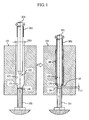
- dies similar to the conventional dies are used so as to draw the front end portion of the blank material 20 step by step in the first press step to the third press step; and a die 101 shown in FIGS. 1 and 2 and having a forming hole 121 peculiar to the present invention is used in the fourth press step to the eleventh press step (final press step).
- a heater tube in-process product i.e., a blank material in the forming process
- the dies 101 used in these steps have the same basic structure as the conventional dies 101 except for the following points.
- a support member 151 is disposed on the front end side of the forming hole 121 of each die 101 so as to support, in the corresponding press step, the front end of the blank material (the blank material to be pressed in press steps other than the final press step) 20, to thereby maintain the projection length L1 of the projecting mouth portion 35 of the blank material 20 at a predetermined projection length.
- the dies 101 slightly differ from each other in terms of the shape of the front end of the forming hole 121 in accordance with the drawing amount of the front end of the blank material. Therefore, here, the dies 101 used in the fourth press step shown in FIG.
- each of these dies 101 includes a mandrel 201 which is inserted into the blank material 20, and a sleeve punch 301 which axially presses the blank material 20 via its rear end.
- This die 101 has the forming hole 121 which further draws, by an adequate degree, the front end of the blank material (see FIG 6 (3)) 20 having undergone press forming in the third press step.
- This forming hole 121 has a straight hole portion 123, and a forming surface having a tapered-off shape (hereinafter may be referred to as the "tapered-off forming surface) 131 which is provided at the front end of the straight hole portion 123 and has a shape corresponding to the degree of drawing in the fourth press step.
- the diameter (bore diameter) D21 of the straight hole portion 123 is determined such that the blank material 20 having undergone the press working in the third press step can be loaded into the straight hole portion 123, and the diameter D21 is greater than the outer diameter D1 of a straight tube portion 21 of a heater tube finished product (see the right end of FIG. 4 ) 20fby, for example, 0.15 mm. Accordingly, this forming hole 121 is formed such that, when the blank material 20 is pressed in the axial direction, the outer diameter of the straight tube portion 21 of the blank material 20 can become greater than the outer diameter D1 of the straight tube portion 21 of the heater tube finished product 20f.
- a cylindrical hole 141 whose diameter is smaller than the diameter D21 is formed such that it further extends frontward from the front end of the forming hole 121 so as to form, through press forming, the cylindrical projecting mouth portion 35, which projects frontward from the front end of the tapered-off portion 33 of the blank material 20.
- the rod-shaped (circular columnar) support member 151 is inserted into the cylindrical hole 141 to be movable in the vertical direction. Notably, this support member 151 is inserted into the cylindrical hole 141 in a substantially clearance-free state.
- the support member 151 is positioned in relation to the die 101 such that, when the blank material 20 is pressed in the present step, the front end of the support member 151 is maintained at a predetermined position so as to maintain the projection length L1 of the projecting mouth portion 35 at a predetermined length (stop the projecting mouth portion 35 at a predetermined position).
- the dies and support members used in the fifth press step and subsequent steps are also configured in the same manner as the die 101 and the support member 151 shown in FIG. 1 .
- the tapered-off shape of the front end of the straight hole portion of the forming hole of each die is determined in accordance with the degree of drawing in each step such that the shape and dimension of the tapered-off front end of the straight hole portion become closer to those of the tapered-off portion and the projecting mouth portion of the finished product step by step.
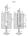
- FIG. 2 is a pair of views showing the die 101 used in the eleventh press step (final step) and a press step performed by use of the die.
- the die 101 and the support member 151 used in the eleventh press step are formed such that the tapered-off portion 33 at the front end of the blank material 20 having undergone the press forming in the tenth press step and the projecting mouth portion 35 projecting forward from the front end of the tapered-off portion 33 are formed to finally have a predetermined diameter and a predetermined projection length L1.
- the diameter (bore diameter) D21 of the straight hole portion 123 of the die used in the eleventh press step is greater than the outer diameter D1 of the straight tube portion 21 of the heater tube finished product 20f.
- the fourth press step in which the blank material 20 having undergone the press forming in the previous step is press-formed by use of the die 101 shown in FIG. 1 .
- the mandrel 201 and the sleeve punch 301 of the die 101 shown in FIG. 1 are moved upward, and the blank material 20 is loaded into the forming hole 121 of the die 101 from the rear end side (the upper end side in FIG. 1 ) such that the front end of the blank material 20 is located on the front-end side of the forming hole 121 (see the right-hand drawing of FIG. 1 ).
- the mandrel 201 is inserted into the blank material 20.
- this mandrel 201 has a diameter which enables its insertion into the blank material 20 in a substantially clearance-free state, and the front end of the mandrel 201 is rounded in accordance with the drawing amount of the front end of the blank material 20.
- a cylindrical tubular sleeve punch 301 which has a transverse cross section approximately the same as that of the blank material 20 and is fitted onto the mandrel 201, is coaxially inserted into the forming hole 121, so that a front-end portion of the sleeve punch 301 moves the rear end of the blank material 20 frontward over a predetermined stroke to thereby press (apply pressure to) the blank material 20 frontward.
- the front end of the blank material 20 is drawn to follow the shape of the tapered-off forming surface 131 at the front end of the forming hole 121, whereby a predetermined drawn shape to be imparted in this step is imparted to the front end of the blank material 20.
- the overall length of the used blank material 20 is longer than the reference dimension.
- the rod-shaped support member 151 is disposed in the cylindrical hole 141 of the die 101 as described above, the projection length L1 of the projecting mouth portion 35 at the front end of the blank material 20 is maintained at a predetermined length set for this step.
- the straight tube portion 21 of the blank material 20 is allowed to expand in the radial direction in the straight hole portion 123 during the pressing. Therefore, the straight tube portion 21 expands and deforms such that its outer diameter increases by an amount corresponding to the difference between the length of the starting blank material 20 and the reference dimension.
- the blank material 20 having undergone the press forming in the fourth press step is similarly press-formed in the fifth press step and subsequent steps by use of the dies for the respective press steps.
- the press forming is performed by use of the die 101 shown in FIG. 2 . That is, in this eleventh press step, the front end of the blank material 20 is drawn to follow the shape of the tapered-off forming surface 131 at the front end of the forming hole 121, whereby the front end of the blank material 20 is formed into a tapered-off portion 33 having a predetermined shape and dimensions.
- the rod-shaped support member 151 is disposed in the cylindrical hole 141 of the die 101 as described above.
- the projection length L1 of the projecting mouth portion 35 at the front end of the blank material (heater tube post-forming product) 20k having undergone this final press step is maintained at the predetermined projection length.
- the straight tube portion 21 of the heater tube post-forming product 20k is allowed to expand in the radial direction within the straight hole portion 123 to thereby have an outer diameter greater than the outer diameter D1 of the heater tube finished product 20f.
- the straight tube portion 21 of the heater tube post-forming product 20k having undergone the final press step has an outer diameter D3 (see FIG 3 and the left-end drawing of FIG 4 ), which is greater than the outer diameter D1 indicated by lines in FIG 3 having alternate long and two short dashes.
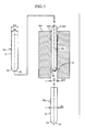
- a different mandrel 212 is inserted into the straight tube portion 21 of the heater tube post-forming product 20k having undergone the press-forming in the final press step.
- the heater tube post-forming product 20k with the mandrel 212 inserted thereinto is passed through an ironing hole 403 formed in an ironing die 401, starting from its front end.
- This ironing hole 403 is a cylindrical hole having a diameter D24 which can reduce the diameter of the straight tube portion 21 of the heater tube post-forming product 20k to the outer diameter D1 of the final heater tube finished product 20f.
- the diameter D24 is made equal to D1.
- the straight tube portion 21 of the heater tube (ironed product) 20s having undergone the ironing step has an adjusted (corrected) outer diameter equal to the outer diameter D1 of the final heater tube finished product 20f.
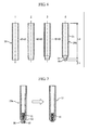
- FIG. 4 shows the heater tube post-forming product 20k which is to be ironed and which has an expanded straight tube portion 21; and the drawing on the right side thereof (the center drawing) shows the ironed heater tube 20s (a heater tube in-process product).
- the ironing hole 403 of the ironing die 401 of FIG. 3 has a larger-diameter guide portion 404 formed at the inlet (an upper opening in FIG 3 ) of the ironing hole 403.
- the heater tube (ironed product) 20s having undergone the above-described ironing step has an increased overall length and an adjusted outer diameter equal to the outer diameter D1 of the final heater tube finished product 20f. That is, as shown at the center of FIG. 4 , as a result of a slight reduction in the outer diameter D1 of the straight tube portion 21, the length L2 of the straight tube portion 21 is increased from the reference dimension by a small amount (crosshatched portion) S. Thus, the straight tube portion 21 has an unnecessary portion 25. Therefore, the unnecessary portion 25, which corresponds to the small amount S and is present at the rear end of the straight tube portion 21, is removed by means of, for example, turning. As a result, as shown on the right end of FIG.
- a heater tube which has a desired dimensional accuracy not only in the outer diameter and the projection length L1 of the projecting mouth portion 35 at the front end of the tapered-off portion 33, but also in the length L2 of the straight tube portion 21 of the heater tube.
- the inner surface of a rear end portion of the heater tube is machined simultaneously.
- removal of the unnecessary portion can be performed in the same step. Since the removal of the unnecessary portion does not require a separate step, cost does not increase.
- the projecting mouth portion 35 at the front end thereof has desired dimensions.
- the heat generation coil 41 is welded to such a heater tube 20f. Specifically, as in the case shown in FIG. 7 , the distal end 42 of the heat generation coil 41 is inserted into the projecting mouth portion 35 at the front end of the tapered-off portion 33 of the heater tube 20f, positioned, and welded to the projecting mouth portion 35.
- a heater element 11 having the same structure as that shown in the enlarged view of FIG. 5 is obtained.
- the amount of molten metal produced at the time of welding is prevented from becoming excessively small or excessively large, occurrence of a failure associated with the welding; i.e., generation of an excessively large or small amount of molten metal, can be prevented. Accordingly, when a heater element 11 produced by mean of welding the heat generation coil 41 to the heater tube 20f manufactured as described above is used to assemble a glow plug (a finished product) 10 such that a front end portion of the element 11 projects from the front end of the glow plug 10 as shown in FIG. 5 , generation of a variation in temperature performance can be prevented.
- the starting blank material has a length which is equal to the reference length or less than the maximum allowable dimension, even when the straight tube portion becomes thinner and longer in the ironing step, its length does not exceed the maximum allowable dimension. Therefore, in the case of such a heater tube, no unnecessary portion is produced at the rear end of the straight tube portion, and it is clear that a step of removing the unnecessary portion is not required.
- all the dies 101 respectively used in the successive fourth to the eleventh (final) press steps are configured such that the diameter of the straight hole portion 123 of the forming hole 121 is larger than the outer diameter D1 of the straight tube portion 21 of the heater tube finished product, and the support member 151 is disposed in each of the dies 101. Therefore, the dimensional accuracy of the projecting mouth portion 35 at the front end of the tapered-off portion 33 can be maintained at a very high level.
- use of such a die is not required in all the press steps, and the present invention is not limited to the case where such a die is used in all the process steps.
- the dies excluding the die used in the final press step, may be formed such that the straight hole portions of the dies used in alternate press steps have diameters larger than the outer diameter of the straight tube portion of the heater tube finished product, and the straight hole portions of the remaining dies have smaller diameters, so long as the blank material can be loaded into the forming hole of each die.
- only the die used in the final press step may be configured such that the diameter of the straight hole portion of the forming hole is larger than the outer diameter of the straight tube portion of the heater tube finished product, and the support member may be disposed in that die only.
Landscapes
- Engineering & Computer Science (AREA)
- Chemical & Material Sciences (AREA)
- Combustion & Propulsion (AREA)
- Mechanical Engineering (AREA)
- General Engineering & Computer Science (AREA)
- Resistance Heating (AREA)
- Shaping Metal By Deep-Drawing, Or The Like (AREA)
Abstract
Description
- The present invention relates to a glow plug used for, for example, pre-heating for facilitating startup of a diesel engine, and more particularly to a method of manufacturing a heater tube (hereinafter may be simply referred to as a "tube"), which is a constituent part of such a glow plug, and to a glow plug.
-
FIG. 5 shows aheater element 11, which partially constitutes aglow plug 10, and also schematically shows the structure of theelement 11 by a partially sectioned enlarged view thereof. Thisheater element 11 is composed of aheater tube 31 having a cylindricalstraight tube portion 21 and a closedhemispherical portion 30 provided at the front end of thestraight tube portion 21; a heat generation coil (hereinafter may be simply referred to as a "coil") 41 which is formed of metal having a high melting point and is disposed within theheater tube 31; and an unillustrated insulating filling material (e.g., MgO powder). Within theheater tube 31, theheat generation coil 41 is welded to thehemispherical portion 30 at the front end (lower end inFIG. 5 ), and extends rearward (toward the upper end inFIG. 5 ). - Conventionally, a heater tube which partially constitutes the
heater element 11 and in which theheat generation coil 41 is accommodated is manufactured from an iron-based metal tube (in general, a circular tube formed of low carbon steel; a blank tube) through a plurality of press steps (cold forging steps). This production method through press working is a cold forging process, which is basically the same as that employed in a production method for forming a tubular glow plug body (housing) (see, for example, Patent Document 1). In the cold forging process, a heater tube before theheat generation coil 41 is accommodated therein is formed as follows. As shown in the left-end drawing (1) ofFIG. 6 , there is prepared a starting blank material (a straight circular tube having a constant transverse cross section; hereinafter may be simply referred to as a "blank material)) 20 having a predetermined length. A front end (lower end inFIG. 6 ) of the blank material is drawn step by step in a plurality of press steps. Finally, a heatertube post-forming product 20k shown in the right-end drawing (4) ofFIG. 6 is obtained. As shown in the drawing, the heatertube post-forming product 20k has a tapered-offportion 33 at the front end thereof. As shown in the left-hand drawing inFIG. 7 , acoil 41 is disposed within the heatertube post-forming product 20k having the shape shown the left-end drawing (4) ofFIG. 6 such that a distal end (wire end portion) 42 of thecoil 41 is positioned in a cylindrical projectingmouth portion 35 projecting from the front end of the tapered-offportion 33 of the heatertube post-forming product 20k. Subsequently, the projectingmouth portion 35 and the coildistal end 42 are welded together, whereby theheater element 11 is completed as shown in the right-hand drawing ofFIG 7 . - A typical method of manufacturing the above-described heater tube
post-forming product 20k from theblank material 20 is to draw the front end of theblank material 20 step by step through a plurality of (e.g., 10) press working steps (drawing steps) as shown inFIG. 6 .
Notably, inFIG. 6 , some intermediate formed products are omitted. In each of the steps of drawing theblank material 20, adie 101 as shown inFIG. 8 is used. The left-hand drawing ofFIG. 8 is a cross sectional view showing a die used in an intermediate press step (e.g., the fourth press step) and press working performed by use of the die. The right-hand drawing ofFIG. 8 is a cross sectional view showing a die used in the final step (e.g., the tenth press step) and press working performed by use of the die. All the dies, including dies used in other press steps (stages), basically have the same structure, except that forming holes formed in the dies are rendered different from one another in accordance with the amount of drawing at the front end to be effected in the individual step. Accordingly, each of such dies has a forminghole 121 in which a blank material (in-process product) can be loaded (inserted) and which has, on the front end side thereof (the lower end side inFIG 8 ), a forming surface (inner surface for drawing) 131 corresponding to the drawing amount (drawing step) of the front end of the heater tube. - In a press step performed by use of such a
die 101, ablank material 20 is loaded into the forminghole 121 of thedie 101 from the rear side (the upper side inFIG. 8 ), and is pressed. However, as shown inFIG. 8 , in intermediate and final press steps, a mandrel (pin) 201 whose front end surface is formed in accordance with the drawing amount at the front end of the blank material is typically inserted into the interior (hole) of the blank material from the rear side. Further, a cylindricaltubular sleeve punch 301, which has a transverse cross section approximately the same as that of theblank material 20 and is fitted onto themandrel 201, is coaxially inserted into the forminghole 121, so that the front end of thesleeve punch 301 moves the rear end of theblank material 20 frontward over a predetermined stroke to thereby press (apply pressure to) theblank material 20 frontward. Thus, the front end of theblank material 20 undergoes a predetermined draw-forming in each press step. In this manner, the front end of theblank material 20 is drawn step by step through use of the dies fabricated for the respective press steps. As shown in the right-hand drawing ofFIG 8 , in the final press step, theblank material 20 is formed into the heatertube post-forming product 20k by use of adie 101 fabricated such that the heatertube post-forming product 20k has a desired front end shape. Notably, the diameter of the straight hole portion of the forminghole 121 of eachdie 101 is set such that theblank material 20 to be pressed can be inserted into the straight hole portion in a substantially clearance-free state, and the diameter of themandrel 201 is set such that themandrel 201 can be inserted into theblank material 20 in a substantially clearance-free state. - Incidentally, since the right-hand drawing of
FIG. 8 shows adie 101 used in the final press step, the front end of the forminghole 121 of thedie 101 has a hemispherical formingsurface 131 corresponding to the outer surface of the front end of the heatertube post-forming product 20k shown in the right-end drawing ofFIG. 6 . Further, at the center of the front end of the forminghole 121, there is provided acylindrical hole 141 whose diameter is smaller than the outer diameter of thestraight tube portion 21 of theheater tube 31. Thecylindrical hole 141 extends frontward from the front end of the forminghole 121, and is used to form the projectingmouth portion 35 projecting frontward from the front end of the tapered-offportion 33 of the heater tubepost-forming product 20k shown in the right-end drawing ofFIG 6 . That is, as a result of forming the front end of the forminghole 121 into the above-described shape, the hemispherical, tapered-offportion 33, which is not closed, is formed at the front end of the finally formed heater tubepost-forming product 20k as shown in the right-end drawing ofFIG. 6 . Further, the projectingmouth portion 35, which projects frontward by a predetermined projection length L1, is formed at the front end of the tapered-offportion 33. - Conventionally, after formation of the front-end portion of the heater
tube post-forming product 20k in such a manner, as described above, thedistal end 42 of thecoil 41 is inserted into the projectingmouth portion 35 at the front end of the tapered-offportion 33. Thedistal end 42 of thecoil 41 is then positioned and welded to the projectingmouth portion 35. Notably, up to the time when theheat generation coil 41 is welded to the front end of the heatertube post-forming product 20k, the front end of the heatertube post-forming product 20k has the above-mentionedprojecting mouth portion 35. However, at the time of welding, the projectingmouth portion 35 is molten and solidified, whereby the opening thereof is closed, and the tapered-offportion 33 assumes a hemispherical shape. - [Patent Document 1] Japanese Patent Publication (kokoku) No.
H2-6412 - When the
heat generation coil 41 is welded to the inner wall surface of the front end portion of the heater tube post-forming product (the right-end drawing ofFIG. 6 ) 20k manufactured through the above-described press (forging) steps, in rare cases, the welding fails to be performed properly. Further, in some cases, the improperly performed welding adversely affects the temperature performance of a glow plug finished product. The present inventors found that such a problem occurs for the following reason. - The blank material (starting blank material) 20 used for the above-described press steps is one obtained through cutting a cylindrical tube to a predetermined length. For such a cutting operation, in some cases, only an upper-side dimensional tolerance is specified, with a lower-side dimensional tolerance fixed to 0. For example, in a case where the upper-side dimensional tolerance is +0.5, the length of the
blank material 20 varies within a range of 0.5 mm. Meanwhile, in each of the above-described press steps, the blank material is compressed in the axial direction by an amount corresponding to the predetermined stroke set for each step. Meanwhile, at least in the die used in the final step, the front end of theblank material 20 is pushed into thecylindrical hole 141 provided at the front end of the forminghole 121 of the die, whereby the projectingmouth portion 35 is finally formed at the front end of the blank material. Accordingly, in the case where the length of the blank material is longer than a reference dimension, the front end of the blank material is pushed into thecylindrical hole 141 at the front end of the forminghole 121 of thedie 101 by a greater amount corresponding to the difference between the length of the blank material and the reference dimension. Therefore, the length L2 of the heater tubepost-forming product 20k, as measured from its rear end to the front end of the hemispherical, tapered-off portion 33 (the overall length - L1; hereinafter may be referred to as the "length of the straight tube portion") is maintained at a predetermined dimension (set dimension). However, in accordance with the dimensional difference, the projection length L1 of the projectingmouth portion 35 at the front end of the tapered-offportion 33 becomes longer than a reference dimension; and the greater the dimensional variation, the greater the projection length L1. That is, the heater tubepost-forming product 20k formed through the final press step has a variation in the projection length L1 of the projectingmouth portion 35, which variation corresponds to a variation in the length of the blank material. - Conventionally, if the
blank material 20 is longer than the reference dimension and the projection length L1 of the projectingmouth portion 35 at the formed tapered-offportion 33 is excessively large, a problem of improper welding between the projectingmouth portion 35 and thedistal end 42 of thecoil 41 occurs. Specifically, when the projection length L1 of the projectingmouth portion 35 at the tapered-offportion 33 is excessively large, the base material (a projecting wall portion of the projecting mouth portion 35) fails to be sufficiently melted, whereby the amount of molten metal (melt) becomes insufficient (excessively small), and welding failure occurs. In contrast, when the entirety of the projectingmouth portion 35 whose projection length L1 is excessively large is melted, the amount (volume) of solidified melt becomes excessive (excessively large). In such a case, after welding of thecoil 41, thehemispherical portion 30 of theheater element 11 has a wall thickness greater than a desired thickness, or fails to assume a desired hemispherical shape and accuracy. This leads to deterioration of the temperature performance of a glow plug finished product. - The present invention has been accomplished in order to solve such problems. A first object of the present invention is to maintain at a predetermined amount the projection length of a projecting mouth portion projecting frontward from a tapered-off portion at the front end of a heater tube, to thereby prevent occurrence of welding failure, which would otherwise occur when a front end of a heat generation coil disposed within the heater tube is welded to the projecting mouth portion. A second object of the present invention is to provide a heater tube which prevents generation of a variation in the temperature performance among glow plug finished products.
- The present invention which achieves the above-described objects is as follows. The invention described in
claim 1 is a method of manufacturing a heater tube for a glow plug which includes a straight tube portion, a tapered-off portion provided at a front end of the straight tube portion, and a projecting mouth portion projecting frontward from a front end of the tapered-off portion, the method comprising a plurality of press steps in each of which a tubular blank material is loaded into a forming hole of a die, and is pressed frontward via a rear end of the blank material, the method being characterized in that
at least a die used in the final press step is formed such that a straight hole portion of a forming hole of the die has a diameter greater than an outer diameter of a straight tube portion of a heater tube finished product;
the die formed such that the straight hole portion of the forming hole of the die has a diameter greater than the outer diameter of the straight tube portion of the heater tube finished product is provided with a support member which is disposed on a front end side of the forming hole so as to support a front end of the blank material to thereby maintain a projection length of the projecting mouth portion at a predetermined projection length;
the blank material is pressed in a state in which the support member is provided;
a heater tube post-forming product formed from the blank material through press forming in the final press step is passed through an ironing hole of an ironing die formed such that the ironing hole has a diameter which can reduce an outer diameter of a straight tube portion of the heater tube post-forming product to an outer diameter equal to a predetermined outer diameter of the straight tube portion of the heater tube finished product, to thereby adjust the outer diameter of the straight tube portion of the heater tube post-forming product to the predetermined outer diameter; and
when an overall length of a heater tube obtained from the heater tube post-forming product through the ironing step is greater than a maximum allowable dimension, a rear-end unnecessary portion of a straight tube portion of the heater tube is removed so as to adjust the overall length to a predetermined dimension. - The invention described in
claim 2 is a method of manufacturing a heater tube for a glow plug which includes a straight tube portion, a tapered-off portion provided at a front end of the straight tube portion, and a projecting mouth portion projecting frontward from a front end of the tapered-off portion, the method comprising a plurality of press steps in each of which a tubular blank material is loaded into a forming hole of a die, and is pressed frontward via a rear end of the blank material, the method being characterized in that
each of dies used in a plurality of press steps including the final press step is formed such that a straight hole portion of a forming hole of the die has a diameter greater than an outer diameter of a straight tube portion of a heater tube finished product;
each die formed such that the straight hole portion of the forming hole of the die has a diameter greater than the outer diameter of the straight tube portion of the heater tube finished product is provided with a support member which is disposed on a front end side of the forming hole so as to support a front end of the blank material to thereby maintain a projection length of the projecting mouth portion at a predetermined projection length;
in each of the plurality of press steps, the blank material is pressed in a state in which the support member is provided;
a heater tube post-forming product formed from the blank material through press forming in the final press step is passed through an ironing hole of an ironing die formed such that the ironing hole has a diameter which can reduce an outer diameter of a straight tube portion of the heater tube post-forming product to an outer diameter equal to a predetermined outer diameter of the straight tube portion of the heater tube finished product, to thereby adjust the outer diameter of the straight tube portion of the heater tube post-forming product to the predetermined outer diameter; and
when an overall length of a heater tube obtained from the heater tube post-forming product through the ironing step is greater than a maximum allowable dimension, a rear-end unnecessary portion of a straight tube portion of the heater tube is removed so as to adjust the overall length to a predetermined dimension. - The invention described in
claim 3, which depends from the invention described inclaim 2, is characterized in that the plurality of press steps including the final press step are successive press steps which are performed continuously. Notably, in the present invention, in order to improve dimensional accuracy, a mandrel (pin) is desirably inserted into the tubular blank material when the blank material is loaded into the forming hole of the die, and is pressed frontward via the rear end of the blank material in the axial direction. Further, for the same reason, a mandrel is desirably inserted into the straight tube portion of the heater tube post-forming product when the heater tube post-forming product is ironed. Notably, in the following description, a heater tube in a process before being formed into the heater tube finished product will also be referred to as a "heater tube in-process product." In the present invention, the "heater tube post-forming product formed from the blank material through press forming in the final press step" means a heater tube in-process product which has undergone the plurality of press steps and is immediately before undergoing ironing work in the ironing step. - Further, in the present invention, the forming holes of the dies which are used in the respective steps in order to obtain the heater tube post-forming product are formed such that the above-described heater tube; i.e., that having a tapered-off portion at the front end of a straight tube portion thereof, and a projecting mouth portion projecting frontward from the front end of the tapered-off portion, is finally obtained as a heater tube post-forming product. Therefore, the forming hole is made slightly different among the dies used in the plurality of press steps so that the straight tube portion is pressed in the axial direction so as to plastically deform the front end of the straight tube portion step by step, and the heater tube post-forming product is finally obtained. However, this forming hole has a straight hole portion, and a forming surface which is formed at the front end of the straight hole portion and adapted to form the tapered-off portion and the projecting mouth portion in each forming step. The forming hole is identical with the forming holes of dies used in the conventional manufacturing method. That is, the straight hole portions of the dies used in the present invention are identical with the forming holes of dies used in the conventional manufacturing method, except for the diameter of the straight hole portions.
- Further, in the present invention, the diameter of the straight hole portion of the forming hole of each die is made greater than the outer diameter of the straight tube portion of the heater tube finished product by an amount determined such that a tubular starting blank material obtained through cutting is allowed to expand radially outward so as to absorb an excessive volume of the blank material corresponding to a cutting tolerance (error) set for the entire length of the blank material. Further, examples of means for removing an unnecessary portion in the present invention include end machining by means of a cutting tool (cutting), cutting-off by means of a cutting-off tool, and grinding by means of a grinding stone.
- The invention described in Claim 4 is a glow plug which includes a heater element disposed such that a front end of the heater element projects from a front end of the glow plug, wherein the heater element is configured such that a heat generation coil is disposed in a heater tube manufactured by a manufacturing method according to any one of
claims 1 to 3, a front end of the heat generation coil is inserted into the projecting mouth portion projecting frontward from the front end of the tapered-off portion of the heater tube, and the front end of the heat generation coil is welded to the projecting mouth portion. - In the manufacturing method of the present invention, the diameter of the straight hole portion of the forming hole of at least the die used in the final press step is made greater than the outer diameter of the straight tube portion of the heater tube finished product. Further, on the front end side of the forming hole of such a die, a support member is disposed so as to support the front end of the blank material. By virtue of this configuration, the projection length of the projecting mouth portion is maintained at a predetermined projection length. That is, even when the length of the blank material is longer than a reference dimension, the projection length of the projecting mouth portion at the front end of the blank material can be prevented from becoming longer than the predetermined projection length. As a result of contraction of the blank material in the axial direction stemming from the restriction on the projection length of the projecting mouth portion, the straight tube portion expands radially outward and has an outer diameter greater than the outer diameter of the straight tube portion of the heater tube finished product. Accordingly, in the present invention, even when a blank material whose overall length is greater than the reference dimension is contained in blank materials to be used, the projection length of the projecting mouth portion is prevented from becoming excessively large, whereby there can be obtained heater tube in-process products in which the projection length of the projecting mouth portion is maintained at the predetermined projection length.
- Further, since the blank material having undergone the final press step subsequently undergoes ironing in an ironing step as described above, the outer diameter of the straight tube portion is adjusted (corrected) to a predetermined dimension. Moreover, the overall length of the ironed heater tube is greater than the overall length as measured before the heater tube is ironed. When the overall length is greater than a maximum allowable dimension, a rear-end unnecessary portion of the straight tube portion of the heater tube is removed, whereby the overall length is adjusted to the predetermined dimension. By virtue of removal of an unnecessary portion, heater tubes which have desired dimensions, including not only the projection length of the front end projecting mouth portion, but also the length between the front end of the tapered-off portion and the rear end of the straight tube portion, can be manufactured efficiently.
- Notably, since the straight tube portion becomes thinner and longer as a result of ironing, the overall length of the heater tube in-process product in this stage is longer than the reference dimension. However, the shapes and dimensions of the tapered-off portion and the projecting mouth portion projecting from the front end thereof are substantially free from the influence of the ironing work, and the accuracy attained before the ironing work is maintained as is. Accordingly, after the ironing work, while a front end portion of the heater tube in-process product is used as a reference, a rear end portion (unnecessary portion) of the straight tube portion, which is longer than the reference dimension, is cut (removed) by means of, for example, cutting, whereby heater tubes having a desired dimensional accuracy can be obtained.
- In the case where the tip end of a coil is inserted into the projecting mouth portion at the front end of the tapered-off portion of a heater tube manufactured as described above, positioned, and welded to the projecting mouth portion, the amount of molten metal produced during the welding is prevented from becoming excessively small or excessively large, whereby occurrence of a failure associated with the welding can be prevented. Accordingly, there can be effectively prevented generation of a variation in temperature performance among glow plugs (finished products) each including a heater element composed of a heater tube manufactured by the method of the present invention and a heat generation coil welded thereto. Further, according to the present manufacturing method, since an unnecessary portion of the straight tube portion is removed, there can be attained an effect that the maximum allowable dimension set for the length of a straight tube (starting blank material) can be increased.
- As described above, in the case of the glow plug described in claim 4, when the distal end of the heat generation coil and the projecting mouth portion are welded together in the process of manufacturing the heater element, the amount of molten metal produced during the welding is prevented from becoming excessively small or excessively large, because of small variation in the projection length of the projecting mouth portion. Therefore, a glow plug including a heater element composed of a heater tube manufactured by the above-described method and a heat generation coil welded thereto has a consistent temperature performance.
-
- [
FIG. 1 ] A cross sectional view of a die used in an intermediate press step, which is used for describing a manufacturing method of the present invention, and a cross sectional view for describing a forming step performed by use of the die. - [
FIG. 2 ] A cross sectional view of a die used in a final press step, which is used for describing the manufacturing method of the present invention, and a cross sectional view for describing a forming step performed by use of the die. - [
FIG. 3 ] A cross sectional view of a die used in an ironing step, and a cross sectional view for describing a ironing step performed by use of the die. - [
FIG. 4 ] Views showing a heater tube post-forming product having undergone the final press step, a heater tube after having undergone the ironing step, and a heater tube finished product obtained through removal of a rear end (unnecessary portion) of a straight tube portion of the heater tube. - [
FIG. 5 ] A view schematically showing the structure of a glow plug and an enlarged, partially sectioned view of a heater element assembled to the glow plug. - [
FIG. 6 ] Sectional views for describing steps of forming a heater tube which partially constitutes the heater element ofFIG. 5 . - [
FIG. 7 ] Sectional views for describing steps of welding a heat generation coil to the heater tube. - [
FIG. 8 ] Sectional view showing a conventional die for forming the heater tube, and showing the state of pressing performed by use of the die. - An embodiment of the manufacturing method according to the present invention will be described in detail with reference to
FIGS. 1 to 4 . Notably, a starting blank material (may be simply referred to as the "blank material"), and a tube formed through press steps are assumed to be identical with those shown at the left-hand and right-hand ends ofFIG. 6 . However, in the present embodiment, a heater tube post-forming product (a formed heater tube intermediate to be subjected to an ironing step) 20k is formed from the starting blank material through 11 press steps. Notably, in the following description, the starting blank material is assumed to have a length equal to a maximum allowable dimension. Further, in the present embodiment, dies similar to the conventional dies are used so as to draw the front end portion of theblank material 20 step by step in the first press step to the third press step; and adie 101 shown inFIGS. 1 and2 and having a forminghole 121 peculiar to the present invention is used in the fourth press step to the eleventh press step (final press step). Notably, a heater tube in-process product (i.e., a blank material in the forming process) may also be simply referred to as the "blank material." - The dies 101 used in these steps have the same basic structure as the conventional dies 101 except for the following points. First, a
support member 151 is disposed on the front end side of the forminghole 121 of each die 101 so as to support, in the corresponding press step, the front end of the blank material (the blank material to be pressed in press steps other than the final press step) 20, to thereby maintain the projection length L1 of the projectingmouth portion 35 of theblank material 20 at a predetermined projection length. Second, the dies 101 slightly differ from each other in terms of the shape of the front end of the forminghole 121 in accordance with the drawing amount of the front end of the blank material. Therefore, here, the dies 101 used in the fourth press step shown inFIG. 1 and the eleventh step (final step) shown inFIG. 2 will be described. Notably, although the details will be described later, each of these dies 101 includes amandrel 201 which is inserted into theblank material 20, and asleeve punch 301 which axially presses theblank material 20 via its rear end. - First, the
die 101 used in the fourth press step will be described with reference toFIG 1 . This die 101 has the forminghole 121 which further draws, by an adequate degree, the front end of the blank material (seeFIG 6 (3)) 20 having undergone press forming in the third press step. This forminghole 121 has astraight hole portion 123, and a forming surface having a tapered-off shape (hereinafter may be referred to as the "tapered-off forming surface) 131 which is provided at the front end of thestraight hole portion 123 and has a shape corresponding to the degree of drawing in the fourth press step. The diameter (bore diameter) D21 of thestraight hole portion 123 is determined such that theblank material 20 having undergone the press working in the third press step can be loaded into thestraight hole portion 123, and the diameter D21 is greater than the outer diameter D1 of astraight tube portion 21 of a heater tube finished product (see the right end ofFIG. 4 ) 20fby, for example, 0.15 mm. Accordingly, this forminghole 121 is formed such that, when theblank material 20 is pressed in the axial direction, the outer diameter of thestraight tube portion 21 of theblank material 20 can become greater than the outer diameter D1 of thestraight tube portion 21 of the heater tube finishedproduct 20f. Further, at the center of the tapered-off formingsurface 131 at the front end of the forminghole 121 of thedie 101, as shown inFIG. 1 , acylindrical hole 141 whose diameter is smaller than the diameter D21 is formed such that it further extends frontward from the front end of the forminghole 121 so as to form, through press forming, the cylindrical projectingmouth portion 35, which projects frontward from the front end of the tapered-offportion 33 of theblank material 20. - The rod-shaped (circular columnar)
support member 151 is inserted into thecylindrical hole 141 to be movable in the vertical direction. Notably, thissupport member 151 is inserted into thecylindrical hole 141 in a substantially clearance-free state. Thesupport member 151 is positioned in relation to the die 101 such that, when theblank material 20 is pressed in the present step, the front end of thesupport member 151 is maintained at a predetermined position so as to maintain the projection length L1 of the projectingmouth portion 35 at a predetermined length (stop the projectingmouth portion 35 at a predetermined position). The dies and support members used in the fifth press step and subsequent steps are also configured in the same manner as thedie 101 and thesupport member 151 shown inFIG. 1 . The difference is that, as described above, the tapered-off shape of the front end of the straight hole portion of the forming hole of each die is determined in accordance with the degree of drawing in each step such that the shape and dimension of the tapered-off front end of the straight hole portion become closer to those of the tapered-off portion and the projecting mouth portion of the finished product step by step. - Further,
FIG. 2 is a pair of views showing thedie 101 used in the eleventh press step (final step) and a press step performed by use of the die. Thedie 101 and thesupport member 151 used in the eleventh press step are formed such that the tapered-offportion 33 at the front end of theblank material 20 having undergone the press forming in the tenth press step and the projectingmouth portion 35 projecting forward from the front end of the tapered-offportion 33 are formed to finally have a predetermined diameter and a predetermined projection length L1. Further, like the dies used in the press forming in the fourth press step and subsequent press steps, the diameter (bore diameter) D21 of thestraight hole portion 123 of the die used in the eleventh press step is greater than the outer diameter D1 of thestraight tube portion 21 of the heater tube finishedproduct 20f. - There will be described the fourth press step in which the
blank material 20 having undergone the press forming in the previous step is press-formed by use of the die 101 shown inFIG. 1 . Themandrel 201 and thesleeve punch 301 of the die 101 shown inFIG. 1 are moved upward, and theblank material 20 is loaded into the forminghole 121 of the die 101 from the rear end side (the upper end side inFIG. 1 ) such that the front end of theblank material 20 is located on the front-end side of the forming hole 121 (see the right-hand drawing ofFIG. 1 ). Subsequently, themandrel 201 is inserted into theblank material 20. As in the case of the conventional technique, thismandrel 201 has a diameter which enables its insertion into theblank material 20 in a substantially clearance-free state, and the front end of themandrel 201 is rounded in accordance with the drawing amount of the front end of theblank material 20. - Next, in a state in which the
blank material 20 is loaded and placed within the forminghole 121, a cylindricaltubular sleeve punch 301, which has a transverse cross section approximately the same as that of theblank material 20 and is fitted onto themandrel 201, is coaxially inserted into the forminghole 121, so that a front-end portion of thesleeve punch 301 moves the rear end of theblank material 20 frontward over a predetermined stroke to thereby press (apply pressure to) theblank material 20 frontward. Thus, the front end of theblank material 20 is drawn to follow the shape of the tapered-off formingsurface 131 at the front end of the forminghole 121, whereby a predetermined drawn shape to be imparted in this step is imparted to the front end of theblank material 20. In the present embodiment, the overall length of the usedblank material 20 is longer than the reference dimension. However, since the rod-shapedsupport member 151 is disposed in thecylindrical hole 141 of the die 101 as described above, the projection length L1 of the projectingmouth portion 35 at the front end of theblank material 20 is maintained at a predetermined length set for this step. Meanwhile, thestraight tube portion 21 of theblank material 20 is allowed to expand in the radial direction in thestraight hole portion 123 during the pressing. Therefore, thestraight tube portion 21 expands and deforms such that its outer diameter increases by an amount corresponding to the difference between the length of the startingblank material 20 and the reference dimension. - Then, the
blank material 20 having undergone the press forming in the fourth press step is similarly press-formed in the fifth press step and subsequent steps by use of the dies for the respective press steps. In the eleventh press step, which is the final press step, the press forming is performed by use of the die 101 shown inFIG. 2 . That is, in this eleventh press step, the front end of theblank material 20 is drawn to follow the shape of the tapered-off formingsurface 131 at the front end of the forminghole 121, whereby the front end of theblank material 20 is formed into a tapered-offportion 33 having a predetermined shape and dimensions. In the present embodiment, the rod-shapedsupport member 151 is disposed in thecylindrical hole 141 of the die 101 as described above. Accordingly, the projection length L1 of the projectingmouth portion 35 at the front end of the blank material (heater tube post-forming product) 20k having undergone this final press step is maintained at the predetermined projection length. Meanwhile, in this press step as well, thestraight tube portion 21 of the heatertube post-forming product 20k is allowed to expand in the radial direction within thestraight hole portion 123 to thereby have an outer diameter greater than the outer diameter D1 of the heater tube finishedproduct 20f. Accordingly, in the case where the startingblank material 20 is longer than the reference dimension, thestraight tube portion 21 of the heatertube post-forming product 20k having undergone the final press step has an outer diameter D3 (seeFIG 3 and the left-end drawing ofFIG 4 ), which is greater than the outer diameter D1 indicated by lines inFIG 3 having alternate long and two short dashes. - As shown in
FIG 3 , adifferent mandrel 212 is inserted into thestraight tube portion 21 of the heatertube post-forming product 20k having undergone the press-forming in the final press step. The heatertube post-forming product 20k with themandrel 212 inserted thereinto is passed through anironing hole 403 formed in anironing die 401, starting from its front end. Thisironing hole 403 is a cylindrical hole having a diameter D24 which can reduce the diameter of thestraight tube portion 21 of the heatertube post-forming product 20k to the outer diameter D1 of the final heater tube finishedproduct 20f. In the present example, the diameter D24 is made equal to D1. Thus, thestraight tube portion 21 of the heater tube (ironed product) 20s having undergone the ironing step has an adjusted (corrected) outer diameter equal to the outer diameter D1 of the final heater tube finishedproduct 20f. - The left-end drawing of
FIG. 4 shows the heatertube post-forming product 20k which is to be ironed and which has an expandedstraight tube portion 21; and the drawing on the right side thereof (the center drawing) shows the ironedheater tube 20s (a heater tube in-process product). Notably, theironing hole 403 of the ironing die 401 ofFIG. 3 has a larger-diameter guide portion 404 formed at the inlet (an upper opening inFIG 3 ) of theironing hole 403. - The heater tube (ironed product) 20s having undergone the above-described ironing step has an increased overall length and an adjusted outer diameter equal to the outer diameter D1 of the final heater tube finished
product 20f. That is, as shown at the center ofFIG. 4 , as a result of a slight reduction in the outer diameter D1 of thestraight tube portion 21, the length L2 of thestraight tube portion 21 is increased from the reference dimension by a small amount (crosshatched portion) S. Thus, thestraight tube portion 21 has anunnecessary portion 25. Therefore, theunnecessary portion 25, which corresponds to the small amount S and is present at the rear end of thestraight tube portion 21, is removed by means of, for example, turning. As a result, as shown on the right end ofFIG. 4 , in the present embodiment, there can be obtained a heater tube which has a desired dimensional accuracy not only in the outer diameter and the projection length L1 of the projectingmouth portion 35 at the front end of the tapered-offportion 33, but also in the length L2 of thestraight tube portion 21 of the heater tube. Notably, when necessary, the inner surface of a rear end portion of the heater tube is machined simultaneously. In the case where such machining of the inner surface of the rear end portion is required, removal of the unnecessary portion can be performed in the same step. Since the removal of the unnecessary portion does not require a separate step, cost does not increase. - That is, in the
heater tube 20f manufactured in the above-described manner, the projectingmouth portion 35 at the front end thereof has desired dimensions. Theheat generation coil 41 is welded to such aheater tube 20f. Specifically, as in the case shown inFIG. 7 , thedistal end 42 of theheat generation coil 41 is inserted into the projectingmouth portion 35 at the front end of the tapered-offportion 33 of theheater tube 20f, positioned, and welded to the projectingmouth portion 35. Thus, aheater element 11 having the same structure as that shown in the enlarged view ofFIG. 5 is obtained. Since the amount of molten metal produced at the time of welding is prevented from becoming excessively small or excessively large, occurrence of a failure associated with the welding; i.e., generation of an excessively large or small amount of molten metal, can be prevented. Accordingly, when aheater element 11 produced by mean of welding theheat generation coil 41 to theheater tube 20f manufactured as described above is used to assemble a glow plug (a finished product) 10 such that a front end portion of theelement 11 projects from the front end of theglow plug 10 as shown inFIG. 5 , generation of a variation in temperature performance can be prevented. Notably, in the case where the starting blank material has a length which is equal to the reference length or less than the maximum allowable dimension, even when the straight tube portion becomes thinner and longer in the ironing step, its length does not exceed the maximum allowable dimension. Therefore, in the case of such a heater tube, no unnecessary portion is produced at the rear end of the straight tube portion, and it is clear that a step of removing the unnecessary portion is not required. - In the above-described embodiment, all the dies 101 respectively used in the successive fourth to the eleventh (final) press steps are configured such that the diameter of the
straight hole portion 123 of the forminghole 121 is larger than the outer diameter D1 of thestraight tube portion 21 of the heater tube finished product, and thesupport member 151 is disposed in each of the dies 101. Therefore, the dimensional accuracy of the projectingmouth portion 35 at the front end of the tapered-offportion 33 can be maintained at a very high level. However, depending on the desired dimensional accuracy, use of such a die is not required in all the press steps, and the present invention is not limited to the case where such a die is used in all the process steps. The dies, excluding the die used in the final press step, may be formed such that the straight hole portions of the dies used in alternate press steps have diameters larger than the outer diameter of the straight tube portion of the heater tube finished product, and the straight hole portions of the remaining dies have smaller diameters, so long as the blank material can be loaded into the forming hole of each die. Depending on the desired dimensional accuracy and so long as forming is possible, only the die used in the final press step may be configured such that the diameter of the straight hole portion of the forming hole is larger than the outer diameter of the straight tube portion of the heater tube finished product, and the support member may be disposed in that die only. -
- 10: glow plug
- 20: blank material
- 20k: heater tube post-forming product having undergone the final press step
- 20s: heater tube having undergone the ironing step (ironed product)
- 20f: heater tube finished product
- 21: straight tube portion
- 25: unnecessary portion at the rear end of the straight tube portion
- 31: heater tube with a heat generation coil welded thereto
- 33: tapered-off portion
- 35: projecting mouth portion
- 101: die
- 121: forming hole
- 123: straight hole portion
- 151: support member
- 401: ironing die
- 403: ironing hole
- D1: outer diameter of the straight tube portion of the heater tube finished product
- D3: outer diameter of the straight tube portion of the blank material before being ironed
- D21: diameter of the straight hole portion
- L1: projection length of the projecting mouth portion
- L2: length of the straight tube portion
Claims (4)
- A method of manufacturing a heater tube for a glow plug which includes a straight tube portion, a tapered-off portion provided at a front end of the straight tube portion, and a projecting mouth portion projecting frontward from a front end of the tapered-off portion, the method comprising a plurality of press steps in each of which a tubular blank material is loaded into a forming hole of a die, and is pressed frontward via a rear end of the blank material, the method being characterized in that
at least a die used in the final press step is formed such that a straight hole portion of a forming hole of the die has a diameter greater than an outer diameter of a straight tube portion of a heater tube finished product;
the die formed such that the straight hole portion of the forming hole of the die has a diameter greater than the outer diameter of the straight tube portion of the heater tube finished product is provided with a support member which is disposed on a front end side of the forming hole so as to support a front end of the blank material to thereby maintain a projection length of the projecting mouth portion at a predetermined projection length;
the blank material is pressed in a state in which the support member is provided;
a heater tube post-forming product formed from the blank material through press forming in the final press step is passed through an ironing hole of an ironing die formed such that the ironing hole has a diameter which can reduce an outer diameter of a straight tube portion of the heater tube post-forming product to an outer diameter equal to a predetermined outer diameter of the straight tube portion of the heater tube finished product, to thereby adjust the outer diameter of the straight tube portion of the heater tube post-forming product to the predetermined outer diameter; and
when an overall length of a heater tube obtained from the heater tube post-forming product through the ironing step is greater than a maximum allowable dimension, a rear-end unnecessary portion of a straight tube portion of the heater tube is removed so as to adjust the overall length to a predetermined dimension. - A method of manufacturing a heater tube for a glow plug which includes a straight tube portion, a tapered-off portion provided at a front end of the straight tube portion, and a projecting mouth portion projecting frontward from a front end of the tapered-off portion, the method comprising a plurality of press steps in each of which a tubular blank material is loaded into a forming hole of a die, and is pressed frontward via a rear end of the blank material, the method being characterized in that
each of dies used in a plurality of press steps including the final press step is formed such that a straight hole portion of a forming hole of the die has a diameter greater than an outer diameter of a straight tube portion of a heater tube finished product;
each die formed such that the straight hole portion of the forming hole of the die has a diameter greater than the outer diameter of the straight tube portion of the heater tube finished product is provided with a support member which is disposed on a front end side of the forming hole so as to support a front end of the blank material to thereby maintain a projection length of the projecting mouth portion at a predetermined projection length;
in each of the plurality of press steps, the blank material is pressed in a state in which the support member is provided;
a heater tube post-forming product formed from the blank material through press forming in the final press step is passed through an ironing hole of an ironing die formed such that the ironing hole has a diameter which can reduce an outer diameter of a straight tube portion of the heater tube post-forming product to an outer diameter equal to a predetermined outer diameter of the straight tube portion of the heater tube finished product, to thereby adjust the outer diameter of the straight tube portion of the heater tube post-forming product to the predetermined outer diameter; and
when an overall length of a heater tube obtained from the heater tube post-forming product through the ironing step is greater than a maximum allowable dimension, a rear-end unnecessary portion of a straight tube portion of the heater tube is removed so as to adjust the overall length to a predetermined dimension. - A method of manufacturing a heater tube for a glow plug according to claim 2, wherein the plurality of press steps including the final press step are successive press steps which are performed continuously.
- A glow plug comprising a heater element disposed such that a front end of the heater element projects from a front end of the glow plug, wherein the heater element is configured such that a heat generation coil is disposed in a heater tube manufactured by a manufacturing method according to any one of claims 1 to 3, a front end of the heat generation coil is inserted into the projecting mouth portion projecting frontward from the front end of the tapered-off portion of the heater tube, and the front end of the heat generation coil is welded to the projecting mouth portion.
Applications Claiming Priority (1)
| Application Number | Priority Date | Filing Date | Title |
|---|---|---|---|
| JP2009006912A JP5170894B2 (en) | 2009-01-15 | 2009-01-15 | Method of manufacturing heater tube for glow plug and glow plug |
Publications (2)
| Publication Number | Publication Date |
|---|---|
| EP2208930A2 true EP2208930A2 (en) | 2010-07-21 |
| EP2208930A3 EP2208930A3 (en) | 2018-01-24 |
Family
ID=42111349
Family Applications (1)
| Application Number | Title | Priority Date | Filing Date |
|---|---|---|---|
| EP10250011.3A Withdrawn EP2208930A3 (en) | 2009-01-15 | 2010-01-06 | Manufacturing method of heater tube of glow plug and glow plug |
Country Status (3)
| Country | Link |
|---|---|
| EP (1) | EP2208930A3 (en) |
| JP (1) | JP5170894B2 (en) |
| KR (1) | KR101288224B1 (en) |
Families Citing this family (4)
| Publication number | Priority date | Publication date | Assignee | Title |
|---|---|---|---|---|
| KR101253752B1 (en) * | 2011-02-21 | 2013-04-23 | 주식회사 봉일금속 | Device glow plug and manufacturing method of glow-plug's tube using the same |
| US9664388B2 (en) | 2011-05-25 | 2017-05-30 | Ngk Spark Plug Co., Ltd. | Glow plug and method for manufacturing glow plug |
| KR101237886B1 (en) * | 2011-09-20 | 2013-02-27 | 주식회사 유라테크 | Manufacturing system of heater for glow-plug and manufacturing method using the same |
| KR101311381B1 (en) * | 2011-09-20 | 2013-10-01 | 주식회사 유라테크 | Manufacturing method for heater of glow-plug and heater by the same |
Family Cites Families (8)
| Publication number | Priority date | Publication date | Assignee | Title |
|---|---|---|---|---|
| JPS6166018A (en) * | 1984-09-08 | 1986-04-04 | Tsukiboshi Seisakusho:Kk | Manufacture of housing of glow plug for diesel engine |
| JPH03267615A (en) * | 1990-03-16 | 1991-11-28 | Watanabe Press Seisakusho:Yugen | Manufacture of heating cylinder in heating plug for diesel engine |
| JPH06109248A (en) * | 1992-09-28 | 1994-04-19 | Jidosha Kiki Co Ltd | Manufacturing method of sheath type glow plug |
| JP2853015B2 (en) * | 1995-04-14 | 1999-02-03 | 株式会社月星製作所 | Method of manufacturing glow plug housing |
| JP3737879B2 (en) * | 1998-04-15 | 2006-01-25 | 日本特殊陶業株式会社 | Glow plug |
| KR100358509B1 (en) | 1998-08-11 | 2002-10-30 | 보슈 브레이키 시스템 가부시키 가이샤 | Ceramic heater-type glow plug and method for manufacturing the same |
| DE10134956A1 (en) * | 2001-07-23 | 2003-02-20 | Beru Ag | Glow plugs and process for their manufacture |
| JP4087303B2 (en) | 2002-07-19 | 2008-05-21 | 日本特殊陶業株式会社 | Glow plug manufacturing method and glow plug manufacturing apparatus |
-
2009
- 2009-01-15 JP JP2009006912A patent/JP5170894B2/en not_active Expired - Fee Related
-
2010
- 2010-01-06 EP EP10250011.3A patent/EP2208930A3/en not_active Withdrawn
- 2010-01-14 KR KR1020100003407A patent/KR101288224B1/en not_active Expired - Fee Related
Non-Patent Citations (1)
| Title |
|---|
| None |
Also Published As
| Publication number | Publication date |
|---|---|
| JP2010164242A (en) | 2010-07-29 |
| JP5170894B2 (en) | 2013-03-27 |
| KR20100084129A (en) | 2010-07-23 |
| EP2208930A3 (en) | 2018-01-24 |
| KR101288224B1 (en) | 2013-07-18 |
Similar Documents
| Publication | Publication Date | Title |
|---|---|---|
| JP6212349B2 (en) | Spark plug metal shell manufacturing method, spark plug metal shell manufacturing method, and spark plug manufacturing method | |
| JP4819329B2 (en) | Forging method, forged product and forging device | |
| JP4147704B2 (en) | Manufacturing method of metal shell for spark plug | |
| CN101274347A (en) | Method for processing pipe body, method for manufacturing oil cylinder device, and oil cylinder device | |
| CN101823117B (en) | Method of producing metallic shell for spark plug and die for producing the metallic shell | |
| KR20180073632A (en) | Manufacturing method of cold rolled steel for cold forging | |
| JP5170894B2 (en) | Method of manufacturing heater tube for glow plug and glow plug | |
| JP5246588B2 (en) | Gear manufacturing apparatus and method | |
| JP4382627B2 (en) | Forging method, forged product and forging device | |
| KR101592253B1 (en) | Manufactuirng method of glow plug housing with extra long hollow hole | |
| JP5335489B2 (en) | Manufacturing method of metal shell for glow plug | |
| JP5080359B2 (en) | Manufacturing method of hollow tooth profile parts | |
| CN119282018A (en) | A cold heading method | |
| WO2013098956A1 (en) | Engine valve forging system | |
| JP4885893B2 (en) | Stepped shaft manufacturing method, armature shaft manufacturing method, and stepped shaft molding apparatus | |
| JP2006315081A (en) | Gear forging equipment | |
| JPS6355381B2 (en) | ||
| JP2853015B2 (en) | Method of manufacturing glow plug housing | |
| JP6259496B2 (en) | Molding device for crowned gear and molding method | |
| JP2009101409A (en) | Method of manufacturing cylindrical extruded material | |
| JP2005161340A (en) | Method for producing helical gear | |
| JP5291306B2 (en) | Different diameter pipe joint | |
| JP2025117679A (en) | Serration manufacturing method | |
| JPH1119747A (en) | Manufacturing method of connection fitting for fluid pipeline | |
| JP2001071091A (en) | Manufacturing method of outer spherical ring |
Legal Events
| Date | Code | Title | Description |
|---|---|---|---|
| PUAI | Public reference made under article 153(3) epc to a published international application that has entered the european phase |
Free format text: ORIGINAL CODE: 0009012 |
|
| AK | Designated contracting states |
Kind code of ref document: A2 Designated state(s): AT BE BG CH CY CZ DE DK EE ES FI FR GB GR HR HU IE IS IT LI LT LU LV MC MK MT NL NO PL PT RO SE SI SK SM TR |
|
| AX | Request for extension of the european patent |
Extension state: AL BA RS |
|
| PUAL | Search report despatched |
Free format text: ORIGINAL CODE: 0009013 |
|
| AK | Designated contracting states |
Kind code of ref document: A3 Designated state(s): AT BE BG CH CY CZ DE DK EE ES FI FR GB GR HR HU IE IS IT LI LT LU LV MC MK MT NL NO PL PT RO SE SI SK SM TR |
|
| AX | Request for extension of the european patent |
Extension state: AL BA RS |
|
| RIC1 | Information provided on ipc code assigned before grant |
Ipc: F23Q 7/00 20060101AFI20171215BHEP |
|
| STAA | Information on the status of an ep patent application or granted ep patent |
Free format text: STATUS: THE APPLICATION HAS BEEN PUBLISHED |
|
| STAA | Information on the status of an ep patent application or granted ep patent |
Free format text: STATUS: THE APPLICATION IS DEEMED TO BE WITHDRAWN |
|
| 18D | Application deemed to be withdrawn |
Effective date: 20180725 |