EP2208840A2 - A locking mechanism - Google Patents
A locking mechanism Download PDFInfo
- Publication number
- EP2208840A2 EP2208840A2 EP10250007A EP10250007A EP2208840A2 EP 2208840 A2 EP2208840 A2 EP 2208840A2 EP 10250007 A EP10250007 A EP 10250007A EP 10250007 A EP10250007 A EP 10250007A EP 2208840 A2 EP2208840 A2 EP 2208840A2
- Authority
- EP
- European Patent Office
- Prior art keywords
- latch
- drive
- door
- locking
- drive bar
- Prior art date
- Legal status (The legal status is an assumption and is not a legal conclusion. Google has not performed a legal analysis and makes no representation as to the accuracy of the status listed.)
- Withdrawn
Links
Images


Classifications
-
- E—FIXED CONSTRUCTIONS
- E05—LOCKS; KEYS; WINDOW OR DOOR FITTINGS; SAFES
- E05C—BOLTS OR FASTENING DEVICES FOR WINGS, SPECIALLY FOR DOORS OR WINDOWS
- E05C9/00—Arrangements of simultaneously actuated bolts or other securing devices at well-separated positions on the same wing
- E05C9/18—Details of fastening means or of fixed retaining means for the ends of bars
- E05C9/1825—Fastening means
- E05C9/1833—Fastening means performing sliding movements
- E05C9/1841—Fastening means performing sliding movements perpendicular to actuating bar
-
- E—FIXED CONSTRUCTIONS
- E05—LOCKS; KEYS; WINDOW OR DOOR FITTINGS; SAFES
- E05B—LOCKS; ACCESSORIES THEREFOR; HANDCUFFS
- E05B59/00—Locks with latches separate from the lock-bolts or with a plurality of latches or lock-bolts
-
- E—FIXED CONSTRUCTIONS
- E05—LOCKS; KEYS; WINDOW OR DOOR FITTINGS; SAFES
- E05B—LOCKS; ACCESSORIES THEREFOR; HANDCUFFS
- E05B63/00—Locks or fastenings with special structural characteristics
- E05B63/0065—Operating modes; Transformable to different operating modes
-
- E—FIXED CONSTRUCTIONS
- E05—LOCKS; KEYS; WINDOW OR DOOR FITTINGS; SAFES
- E05B—LOCKS; ACCESSORIES THEREFOR; HANDCUFFS
- E05B63/00—Locks or fastenings with special structural characteristics
- E05B63/14—Arrangement of several locks or locks with several bolts, e.g. arranged one behind the other
-
- E—FIXED CONSTRUCTIONS
- E05—LOCKS; KEYS; WINDOW OR DOOR FITTINGS; SAFES
- E05B—LOCKS; ACCESSORIES THEREFOR; HANDCUFFS
- E05B63/00—Locks or fastenings with special structural characteristics
- E05B63/16—Locks or fastenings with special structural characteristics with the handles on opposite sides moving independently
-
- E—FIXED CONSTRUCTIONS
- E05—LOCKS; KEYS; WINDOW OR DOOR FITTINGS; SAFES
- E05B—LOCKS; ACCESSORIES THEREFOR; HANDCUFFS
- E05B63/00—Locks or fastenings with special structural characteristics
- E05B63/18—Locks or fastenings with special structural characteristics with arrangements independent of the locking mechanism for retaining the bolt or latch in the retracted position
- E05B63/20—Locks or fastenings with special structural characteristics with arrangements independent of the locking mechanism for retaining the bolt or latch in the retracted position released automatically when the wing is closed
-
- E—FIXED CONSTRUCTIONS
- E05—LOCKS; KEYS; WINDOW OR DOOR FITTINGS; SAFES
- E05C—BOLTS OR FASTENING DEVICES FOR WINGS, SPECIALLY FOR DOORS OR WINDOWS
- E05C9/00—Arrangements of simultaneously actuated bolts or other securing devices at well-separated positions on the same wing
- E05C9/02—Arrangements of simultaneously actuated bolts or other securing devices at well-separated positions on the same wing with one sliding bar for fastening when moved in one direction and unfastening when moved in opposite direction; with two sliding bars moved in the same direction when fastening or unfastening
- E05C9/026—Arrangements of simultaneously actuated bolts or other securing devices at well-separated positions on the same wing with one sliding bar for fastening when moved in one direction and unfastening when moved in opposite direction; with two sliding bars moved in the same direction when fastening or unfastening comprising key-operated locks, e.g. a lock cylinder to drive auxiliary deadbolts or latch bolts
-
- E—FIXED CONSTRUCTIONS
- E05—LOCKS; KEYS; WINDOW OR DOOR FITTINGS; SAFES
- E05C—BOLTS OR FASTENING DEVICES FOR WINGS, SPECIALLY FOR DOORS OR WINDOWS
- E05C9/00—Arrangements of simultaneously actuated bolts or other securing devices at well-separated positions on the same wing
- E05C9/10—Actuating mechanisms for bars
Definitions
- the present invention relates to mechanisms for latching and/or locking, and in particular to mechanisms for latching/locking vents such as doors.
- Door locks are well known wherein a key is rotated to extend or retract a deadbolt from a door lock mechanism into and out of a keep in a fixed door frame. During rotation of the key, a clip attached to the deadbolt is lifted over an upstand and thereby moved from a first fixed position to a second fixed position. The upstand prevents the deadbolt from being moved without the use of the key. Good security is thereby provided.
- a sprung-biased latch extending from a door for engagement in a keep in a fixed door frame.
- the latch can be withdrawn either by using a key or by turning a door handle, depending upon the arrangement in a particular case. If the latch is controlled by a door handle, in some circumstances only a single handle will operate to retract the latch on one side of the door; in other circumstances, handles on both sides of the door will operate the latch. The latch can then be withdrawn by a user standing on either side of the door.
- locking mechanisms have been developed wherein rotation of a door handle can drive a drive bar which acts on one or more further bolts positioned elsewhere on the door. Multi-point securing of the door in the fixed door frame can thereby be achieved, providing improved security. If the door handle is about halfway up the door, the drive bar can act on a bolt towards the top of the door and also a bolt towards the bottom of the door, thereby providing three-point locking in the fixed door frame.
- the present invention aims to address the problem of "follow-on crime".
- a mechanism for latching a vent comprising drive means, a latch and a drive bar, wherein the drive bar cannot be driven by the drive means until the latch is withdrawn.
- the latch engages the drive bar to prevent motion of the drive bar.
- the latch may be withdrawn by the drive means.
- a deadbolt may engage the drive bar, the deadbolt needing to be withdrawn by rotation of a key before the drive bar can be moved.
- the drive bar is driven by the drive means to control at least one further latch or bolt.
- a locking means controls motion of the latch.
- the drive means preferably includes at least one handle.
- a mechanism for latching a vent comprising a latch, a drive means and a locking device, wherein when the locking device is deactivated, the latch is held retracted, thereby allowing the drive means to open the vent.
- the latch is held retracted by a pin driven by the locking device. More particularly, the pin may be held by a sprung clip.
- the drive When the latch is held retracted, the drive preferably drives a drive bar to retract a plurality of latches or bolts.
- a manual snib for holding the latch retracted is preferably controllable independently from the locking device.
- the locking device may be deactivated by turning through two revolutions. During the first revolution a deadlock may be withdrawn from the drive bar and during a second revolution the latch may be retracted and held.
- a mechanism for latching a vent such as a door, comprising opposing drive means provided on opposite sides of the mechanism, wherein the drive means function independently.
- the drive means are coaxial. More preferably, they are separated by a plate, possibly a plate made from plastics material.
- At least one of the drive means preferably acts on a latch.
- the latch is preferably biased into its active position.
- a projection may be provided on a side of the latch to allow the drive means on that side of the mechanism to withdraw the latch. Such a projection may be screwed into the latch.
- a projection may be provided on each side of the latch, thereby allowing both drive means to withdraw the latch independently.
- a lever preferably acts between the drive means and its respective projection on the latch.
- a further aspect of the present invention provides a mechanism for locking a vent, comprising a plurality of locking points or bolts, a drive bar acting between the locking points and a plurality of triggers which, when activated, cause the locking points to lock.
- all the triggers must be activated to allow the locking points to lock. This requirement prevents unwanted extension of a locking point prior to closing of the vent.
- a trigger preferably extends from a face plate of the mechanism. Each trigger is preferably activated by being depressed upon closing of a vent in its frame.
- Each trigger preferably has a chamfered face to facilitate activation.
- Each locking point or bolt is preferably sprung-biased towards an extended position ready for activation.
- a locking mechanism 1 includes a gearbox 3 housing a latch 5 and a deadbolt 7 and carrying a drive bar 9.
- the gearbox 3 is also adapted to receive a handle in a square drive 11 and a "Eurocylinder” lock (not shown) in an aperture 13.
- the latch 5 is biased outwardly by a coil spring 15. Retraction of the latch 5 can be achieved by rotation of latch lever 17a about pivot 19a abutting a latch screw 21a fixed in the latch 5.
- the latch lever 17a is driven by a cam surface 23a on the square drive 11a.
- latch lever 17b A similar combination of latch lever 17b, pivot 19b, latch screw 21b, cam surface 23b and square drive 11b can be found on the opposite side of the latch 5, as shown in figure 3 . If the latching mechanism were mounted in a door (not shown) of a room, figure 2 shows the view from outside the room and figure 3 shows the view of the mechanism from inside the room.
- the latch lever 17a will have nothing to act upon so will not be able to withdraw the latch 5 during operation of the square drive 11 a. Thus, the latch 5 cannot be withdrawn from outside of the room (or dwelling), thereby providing a degree of security.
- the latch screw 21 b were to be removed from the latch 5, the latch lever 17b would have nothing to bear against and it would not be possible to use the square drive 11 b on the inside of the door to withdraw the latch 5. Some other unlocking mechanism would be needed.
- Mechanism 1 also includes a deadbolt 7 which is mounted for sliding engagement in the gearbox 3 through an aperture 29 in a face plate 31.
- the deadbolt includes a slidable detent 33 which travels in a cut-out 27 (cf. figure 1 ) between locked and unlocked positions.
- the locking and unlocking of the deadbolt 7 is achieved by means of the cylinder lock 45 shown in figure 4 .
- the drive bar 9 has a small cut-out 35 for receiving a flange 37 extending from the latch 5.
- the drive bar 9 also includes a larger cut-out 39 for receiving a block 41 formed on the side of the deadbolt 7.
- the drive bar 9 is unable to move to activate second and third latching/bolting devices/modules spaced from the gearbox 3.
- the block 41 on the dead bolt is situated within the cut-out 39 in the drive bar 9, this too prevents movement of the drive bar 9.
- the locking mechanism 1 is viewed from the "inside". Due to the external latch screw 21 b having been removed, rotation of the outside handle (not shown) will rotate the square drive 11 b and the latch lever 17b, but this will not result in withdrawal of the latch 5. If the latch 5 is not withdrawn, the drive bar 9 cannot be moved to unlock any related latches or bolts. Thus, the door is secure.
- the door can be opened.
- a key (not shown) in the cylinder lock 45
- the deadbolt 7 is withdrawn as shown in Figure 4b and links of a latch/cylinder drive bar 47 are aligned.
- a cam 49 of the cylinder lock 45 drives the latch/cylinder drive bar 47 upwards such that a latch lever 51 drives the latch 5 inwards.
- a latch/cylinder drive retaining pin (not shown) is forced into a sprung clip, thereby preventing the latch/cylinder drive bar 47 from moving.
- the latch 5 is thereby also held retracted.
- the key can then be rotated and removed, without releasing the latch 5.
- the square drive 11 b returns to its rest position and the latch 5 is released. When closed, the door will then latch and be secure from intruders. If the handle is driven upwards, the locking modules will engage in the frame keeps and the flange 37 on the latch 5 will engage with the drive bar 9, further securing the door.
- the proposed locking mechanism can be adjusted prior to fitting to prevent "follow-on crime".
- a fitter of the mechanism must disengage the latch screw 21 b (or 21 a dependent on whether the door is left or right handed) from the outside of the latch 5 prior to fitting the locking mechanism. Then, when the lock has been fitted, the following operation is required to gain access the dwelling:
- the locking mechanism 1 is set to avoid "follow-on crime" by having the external latch screw 21 b removed.
- a face plate snib 61 is provided, as shown in figure 5 .
- Snib 61 is a simple slider in the face plate 31 which can be moved to retain the latch 5 retracted as a user exits though the door and wishes to be able to reopen the door from the outside.
- the latch 5 is held retracted, so both the internal and external handles of the door can be used to drive bar 9 to release the various locking points without any fear of the latch 5 re-engaging with the locking bar 9 and preventing access from outside. This is useful when a user wishes to leave the dwelling without the key. However, the door cannot be secured/locked when the snib 61 is in operation.
- a handle snib 63 may be used.
- the snib 63 is situated within the gearbox 3 and is driven by a lever (not shown) accessible from outside the gearbox casing.
- the latch 5 can be held retracted.
- the inactive and active positions are defined by a sprung steel clip 65 engaging in the recesses 67, 69 in the snib 63.
- the auto-bolt operation is achieved by virtue of individual actuators associated with each latch or bolt.
- the actuator 71 which extends from the face plate 31 of the module 73 is forced inwards, and this releases a sprung-loaded bolt 75.
- the latch 5 and the top and bottom locking actuators 71 must be depressed simultaneously to fire the bolts 75, thereby preventing misfires or problems associated with a door which is open with a bolt or latch 75 already extended.
- Each remote bolt module 73 includes a portion of drive bar 77 for controlling the motion of its bolt 75, a bolt spring 79 for urging the bolt 75 outwards, and an actuator 71 and associated spring 81.
- the module drive bar 77 includes an inclined slot 83, which carries a stud 84 integral with the bolt 75, and a cutout 85 for receiving a portion of the actuator 71.
- the actuator 71 When the actuator 71 is triggered, it is pushed out of the cutout 85 and allows the drive bar 77 to move.
- the spring-biased bolt 75 is guided by the slot 83 into its exposed active position.
- the drive bar 77 is driven by rotation of a handle acting on the main gearbox 3 to withdraw the bolt 75.
- the actuator is once again urged into the cutout 85 and thereby prevents further movement of the drive bar 77 until such time as the actuator is again triggered.
Abstract
Description
- The present invention relates to mechanisms for latching and/or locking, and in particular to mechanisms for latching/locking vents such as doors.
- Door locks are well known wherein a key is rotated to extend or retract a deadbolt from a door lock mechanism into and out of a keep in a fixed door frame. During rotation of the key, a clip attached to the deadbolt is lifted over an upstand and thereby moved from a first fixed position to a second fixed position. The upstand prevents the deadbolt from being moved without the use of the key. Good security is thereby provided.
- It is also known to have a sprung-biased latch extending from a door for engagement in a keep in a fixed door frame. The latch can be withdrawn either by using a key or by turning a door handle, depending upon the arrangement in a particular case. If the latch is controlled by a door handle, in some circumstances only a single handle will operate to retract the latch on one side of the door; in other circumstances, handles on both sides of the door will operate the latch. The latch can then be withdrawn by a user standing on either side of the door.
- It is also known to combine a latch controlled by a door handle in the same mechanism as a key operated deadbolt. This is often the case for a front door of a building, for example.
- For security reasons, locking mechanisms have been developed wherein rotation of a door handle can drive a drive bar which acts on one or more further bolts positioned elsewhere on the door. Multi-point securing of the door in the fixed door frame can thereby be achieved, providing improved security. If the door handle is about halfway up the door, the drive bar can act on a bolt towards the top of the door and also a bolt towards the bottom of the door, thereby providing three-point locking in the fixed door frame.
- Security is clearly an important issue, and one area which the present invention aims to address is the prevention of "follow-on crime". "Follow-on crime" is a phrase which is intended to describe the following event:
- 1. A homeowner returns to a dwelling.
- 2. The homeowner unlocks the door using a key.
- 3. The homeowner opens the door using the handle to disengage the other locking points.
- 4. The homeowner enters the dwelling via the door and closes the door such that the door is held shut on the latch.
- 5. The homeowner may drive the handle up, thereby causing the drive bar to lock the other spaced bolts.
- 6. The homeowner does not deadlock the door via the cylinder driven deadbolt.
- 7. An intruder accesses the dwelling by disengaging all locking points via the handle, which is possible as the door was not deadlocked.
- The present invention aims to address the problem of "follow-on crime".
- According to the present invention, there is provided a mechanism for latching a vent, the mechanism comprising drive means, a latch and a drive bar, wherein the drive bar cannot be driven by the drive means until the latch is withdrawn. Thus, if the latch can only be withdrawn using a key from outside a property, an external door handle which drives the drive bar will not function. Rather, it will be necessary for a user to rotate a key to withdraw the latch before the locking points can be released and the door opened.
- Preferably the latch engages the drive bar to prevent motion of the drive bar.
- In one embodiment, the latch may be withdrawn by the drive means. In this case, a deadbolt may engage the drive bar, the deadbolt needing to be withdrawn by rotation of a key before the drive bar can be moved.
- Preferably the drive bar is driven by the drive means to control at least one further latch or bolt.
- Preferably a locking means controls motion of the latch.
- The drive means preferably includes at least one handle.
- According to a further aspect of the present invention, there is provided a mechanism for latching a vent, comprising a latch, a drive means and a locking device, wherein when the locking device is deactivated, the latch is held retracted, thereby allowing the drive means to open the vent.
- In a particular embodiment, the latch is held retracted by a pin driven by the locking device. More particularly, the pin may be held by a sprung clip.
- When the latch is held retracted, the drive preferably drives a drive bar to retract a plurality of latches or bolts.
- A manual snib for holding the latch retracted is preferably controllable independently from the locking device.
- The locking device may be deactivated by turning through two revolutions. During the first revolution a deadlock may be withdrawn from the drive bar and during a second revolution the latch may be retracted and held.
- According to a further aspect of the present invention, there is provided a mechanism for latching a vent, such as a door, comprising opposing drive means provided on opposite sides of the mechanism, wherein the drive means function independently.
- Preferably the drive means are coaxial. More preferably, they are separated by a plate, possibly a plate made from plastics material.
- At least one of the drive means preferably acts on a latch. The latch is preferably biased into its active position.
- A projection may be provided on a side of the latch to allow the drive means on that side of the mechanism to withdraw the latch. Such a projection may be screwed into the latch.
- If required, a projection may be provided on each side of the latch, thereby allowing both drive means to withdraw the latch independently.
- A lever preferably acts between the drive means and its respective projection on the latch.
- A further aspect of the present invention provides a mechanism for locking a vent, comprising a plurality of locking points or bolts, a drive bar acting between the locking points and a plurality of triggers which, when activated, cause the locking points to lock.
- Preferably all the triggers must be activated to allow the locking points to lock. This requirement prevents unwanted extension of a locking point prior to closing of the vent.
- A trigger preferably extends from a face plate of the mechanism. Each trigger is preferably activated by being depressed upon closing of a vent in its frame.
- Each trigger preferably has a chamfered face to facilitate activation.
- Each locking point or bolt is preferably sprung-biased towards an extended position ready for activation.
- Specific embodiments of the present invention will now be described, purely by way of example, with reference to the accompanying drawings, in which:
-
Figure 1 is a side view of a mechanism according to the present invention; -
Figure 2 is a side view as infigure 1 , but with the side wall of the casing removed; -
Figure 3 is a view similar tofigure 2 , but from the other side of the mechanism; -
Figures 4a-4d are views of the mechanism as infigure 3 at various stages during actuation of the mechanism; -
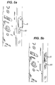
Figures 5a and 5b are perspective views of part of the mechanism shown inFigure 1 in two different positions; -
Figures 6a and 6b are detailed views of an alternative snib mechanism; and -
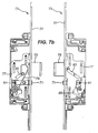
Figures 7a and7b are side views of an automatic latch/bolt mechanism in a door open and a door closed arrangement respectively. - With reference to the drawings, a
locking mechanism 1 includes agearbox 3 housing alatch 5 and adeadbolt 7 and carrying adrive bar 9. Thegearbox 3 is also adapted to receive a handle in asquare drive 11 and a "Eurocylinder" lock (not shown) in anaperture 13. - Turning now to
figure 2 , thelatch 5 is biased outwardly by acoil spring 15. Retraction of thelatch 5 can be achieved by rotation oflatch lever 17a aboutpivot 19a abutting alatch screw 21a fixed in thelatch 5. Thelatch lever 17a is driven by acam surface 23a on thesquare drive 11a. - A similar combination of
latch lever 17b,pivot 19b, latch screw 21b,cam surface 23b andsquare drive 11b can be found on the opposite side of thelatch 5, as shown infigure 3 . If the latching mechanism were mounted in a door (not shown) of a room,figure 2 shows the view from outside the room andfigure 3 shows the view of the mechanism from inside the room. - As will be appreciated, if the
latch screw 21 a is removed from thelatch 5, thelatch lever 17a will have nothing to act upon so will not be able to withdraw thelatch 5 during operation of thesquare drive 11 a. Thus, thelatch 5 cannot be withdrawn from outside of the room (or dwelling), thereby providing a degree of security. Similarly, if the latch screw 21 b were to be removed from thelatch 5, thelatch lever 17b would have nothing to bear against and it would not be possible to use thesquare drive 11 b on the inside of the door to withdraw thelatch 5. Some other unlocking mechanism would be needed. -
Mechanism 1 also includes adeadbolt 7 which is mounted for sliding engagement in thegearbox 3 through anaperture 29 in aface plate 31. The deadbolt includes aslidable detent 33 which travels in a cut-out 27 (cf.figure 1 ) between locked and unlocked positions. The locking and unlocking of thedeadbolt 7 is achieved by means of thecylinder lock 45 shown infigure 4 . - A portion of the
drive bar 9 is situated within thegearbox 3. Thedrive bar 9 has a small cut-out 35 for receiving aflange 37 extending from thelatch 5. Thedrive bar 9 also includes a larger cut-out 39 for receiving a block 41 formed on the side of thedeadbolt 7. Thus, when theflange 37 of thelatch 5 is situated within the cut-out 35 of thedrive bar 9, thedrive bar 9 is unable to move to activate second and third latching/bolting devices/modules spaced from thegearbox 3. Similarly, if the block 41 on the dead bolt is situated within the cut-out 39 in thedrive bar 9, this too prevents movement of thedrive bar 9. Hence, it is necessary to remove both theflange 37 and the block 41 from thedrive bar 9 before thedrive bar 9 can be driven. - To enable the two
square drives 11 to be controlled separately, separate handles are applied to each side of the locking mechanism with short square shafts which engage only their respective square drives. Aplastic sheet 43 situated between the square drives 11 prevents one handle from having any chance of accidentally operating the other square drive. Thus, improved safety and security is thereby provided. - Turning now to
figure 4 , thelocking mechanism 1 is viewed from the "inside". Due to the external latch screw 21 b having been removed, rotation of the outside handle (not shown) will rotate thesquare drive 11 b and thelatch lever 17b, but this will not result in withdrawal of thelatch 5. If thelatch 5 is not withdrawn, thedrive bar 9 cannot be moved to unlock any related latches or bolts. Thus, the door is secure. - However, if a user has a key and can operate the
cylinder lock 45, the door can be opened. In particular, upon the first rotation of a key (not shown) in thecylinder lock 45, thedeadbolt 7 is withdrawn as shown inFigure 4b and links of a latch/cylinder drive bar 47 are aligned. Upon a second rotation of the key in thecylinder lock 45, acam 49 of thecylinder lock 45 drives the latch/cylinder drive bar 47 upwards such that alatch lever 51 drives thelatch 5 inwards. A latch/cylinder drive retaining pin (not shown) is forced into a sprung clip, thereby preventing the latch/cylinder drive bar 47 from moving. Thelatch 5 is thereby also held retracted. The key can then be rotated and removed, without releasing thelatch 5. Rotation of the handle (not shown) in thesquare drive 11 b will then act on a square drive pressing 55, which will subsequently act on thedrive bar 9, to drive thebar 9 to release latches or bolts of related modules. As this occurs, thedrive bar 9 drives the retaining pin out of the sprung clip, thereby releasing the latch/cylinder drive bar 47 andlatch 5. - When the handle is released, the
square drive 11 b returns to its rest position and thelatch 5 is released. When closed, the door will then latch and be secure from intruders. If the handle is driven upwards, the locking modules will engage in the frame keeps and theflange 37 on thelatch 5 will engage with thedrive bar 9, further securing the door. - As should be appreciated, as a handle is rotated to rotate a
square drive 11, an initial rotation of 28 degrees results in theflange 37 disengaging from thedrive bar 9, so that the square drive pressing 55 can act on thedrive bar 9 to drive thedrive bar 9. Thus, by the time the latch is fully retracted,drive bar 9 has moved sufficiently to fully disengage any top and bottom locking points. Thus, a door can be opened freely. - To summarise, the proposed locking mechanism can be adjusted prior to fitting to prevent "follow-on crime". To prevent "follow-on crime", a fitter of the mechanism must disengage the latch screw 21 b (or 21 a dependent on whether the door is left or right handed) from the outside of the
latch 5 prior to fitting the locking mechanism. Then, when the lock has been fitted, the following operation is required to gain access the dwelling: - 1. The homeowner returns to the dwelling.
- 2. The homeowner unlocks the
deadbolt 7 using the key. - 3. The homeowner continues to rotate the key to retract the
latch 5. - 4. The home owner can rotate the key back and remove the key (whilst the latch is held in its retracted position).
- 5. The homeowner pushes down on the handle (- the handle will operate as the latch is already retracted).
- 6. The module locking points will retract and the latch will be released.
- 7. The homeowner can enter the dwelling and close the door behind them.
- 8. The
latch 5 will then engage with the frame keep (not shown), and the door cannot be opened from the outside via the handle because it cannot drive thelatch 5. - 9. Driving the handle up will throw the locking point bolts and further secure the door. These modular locking points can also not be driven by the outside handle until the latch is retracted.
- 10. The homeowner can turn the key to deadbolt the door.
- When the homeowner is ready to exit, the homeowner simply turns the key to retract the
dead bolt 7 and drives the inside handle down to operate thelatch 5 and all other locking points. Thelocking mechanism 1 is set to avoid "follow-on crime" by having the external latch screw 21 b removed. - A
face plate snib 61 is provided, as shown infigure 5 .Snib 61 is a simple slider in theface plate 31 which can be moved to retain thelatch 5 retracted as a user exits though the door and wishes to be able to reopen the door from the outside. Once thesnib 61 has been activated, thelatch 5 is held retracted, so both the internal and external handles of the door can be used to drivebar 9 to release the various locking points without any fear of thelatch 5 re-engaging with the lockingbar 9 and preventing access from outside. This is useful when a user wishes to leave the dwelling without the key. However, the door cannot be secured/locked when thesnib 61 is in operation. - As an alternative to the
face plate snib 61, ahandle snib 63 may be used.
In this case, thesnib 63 is situated within thegearbox 3 and is driven by a lever (not shown) accessible from outside the gearbox casing. Upon rotation of thesnib 63 from its inactive position shown infigure 6a to its active position shown infigure 6b , thelatch 5 can be held retracted. The inactive and active positions are defined by a sprungsteel clip 65 engaging in therecesses snib 63. - Conventional multi-point locks are not always fully secure. Modules on a conventional multi-point locking system are engaged by the user driving a door handle upward. Thus, if the user forgets to drive the handle upwards, the door will only be secured via its
latch 5. The present invention therefore includes the concept of an automatic multi-point lock system (shown infigure 7 ) using auto-bolt modules, which automatically engage when the door is closed, requiring no input from the user. Thus, when the door is closed, the locking system is secured at the latch and top and bottom locking modules without the requirement for any user input. The key can also then be turned to deadlock the lock. - The auto-bolt operation is achieved by virtue of individual actuators associated with each latch or bolt. When the door is closed, the
actuator 71 which extends from theface plate 31 of themodule 73 is forced inwards, and this releases a sprung-loadedbolt 75. For smooth running, thelatch 5 and the top andbottom locking actuators 71 must be depressed simultaneously to fire thebolts 75, thereby preventing misfires or problems associated with a door which is open with a bolt or latch 75 already extended. - Each
remote bolt module 73 includes a portion ofdrive bar 77 for controlling the motion of itsbolt 75, abolt spring 79 for urging thebolt 75 outwards, and anactuator 71 and associatedspring 81. Themodule drive bar 77 includes aninclined slot 83, which carries astud 84 integral with thebolt 75, and acutout 85 for receiving a portion of theactuator 71. When theactuator 71 is triggered, it is pushed out of thecutout 85 and allows thedrive bar 77 to move. As a result, the spring-biasedbolt 75 is guided by theslot 83 into its exposed active position. To reset themodule 73, thedrive bar 77 is driven by rotation of a handle acting on themain gearbox 3 to withdraw thebolt 75. As a result, the actuator is once again urged into thecutout 85 and thereby prevents further movement of thedrive bar 77 until such time as the actuator is again triggered. - It will of course be understood that the present invention has been described above purely by way of example, and that modifications of detail can be made within the scope of the present invention.
Claims (15)
- A mechanism for latching a vent, comprising drive means, a spring biased latch and a drive bar, wherein the drive bar cannot be driven by the drive means until the latch is withdrawn.
- A mechanism as claimed in claim 1, wherein the latch engages the drive bar to prevent motion of the drive bar.
- A mechanism as claimed in claim 1 or claim 2, wherein the latch is withdrawn by the drive means.
- A mechanism as claimed in any preceding claim, wherein the drive bar controls at least one further locking mechanism.
- A mechanism as claimed in any preceding claim, wherein a locking means controls motion of the latch.
- A mechanism as claimed in any preceding claim, wherein a deadbolt engages the drive bar to lock the mechanism.
- A mechanism as claimed in claim 6, wherein the deadbolt is controlled by a locking means.
- A mechanism as claimed in claim 5 or claim 7, wherein the locking means is key operated.
- A mechanism as claimed in any preceding claim, wherein the drive means include a handle.
- A method of entering and securing a door, comprising the steps of(i) unlocking a door with a key;(ii) opening the door;(iii) closing the door; and(iv) moving a handle to drive one or more bolts such that the bolts cannot be retracted from outside the door without the use of a key.
- A mechanism for latching a vent, comprising a latch, a drive means and a locking device, wherein when the locking device is deactivated, the latch is held retracted, thereby allowing the drive means to open the vent.
- A mechanism for latching a vent, comprising opposing drive means provided on opposite sides of the mechanism, wherein the drive means function independently.
- A mechanism as claimed in claim 12, wherein the drive means are separated by a plate.
- A mechanism as claimed in claim 13, wherein the plate is a plastics plate.
- A mechanism for locking a vent, comprising a plurality of locking points, a drive bar acting between the locking points and a plurality of triggers which, when activated, cause the locking points to lock.
Applications Claiming Priority (1)
| Application Number | Priority Date | Filing Date | Title |
|---|---|---|---|
| GB0900636A GB2466962A (en) | 2009-01-15 | 2009-01-15 | A locking mechanism with various control arrangements |
Publications (1)
| Publication Number | Publication Date |
|---|---|
| EP2208840A2 true EP2208840A2 (en) | 2010-07-21 |
Family
ID=40433354
Family Applications (1)
| Application Number | Title | Priority Date | Filing Date |
|---|---|---|---|
| EP10250007A Withdrawn EP2208840A2 (en) | 2009-01-15 | 2010-01-06 | A locking mechanism |
Country Status (3)
| Country | Link |
|---|---|
| EP (1) | EP2208840A2 (en) |
| CN (1) | CN202047652U (en) |
| GB (1) | GB2466962A (en) |
Cited By (3)
| Publication number | Priority date | Publication date | Assignee | Title |
|---|---|---|---|---|
| EP2754795A3 (en) * | 2013-01-11 | 2015-07-29 | Wilh. Schlechtendahl & Söhne GmbH & Co. KG | Strike box or mortise lock |
| WO2015144357A1 (en) * | 2014-03-24 | 2015-10-01 | Kfv Karl Fliether Gmbh & Co. Kg | Method for operating a panic lock |
| US11933092B2 (en) | 2019-08-13 | 2024-03-19 | SimpliSafe, Inc. | Mounting assembly for door lock |
Families Citing this family (13)
| Publication number | Priority date | Publication date | Assignee | Title |
|---|---|---|---|---|
| DE202011102905U1 (en) * | 2011-07-06 | 2012-10-11 | Maco Technologie Gmbh | lock |
| US9637957B2 (en) * | 2012-11-06 | 2017-05-02 | Amesbury Group, Inc. | Automatically-extending remote door lock bolts |
| ITTO20130142A1 (en) * | 2013-02-21 | 2014-08-22 | Savio Spa | AUXILIARY SAFETY MODULE FOR DOORS EQUIPPED WITH AN ANTI-PANIC OPENING DEVICE |
| EP2821569A1 (en) * | 2013-07-04 | 2015-01-07 | Timothy Christopher Finn | Strike plate and lock |
| US10968661B2 (en) | 2016-08-17 | 2021-04-06 | Amesbury Group, Inc. | Locking system having an electronic deadbolt |
| GB2560957A (en) * | 2017-03-30 | 2018-10-03 | Ingenious Locks & Hardware Ltd | A drive assembly for a locking device of a door or window |
| CA3059779A1 (en) | 2017-04-18 | 2018-10-25 | Amesbury Group, Inc. | Modular electronic deadbolt systems |
| US10808424B2 (en) | 2017-05-01 | 2020-10-20 | Amesbury Group, Inc. | Modular multi-point lock |
| US11066850B2 (en) | 2017-07-25 | 2021-07-20 | Amesbury Group, Inc | Access handle for sliding doors |
| CA3036398A1 (en) | 2018-03-12 | 2019-09-12 | Amesbury Group, Inc. | Electronic deadbolt systems |
| CN108843151A (en) * | 2018-08-16 | 2018-11-20 | 广东合和建筑五金制品有限公司 | A kind of linkage lock body structure |
| US11834866B2 (en) | 2018-11-06 | 2023-12-05 | Amesbury Group, Inc. | Flexible coupling for electronic deadbolt systems |
| US11661771B2 (en) | 2018-11-13 | 2023-05-30 | Amesbury Group, Inc. | Electronic drive for door locks |
Family Cites Families (17)
| Publication number | Priority date | Publication date | Assignee | Title |
|---|---|---|---|---|
| IL66249A (en) * | 1982-07-07 | 1985-12-31 | Rochman Zvi Henri | Safety lock with automatic bolting |
| DE8909119U1 (en) * | 1989-07-27 | 1989-09-28 | Bks Gmbh, 5620 Velbert, De | |
| ES2014852A6 (en) * | 1989-08-08 | 1990-07-16 | Lloses Ballester Celestino | Closure for doors and windows |
| US5290077A (en) * | 1992-01-14 | 1994-03-01 | W&F Manufacturing, Inc. | Multipoint door lock assembly |
| US5603534A (en) * | 1992-10-30 | 1997-02-18 | Fuller; Mark W. | Lock mechanism |
| DE9321038U1 (en) * | 1993-10-15 | 1995-11-02 | Krachten Theodor | Self-locking security door lock |
| DE4337969A1 (en) * | 1993-10-15 | 1995-04-20 | Theodor Krachten | Self-locking safety door lock |
| US5852944A (en) * | 1997-04-18 | 1998-12-29 | Stephen C. Cohen | Remotely controlled door lock |
| JP3088342B2 (en) * | 1997-06-16 | 2000-09-18 | タキゲン製造株式会社 | Clemonrock device |
| DE19826869C1 (en) * | 1998-06-17 | 2000-01-13 | Steinbach & Vollmann | Lock for security door |
| DE19842279A1 (en) * | 1998-09-16 | 2000-03-23 | Fuhr Carl Gmbh & Co | Lock, especially espagnolette lock with adjustable latch actuation |
| US6257030B1 (en) * | 1999-06-09 | 2001-07-10 | Therma-Tru Corporation | Thumb-operated multilatch door lock |
| GB2364545B (en) * | 2000-07-07 | 2003-11-12 | Era Products Ltd | Locks |
| JP4198382B2 (en) * | 2002-04-22 | 2008-12-17 | 美和ロック株式会社 | Gremon tablets |
| DE102004002270A1 (en) * | 2004-01-16 | 2005-08-04 | Aug. Winkhaus Gmbh & Co. Kg | Espagnolette |
| NL1029754C2 (en) * | 2005-08-17 | 2007-03-05 | Lips Nederland B V | Locker with shared tumbler. |
| GB2444730B (en) * | 2006-12-15 | 2012-01-25 | Securistyle Ltd | A lock |
-
2009
- 2009-01-15 GB GB0900636A patent/GB2466962A/en not_active Withdrawn
-
2010
- 2010-01-06 EP EP10250007A patent/EP2208840A2/en not_active Withdrawn
- 2010-01-13 CN CN2010200036091U patent/CN202047652U/en not_active Expired - Fee Related
Non-Patent Citations (1)
| Title |
|---|
| None |
Cited By (5)
| Publication number | Priority date | Publication date | Assignee | Title |
|---|---|---|---|---|
| EP2754795A3 (en) * | 2013-01-11 | 2015-07-29 | Wilh. Schlechtendahl & Söhne GmbH & Co. KG | Strike box or mortise lock |
| WO2015144357A1 (en) * | 2014-03-24 | 2015-10-01 | Kfv Karl Fliether Gmbh & Co. Kg | Method for operating a panic lock |
| CN106661901A (en) * | 2014-03-24 | 2017-05-10 | Kfv卡尔弗利特有限及两合公司 | Method for operating a panic lock |
| CN106661901B (en) * | 2014-03-24 | 2019-09-17 | Kfv卡尔弗利特有限及两合公司 | Method for running emergency lock |
| US11933092B2 (en) | 2019-08-13 | 2024-03-19 | SimpliSafe, Inc. | Mounting assembly for door lock |
Also Published As
| Publication number | Publication date |
|---|---|
| GB0900636D0 (en) | 2009-02-25 |
| CN202047652U (en) | 2011-11-23 |
| GB2466962A (en) | 2010-07-21 |
Similar Documents
| Publication | Publication Date | Title |
|---|---|---|
| EP2208840A2 (en) | A locking mechanism | |
| JP5069680B2 (en) | Security system for entrance barrier | |
| US7878034B2 (en) | Locking arrangement for a hinged panel | |
| US7634928B2 (en) | Door locking system | |
| US7025394B1 (en) | Lock system for integrating into an entry door having a vertical expanse and providing simultaneous multi-point locking along the vertical expanse of the entry door | |
| US8056941B2 (en) | Lock with emergency unlocking mechanism | |
| US20230323705A1 (en) | Locking assembly with spring mechanism | |
| WO2013016068A1 (en) | Multi-point lock having sequentially-actuated locking elements | |
| US20120137742A1 (en) | Locking Device and Associated Methods | |
| US20180371792A1 (en) | Door lock mortise | |
| CN113167081B (en) | Lock assembly | |
| US20190277064A1 (en) | Automatic locking-deadbolt assembly in a door | |
| US11851913B2 (en) | Hook bolt for door lock | |
| EP2148029A1 (en) | Automatic lock | |
| US9091103B2 (en) | Sliding glass door safety latch | |
| WO2011109573A2 (en) | Mortise lock with selectable functions | |
| AU2010226865A1 (en) | Escape Lock | |
| US20190226251A1 (en) | Locking Device to Secure a Door and Methods of Installing and Operating the Locking Device | |
| US20200240176A1 (en) | Locking Device to Secure a Door and Methods for Installing and Operating the Locking Device | |
| US9206629B1 (en) | Gate securing device fully controllable from each gate side and method therefor | |
| EP3461976B1 (en) | Improved door locking mechanism | |
| KR200473054Y1 (en) | Improved locking device for door | |
| EP4144943A1 (en) | Dual lock actuator | |
| GB2408773A (en) | Lock actuation mechanism comprising spring-loaded locking pin | |
| JP2003307067A (en) | Bolt for child door, interlocked with lock retainer |
Legal Events
| Date | Code | Title | Description |
|---|---|---|---|
| PUAI | Public reference made under article 153(3) epc to a published international application that has entered the european phase |
Free format text: ORIGINAL CODE: 0009012 |
|
| AK | Designated contracting states |
Kind code of ref document: A2 Designated state(s): AT BE BG CH CY CZ DE DK EE ES FI FR GB GR HR HU IE IS IT LI LT LU LV MC MK MT NL NO PL PT RO SE SI SK SM TR |
|
| AX | Request for extension of the european patent |
Extension state: AL BA RS |
|
| RAP1 | Party data changed (applicant data changed or rights of an application transferred) |
Owner name: ASSA ABLOY LIMITED |
|
| RIC1 | Information provided on ipc code assigned before grant |
Ipc: E05B 63/16 20060101ALI20160121BHEP Ipc: E05B 63/20 20060101ALI20160121BHEP Ipc: E05C 9/18 20060101ALN20160121BHEP Ipc: E05B 63/00 20060101ALI20160121BHEP Ipc: E05C 9/00 20060101AFI20160121BHEP |
|
| RIC1 | Information provided on ipc code assigned before grant |
Ipc: E05B 63/16 20060101ALI20160512BHEP Ipc: E05C 9/18 20060101ALN20160512BHEP Ipc: E05B 63/00 20060101ALI20160512BHEP Ipc: E05B 63/20 20060101ALI20160512BHEP Ipc: E05C 9/00 20060101AFI20160512BHEP |
|
| STAA | Information on the status of an ep patent application or granted ep patent |
Free format text: STATUS: THE APPLICATION IS DEEMED TO BE WITHDRAWN |
|
| 18D | Application deemed to be withdrawn |
Effective date: 20160802 |