EP2208470B1 - Patellaresektionsführung - Google Patents
Patellaresektionsführung Download PDFInfo
- Publication number
- EP2208470B1 EP2208470B1 EP10150487A EP10150487A EP2208470B1 EP 2208470 B1 EP2208470 B1 EP 2208470B1 EP 10150487 A EP10150487 A EP 10150487A EP 10150487 A EP10150487 A EP 10150487A EP 2208470 B1 EP2208470 B1 EP 2208470B1
- Authority
- EP
- European Patent Office
- Prior art keywords
- patella
- guide
- patient
- resectioning
- cutting
- Prior art date
- Legal status (The legal status is an assumption and is not a legal conclusion. Google has not performed a legal analysis and makes no representation as to the accuracy of the status listed.)
- Active
Links
- 210000004417 patella Anatomy 0.000 title claims abstract description 148
- 238000005520 cutting process Methods 0.000 claims abstract description 95
- 238000007373 indentation Methods 0.000 claims description 18
- 239000000463 material Substances 0.000 claims description 10
- 239000006261 foam material Substances 0.000 abstract description 2
- 238000000034 method Methods 0.000 description 35
- 210000003484 anatomy Anatomy 0.000 description 19
- 210000000988 bone and bone Anatomy 0.000 description 9
- 210000003127 knee Anatomy 0.000 description 6
- 238000001356 surgical procedure Methods 0.000 description 6
- 210000002435 tendon Anatomy 0.000 description 6
- 210000000689 upper leg Anatomy 0.000 description 5
- 239000007943 implant Substances 0.000 description 4
- 239000007769 metal material Substances 0.000 description 4
- 238000002591 computed tomography Methods 0.000 description 2
- 238000010586 diagram Methods 0.000 description 2
- 210000003811 finger Anatomy 0.000 description 2
- 238000003384 imaging method Methods 0.000 description 2
- 238000002513 implantation Methods 0.000 description 2
- 238000004519 manufacturing process Methods 0.000 description 2
- -1 polyethylene Polymers 0.000 description 2
- 238000012552 review Methods 0.000 description 2
- 210000003813 thumb Anatomy 0.000 description 2
- 229910000684 Cobalt-chrome Inorganic materials 0.000 description 1
- 239000004698 Polyethylene Substances 0.000 description 1
- 239000004743 Polypropylene Substances 0.000 description 1
- 229910000831 Steel Inorganic materials 0.000 description 1
- RTAQQCXQSZGOHL-UHFFFAOYSA-N Titanium Chemical compound [Ti] RTAQQCXQSZGOHL-UHFFFAOYSA-N 0.000 description 1
- WAIPAZQMEIHHTJ-UHFFFAOYSA-N [Cr].[Co] Chemical compound [Cr].[Co] WAIPAZQMEIHHTJ-UHFFFAOYSA-N 0.000 description 1
- 238000011882 arthroplasty Methods 0.000 description 1
- 210000000845 cartilage Anatomy 0.000 description 1
- 239000010952 cobalt-chrome Substances 0.000 description 1
- 238000011960 computer-aided design Methods 0.000 description 1
- 239000003814 drug Substances 0.000 description 1
- 229940079593 drug Drugs 0.000 description 1
- 238000003708 edge detection Methods 0.000 description 1
- 210000005224 forefinger Anatomy 0.000 description 1
- 210000000629 knee joint Anatomy 0.000 description 1
- 238000002595 magnetic resonance imaging Methods 0.000 description 1
- 238000003801 milling Methods 0.000 description 1
- 239000004033 plastic Substances 0.000 description 1
- 229920003023 plastic Polymers 0.000 description 1
- 229920000573 polyethylene Polymers 0.000 description 1
- 229920000642 polymer Polymers 0.000 description 1
- 229920001155 polypropylene Polymers 0.000 description 1
- 238000012545 processing Methods 0.000 description 1
- 238000009877 rendering Methods 0.000 description 1
- 238000004513 sizing Methods 0.000 description 1
- 239000010959 steel Substances 0.000 description 1
- 210000001519 tissue Anatomy 0.000 description 1
- 239000010936 titanium Substances 0.000 description 1
- 229910052719 titanium Inorganic materials 0.000 description 1
- 238000010200 validation analysis Methods 0.000 description 1
Images


Classifications
-
- A—HUMAN NECESSITIES
- A61—MEDICAL OR VETERINARY SCIENCE; HYGIENE
- A61B—DIAGNOSIS; SURGERY; IDENTIFICATION
- A61B17/00—Surgical instruments, devices or methods, e.g. tourniquets
- A61B17/14—Surgical saws ; Accessories therefor
- A61B17/15—Guides therefor
- A61B17/154—Guides therefor for preparing bone for knee prosthesis
- A61B17/158—Cutting patella
-
- A—HUMAN NECESSITIES
- A61—MEDICAL OR VETERINARY SCIENCE; HYGIENE
- A61B—DIAGNOSIS; SURGERY; IDENTIFICATION
- A61B90/00—Instruments, implements or accessories specially adapted for surgery or diagnosis and not covered by any of the groups A61B1/00 - A61B50/00, e.g. for luxation treatment or for protecting wound edges
- A61B90/10—Instruments, implements or accessories specially adapted for surgery or diagnosis and not covered by any of the groups A61B1/00 - A61B50/00, e.g. for luxation treatment or for protecting wound edges for stereotaxic surgery, e.g. frame-based stereotaxis
- A61B90/11—Instruments, implements or accessories specially adapted for surgery or diagnosis and not covered by any of the groups A61B1/00 - A61B50/00, e.g. for luxation treatment or for protecting wound edges for stereotaxic surgery, e.g. frame-based stereotaxis with guides for needles or instruments, e.g. arcuate slides or ball joints
-
- A—HUMAN NECESSITIES
- A61—MEDICAL OR VETERINARY SCIENCE; HYGIENE
- A61B—DIAGNOSIS; SURGERY; IDENTIFICATION
- A61B34/00—Computer-aided surgery; Manipulators or robots specially adapted for use in surgery
- A61B34/10—Computer-aided planning, simulation or modelling of surgical operations
- A61B2034/108—Computer aided selection or customisation of medical implants or cutting guides
-
- A—HUMAN NECESSITIES
- A61—MEDICAL OR VETERINARY SCIENCE; HYGIENE
- A61F—FILTERS IMPLANTABLE INTO BLOOD VESSELS; PROSTHESES; DEVICES PROVIDING PATENCY TO, OR PREVENTING COLLAPSING OF, TUBULAR STRUCTURES OF THE BODY, e.g. STENTS; ORTHOPAEDIC, NURSING OR CONTRACEPTIVE DEVICES; FOMENTATION; TREATMENT OR PROTECTION OF EYES OR EARS; BANDAGES, DRESSINGS OR ABSORBENT PADS; FIRST-AID KITS
- A61F2250/00—Special features of prostheses classified in groups A61F2/00 - A61F2/26 or A61F2/82 or A61F9/00 or A61F11/00 or subgroups thereof
- A61F2250/0014—Special features of prostheses classified in groups A61F2/00 - A61F2/26 or A61F2/82 or A61F9/00 or A61F11/00 or subgroups thereof having different values of a given property or geometrical feature, e.g. mechanical property or material property, at different locations within the same prosthesis
- A61F2250/0018—Special features of prostheses classified in groups A61F2/00 - A61F2/26 or A61F2/82 or A61F9/00 or A61F11/00 or subgroups thereof having different values of a given property or geometrical feature, e.g. mechanical property or material property, at different locations within the same prosthesis differing in elasticity, stiffness or compressibility
-
- A—HUMAN NECESSITIES
- A61—MEDICAL OR VETERINARY SCIENCE; HYGIENE
- A61F—FILTERS IMPLANTABLE INTO BLOOD VESSELS; PROSTHESES; DEVICES PROVIDING PATENCY TO, OR PREVENTING COLLAPSING OF, TUBULAR STRUCTURES OF THE BODY, e.g. STENTS; ORTHOPAEDIC, NURSING OR CONTRACEPTIVE DEVICES; FOMENTATION; TREATMENT OR PROTECTION OF EYES OR EARS; BANDAGES, DRESSINGS OR ABSORBENT PADS; FIRST-AID KITS
- A61F2250/00—Special features of prostheses classified in groups A61F2/00 - A61F2/26 or A61F2/82 or A61F9/00 or A61F11/00 or subgroups thereof
- A61F2250/0014—Special features of prostheses classified in groups A61F2/00 - A61F2/26 or A61F2/82 or A61F9/00 or A61F11/00 or subgroups thereof having different values of a given property or geometrical feature, e.g. mechanical property or material property, at different locations within the same prosthesis
- A61F2250/0019—Special features of prostheses classified in groups A61F2/00 - A61F2/26 or A61F2/82 or A61F9/00 or A61F11/00 or subgroups thereof having different values of a given property or geometrical feature, e.g. mechanical property or material property, at different locations within the same prosthesis differing in hardness, e.g. Vickers, Shore, Brinell
Definitions
- This invention relates to orthopaedic surgical instruments, especially to a patella resectioning guide.
- Joint arthroplasty is a well-known surgical procedure by which a diseased and/or damaged natural joint is replaced by a prosthetic joint.
- a typical knee prosthesis includes a tibial tray, a femoral component, and a polymer insert or bearing positioned between the tibial tray and the femoral component.
- the knee prosthesis may also include a prosthetic patella component, which is secured to a posterior side of the patient's surgically-prepared patella. To do so, an orthopaedic surgeon may resect the posterior side of the patient's natural patella to secure the prosthetic component thereto.
- the patella component articulates with the patient's natural or prosthetic femur during extension and flexion of the patient's knee.
- orthopaedic surgeons use a variety of orthopaedic surgical instruments such as, for example, cutting blocks, drill guides, milling guides, and other surgical instruments.
- orthopaedic surgical instruments are generic with respect to the patient such that the same orthopaedic surgical instrument may be used on a number of different patients during similar orthopaedic surgical procedures.
- US-A-2005/0234461 discloses instruments for use in resecting a patella which include a cutting block and a clamp.
- the cutting block can have a groove in its opposite face which are designed to mate with a patellar clamp.
- the groove is shaped to receive a ring-shaped grasper on the clamp.
- the present invention provides a patella resectioning guide assembly as defined in claim 1.
- the cutting guide may be formed from a material different from the material forming the body.
- the cutting guide may be formed from a metallic material or a non-metallic material.
- the body may be formed from a polymeric material. In such embodiments, the cutting guide may be over-moulded with the body.
- the resectioning guide may further include a medial side corresponding to the medial side of the patient's patella when patella is received in the negative contour of the body. Additionally, the resectioning guide may include a lateral side corresponding to the lateral side of the patient's patella when the patella is received in the negative contour of the body.
- the cutting slot of the cutting guide may include a first opening on the medial side of the resectioning guide. The first opening may be sized to receive a cutting saw blade.
- the cutting slot of the cutting guide may include a second opening on the lateral side of the resectioning guide. The second opening may also be sized to receive a cutting saw blade.
- the resectioning guide may include an indentation formed on the medial side of the resectioning guide. The indentation may extend from the outer surface of the body to the cutting slot of the cutting guide.
- the body of the resectioning guide may include a sidewall extending upwardly from the bone-facing surface and intersecting with the resectioning plane to prevent the cutting saw blade from extending beyond the body.
- the sidewall may be positioned on the lateral side of the resectioning guide in some embodiments.
- the cutting guide may be positioned on the medial side of the resectioning guide such that the negative contour of the body may be positioned between the cutting guide and the sidewall.
- the indentation may be sized to receive a thumb of a surgeon such that the body and patella may be held between the thumb and forefinger of the orthopaedic surgeon.
- the resectioning guide may further include compressible foam material secured to the outer surface of the body.
- the resectioning guide may further include an enclosed housing extending upwardly from the bone-facing surface of the body.
- the enclosed housing may be spaced apart from the cutting guide.
- the enclosed housing may have an aperture co-planar with the resectioning plane defined by the cutting slot.
- the enclosed housing may be positioned on the medial side of the resectioning guide, and the cutting guide may be positioned on the lateral side of the resectioning guide such that the negative contour is formed between the cutting guide and the enclosed housing.
- the resectioning guide includes an enclosed housing spaced apart from the cutting guide and extending upwardly from the bone-facing surface of the body, the enclosed housing having an aperture co-planar with the resectioning plane defined by the cutting slot.
- the enclosed housing is positioned on the medial side of the resectioning guide, and the cutting guide is positioned on the lateral side of the resectioning guide such that the negative contour is formed between the cutting guide and the enclosed housing.
- anatomical references such as anterior, posterior, medial, lateral, superior, inferior, etcetera
- terms representing anatomical references may be used throughout the specification in reference to the orthopaedic implants and surgical instruments described herein as well as in reference to the patient's natural anatomy.
- Such terms have well-understood meanings in both the study of anatomy and the field of orthopaedics. Use of such anatomical reference terms in the written description and claims is intended to be consistent with their well-understood meanings unless noted otherwise.
- FIG. 1 is a flow diagram with details of a method 10 which can be used to fabricate a customised patient-specific orthopaedic surgical instrument.
- customised patient-specific orthopaedic surgical instrument is used in this document to refer to a surgical tool for use by a surgeon in performing an orthopaedic surgical procedure that is intended, and configured, for use on a particular patient.
- a "customised patient-specific orthopaedic surgical instrument” is distinct from a standard, non-patient specific orthopaedic surgical instrument which is intended for use on a variety of different patients.
- customised patient-specific orthopaedic surgical instrument is distinct from orthopaedic prostheses, whether patient-specific or generic, which are surgically implanted in the body of the patient. Rather, customised patient-specific orthopaedic surgical instruments are used by an orthopaedic surgeon to assist in the implantation of orthopaedic prostheses.
- the customised patient-specific orthopaedic surgical instrument may be customised to the particular patient based on the location at which the instrument is to be coupled to one or more bones of the patient.
- the customised patient-specific orthopaedic instrument may be a customised patient-specifc patella resectioning guide including one or more bone-contacting or facing surfaces having a negative contour that matches the contour of a portion of the patient's patella, which is discussed in more detail below with reference to FIGS. 2 to 7 .
- the customised patient-specific patella resectioning guide is configured to be coupled to the patient's patella at a unique location and position with respect to the patient's bony anatomy.
- the negative contours of the bone-contacting surfaces are configured to receive a matching contour surface of the portion of the patient's patella (and, in some cases, femur).
- the orthopaedic surgeon's guesswork and/or intra-operative decision-making with respect to the placement of the patient-specific patella resectioning guide are reduced.
- the orthopaedic surgeon may simply couple the customised patient-specific patella resectioning guide to the patient's patella. When so coupled, the customised patient-specific patella resectioning guide defines the thickness of bone the surgeon will resect from the posterior side of the patient's patella.
- the method 10 includes process steps 12, 14 in which an orthopaedic surgeon performs pre-operative planning of the patella resectioning procedure to be performed on a patient.
- the process steps 12, 14 may be performed in any order or contemporaneously with each other.
- a number of medical images of the patient's patella and the surrounding bony anatomy are generated.
- the orthopaedic surgeon or other healthcare provider may operate an imaging system to generate the medical images.
- the medical images may be embodied as any number and type of medical images capable of being used to generate a three-dimensional rendered model of the patient's patella and surrounding bony anatomy.
- the medical images may be embodied as any number of computed tomography (CT) images, magnetic resonance imaging (MRI) images, or other three-dimensional medical images.
- CT computed tomography
- MRI magnetic resonance imaging
- the medical images may be embodied as a number of X-ray images or other two-dimensional images from which a three-dimensional rendered model of the patient's patella and the surrounding bony anatomy may be generated.
- the orthopaedic surgeon may determine any additional pre-operative constraint data.
- the constraint data may be based on the orthopaedic surgeon's preferences, preferences of the patient, anatomical aspects of the patient, guidelines established by the healthcare facility, or the like.
- the constraint data may include the orthopaedic surgeon's preference for a particular prosthesis type, the thickness of the bone to resect, the size range of the orthopaedic implant, and/or the like.
- the orthopaedic surgeon's preferences are saved as a surgeon's profile, which may be used as a default constraint values for further surgical plans.
- the medical images and the constraint data are transmitted or otherwise provided to an orthopaedic surgical instrument vendor or manufacturer.
- the medical images and the constraint data may be transmitted to the vendor via electronic means such as a network or the like.
- the vendor processes the images in step 18.
- the orthopaedic surgical instrument vendor or manufacturer process the medical images to facilitate the determination of the proper positioning of the prosthetic component, implant sizing, and fabrication of the customised patient-specific patella resectioning guide as discussed in more detail below.
- the vendor may convert or otherwise generate three-dimensional images from the medical images.
- the vendor may use a suitable computer algorithm to generate one or more three-dimensional images from the number of two-dimensional images.
- the medical images may be generated based on an established standard such as the Digital Imaging and Communications in Medicine (DICOM) standard.
- DICOM Digital Imaging and Communications in Medicine
- an edge-detection, thresholding, watershed, or shape-matching algorithm may be used to convert or reconstruct images to a format acceptable in a computer aided design application or other image processing application.
- an algorithm may be used to account for tissue such as cartilage not discernable in the generated medical images.
- any three-dimensional model of the patient-specific instrument may be modified according to such algorithm to increase the fit and function of the instrument.
- the vendor may process the medical images, and/or the converted/reconstructed images from process step 20, to determine a number of aspects related to the bony anatomy of the patient such as the anatomical axis of the patient's bones, the mechanical axis of the patient's bone, other axes and various landmarks, and/or other aspects of the patient's bony anatomy.
- the vendor may use any suitable algorithm to process the images.
- the resectioning plane of the patient's patella is determined in process step 24.
- the planned resectioning plane is determined based on the type, size, and position of the prosthetic patella component to be used during the orthopaedic procedure, on the process images such as specific landmarks identified in the images, and on the constraint data supplied by the orthopaedic surgeon in previous process steps 14, 16.
- the type and/or size of the prosthetic patella component may be determined based on the patient's anatomy and the constraint data.
- the constraint data may dictate the type, make, model, size, or other characteristic of the prosthetic patella component.
- the selection of the prosthetic patella component may also be modified based on the medical images such that a prosthetic component usable with the bony anatomy of the patient and matching the constraint data or preferences of the orthopaedic surgeon is selected.
- a digital template of the prosthetic patella component may be overlaid onto one or more of the processed medical images.
- the vendor may use any suitable algorithm to determine a recommended location and orientation of the prosthetic patella component (i.e., the digital template) with respect to the patient's bone based on the processed medical images (e.g., landmarks of the patient's patella and/or femur defined in the images) and/or the constraint data. Additionally, any one or more other aspects of the patient's bony anatomy may be used to determine the proper positioning of the digital template.
- the digital template along with surgical alignment parameters may be presented to the orthopaedic surgeon for approval.
- the planned resectioning planes for the patient's patella may then be determined based on the determined size, location, and orientation of the prosthetic patella component.
- other aspects of the patient's bony anatomy, as determined in process step 22 may be used to determine or adjust the planned resectioning planes.
- the determined mechanical axis, landmarks, and/or other determined aspects of the femur and/or patella of the patient may be used to determine the planned resectioning planes.
- a model of the customised patient-specific patella resectioning guide is generated.
- the model is embodied as a three-dimensional rendering of the customised patient-specific patella resectioning guide.
- the model may be embodied as a mock-up or fast prototype of the customised patient-specific patella resectioning guide.
- the customised patient-specific patella resectioning guide to be modelled and fabricated may be determined based on the patella orthopaedic surgical procedure to be performed, the constraint data, and/or the type of prosthetic patella component to be implanted in the patient.
- the particular shape of the customised patient-specific patella resectioning guide is determined based on the planned location of the patella resectioning guide relative to the patient's bony anatomy.
- the location of the customised patient-specific patella resectioning guide with respect to the patient's bony anatomy is determined based on the type and determined location of the prosthetic patella component to be used during the orthopaedic surgical procedure. That is, the planned location of the customised patient-specific patella resectioning guide relative to the patient's bony anatomy may be selected based on, in part, the planned resectioning planes of the patient's bone(s) as determined in step 24.
- the location of the patella resectioning guide is selected such that the cutting guide of the patella resectioning guide matches one or more of the planned resectioning planes determined in process step 24.
- the planned location of the patella resectioning guide may be based on the identified landmarks of the patient's patella and femur identified in process step 22.
- the particular shape or configuration of the customised patient-specific patella resectioning guide may be determined based on the planned location of the guide relative to the patient's bony anatomy. That is, the customised patient-specific patella resectioning guide may include a bone-contacting surface having a negative contour that matches a corresponding positive contour of a portion of the patella of the patient. The positive contour of the portion of the patella of the patient may be received in the negative contour of the patella resectioning guide such that the patella is placed in a unique location.
- one or more guides (e.g., cutting guide) of the patella resectioning guide may be aligned to the one or more of the resectioning plane(s), as discussed above.
- the model is validated in process step 28.
- the model may be validated by, for example, analysing the rendered model while the three-dimensional model of the patient's patella is received in the resectioning guide model to verify the correlation of the cutting guide and the resectioning plane.
- the model may be validated by transmitting or otherwise providing the model generated in step 26 to the orthopaedic surgeon for review.
- the model is a three-dimensional rendered model
- the model along with the three-dimensional images of the patient's relevant bone(s) may be transmitted to the surgeon for review.
- the model may be shipped to the orthopaedic surgeon for validation.
- the customised patient-specific patella resectioning guide is fabricated in process step 30.
- the customised patient-specific patella resectioning guide may be fabricated using any suitable fabrication device and method. Additionally, the customised patient-specific patella resectioning guide may be formed from any suitable material such as a metallic material, a plastic material, or combination thereof depending on, as discussed in more detail below.
- the fabricated customised patient-specific patella resectioning guide is subsequently shipped or otherwise provided to the orthopaedic surgeon. The surgeon performs the orthopaedic surgical procedure in process step 32 using the customised patient-specific patella resectioning guide.
- the orthopaedic surgeon does not need to determine the proper location of the patella resectioning guide intra-operatively, which typically requires some amount of estimation on part of the surgeon, the guesswork and/or intra-operative decision-making on part of the orthopaedic surgeon is reduced.
- variations in the bony anatomy of the patient may require more than one customised patient-specific patella resectioning guide to be fabricated according to the method described herein.
- the patient may require the implantation of two prosthetic patella components to replace both natural knees.
- the surgeon may follow the method 10 of FIG. 1 to fabricate a different customised patient-specific patella resectioning guide for use in replacing each natural knee.
- Each customised patient-specific patella resectioning guide defines a particular resectioning plane relative to each particular patella that is different due to the variation in the bony anatomy of each knee joint.
- FIGS. 2 to 4 show an embodiment of a customised patient-specific patella resectioning guide 40 which is configured to receive a portion of a posterior side 48 of a patient's patella 42 (see FIG. 4 ).
- the resectioning guide 40 has a medial side 44 and a lateral side 46.
- the medial side 44 corresponds to the medial side of the patient's patella 42 when the patella 42 is received in the resectioning guide 40.
- the lateral side 46 corresponds to the lateral side of the patient's patella 42 when the patella 42 is received in the resectioning guide 40.
- the orthopaedic surgeon may use the patella resectioning guide 40 to make a resectioning cut of the patient's patella 42.
- a prosthetic patella component may be subsequently secured to the resected surface of the posterior side 48 of the patient's patella 42.
- the patella resectioning guide 40 includes a body 50 and a captured cutting guide 52, which is secured to the body 50.
- the body 50 is formed from a polymeric material such as polyethylene or ultra-high molecular weight polypropylene (UHMWPP), and the cutting guide 52 is formed from an implant grade metallic material such as steel, titanium, or cobalt chromium.
- the cutting guide 52 may also be formed from a polymeric material. That is, the body 50 and the cutting guide 52 may be formed from a single monolithic component. As such, the body 50 and the cutting guide 52 may be made of the same or different materials.
- the body 50 includes a bone-facing surface 54 and an outer surface 58 opposite the bone-facing surface 54.
- the bone-facing surface 54 extends from the medial side 44 of the resectioning guide 40 to the lateral side 46.
- the bone-facing surface 54 includes a customised patient-specific negative contour 56 defined therein.
- the negative contour 56 is configured to receive a corresponding positive contour 49 of the posterior side 48 of the patient's patella 42.
- the negative contour 56 of the bone-facing surface 54 allows the surgeon to position the patient's patella 42 in the resectioning guide 40 in a unique, pre-determined location and orientation.
- the outer surface 58 includes a recess 59 shaped to receive an end of a clamp (not shown) or other tool for holding the patient's patella in the resectioning guide 40.
- the recess 59 has a round indentation 60 and a pair of slots 62 formed in the outer surface 58. The round indentation 60 and the slots 62 are sized to receive the clamp holding the patella 42 to the body 50.
- the recess 59 may include an indentation 60 formed as square, triangular, or any other form suitable to receive the clamp.
- the recess 59 may include additional slots of differing sizes as necessary to receive the clamp.
- the surgeon may secure the patella 42 to the body 50 by fixing the patella 42 and body 50 between two fingers. In such embodiments, the recess 59 is sized to receive one of the surgeon's fingers therein.
- the cutting guide 52 includes a cutting slot 70 extending from the medial side 44 of the resectioning guide 40 to the lateral side 46 of the resectioning guide 40.
- the cutting slot 70 defines a resectioning plane 72 that extends through the patient's patella 42 when the patella 42 is received in the customised patient-specific contour 56 of the body 50.
- the cutting slot 70 extends from a medial opening 74 formed in the medial side 44 through an opening (not shown) into the negative contour 56 of the body 50.
- the cutting slot 70 also extends from a lateral opening 76 formed in the lateral side 46 through an opening 82 into the negative contour 56 of the body 50.
- the cutting slot 70 is sized to receive a cutting saw blade (not shown).
- a viewing window 90 is formed on the medial side 44 of the resectioning guide 40.
- the viewing window 90 is formed as an indentation 92 extending from the outer surface 58 of the body 50 to the interior of the cutting slot 70 of the cutting guide 52.
- the viewing window 90 is positioned to allow the surgeon to view the cutting saw blade within the cutting slot 70.
- the body 50 and cutting guide 52 may include additional viewing windows of different sizes and shapes to facilitate the surgeon's view of the cutting saw blade.
- the resectioning guide 40 may include a viewing window on each of the medial and lateral sides 44, 46.
- the patella 42 remains secured to the tendons 100 of the patient during the resectioning procedure.
- the tendons 100 may contact the bone-facing surface 54 of the body 50 when the positive contour 49 of the posterior side 48 of the patient's patella 42 is received in the negative contour 56.
- the body 50 may include indentations in the bone facing surface 54 to provide space to receive a portion of the tendons 100.
- an orthopaedic surgeon may secure the patella 42 to the body 50 using the clamp or other securing means. The surgeon may then insert the cutting saw blade into the opening 76. The blade passes through the cutting slot 70 and contacts the medial side of the portion of the patella 42 received in the negative contour 56. Following the resectioning plane 72 defined by the cutting slot 70, the surgeon may perform the resectioning cut on the patient's patella 42 by moving the saw blade back and forth within cutting slot 70. As the blade cuts through the patella 42, the blade is received in the opening 82 of the cutting slot 70. In this way, the blade is captured on both the medial side and the lateral side of the patient's patella 42.
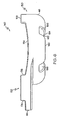
- FIGS. 5 and 6 show another embodiment of patella resectioning guide 140. Similar to the embodiment of FIGS. 2 to 4 , the resectioning guide 140 has a medial side 44 and a lateral side 46. The resectioning guide 140 also includes a body 150 and a cutting guide 152, which is secured to the body 150 and positioned on the medial side 44 of the resectioning guide 140. The resectioning guide 140 is formed as a single monolithic component from a polymeric material such as those discussed above with reference to the embodiment of FIGS. 2 to 4 .
- the body 150 includes a bone-facing surface 154 having a customised patient-specific negative contour 156 defined therein. Similar to the negative contour 56, the negative contour 156 is configured to receive the corresponding positive contour 49 of the posterior side 48 of the patient's patella 42.
- the body 150 also includes a sidewall 158 extending upwardly from the bone-facing surface 154. The sidewall 158 is positioned on the lateral side 46 of the resectioning guide 140 such that the customised patient-specific contour 156 is positioned between the sidewall 158 and the cutting guide 152.
- the body 150 also includes an outer surface 160 opposite the bone-facing surface 154.
- the outer surface 160 includes a recess 162 shaped to receive an end of a clamp (not shown) or other tool for holding the patient's patella 42 in the resectioning guide 140.
- the recess 162 has a round indentation 164 and a pair of slots 166 formed in the outer surface 160.
- the round indentation 164 and the slots 166 are sized to receive the clamp (not shown) operable to secure the patella 42 to the body 150.
- the recess 162 includes indentations and slots for use in holding the patient's patella 42 in the resectioning guide 140.
- the cutting guide 152 includes a cutting slot 170 sized to receive a cutting saw blade (not shown).
- the cutting slot 170 extends from an opening 174 defined in the medial side 44 of the resectioning guide 140 to an opening (not shown) in a bone-facing surface 176 of the cutting guide 152.
- the cutting slot 170 defines a resectioning plane 178 extending through the patient's patella 42 when the patella 42 is received in the customised patient-specific negative contour 156 of the body 150.
- the sidewall 158 intersects with the resectioning plane 178 and extends upwardly from the body 150 a length sufficient to prevent a cutting saw blade (not shown) from extending beyond the lateral side 46 of the resectioning guide 140 during use.
- the tendons 100 of the patient may contact the bone-facing surface 154 of the body 150 when the positive contour 49 of the posterior side 48 of the patient's patella 42 is received in the negative contour 156.
- the bone-facing surface 154 has a medial-to-lateral concave contour (see FIG. 6 ) which is configured to receive a portion of tendons 100.
- an orthopaedic surgeon may secure the patella 42 to the body 150 using the clamp or other securing means. The surgeon may then insert the cutting saw blade into the opening 174. The blade passes through the cutting slot 170 and contacts the medial side of the portion of the patella 42 received in the negative contour 156. Following the resectioning plane 178 defined by the cutting slot 170, the surgeon may perform a resectioning cut on the patient's patella 42 by moving the blade back and forth within the cutting slot 170. In this way, the blade is captured within the cutting guide 152 while the surgeon performs the resectioning cut. As the blade cuts through the patella 42, the sidewall 158 prevents the surgeon from pushing the blade beyond the resectioning guide 140.
- the customised patient-specific patella resectioning guide may be embodied as a patella resectioning guide 240. Similar to the embodiments of FIGS. 2 to 6 , the resectioning guide 240 has a medial side 44 and a lateral side 46. The resectioning guide 240 also includes a body 250 and a non-captured cutting guide 252 that is secured to the body 250 and formed on the medial side 44. Like the embodiment of FIGS. 5 and 6 , the patella resectioning guide 240 is formed as a single monolithic component.
- the body 250 includes a bone-facing surface 254 having a customised patient-specific negative contour 256 defined therein.
- the negative contour 256 is configured to receive the corresponding positive contour 49 of the posterior side 48 of the patient's patella 42.
- the body 250 also includes a sidewall 258 extending upwardly from the bone-facing surface 254.
- the sidewall 258 is positioned on the lateral side 46 of the resectioning guide 240 such that the customised patient-specific negative contour 256 is positioned between the cutting guide 252 and the sidewall 258.
- the body 250 also includes an outer surface 260 opposite the bone-facing surface 254.
- the outer surface 260 includes a recess 262 shaped to receive an end of a clamp (not shown) or other tool for holding the patient's patella in the resectioning guide 240.
- the recess 262 includes indentations and slots for use in holding the patient's patella 42 in the resectioning guide 240.
- the non-captured cutting guide 252 includes a cutting surface 270 and the bone-facing surface 254.
- the cutting surface 270 extends from the medial side 44 to the bone-facing surface 254 of the body 250. That is, the cutting surface 270 and the bone-facing surface 254 are co-planar with each other.
- the cutting surface 270 defines a resectioning plane 272 that the surgeon follows to perform a resectioning cut on the patient's patella 42 when the patella 42 is received in the customised patient-specific negative contour 256 of the body 250.
- the sidewall 258 intersects with the resectioning plane 272 and extends upwardly from the body 150 a length sufficient to prevent a cutting saw blade (not shown) from extending beyond the lateral side 46 of the resectioning guide 240 during use.
Landscapes
- Health & Medical Sciences (AREA)
- Surgery (AREA)
- Life Sciences & Earth Sciences (AREA)
- Medical Informatics (AREA)
- Animal Behavior & Ethology (AREA)
- Oral & Maxillofacial Surgery (AREA)
- Nuclear Medicine, Radiotherapy & Molecular Imaging (AREA)
- Veterinary Medicine (AREA)
- Public Health (AREA)
- Engineering & Computer Science (AREA)
- Biomedical Technology (AREA)
- Heart & Thoracic Surgery (AREA)
- General Health & Medical Sciences (AREA)
- Molecular Biology (AREA)
- Dentistry (AREA)
- Orthopedic Medicine & Surgery (AREA)
- Physical Education & Sports Medicine (AREA)
- Transplantation (AREA)
- Pathology (AREA)
- Surgical Instruments (AREA)
- Prostheses (AREA)
- Medicines Containing Plant Substances (AREA)
- Pyrane Compounds (AREA)
- Separation By Low-Temperature Treatments (AREA)
- Superconductors And Manufacturing Methods Therefor (AREA)
- Nitrogen And Oxygen Or Sulfur-Condensed Heterocyclic Ring Systems (AREA)
Claims (8)
- Anordnung mit einer Patellaresektionsfuhrung, die eine Patellaresektionsführung (40; 140; 240) und eine Klammer aufweist, wobei die Patellaresektionsführung aufweist:(i) einen Körper (50; 150; 250), der eine zum Knochen weisende Fläche (54) mit einer negativen Kontur (56), die so ausgelegt ist, dass sie einen Bereich einer hinten liegenden Seite der Patella (42) eines Patienten aufnimmt, welcher eine entsprechende positive Kontur hat, und eine der zum Knochen weisenden Fläche gegenüberstehende Außenfläche (58; 160; 260), die eine darin gebildete Vertiefung (60; 162; 262) hat, umfasst und(ii) eine Schneidführung (52; 152; 252), die an den Körper gekoppelt ist, die einen Schneidschlitz (70; 170), der darin definiert ist, oder eine nicht greifende Schneidfläche (270) umfasst, wobei der Schneidschlitz oder die Schneidfläche eine Resektionsebene (72; 272) definieren, wobei die Schneidfläche derart angeordnet ist, dass die Resektionsebene sich durch die Patella des Patienten erstreckt, wenn die Patella in der negativen Kontur des Körpers aufgenommen ist,wobei die Klammer ein Ende hat, das in der Vertiefung aufgenommen werden kann, wenn sie verwendet wird, um die Patella des Patienten in der negativen Kontur des Körpers zu halten,
dadurch gekennzeichnet, dass die Außenfläche des Körpers ein Paar sich zwischen der Vertiefung und der Kante der Außenfläche erstreckende Nuten (62; 166; 262) hat, die so bemessen sind, dass sie die Klammer aufnehmen, wenn das Ende der Klammer in der Vertiefung aufgenommen ist. - Anordnung nach Anspruch 1, bei der der Körper (50) aus einem polymeren Material gebildet ist und die Schneidführung (52) über den Körper der Patellaresektionsführung geformt ist.
- Anordnung nach Anspruch 1, mit:einer medialen Seite (44), die der medialen Seite der Patella (42) des Patienten entspricht, wenn die Patella in der negativen Kontur (56) des Körpers (50) aufgenommen ist, undeine laterale Seite (46), die der lateralen Seite der Patella des Patienten entspricht, wenn die Patella in der negativen Kontur des Körpers aufgenommen ist,wobei der Schneidschlitz (70) der Schneidführung eine erste Öffnung (74) auf der medialen Seite der Resektionsführung (40) umfasst, wobei die erste Öffnung so bemessen ist, dass sie ein Schneidsägeblatt aufnimmt.
- Anordnung nach Anspruch 3, bei der der Schneidschlitz (70) der Schneidführung (52) eine zweite Öffnung (76) auf der lateralen Seite der Resektionsführung (40) umfasst, wobei die zweite Öffnung so bemessen ist, dass sie ein Schneidsägeblatt aufnimmt.
- Anordnung nach Anspruch 3, die eine Vertiefung (92) hat, welche auf der medialen Seite (44) der Resektionsführung (40) gebildet ist, und bei der sich die Vertiefung von der Außenfläche (58) des Körpers (50) zu dem Schneidschlitz (70) der Schneidführung (52) erstreckt.
- Anordnung nach Anspruch 3, bei der der Körper (150) eine Seitenwand (158) umfasst, die sich von der zum Knochen weisenden Fläche (154) nach oben erstreckt und die Resektionsebene (178) schneidet, um zu verhindern, dass sich das Schneidsägeblatt über den Körper hinaus erstreckt.
- Anordnung nach Anspruch 6, bei der:die Seitenwand (158) auf der lateralen Seite (46) der Resektionsführung (140) angeordnet ist unddie Schneidführung (152) auf der medialen Seite (52) der Resektionsführung derart angeordnet ist, dass die negative Kontur (56) des Körpers sich zwischen der Schneidführung und der Seitenwand befindet.
- Anordnung nach Anspruch 1, bei der der Körper (50) und die Schneidführung (52) als eine einzige monolithische Komponente gebildet sind.
Priority Applications (2)
| Application Number | Priority Date | Filing Date | Title |
|---|---|---|---|
| EP15150198.8A EP2862525B1 (de) | 2009-01-16 | 2010-01-12 | Patellaresektionsführung |
| EP11184387.6A EP2404560B1 (de) | 2009-01-16 | 2010-01-12 | Patellaresektionsführung |
Applications Claiming Priority (1)
| Application Number | Priority Date | Filing Date | Title |
|---|---|---|---|
| US12/355,235 US20100185202A1 (en) | 2009-01-16 | 2009-01-16 | Customized patient-specific patella resectioning guide |
Related Child Applications (3)
| Application Number | Title | Priority Date | Filing Date |
|---|---|---|---|
| EP11184387.6A Division EP2404560B1 (de) | 2009-01-16 | 2010-01-12 | Patellaresektionsführung |
| EP15150198.8A Division EP2862525B1 (de) | 2009-01-16 | 2010-01-12 | Patellaresektionsführung |
| EP11184387.6 Division-Into | 2011-10-07 |
Publications (2)
| Publication Number | Publication Date |
|---|---|
| EP2208470A1 EP2208470A1 (de) | 2010-07-21 |
| EP2208470B1 true EP2208470B1 (de) | 2012-02-29 |
Family
ID=42102981
Family Applications (3)
| Application Number | Title | Priority Date | Filing Date |
|---|---|---|---|
| EP15150198.8A Active EP2862525B1 (de) | 2009-01-16 | 2010-01-12 | Patellaresektionsführung |
| EP10150487A Active EP2208470B1 (de) | 2009-01-16 | 2010-01-12 | Patellaresektionsführung |
| EP11184387.6A Active EP2404560B1 (de) | 2009-01-16 | 2010-01-12 | Patellaresektionsführung |
Family Applications Before (1)
| Application Number | Title | Priority Date | Filing Date |
|---|---|---|---|
| EP15150198.8A Active EP2862525B1 (de) | 2009-01-16 | 2010-01-12 | Patellaresektionsführung |
Family Applications After (1)
| Application Number | Title | Priority Date | Filing Date |
|---|---|---|---|
| EP11184387.6A Active EP2404560B1 (de) | 2009-01-16 | 2010-01-12 | Patellaresektionsführung |
Country Status (9)
| Country | Link |
|---|---|
| US (1) | US20100185202A1 (de) |
| EP (3) | EP2862525B1 (de) |
| JP (1) | JP5570826B2 (de) |
| CN (1) | CN101797175B (de) |
| AT (1) | ATE547054T1 (de) |
| AU (1) | AU2010200130B2 (de) |
| DK (1) | DK2208470T3 (de) |
| ES (1) | ES2379592T3 (de) |
| ZA (1) | ZA201000324B (de) |
Families Citing this family (138)
| Publication number | Priority date | Publication date | Assignee | Title |
|---|---|---|---|---|
| US8241293B2 (en) | 2006-02-27 | 2012-08-14 | Biomet Manufacturing Corp. | Patient specific high tibia osteotomy |
| US20150335438A1 (en) | 2006-02-27 | 2015-11-26 | Biomet Manufacturing, Llc. | Patient-specific augments |
| US8591516B2 (en) | 2006-02-27 | 2013-11-26 | Biomet Manufacturing, Llc | Patient-specific orthopedic instruments |
| US9113971B2 (en) | 2006-02-27 | 2015-08-25 | Biomet Manufacturing, Llc | Femoral acetabular impingement guide |
| US8603180B2 (en) | 2006-02-27 | 2013-12-10 | Biomet Manufacturing, Llc | Patient-specific acetabular alignment guides |
| US8377066B2 (en) | 2006-02-27 | 2013-02-19 | Biomet Manufacturing Corp. | Patient-specific elbow guides and associated methods |
| US8535387B2 (en) | 2006-02-27 | 2013-09-17 | Biomet Manufacturing, Llc | Patient-specific tools and implants |
| US8568487B2 (en) | 2006-02-27 | 2013-10-29 | Biomet Manufacturing, Llc | Patient-specific hip joint devices |
| US8298237B2 (en) | 2006-06-09 | 2012-10-30 | Biomet Manufacturing Corp. | Patient-specific alignment guide for multiple incisions |
| US9345548B2 (en) | 2006-02-27 | 2016-05-24 | Biomet Manufacturing, Llc | Patient-specific pre-operative planning |
| US9907659B2 (en) | 2007-04-17 | 2018-03-06 | Biomet Manufacturing, Llc | Method and apparatus for manufacturing an implant |
| US8608749B2 (en) | 2006-02-27 | 2013-12-17 | Biomet Manufacturing, Llc | Patient-specific acetabular guides and associated instruments |
| US8608748B2 (en) | 2006-02-27 | 2013-12-17 | Biomet Manufacturing, Llc | Patient specific guides |
| US8864769B2 (en) | 2006-02-27 | 2014-10-21 | Biomet Manufacturing, Llc | Alignment guides with patient-specific anchoring elements |
| US9918740B2 (en) | 2006-02-27 | 2018-03-20 | Biomet Manufacturing, Llc | Backup surgical instrument system and method |
| US9173661B2 (en) | 2006-02-27 | 2015-11-03 | Biomet Manufacturing, Llc | Patient specific alignment guide with cutting surface and laser indicator |
| US8070752B2 (en) | 2006-02-27 | 2011-12-06 | Biomet Manufacturing Corp. | Patient specific alignment guide and inter-operative adjustment |
| US8858561B2 (en) | 2006-06-09 | 2014-10-14 | Blomet Manufacturing, LLC | Patient-specific alignment guide |
| US8473305B2 (en) | 2007-04-17 | 2013-06-25 | Biomet Manufacturing Corp. | Method and apparatus for manufacturing an implant |
| US10278711B2 (en) | 2006-02-27 | 2019-05-07 | Biomet Manufacturing, Llc | Patient-specific femoral guide |
| US8133234B2 (en) | 2006-02-27 | 2012-03-13 | Biomet Manufacturing Corp. | Patient specific acetabular guide and method |
| US8282646B2 (en) | 2006-02-27 | 2012-10-09 | Biomet Manufacturing Corp. | Patient specific knee alignment guide and associated method |
| US8407067B2 (en) | 2007-04-17 | 2013-03-26 | Biomet Manufacturing Corp. | Method and apparatus for manufacturing an implant |
| US9339278B2 (en) | 2006-02-27 | 2016-05-17 | Biomet Manufacturing, Llc | Patient-specific acetabular guides and associated instruments |
| US8092465B2 (en) | 2006-06-09 | 2012-01-10 | Biomet Manufacturing Corp. | Patient specific knee alignment guide and associated method |
| US9289253B2 (en) | 2006-02-27 | 2016-03-22 | Biomet Manufacturing, Llc | Patient-specific shoulder guide |
| US7967868B2 (en) | 2007-04-17 | 2011-06-28 | Biomet Manufacturing Corp. | Patient-modified implant and associated method |
| US9795399B2 (en) | 2006-06-09 | 2017-10-24 | Biomet Manufacturing, Llc | Patient-specific knee alignment guide and associated method |
| CA2945266C (en) | 2007-08-17 | 2021-11-02 | Zimmer, Inc. | Implant design analysis suite |
| US8265949B2 (en) | 2007-09-27 | 2012-09-11 | Depuy Products, Inc. | Customized patient surgical plan |
| US8357111B2 (en) | 2007-09-30 | 2013-01-22 | Depuy Products, Inc. | Method and system for designing patient-specific orthopaedic surgical instruments |
| ES2838598T3 (es) | 2007-09-30 | 2021-07-02 | Depuy Products Inc | Instrumento quirúrgico ortopédico personalizado y específico del paciente |
| US9173662B2 (en) | 2007-09-30 | 2015-11-03 | DePuy Synthes Products, Inc. | Customized patient-specific tibial cutting blocks |
| US9138239B2 (en) | 2007-09-30 | 2015-09-22 | DePuy Synthes Products, Inc. | Customized patient-specific tibial cutting blocks |
| WO2009076296A2 (en) | 2007-12-06 | 2009-06-18 | Smith & Nephew, Inc. | Systems and methods for determining the mechanical axis of a femur |
| US8777875B2 (en) | 2008-07-23 | 2014-07-15 | Otismed Corporation | System and method for manufacturing arthroplasty jigs having improved mating accuracy |
| US8737700B2 (en) | 2007-12-18 | 2014-05-27 | Otismed Corporation | Preoperatively planning an arthroplasty procedure and generating a corresponding patient specific arthroplasty resection guide |
| US8160345B2 (en) | 2008-04-30 | 2012-04-17 | Otismed Corporation | System and method for image segmentation in generating computer models of a joint to undergo arthroplasty |
| US8617171B2 (en) | 2007-12-18 | 2013-12-31 | Otismed Corporation | Preoperatively planning an arthroplasty procedure and generating a corresponding patient specific arthroplasty resection guide |
| US8715291B2 (en) | 2007-12-18 | 2014-05-06 | Otismed Corporation | Arthroplasty system and related methods |
| US8311306B2 (en) | 2008-04-30 | 2012-11-13 | Otismed Corporation | System and method for image segmentation in generating computer models of a joint to undergo arthroplasty |
| US9408618B2 (en) | 2008-02-29 | 2016-08-09 | Howmedica Osteonics Corporation | Total hip replacement surgical guide tool |
| US8617175B2 (en) | 2008-12-16 | 2013-12-31 | Otismed Corporation | Unicompartmental customized arthroplasty cutting jigs and methods of making the same |
| US8170641B2 (en) | 2009-02-20 | 2012-05-01 | Biomet Manufacturing Corp. | Method of imaging an extremity of a patient |
| CA2753485C (en) | 2009-02-25 | 2014-01-14 | Mohamed Rashwan Mahfouz | Customized orthopaedic implants and related methods |
| US9078755B2 (en) | 2009-02-25 | 2015-07-14 | Zimmer, Inc. | Ethnic-specific orthopaedic implants and custom cutting jigs |
| DE102009028503B4 (de) | 2009-08-13 | 2013-11-14 | Biomet Manufacturing Corp. | Resektionsschablone zur Resektion von Knochen, Verfahren zur Herstellung einer solchen Resektionsschablone und Operationsset zur Durchführung von Kniegelenk-Operationen |
| EP2493396B1 (de) | 2009-10-29 | 2016-11-23 | Zimmer, Inc. | Patientenspezifische fräsführung |
| EP2538864B1 (de) | 2010-02-25 | 2018-10-31 | DePuy Products, Inc. | Angepasste patientenspezifische knochenschneideblöcke |
| WO2011106407A1 (en) * | 2010-02-25 | 2011-09-01 | Depuy Products, Inc. | Method of fabricating customized patient-specific bone cutting blocks |
| EP2538853A4 (de) | 2010-02-25 | 2016-07-27 | Depuy Products Inc | Angepasste patientenspezifische knochenschneideblöcke |
| US8632547B2 (en) | 2010-02-26 | 2014-01-21 | Biomet Sports Medicine, Llc | Patient-specific osteotomy devices and methods |
| US9066727B2 (en) | 2010-03-04 | 2015-06-30 | Materialise Nv | Patient-specific computed tomography guides |
| US9386994B2 (en) | 2010-06-11 | 2016-07-12 | Smith & Nephew, Inc. | Patient-matched instruments |
| US9271744B2 (en) | 2010-09-29 | 2016-03-01 | Biomet Manufacturing, Llc | Patient-specific guide for partial acetabular socket replacement |
| CA2815654C (en) | 2010-10-29 | 2019-02-19 | The Cleveland Clinic Foundation | System and method for assisting with attachment of a stock implant to a patient tissue |
| EP3636174B1 (de) | 2010-10-29 | 2021-09-08 | The Cleveland Clinic Foundation | System zur verbindung einer führungshilfe mit einem patientengewebe |
| EP2632350B1 (de) | 2010-10-29 | 2021-09-22 | The Cleveland Clinic Foundation | System zur präoperativen planung und bereitstellung patientenspezifischer chirurgischer hilfsmittel |
| WO2012058353A1 (en) | 2010-10-29 | 2012-05-03 | The Cleveland Clinic Foundation | System and method for assisting with arrangement of a stock instrument with respect to a patient tissue |
| US9968376B2 (en) | 2010-11-29 | 2018-05-15 | Biomet Manufacturing, Llc | Patient-specific orthopedic instruments |
| JP6253990B2 (ja) * | 2011-02-25 | 2017-12-27 | コリン リミテッドCorin Limited | 患者の関節用の整形外科インプラントの位置合わせのための位置合わせ情報データを提供するコンピュータ実行方法、コンピュータ装置、およびコンピュータ読み取り可能な記録媒体 |
| US9241745B2 (en) | 2011-03-07 | 2016-01-26 | Biomet Manufacturing, Llc | Patient-specific femoral version guide |
| US8715289B2 (en) | 2011-04-15 | 2014-05-06 | Biomet Manufacturing, Llc | Patient-specific numerically controlled instrument |
| US9675400B2 (en) | 2011-04-19 | 2017-06-13 | Biomet Manufacturing, Llc | Patient-specific fracture fixation instrumentation and method |
| US8956364B2 (en) | 2011-04-29 | 2015-02-17 | Biomet Manufacturing, Llc | Patient-specific partial knee guides and other instruments |
| US8668700B2 (en) | 2011-04-29 | 2014-03-11 | Biomet Manufacturing, Llc | Patient-specific convertible guides |
| WO2012154914A1 (en) * | 2011-05-11 | 2012-11-15 | The Cleveland Clinic Foundation | Generating patient specific instruments for use as surgical aids |
| EP3141196B1 (de) | 2011-05-19 | 2020-04-08 | The Cleveland Clinic Foundation | Vorrichtung zur referenzindikation für ein patientengewebe |
| US8532807B2 (en) | 2011-06-06 | 2013-09-10 | Biomet Manufacturing, Llc | Pre-operative planning and manufacturing method for orthopedic procedure |
| US9084618B2 (en) | 2011-06-13 | 2015-07-21 | Biomet Manufacturing, Llc | Drill guides for confirming alignment of patient-specific alignment guides |
| EP2720631B1 (de) | 2011-06-16 | 2022-01-26 | Smith&Nephew, Inc. | Chirurgische ausrichtung mittels referenzen |
| US8641721B2 (en) | 2011-06-30 | 2014-02-04 | DePuy Synthes Products, LLC | Customized patient-specific orthopaedic pin guides |
| US8764760B2 (en) | 2011-07-01 | 2014-07-01 | Biomet Manufacturing, Llc | Patient-specific bone-cutting guidance instruments and methods |
| US20130001121A1 (en) | 2011-07-01 | 2013-01-03 | Biomet Manufacturing Corp. | Backup kit for a patient-specific arthroplasty kit assembly |
| US8597365B2 (en) | 2011-08-04 | 2013-12-03 | Biomet Manufacturing, Llc | Patient-specific pelvic implants for acetabular reconstruction |
| US9066734B2 (en) | 2011-08-31 | 2015-06-30 | Biomet Manufacturing, Llc | Patient-specific sacroiliac guides and associated methods |
| US9295497B2 (en) | 2011-08-31 | 2016-03-29 | Biomet Manufacturing, Llc | Patient-specific sacroiliac and pedicle guides |
| US9386993B2 (en) | 2011-09-29 | 2016-07-12 | Biomet Manufacturing, Llc | Patient-specific femoroacetabular impingement instruments and methods |
| EP2770918B1 (de) | 2011-10-27 | 2017-07-19 | Biomet Manufacturing, LLC | Patientenspezifische glenoidale führungen |
| US9554910B2 (en) | 2011-10-27 | 2017-01-31 | Biomet Manufacturing, Llc | Patient-specific glenoid guide and implants |
| KR20130046336A (ko) | 2011-10-27 | 2013-05-07 | 삼성전자주식회사 | 디스플레이장치의 멀티뷰 디바이스 및 그 제어방법과, 디스플레이 시스템 |
| US9451973B2 (en) | 2011-10-27 | 2016-09-27 | Biomet Manufacturing, Llc | Patient specific glenoid guide |
| US9301812B2 (en) | 2011-10-27 | 2016-04-05 | Biomet Manufacturing, Llc | Methods for patient-specific shoulder arthroplasty |
| WO2013060842A1 (en) * | 2011-10-28 | 2013-05-02 | Materialise N.V. | Guides with pressure points |
| US9603604B2 (en) | 2011-10-28 | 2017-03-28 | Symmetry Medical Manufacturing, Inc. | Orthopaedic cutting block |
| EP2806810B1 (de) | 2012-01-24 | 2018-03-28 | Zimmer, Inc. | Verfahren und system zur erzeugung eines patientenspezifischen instrumentariums für eine knorpeltransplantatübertragung |
| US9237950B2 (en) | 2012-02-02 | 2016-01-19 | Biomet Manufacturing, Llc | Implant with patient-specific porous structure |
| EP3251620B1 (de) | 2012-03-28 | 2021-04-14 | Orthosoft ULC | Glenoidimplantatchirurgie unter verwendung eines patientenspezifischen instruments |
| WO2013165558A1 (en) | 2012-05-03 | 2013-11-07 | DePuy Synthes Products, LLC | Surgical guides from scanned implant data |
| WO2013173926A1 (en) | 2012-05-24 | 2013-11-28 | Zimmer, Inc. | Patient-specific instrumentation and method for articular joint repair |
| EP2874550B1 (de) | 2012-07-23 | 2017-09-27 | Orthosoft, Inc. | Patientenspezifisches instrumentarium für implantatrevision |
| CA2887130C (en) | 2012-07-24 | 2020-03-24 | Orthosoft Inc. | Patient specific instrumentation with mems in surgery |
| US9411939B2 (en) | 2012-09-12 | 2016-08-09 | DePuy Synthes Products, Inc. | Method for producing patient-specific plate |
| US9402637B2 (en) | 2012-10-11 | 2016-08-02 | Howmedica Osteonics Corporation | Customized arthroplasty cutting guides and surgical methods using the same |
| US9060788B2 (en) | 2012-12-11 | 2015-06-23 | Biomet Manufacturing, Llc | Patient-specific acetabular guide for anterior approach |
| US9204977B2 (en) | 2012-12-11 | 2015-12-08 | Biomet Manufacturing, Llc | Patient-specific acetabular guide for anterior approach |
| US9839438B2 (en) | 2013-03-11 | 2017-12-12 | Biomet Manufacturing, Llc | Patient-specific glenoid guide with a reusable guide holder |
| US9579107B2 (en) | 2013-03-12 | 2017-02-28 | Biomet Manufacturing, Llc | Multi-point fit for patient specific guide |
| US9826981B2 (en) | 2013-03-13 | 2017-11-28 | Biomet Manufacturing, Llc | Tangential fit of patient-specific guides |
| US9498233B2 (en) | 2013-03-13 | 2016-11-22 | Biomet Manufacturing, Llc. | Universal acetabular guide and associated hardware |
| US9517145B2 (en) | 2013-03-15 | 2016-12-13 | Biomet Manufacturing, Llc | Guide alignment system and method |
| CA2908780A1 (en) | 2013-06-11 | 2014-12-18 | Orthosoft Inc. | Computer assisted subchondral injection |
| EP3007655B1 (de) | 2013-06-11 | 2020-09-02 | Orthosoft ULC | Positionierbesteck für hüftgelenkpfanneprothese |
| CA2925299C (en) | 2013-09-25 | 2022-07-26 | Zimmer, Inc. | Patient specific instrumentation (psi) for orthopedic surgery and systems and methods for using x-rays to produce same |
| US20150112349A1 (en) | 2013-10-21 | 2015-04-23 | Biomet Manufacturing, Llc | Ligament Guide Registration |
| GB201320745D0 (en) * | 2013-11-25 | 2014-01-08 | Darwood Alastair | A method and apparatus for the intraoperative production of a surgical guide |
| US10282488B2 (en) | 2014-04-25 | 2019-05-07 | Biomet Manufacturing, Llc | HTO guide with optional guided ACL/PCL tunnels |
| CA2939934A1 (en) | 2014-04-30 | 2015-11-05 | Zimmer, Inc. | Acetabular cup impacting using patient-specific instrumentation |
| US9408616B2 (en) | 2014-05-12 | 2016-08-09 | Biomet Manufacturing, Llc | Humeral cut guide |
| WO2015187822A1 (en) | 2014-06-03 | 2015-12-10 | Zimmer, Inc. | Patient-specific cutting block and method of manufacturing same |
| US9561040B2 (en) | 2014-06-03 | 2017-02-07 | Biomet Manufacturing, Llc | Patient-specific glenoid depth control |
| US9839436B2 (en) | 2014-06-03 | 2017-12-12 | Biomet Manufacturing, Llc | Patient-specific glenoid depth control |
| US9833245B2 (en) | 2014-09-29 | 2017-12-05 | Biomet Sports Medicine, Llc | Tibial tubercule osteotomy |
| US9826994B2 (en) | 2014-09-29 | 2017-11-28 | Biomet Manufacturing, Llc | Adjustable glenoid pin insertion guide |
| FR3027503A1 (fr) * | 2014-10-24 | 2016-04-29 | Aston Medical | Dispositif pour la preparation d'une rotule pour la mise en place d'un implant rotulien |
| CN104546060B (zh) * | 2015-01-26 | 2017-02-01 | 北京大学第三医院 | 一种用于膝关节置换的髌骨截骨导航模板及制作方法 |
| CA2974837A1 (en) | 2015-02-02 | 2016-08-11 | Orthosoft Inc. | Acetabulum rim digitizer device and method |
| CN107405169B (zh) | 2015-03-25 | 2021-01-26 | 奥尔索夫特无限责任公司 | 用于帮助在诸如肩胛骨之类的薄骨骼中的植入物放置的系统 |
| US9820868B2 (en) | 2015-03-30 | 2017-11-21 | Biomet Manufacturing, Llc | Method and apparatus for a pin apparatus |
| CA2986780C (en) | 2015-05-28 | 2023-07-04 | Zimmer, Inc. | Patient-specific bone grafting system and method |
| US10226262B2 (en) | 2015-06-25 | 2019-03-12 | Biomet Manufacturing, Llc | Patient-specific humeral guide designs |
| US10568647B2 (en) | 2015-06-25 | 2020-02-25 | Biomet Manufacturing, Llc | Patient-specific humeral guide designs |
| WO2017008032A1 (en) | 2015-07-08 | 2017-01-12 | Zimmer, Inc. | Patient-specific instrumentation for implant revision surgery |
| CN105193475B (zh) * | 2015-08-18 | 2017-07-07 | 长沙市第三医院 | 个体化截骨导板套件及其设计方法 |
| CN108348340B (zh) | 2015-09-30 | 2021-08-10 | 捷迈有限公司 | 用于髌骨表面修复术的患者特定器械和方法 |
| US10624764B2 (en) | 2015-11-26 | 2020-04-21 | Orthosoft Ulc | System and method for the registration of an anatomical feature |
| US10874404B2 (en) | 2016-12-30 | 2020-12-29 | DePuy Synthes Products, Inc. | Customized patient-specific surgical instruments and method |
| US10251654B2 (en) | 2016-12-30 | 2019-04-09 | DePuy Synthes Products, Inc. | Customized patient-specific surgical instrument with metallic insert |
| US10722310B2 (en) | 2017-03-13 | 2020-07-28 | Zimmer Biomet CMF and Thoracic, LLC | Virtual surgery planning system and method |
| US11576725B2 (en) | 2017-12-12 | 2023-02-14 | Orthosoft Ulc | Patient-specific instrumentation for implant revision surgery |
| US10716581B2 (en) | 2018-01-24 | 2020-07-21 | DePuy Synthes Products, Inc. | Method of designing and manufacturing low-profile customized patient-specific orthopaedic surgical instruments |
| US10631878B2 (en) | 2018-01-24 | 2020-04-28 | DePuy Synthes Products, Inc. | Customized patient-specific anterior-posterior chamfer block and method |
| US10537343B2 (en) | 2018-01-24 | 2020-01-21 | DePuy Synthes Products, Inc. | Low-profile metallic customized patient-specific orthopaedic surgical instruments |
| US11051829B2 (en) | 2018-06-26 | 2021-07-06 | DePuy Synthes Products, Inc. | Customized patient-specific orthopaedic surgical instrument |
| US11304710B2 (en) | 2019-12-28 | 2022-04-19 | DePuy Synthes Products, Inc. | Customized patient-specific contact segments for orthopaedic surgical instrument using bone silhouette curves |
| US11819280B2 (en) | 2020-09-30 | 2023-11-21 | DePuy Synthes Products, Inc. | Customized patient-specific orthopaedic surgical instrument using patient-specific contacting bodies and parametric fixed geometry |
| CA3131443A1 (fr) * | 2021-09-21 | 2023-03-21 | Services Medicaux Georges Sioufi Inc. | Equipement d'operation pour chirurgie du genou, salle d'operation pourvue d'un tel equipment, kit pour assembler, et methodes d'assemblage, d'operation et d'utilisation correspondantes |
| EP4245242A1 (de) * | 2022-03-18 | 2023-09-20 | Stryker Australia PTY LTD | Knochenresektionsbewertung und -planung |
Family Cites Families (109)
| Publication number | Priority date | Publication date | Assignee | Title |
|---|---|---|---|---|
| US2702550A (en) * | 1953-11-25 | 1955-02-22 | Orthopedic Frame Company | Surgical instrument |
| US3229372A (en) * | 1964-01-23 | 1966-01-18 | Joseph M Quashnock | Goniometer |
| US3298410A (en) * | 1964-01-31 | 1967-01-17 | Morifuji Haguruma Seisakusho C | Screw holder structure for use with screw drivers |
| US3624747A (en) * | 1969-05-01 | 1971-11-30 | Mcknight Charles A | Surgical instrument for rupturing membranes |
| GB1325534A (en) * | 1969-08-11 | 1973-08-01 | Nat Res Dev | Prosthetic acetabular devices |
| US3685720A (en) * | 1970-07-28 | 1972-08-22 | Charles E Brady | Package for sterilized products |
| US3774244A (en) * | 1972-02-08 | 1973-11-27 | Relief Ruptured And Crippled S | Knee-joint prosthesis |
| US3869731A (en) * | 1973-02-14 | 1975-03-11 | Univ California | Articulated two-part prosthesis replacing the knee joint |
| US3840904A (en) * | 1973-04-30 | 1974-10-15 | R Tronzo | Acetabular cup prosthesis |
| US3901298A (en) * | 1974-04-05 | 1975-08-26 | John B Eby | Fastener holding attachment |
| US3920022A (en) * | 1974-04-19 | 1975-11-18 | Macey A Pastor | Surgical instrument |
| US3903549A (en) * | 1974-06-12 | 1975-09-09 | William Minor Deyerle | Acetabular cup prosthesis component for total or subtotal hip prosthesis system |
| US3994287A (en) * | 1974-07-01 | 1976-11-30 | Centre De Recherche Industrielle Du Quebec | Trocar |
| US3941127A (en) * | 1974-10-03 | 1976-03-02 | Froning Edward C | Apparatus and method for stereotaxic lateral extradural disc puncture |
| US4085466A (en) * | 1974-11-18 | 1978-04-25 | National Research Development Corporation | Prosthetic joint device |
| US3965950A (en) * | 1975-03-20 | 1976-06-29 | Macdonald Murdo A | Fastener driver and fastener holding nosepiece |
| US4055862A (en) * | 1976-01-23 | 1977-11-01 | Zimmer Usa, Inc. | Human body implant of graphitic carbon fiber reinforced ultra-high molecular weight polyethylene |
| US4081866A (en) * | 1977-02-02 | 1978-04-04 | Howmedica, Inc. | Total anatomical knee prosthesis |
| US4140161A (en) * | 1977-06-15 | 1979-02-20 | Minnesota Mining And Manufacturing Company | Screw holding and driving device |
| US4197886A (en) * | 1977-09-06 | 1980-04-15 | Clyde Corporation | Fastener driving tool and fastener holding nosepiece |
| US4311145A (en) * | 1979-07-16 | 1982-01-19 | Neomed, Inc. | Disposable electrosurgical instrument |
| US4386609A (en) * | 1979-12-17 | 1983-06-07 | Minnesota Mining And Manufacturing Company | Attaching assembly for an osteotomy saw blade |
| US4373709A (en) * | 1980-09-24 | 1983-02-15 | Whitt Everett D | Surgical limb holder |
| US4349018A (en) * | 1980-12-29 | 1982-09-14 | Chambers Gary R | Osteotomy apparatus |
| DE3142730A1 (de) * | 1981-04-01 | 1982-10-21 | Curt Dipl.-Ing. 1000 Berlin Kranz | "gelenkprothese" |
| US4400833A (en) * | 1981-06-10 | 1983-08-30 | Kurland Kenneth Z | Means and method of implanting bioprosthetics |
| US4501269A (en) * | 1981-12-11 | 1985-02-26 | Washington State University Research Foundation, Inc. | Process for fusing bone joints |
| US4475549A (en) * | 1982-01-18 | 1984-10-09 | Indong Oh | Acetabular cup positioner and method |
| US4509518A (en) * | 1982-02-17 | 1985-04-09 | United States Surgical Corporation | Apparatus for applying surgical clips |
| US4646729A (en) * | 1982-02-18 | 1987-03-03 | Howmedica, Inc. | Prosthetic knee implantation |
| USD273895S (en) * | 1982-02-18 | 1984-05-15 | Howmedica, Inc. | Femoral cutting jig for the implantation of a prosthetic knee |
| USD274091S (en) * | 1982-02-18 | 1984-05-29 | Howmedica, Inc. | Femoral chamfer cutting jig for the implantation of a prosthetic knee |
| DE3213434C1 (de) * | 1982-04-10 | 1983-10-27 | Günther Dr.med. 7400 Tübingen Aldinger | Verfahren zur Herstellung individuell gestalteter Endoprothesen oder Implantate |
| US4436684A (en) * | 1982-06-03 | 1984-03-13 | Contour Med Partners, Ltd. | Method of forming implantable prostheses for reconstructive surgery |
| US4583555A (en) * | 1983-01-03 | 1986-04-22 | Medmetric Corporation | Knee ligament testing system |
| US4567886A (en) * | 1983-01-06 | 1986-02-04 | Petersen Thomas D | Flexion spacer guide for fitting a knee prosthesis |
| US4506393A (en) * | 1983-03-29 | 1985-03-26 | Murphy Stephen B | Method of prosthesis design |
| US4663720A (en) * | 1984-02-21 | 1987-05-05 | Francois Duret | Method of and apparatus for making a prosthesis, especially a dental prosthesis |
| US4621630A (en) * | 1983-04-15 | 1986-11-11 | Pfizer Hospital Products Group, Inc. | Guide for femoral neck osteotomy |
| US4545375A (en) * | 1983-06-10 | 1985-10-08 | Aspen Laboratories, Inc. | Electrosurgical instrument |
| US4549555A (en) * | 1984-02-17 | 1985-10-29 | Orthothronics Limited Partnership | Knee laxity evaluator and motion module/digitizer arrangement |
| US4534365A (en) * | 1984-04-05 | 1985-08-13 | Canadian Ursus Rubber Limited | Apparatus for evaluating foot condition |
| US4565192A (en) * | 1984-04-12 | 1986-01-21 | Shapiro James A | Device for cutting a patella and method therefor |
| US4574794A (en) * | 1984-06-01 | 1986-03-11 | Queen's University At Kingston | Orthopaedic bone cutting jig and alignment device |
| US4583554A (en) * | 1984-06-12 | 1986-04-22 | Medpar Ii | Knee ligament testing device |
| SE450336B (sv) * | 1984-11-28 | 1987-06-22 | Branemark Per Ingvar | Ledprotes for permanent forankring i benvevnaden |
| US4632111A (en) * | 1985-03-21 | 1986-12-30 | Minnesota Mining And Manufacturing Company | Acetabular cup positioning apparatus |
| US4936852A (en) * | 1985-04-30 | 1990-06-26 | Vitek, Inc. | Temporomandibular mini condyle prosthesis |
| CH666178A5 (de) * | 1985-06-12 | 1988-07-15 | Sulzer Ag | Femurkopfprothese. |
| US4711233A (en) * | 1985-06-26 | 1987-12-08 | Brown Byron L | Method and apparatus for cementing an acetabular cup to an acetabulum |
| US4662372A (en) * | 1985-08-12 | 1987-05-05 | Acme United Corporation | Disposable surgical instrument and method of forming |
| US4715860A (en) * | 1985-08-23 | 1987-12-29 | The Regents Of The University Of California | Porous acetabular hip resurfacing |
| US4641648A (en) * | 1985-09-27 | 1987-02-10 | Marshall Shapiro | Surgical instrument |
| EP0243410A1 (de) * | 1985-10-28 | 1987-11-04 | ROGER, Greogory James | Verfahren und vorrichtung zur beseitigung von prothesezement |
| US4721104A (en) * | 1985-12-02 | 1988-01-26 | Dow Corning Wright Corporation | Femoral surface shaping apparatus for posterior-stabilized knee implants |
| US4787383A (en) * | 1985-12-19 | 1988-11-29 | Howmedica, Inc. | Prosthetic knee implantation |
| US4888022A (en) * | 1985-12-30 | 1989-12-19 | Huebsch Donald L | Endoprosthesis |
| US4703751A (en) * | 1986-03-27 | 1987-11-03 | Pohl Kenneth P | Method and apparatus for resecting a distal femoral surface |
| US4913163A (en) * | 1986-03-27 | 1990-04-03 | Roger Gregory J | Measurement of laxity of anterior cruciate ligament |
| DE3707518A1 (de) * | 1986-05-16 | 1987-11-26 | Copf Franz | Prothesenteil sowie verfahren zu seiner herstellung |
| US4936862A (en) * | 1986-05-30 | 1990-06-26 | Walker Peter S | Method of designing and manufacturing a human joint prosthesis |
| US4822365A (en) * | 1986-05-30 | 1989-04-18 | Walker Peter S | Method of design of human joint prosthesis |
| AT387711B (de) * | 1986-07-15 | 1989-03-10 | David Thomas | Knochenfixationsplatte |
| US4791934A (en) * | 1986-08-07 | 1988-12-20 | Picker International, Inc. | Computer tomography assisted stereotactic surgery system and method |
| US4739751A (en) * | 1986-10-03 | 1988-04-26 | Temple University | Apparatus and method for reconstructive surgery |
| US4718413A (en) * | 1986-12-24 | 1988-01-12 | Orthomet, Inc. | Bone cutting guide and methods for using same |
| US4834757A (en) * | 1987-01-22 | 1989-05-30 | Brantigan John W | Prosthetic implant |
| US4719907A (en) * | 1987-03-18 | 1988-01-19 | Orthospec, Inc. | Orthopedic pin placement guide |
| US4961954A (en) * | 1987-04-10 | 1990-10-09 | University Of Florida | Surface modified surgical instruments, devices, implants, contact lenses and the like |
| US4841975A (en) * | 1987-04-15 | 1989-06-27 | Cemax, Inc. | Preoperative planning of bone cuts and joint replacement using radiant energy scan imaging |
| US4834080A (en) * | 1987-09-11 | 1989-05-30 | Brown Byron L | Drill bit guide |
| US4976737A (en) * | 1988-01-19 | 1990-12-11 | Research And Education Institute, Inc. | Bone reconstruction |
| US5035700A (en) * | 1988-02-03 | 1991-07-30 | Pfizer Hospital Products Group, Inc. | Prosthetic knee joint with improved patellar component tracking |
| US4964865A (en) * | 1988-02-03 | 1990-10-23 | Intermedics Orthopedics, Inc. | Glenoid prosthesis and method of use |
| US4893619A (en) * | 1988-02-04 | 1990-01-16 | Intermedics Orthopedics, Inc. | Humeral osteotomy guide |
| US5007936A (en) * | 1988-02-18 | 1991-04-16 | Cemax, Inc. | Surgical method for hip joint replacement |
| US4979949A (en) * | 1988-04-26 | 1990-12-25 | The Board Of Regents Of The University Of Washington | Robot-aided system for surgery |
| US5015247A (en) * | 1988-06-13 | 1991-05-14 | Michelson Gary K | Threaded spinal implant |
| US4860735A (en) * | 1988-08-08 | 1989-08-29 | The General Hospital Corporation | Drill alignment guide for osteoplastic surgery |
| US4896663A (en) * | 1988-10-14 | 1990-01-30 | Boehringer Mannheim Corporation | Self centering femoral drill jig |
| US4961740B1 (en) * | 1988-10-17 | 1997-01-14 | Surgical Dynamics Inc | V-thread fusion cage and method of fusing a bone joint |
| US4935023A (en) * | 1989-01-09 | 1990-06-19 | Dow Corning Wright | Femoral surface shaping guide for knee implants |
| US4952213A (en) * | 1989-02-03 | 1990-08-28 | Boehringer Mannheim Corporation | Tibial cutting guide |
| US4959066A (en) * | 1989-02-24 | 1990-09-25 | Zimmer, Inc. | Femoral osteotomy guide assembly |
| US4985037A (en) * | 1989-05-22 | 1991-01-15 | Petersen Thomas D | Universal modular prosthesis stem extension |
| US5041117A (en) * | 1989-08-31 | 1991-08-20 | Boehringer Mannheim Corporation | Elbow arthroplasty instrumentation and surgical procedure |
| US4927422A (en) * | 1989-08-31 | 1990-05-22 | Boehringer Mannheim Corporation | Elbow arthroplasty instrumentation and surgical procedure |
| US4979957A (en) * | 1989-09-11 | 1990-12-25 | Zimmer, Inc. | Textured prosthetic implant |
| US5053039A (en) * | 1989-09-14 | 1991-10-01 | Intermedics Orthopedics | Upper tibial osteotomy system |
| US5030221A (en) * | 1989-12-13 | 1991-07-09 | Buechel Frederick F | Prosthesis holding system |
| US5032132A (en) * | 1990-01-22 | 1991-07-16 | Boehringer Mannheim Corporation | Glenoid component |
| US5007912A (en) * | 1990-05-30 | 1991-04-16 | Albrektsson Bjoern | Arrangement for fixing a knee-joint in defined positions and for positional control of instruments for replacing the knee-joint with a prosthesis |
| US5053037A (en) * | 1991-03-07 | 1991-10-01 | Smith & Nephew Richards Inc. | Femoral instrumentation for long stem surgery |
| US5108401A (en) * | 1991-04-12 | 1992-04-28 | New York Society For The Relief Of The Ruptured And Crippled, Maintaining The Hospital For Special Surgery | Patella cutting clamp |
| US5658291A (en) * | 1995-09-29 | 1997-08-19 | Johnson & Johnson Medical, Inc. | Median ridge referencing patella cutting system |
| US8083745B2 (en) * | 2001-05-25 | 2011-12-27 | Conformis, Inc. | Surgical tools for arthroplasty |
| US7534263B2 (en) * | 2001-05-25 | 2009-05-19 | Conformis, Inc. | Surgical tools facilitating increased accuracy, speed and simplicity in performing joint arthroplasty |
| JP2000287982A (ja) * | 1999-04-02 | 2000-10-17 | Ryuji Nagamine | 人工膝関節置換術における膝蓋骨骨切りガイド |
| US6675484B2 (en) * | 2001-07-30 | 2004-01-13 | Mentor Group Llc | Folding tool locking mechanism |
| US7029460B2 (en) * | 2002-02-15 | 2006-04-18 | Medtronic, Inc. | Slitting tool |
| US7048741B2 (en) * | 2002-05-10 | 2006-05-23 | Swanson Todd V | Method and apparatus for minimally invasive knee arthroplasty |
| JP3995681B2 (ja) * | 2004-11-11 | 2007-10-24 | 哲 渡邉 | 膝蓋骨切断器具 |
| CN101420911B (zh) * | 2006-02-06 | 2012-07-18 | 康复米斯公司 | 患者可选择的关节成形术装置和手术器具 |
| US9808262B2 (en) * | 2006-02-15 | 2017-11-07 | Howmedica Osteonics Corporation | Arthroplasty devices and related methods |
| US8372078B2 (en) * | 2006-06-30 | 2013-02-12 | Howmedica Osteonics Corp. | Method for performing a high tibial osteotomy |
| CN200980698Y (zh) * | 2006-09-06 | 2007-11-28 | 联合骨科器材股份有限公司 | 全人工膝关节置换术的手术用具 |
| EP2124764B1 (de) * | 2007-03-14 | 2017-07-19 | ConforMIS, Inc. | Chirurgische arthroplastie-werkzeuge |
| US8197486B2 (en) * | 2007-09-20 | 2012-06-12 | Depuy Products, Inc. | Surgical cutting guide |
| CN201079420Y (zh) * | 2007-10-18 | 2008-07-02 | 李百华 | 膝关节周围截骨导向器 |
-
2009
- 2009-01-16 US US12/355,235 patent/US20100185202A1/en not_active Abandoned
-
2010
- 2010-01-12 EP EP15150198.8A patent/EP2862525B1/de active Active
- 2010-01-12 AT AT10150487T patent/ATE547054T1/de active
- 2010-01-12 DK DK10150487.6T patent/DK2208470T3/da active
- 2010-01-12 ES ES10150487T patent/ES2379592T3/es active Active
- 2010-01-12 EP EP10150487A patent/EP2208470B1/de active Active
- 2010-01-12 EP EP11184387.6A patent/EP2404560B1/de active Active
- 2010-01-13 AU AU2010200130A patent/AU2010200130B2/en not_active Ceased
- 2010-01-15 JP JP2010006463A patent/JP5570826B2/ja active Active
- 2010-01-15 ZA ZA2010/00324A patent/ZA201000324B/en unknown
- 2010-01-18 CN CN201010003777.5A patent/CN101797175B/zh active Active
Also Published As
| Publication number | Publication date |
|---|---|
| EP2404560B1 (de) | 2015-06-03 |
| ES2379592T3 (es) | 2012-04-27 |
| US20100185202A1 (en) | 2010-07-22 |
| EP2208470A1 (de) | 2010-07-21 |
| EP2862525A1 (de) | 2015-04-22 |
| AU2010200130A1 (en) | 2010-08-05 |
| AU2010200130B2 (en) | 2014-06-05 |
| ATE547054T1 (de) | 2012-03-15 |
| EP2404560A1 (de) | 2012-01-11 |
| CN101797175B (zh) | 2014-05-14 |
| EP2862525B1 (de) | 2016-10-26 |
| JP5570826B2 (ja) | 2014-08-13 |
| CN101797175A (zh) | 2010-08-11 |
| DK2208470T3 (da) | 2012-05-29 |
| JP2010162353A (ja) | 2010-07-29 |
| ZA201000324B (en) | 2011-10-26 |
Similar Documents
| Publication | Publication Date | Title |
|---|---|---|
| EP2208470B1 (de) | Patellaresektionsführung | |
| EP2194889B1 (de) | Massgeschneidertes patientespezifisches orthopädisches chirurgisches instrument | |
| US9314251B2 (en) | Customized patient-specific bone cutting blocks | |
| US20190110841A1 (en) | Method of fabricating customized patient-specific bone cutting blocks | |
| EP2538864B1 (de) | Angepasste patientenspezifische knochenschneideblöcke | |
| US9138239B2 (en) | Customized patient-specific tibial cutting blocks | |
| AU2017232052B2 (en) | Customized patient-specific tibial cutting blocks | |
| EP2540238A1 (de) | Benutzerdefinierte, patientenspezifische orthopädische Stiftführungen | |
| US20130150862A1 (en) | Customized patient-specific bone cutting blocks having locating features and method of making the same | |
| US9173662B2 (en) | Customized patient-specific tibial cutting blocks | |
| AU2014202549B2 (en) | Customized patient-specific patella resectioning guide | |
| AU2015203489A1 (en) | Customized patient-specific orthopaedic pin guides |
Legal Events
| Date | Code | Title | Description |
|---|---|---|---|
| PUAI | Public reference made under article 153(3) epc to a published international application that has entered the european phase |
Free format text: ORIGINAL CODE: 0009012 |
|
| AK | Designated contracting states |
Kind code of ref document: A1 Designated state(s): AT BE BG CH CY CZ DE DK EE ES FI FR GB GR HR HU IE IS IT LI LT LU LV MC MK MT NL NO PL PT RO SE SI SK SM TR |
|
| AX | Request for extension of the european patent |
Extension state: AL BA RS |
|
| 17P | Request for examination filed |
Effective date: 20110114 |
|
| GRAP | Despatch of communication of intention to grant a patent |
Free format text: ORIGINAL CODE: EPIDOSNIGR1 |
|
| RIC1 | Information provided on ipc code assigned before grant |
Ipc: A61B 19/00 20060101ALI20110624BHEP Ipc: A61B 17/15 20060101AFI20110624BHEP |
|
| GRAC | Information related to communication of intention to grant a patent modified |
Free format text: ORIGINAL CODE: EPIDOSCIGR1 |
|
| GRAS | Grant fee paid |
Free format text: ORIGINAL CODE: EPIDOSNIGR3 |
|
| GRAA | (expected) grant |
Free format text: ORIGINAL CODE: 0009210 |
|
| AK | Designated contracting states |
Kind code of ref document: B1 Designated state(s): AT BE BG CH CY CZ DE DK EE ES FI FR GB GR HR HU IE IS IT LI LT LU LV MC MK MT NL NO PL PT RO SE SI SK SM TR |
|
| REG | Reference to a national code |
Ref country code: GB Ref legal event code: FG4D Ref country code: CH Ref legal event code: EP |
|
| REG | Reference to a national code |
Ref country code: AT Ref legal event code: REF Ref document number: 547054 Country of ref document: AT Kind code of ref document: T Effective date: 20120315 Ref country code: CH Ref legal event code: NV Representative=s name: E. BLUM & CO. AG PATENT- UND MARKENANWAELTE VSP |
|
| REG | Reference to a national code |
Ref country code: IE Ref legal event code: FG4D |
|
| REG | Reference to a national code |
Ref country code: DE Ref legal event code: R096 Ref document number: 602010000885 Country of ref document: DE Effective date: 20120426 |
|
| REG | Reference to a national code |
Ref country code: ES Ref legal event code: FG2A Ref document number: 2379592 Country of ref document: ES Kind code of ref document: T3 Effective date: 20120427 |
|
| REG | Reference to a national code |
Ref country code: DK Ref legal event code: T3 |
|
| REG | Reference to a national code |
Ref country code: NL Ref legal event code: T3 |
|
| REG | Reference to a national code |
Ref country code: SE Ref legal event code: TRGR |
|
| LTIE | Lt: invalidation of european patent or patent extension |
Effective date: 20120229 |
|
| PG25 | Lapsed in a contracting state [announced via postgrant information from national office to epo] |
Ref country code: NO Free format text: LAPSE BECAUSE OF FAILURE TO SUBMIT A TRANSLATION OF THE DESCRIPTION OR TO PAY THE FEE WITHIN THE PRESCRIBED TIME-LIMIT Effective date: 20120529 Ref country code: HR Free format text: LAPSE BECAUSE OF FAILURE TO SUBMIT A TRANSLATION OF THE DESCRIPTION OR TO PAY THE FEE WITHIN THE PRESCRIBED TIME-LIMIT Effective date: 20120229 Ref country code: LT Free format text: LAPSE BECAUSE OF FAILURE TO SUBMIT A TRANSLATION OF THE DESCRIPTION OR TO PAY THE FEE WITHIN THE PRESCRIBED TIME-LIMIT Effective date: 20120229 Ref country code: IS Free format text: LAPSE BECAUSE OF FAILURE TO SUBMIT A TRANSLATION OF THE DESCRIPTION OR TO PAY THE FEE WITHIN THE PRESCRIBED TIME-LIMIT Effective date: 20120629 |
|
| PG25 | Lapsed in a contracting state [announced via postgrant information from national office to epo] |
Ref country code: PT Free format text: LAPSE BECAUSE OF FAILURE TO SUBMIT A TRANSLATION OF THE DESCRIPTION OR TO PAY THE FEE WITHIN THE PRESCRIBED TIME-LIMIT Effective date: 20120629 Ref country code: GR Free format text: LAPSE BECAUSE OF FAILURE TO SUBMIT A TRANSLATION OF THE DESCRIPTION OR TO PAY THE FEE WITHIN THE PRESCRIBED TIME-LIMIT Effective date: 20120530 Ref country code: LV Free format text: LAPSE BECAUSE OF FAILURE TO SUBMIT A TRANSLATION OF THE DESCRIPTION OR TO PAY THE FEE WITHIN THE PRESCRIBED TIME-LIMIT Effective date: 20120229 |
|
| PG25 | Lapsed in a contracting state [announced via postgrant information from national office to epo] |
Ref country code: CY Free format text: LAPSE BECAUSE OF FAILURE TO SUBMIT A TRANSLATION OF THE DESCRIPTION OR TO PAY THE FEE WITHIN THE PRESCRIBED TIME-LIMIT Effective date: 20120229 |
|
| PG25 | Lapsed in a contracting state [announced via postgrant information from national office to epo] |
Ref country code: RO Free format text: LAPSE BECAUSE OF FAILURE TO SUBMIT A TRANSLATION OF THE DESCRIPTION OR TO PAY THE FEE WITHIN THE PRESCRIBED TIME-LIMIT Effective date: 20120229 Ref country code: CZ Free format text: LAPSE BECAUSE OF FAILURE TO SUBMIT A TRANSLATION OF THE DESCRIPTION OR TO PAY THE FEE WITHIN THE PRESCRIBED TIME-LIMIT Effective date: 20120229 Ref country code: SI Free format text: LAPSE BECAUSE OF FAILURE TO SUBMIT A TRANSLATION OF THE DESCRIPTION OR TO PAY THE FEE WITHIN THE PRESCRIBED TIME-LIMIT Effective date: 20120229 Ref country code: EE Free format text: LAPSE BECAUSE OF FAILURE TO SUBMIT A TRANSLATION OF THE DESCRIPTION OR TO PAY THE FEE WITHIN THE PRESCRIBED TIME-LIMIT Effective date: 20120229 Ref country code: PL Free format text: LAPSE BECAUSE OF FAILURE TO SUBMIT A TRANSLATION OF THE DESCRIPTION OR TO PAY THE FEE WITHIN THE PRESCRIBED TIME-LIMIT Effective date: 20120229 |
|
| PG25 | Lapsed in a contracting state [announced via postgrant information from national office to epo] |
Ref country code: SK Free format text: LAPSE BECAUSE OF FAILURE TO SUBMIT A TRANSLATION OF THE DESCRIPTION OR TO PAY THE FEE WITHIN THE PRESCRIBED TIME-LIMIT Effective date: 20120229 |
|
| PLBE | No opposition filed within time limit |
Free format text: ORIGINAL CODE: 0009261 |
|
| STAA | Information on the status of an ep patent application or granted ep patent |
Free format text: STATUS: NO OPPOSITION FILED WITHIN TIME LIMIT |
|
| 26N | No opposition filed |
Effective date: 20121130 |
|
| REG | Reference to a national code |
Ref country code: DE Ref legal event code: R097 Ref document number: 602010000885 Country of ref document: DE Effective date: 20121130 |
|
| PG25 | Lapsed in a contracting state [announced via postgrant information from national office to epo] |
Ref country code: BG Free format text: LAPSE BECAUSE OF FAILURE TO SUBMIT A TRANSLATION OF THE DESCRIPTION OR TO PAY THE FEE WITHIN THE PRESCRIBED TIME-LIMIT Effective date: 20120529 |
|
| PG25 | Lapsed in a contracting state [announced via postgrant information from national office to epo] |
Ref country code: MC Free format text: LAPSE BECAUSE OF NON-PAYMENT OF DUE FEES Effective date: 20130131 |
|
| PG25 | Lapsed in a contracting state [announced via postgrant information from national office to epo] |
Ref country code: MT Free format text: LAPSE BECAUSE OF FAILURE TO SUBMIT A TRANSLATION OF THE DESCRIPTION OR TO PAY THE FEE WITHIN THE PRESCRIBED TIME-LIMIT Effective date: 20120229 |
|
| PG25 | Lapsed in a contracting state [announced via postgrant information from national office to epo] |
Ref country code: SM Free format text: LAPSE BECAUSE OF FAILURE TO SUBMIT A TRANSLATION OF THE DESCRIPTION OR TO PAY THE FEE WITHIN THE PRESCRIBED TIME-LIMIT Effective date: 20120229 |
|
| PG25 | Lapsed in a contracting state [announced via postgrant information from national office to epo] |
Ref country code: TR Free format text: LAPSE BECAUSE OF FAILURE TO SUBMIT A TRANSLATION OF THE DESCRIPTION OR TO PAY THE FEE WITHIN THE PRESCRIBED TIME-LIMIT Effective date: 20120229 |
|
| PG25 | Lapsed in a contracting state [announced via postgrant information from national office to epo] |
Ref country code: HU Free format text: LAPSE BECAUSE OF FAILURE TO SUBMIT A TRANSLATION OF THE DESCRIPTION OR TO PAY THE FEE WITHIN THE PRESCRIBED TIME-LIMIT; INVALID AB INITIO Effective date: 20100112 Ref country code: LU Free format text: LAPSE BECAUSE OF NON-PAYMENT OF DUE FEES Effective date: 20130112 Ref country code: MK Free format text: LAPSE BECAUSE OF FAILURE TO SUBMIT A TRANSLATION OF THE DESCRIPTION OR TO PAY THE FEE WITHIN THE PRESCRIBED TIME-LIMIT Effective date: 20120229 |
|
| REG | Reference to a national code |
Ref country code: FR Ref legal event code: PLFP Year of fee payment: 7 |
|
| PGFP | Annual fee paid to national office [announced via postgrant information from national office to epo] |
Ref country code: ES Payment date: 20151214 Year of fee payment: 7 |
|
| PGFP | Annual fee paid to national office [announced via postgrant information from national office to epo] |
Ref country code: NL Payment date: 20160111 Year of fee payment: 7 |
|
| PGFP | Annual fee paid to national office [announced via postgrant information from national office to epo] |
Ref country code: DK Payment date: 20160112 Year of fee payment: 7 |
|
| PGFP | Annual fee paid to national office [announced via postgrant information from national office to epo] |
Ref country code: SE Payment date: 20160112 Year of fee payment: 7 Ref country code: AT Payment date: 20151223 Year of fee payment: 7 Ref country code: FI Payment date: 20160112 Year of fee payment: 7 |
|
| REG | Reference to a national code |
Ref country code: FR Ref legal event code: PLFP Year of fee payment: 8 |
|
| REG | Reference to a national code |
Ref country code: DK Ref legal event code: EBP Effective date: 20170131 |
|
| REG | Reference to a national code |
Ref country code: NL Ref legal event code: MM Effective date: 20170201 |
|
| REG | Reference to a national code |
Ref country code: AT Ref legal event code: MM01 Ref document number: 547054 Country of ref document: AT Kind code of ref document: T Effective date: 20170112 |
|
| PG25 | Lapsed in a contracting state [announced via postgrant information from national office to epo] |
Ref country code: FI Free format text: LAPSE BECAUSE OF NON-PAYMENT OF DUE FEES Effective date: 20170112 Ref country code: AT Free format text: LAPSE BECAUSE OF NON-PAYMENT OF DUE FEES Effective date: 20170112 |
|
| PG25 | Lapsed in a contracting state [announced via postgrant information from national office to epo] |
Ref country code: SE Free format text: LAPSE BECAUSE OF NON-PAYMENT OF DUE FEES Effective date: 20170113 Ref country code: NL Free format text: LAPSE BECAUSE OF NON-PAYMENT OF DUE FEES Effective date: 20170201 |
|
| REG | Reference to a national code |
Ref country code: FR Ref legal event code: PLFP Year of fee payment: 9 |
|
| PG25 | Lapsed in a contracting state [announced via postgrant information from national office to epo] |
Ref country code: DK Free format text: LAPSE BECAUSE OF NON-PAYMENT OF DUE FEES Effective date: 20170131 |
|
| PG25 | Lapsed in a contracting state [announced via postgrant information from national office to epo] |
Ref country code: ES Free format text: LAPSE BECAUSE OF NON-PAYMENT OF DUE FEES Effective date: 20170113 |
|
| REG | Reference to a national code |
Ref country code: ES Ref legal event code: FD2A Effective date: 20181112 |
|
| PGFP | Annual fee paid to national office [announced via postgrant information from national office to epo] |
Ref country code: FR Payment date: 20211214 Year of fee payment: 13 |
|
| PGFP | Annual fee paid to national office [announced via postgrant information from national office to epo] |
Ref country code: BE Payment date: 20211221 Year of fee payment: 13 |
|
| PGFP | Annual fee paid to national office [announced via postgrant information from national office to epo] |
Ref country code: IE Payment date: 20221209 Year of fee payment: 14 Ref country code: GB Payment date: 20221201 Year of fee payment: 14 |
|
| PGFP | Annual fee paid to national office [announced via postgrant information from national office to epo] |
Ref country code: CH Payment date: 20230106 Year of fee payment: 14 |
|
| PGFP | Annual fee paid to national office [announced via postgrant information from national office to epo] |
Ref country code: IT Payment date: 20221213 Year of fee payment: 14 Ref country code: DE Payment date: 20221130 Year of fee payment: 14 |
|
| REG | Reference to a national code |
Ref country code: BE Ref legal event code: MM Effective date: 20230131 |
|
| PG25 | Lapsed in a contracting state [announced via postgrant information from national office to epo] |
Ref country code: FR Free format text: LAPSE BECAUSE OF NON-PAYMENT OF DUE FEES Effective date: 20230131 Ref country code: BE Free format text: LAPSE BECAUSE OF NON-PAYMENT OF DUE FEES Effective date: 20230131 |
|
| REG | Reference to a national code |
Ref country code: DE Ref legal event code: R119 Ref document number: 602010000885 Country of ref document: DE |
|
| REG | Reference to a national code |
Ref country code: CH Ref legal event code: PL |