EP2208262B1 - Dispositif a fibre optique dopee aux terres rares pour l'emission ou l'amplification d'un signal dans la bande "s" - Google Patents
Dispositif a fibre optique dopee aux terres rares pour l'emission ou l'amplification d'un signal dans la bande "s" Download PDFInfo
- Publication number
- EP2208262B1 EP2208262B1 EP08853651.1A EP08853651A EP2208262B1 EP 2208262 B1 EP2208262 B1 EP 2208262B1 EP 08853651 A EP08853651 A EP 08853651A EP 2208262 B1 EP2208262 B1 EP 2208262B1
- Authority
- EP
- European Patent Office
- Prior art keywords
- core
- refractive index
- band
- layer
- layers
- Prior art date
- Legal status (The legal status is an assumption and is not a legal conclusion. Google has not performed a legal analysis and makes no representation as to the accuracy of the status listed.)
- Not-in-force
Links
Images


Classifications
-
- H—ELECTRICITY
- H01—ELECTRIC ELEMENTS
- H01S—DEVICES USING THE PROCESS OF LIGHT AMPLIFICATION BY STIMULATED EMISSION OF RADIATION [LASER] TO AMPLIFY OR GENERATE LIGHT; DEVICES USING STIMULATED EMISSION OF ELECTROMAGNETIC RADIATION IN WAVE RANGES OTHER THAN OPTICAL
- H01S3/00—Lasers, i.e. devices using stimulated emission of electromagnetic radiation in the infrared, visible or ultraviolet wave range
- H01S3/05—Construction or shape of optical resonators; Accommodation of active medium therein; Shape of active medium
- H01S3/06—Construction or shape of active medium
- H01S3/063—Waveguide lasers, i.e. whereby the dimensions of the waveguide are of the order of the light wavelength
- H01S3/067—Fibre lasers
- H01S3/06708—Constructional details of the fibre, e.g. compositions, cross-section, shape or tapering
-
- G—PHYSICS
- G02—OPTICS
- G02B—OPTICAL ELEMENTS, SYSTEMS OR APPARATUS
- G02B6/00—Light guides; Structural details of arrangements comprising light guides and other optical elements, e.g. couplings
- G02B6/02—Optical fibres with cladding with or without a coating
- G02B6/036—Optical fibres with cladding with or without a coating core or cladding comprising multiple layers
- G02B6/03616—Optical fibres characterised both by the number of different refractive index layers around the central core segment, i.e. around the innermost high index core layer, and their relative refractive index difference
- G02B6/03688—Optical fibres characterised both by the number of different refractive index layers around the central core segment, i.e. around the innermost high index core layer, and their relative refractive index difference having 5 or more layers
-
- H—ELECTRICITY
- H01—ELECTRIC ELEMENTS
- H01S—DEVICES USING THE PROCESS OF LIGHT AMPLIFICATION BY STIMULATED EMISSION OF RADIATION [LASER] TO AMPLIFY OR GENERATE LIGHT; DEVICES USING STIMULATED EMISSION OF ELECTROMAGNETIC RADIATION IN WAVE RANGES OTHER THAN OPTICAL
- H01S2301/00—Functional characteristics
- H01S2301/04—Gain spectral shaping, flattening
-
- H—ELECTRICITY
- H01—ELECTRIC ELEMENTS
- H01S—DEVICES USING THE PROCESS OF LIGHT AMPLIFICATION BY STIMULATED EMISSION OF RADIATION [LASER] TO AMPLIFY OR GENERATE LIGHT; DEVICES USING STIMULATED EMISSION OF ELECTROMAGNETIC RADIATION IN WAVE RANGES OTHER THAN OPTICAL
- H01S3/00—Lasers, i.e. devices using stimulated emission of electromagnetic radiation in the infrared, visible or ultraviolet wave range
- H01S3/05—Construction or shape of optical resonators; Accommodation of active medium therein; Shape of active medium
- H01S3/06—Construction or shape of active medium
- H01S3/063—Waveguide lasers, i.e. whereby the dimensions of the waveguide are of the order of the light wavelength
- H01S3/067—Fibre lasers
- H01S3/06708—Constructional details of the fibre, e.g. compositions, cross-section, shape or tapering
- H01S3/06729—Peculiar transverse fibre profile
- H01S3/06741—Photonic crystal fibre, i.e. the fibre having a photonic bandgap
-
- H—ELECTRICITY
- H01—ELECTRIC ELEMENTS
- H01S—DEVICES USING THE PROCESS OF LIGHT AMPLIFICATION BY STIMULATED EMISSION OF RADIATION [LASER] TO AMPLIFY OR GENERATE LIGHT; DEVICES USING STIMULATED EMISSION OF ELECTROMAGNETIC RADIATION IN WAVE RANGES OTHER THAN OPTICAL
- H01S3/00—Lasers, i.e. devices using stimulated emission of electromagnetic radiation in the infrared, visible or ultraviolet wave range
- H01S3/05—Construction or shape of optical resonators; Accommodation of active medium therein; Shape of active medium
- H01S3/06—Construction or shape of active medium
- H01S3/063—Waveguide lasers, i.e. whereby the dimensions of the waveguide are of the order of the light wavelength
- H01S3/067—Fibre lasers
- H01S3/06754—Fibre amplifiers
- H01S3/06762—Fibre amplifiers having a specific amplification band
- H01S3/06775—S-band amplifiers, i.e. amplification in the range of about 1450 nm to 1530 nm
-
- H—ELECTRICITY
- H01—ELECTRIC ELEMENTS
- H01S—DEVICES USING THE PROCESS OF LIGHT AMPLIFICATION BY STIMULATED EMISSION OF RADIATION [LASER] TO AMPLIFY OR GENERATE LIGHT; DEVICES USING STIMULATED EMISSION OF ELECTROMAGNETIC RADIATION IN WAVE RANGES OTHER THAN OPTICAL
- H01S3/00—Lasers, i.e. devices using stimulated emission of electromagnetic radiation in the infrared, visible or ultraviolet wave range
- H01S3/09—Processes or apparatus for excitation, e.g. pumping
- H01S3/091—Processes or apparatus for excitation, e.g. pumping using optical pumping
- H01S3/094—Processes or apparatus for excitation, e.g. pumping using optical pumping by coherent light
- H01S3/094003—Processes or apparatus for excitation, e.g. pumping using optical pumping by coherent light the pumped medium being a fibre
- H01S3/094007—Cladding pumping, i.e. pump light propagating in a clad surrounding the active core
-
- H—ELECTRICITY
- H01—ELECTRIC ELEMENTS
- H01S—DEVICES USING THE PROCESS OF LIGHT AMPLIFICATION BY STIMULATED EMISSION OF RADIATION [LASER] TO AMPLIFY OR GENERATE LIGHT; DEVICES USING STIMULATED EMISSION OF ELECTROMAGNETIC RADIATION IN WAVE RANGES OTHER THAN OPTICAL
- H01S3/00—Lasers, i.e. devices using stimulated emission of electromagnetic radiation in the infrared, visible or ultraviolet wave range
- H01S3/14—Lasers, i.e. devices using stimulated emission of electromagnetic radiation in the infrared, visible or ultraviolet wave range characterised by the material used as the active medium
- H01S3/16—Solid materials
- H01S3/1601—Solid materials characterised by an active (lasing) ion
- H01S3/1603—Solid materials characterised by an active (lasing) ion rare earth
- H01S3/1608—Solid materials characterised by an active (lasing) ion rare earth erbium
Definitions
- the present invention relates to a device comprising a silica-based optical fiber containing rare earths as a dopant, for transmitting a signal or an amplified signal located in the "S" band wavelength range (for "Short” Band “in English), ie corresponding to wavelengths less than about 1530 nm.
- the invention relates to devices that use an optical fiber doped with rare earths to emit or amplify a light signal.
- Optical fiber amplifiers comprise an amplifying fiber which operates on the so-called stimulated emission principle, according to which a material can emit a light wave of the same wavelength and phase as the transmitted light wave and this by excitation said material by means of a high energy light source, such as a pump laser, whose wavelength is less than that of the signal transmitted in the fiber.
- the main amplifying elements used are usually rare earths, such as erbium or ytterbium for example, and are generally integrated as dopants in the monomode core or in the vicinity of this monomode core of the fiber.
- the pump signal creates an inversion population and thus makes these ions active.
- a laser can be produced to emit a light signal.
- EDFA Erbium Doped Fiber Amplifier
- These EDFA amplifiers comprise an optical fiber whose core or zone in the vicinity of the core is doped with erbium which provides an amplifying transition at the wavelength of 1550 nm.
- the fibers are designed to obtain the most efficient amplification possible in the field of wavelengths called the band "C” (for "Conventional Band” in English) which corresponds to wavelengths between 1530 nm and 1565 nm, and the band “L” (for "large band” in English) which corresponds to wavelengths between 1565 nm and 1625 nm.
- the amplification in this wavelength band has the great advantage of making it possible to increase the transmission capacity of the optical systems.
- thulium-doping TDFA type amplifiers capable of amplifying in the S-band.
- these amplifiers have the disadvantage of being able to be used only with fluorine-based fibers. These fibers can not be connected to conventional silica-based fibers.
- the document US 6970631 proposes to adapt the refractive index of the erbium-doped fiber to produce a significant loss above 1530 nm.
- This solution consists in particular in adopting a W profile of the refractive index of the fiber Although this solution gives an amplification in the S band, the gain obtained is not flat. Indeed this particular index profile allows resonance in sheath mode which causes losses in the center of the S band. To avoid this resonance in sheath mode, it is possible to dope the optical sheath with an absorbent element, but in this case the bandwidth gain in the band S becomes very limited.
- VIALE ET AL "Modal properties of solid-core photonic bandgap fibers", PHOTONICS AND NANOSTRUCTURES, ELSEVIER, AMSTERDAM, NL, vol. 4, no. 2, May 2006 (2006-05), pp. 116-122 discloses a photonic bandgap Bragg optical fiber comprising a solid core of rare earth doped silica glass having an index of refraction n 1 surrounded by an optical cladding comprising pairs of silica layers, each pair consisting of a first inner layer of refractive index n 2 greater than the refractive index n 1 of the core, covered with a second outer layer with an index of refraction n 3 , the index of refraction n 3 of the outer layer being less than the refractive index n 2 of the inner layer of the couple.
- the optical fiber comprises six pairs of layers around the core, each pair comprising an inner layer of refractive index n 2 and an outer layer of refractive index n 3 , the refractive index n 3 of the outer layer being smaller than the refractive index n 2 of the inner layer of the same pair.
- the document US-7079.309 relates to an optical amplifier in which a photonic crystal is used to control the gain profile.
- the crystal includes a dielectric periodic structure having a photonic band gap effect (PBG for "Photonic Band Gap" in English).
- PBG photonic band gap effect
- the three-dimensional structure consists of rods based on silicon doped with erbium ions.
- the periodic dielectric structure comprises a plurality of microcavity type defects.
- the photonic forbidden band according to this document is such that resonances of the cavities will make it possible to reduce the natural excursion of the gain in band C.
- the present invention aims to eliminate the disadvantages of the prior art, and in particular to provide a device for producing or amplifying a signal on at least the major part of the band S.
- the invention also aims to provide a device easy to achieve, effective and inexpensive.
- the object of the invention is also to produce an amplification in the S band with a relatively flat gain
- the object of the present invention is a device comprising a photonic bandgap optical fiber comprising a solid core consisting of a rare earth doped silica glass of refractive index nc , surrounded by an optical cladding comprising N couples.
- N is an integer greater than 2
- each pair being composed of a first inner layer of thickness d, and of refractive index n i greater than the refractive index n c of core, covered with a second outer layer of thickness d e and refractive index n e , the refractive index n e of the outer layer being lower than the refractive index n i of the inner layer of the same couple.
- the optical fiber is a photonic bandgap optical fiber capable of amplifying an S-band signal and capable of creating high propagation losses in the wavelength domain belonging to the C and L bands to allow amplification of the signal by band S and the device comprising it is an amplification and transmission device in the S band.
- the general principle of the invention is to create losses at certain wavelengths using a solid-core photonic bandgap fiber containing a rare earth dopant.
- the fiber is preferably monomode with a rare earth doped silica glass core.
- the rare earth dopant is preferably selected from erbium, ytterbium, and neodymium. This makes it possible to create, over the entire length of the fiber, signal propagation losses at wavelengths where the gain of the doping ion is high, for example around 1525 nm for the erbium ion. These losses make it possible to favor spectral zones where the gain provided by the rare earth ion is less important, for example between about 1490 nm and 1520 nm for the erbium ion.
- the thickness d e of the outer layer is greater than the thickness di of the inner layer for the same pair.
- the thicknesses of the inner layers are equal.
- the thicknesses of the outer layers are equal.
- the thickness of the outer layer is at least twice the thickness of the inner layer.
- the rare earth dopant is dispersed in the form of ions or nanoparticles in at least a part of the core, that is to say that it can be dispersed throughout the monomode core or only in one part.
- the active species dispersed in the silica fiber are in the form of trivalent ions.
- the dopant nanoparticles have a size that depends on the losses accepted, the desired rare earth concentration and the composition of the nanoparticles. This size is typically between 2 nm and 20 nm.
- the rare earth ions can be seen as 4-level systems in certain wavelength ranges and 3-level systems for lower wavelengths. It is known to obtain a sufficient inversion in the three-level system to obtain an important gain (or emission coefficient). However, this inversion also allows a much higher gain (or emission coefficient) in the 4-level system for higher wavelengths, thus prohibiting the gain of the three-level system.
- the invention by creating losses selectively in the 4-level system thus makes it possible to produce an amplifier or a laser in the 3-level system,
- an ytterbium-doped fiber it is possible, according to the invention, to create losses around 1100 nm and to favor the gain around 980 nm, and thus to make a device for the emission (such as a laser) or the amplification (such as an amplifier) around 980 nm.
- a neodymium-doped fiber one can likewise create losses around 1050 nm and favor the gain around 9-15 nm, and thus achieve an amplifier or a laser operating around 915 nm.
- the core may also be doped with other dopants such as aluminum Al, germanium Ge, phosphorus P and / or fluorine F to allow the index of the core to be adjusted with respect to the sheath.
- the dopant can be introduced into the silica matrix in the form of ions or nanoparticles.
- the low index outer layers may consist of undoped silica or silica doped with Ge, P and / or F.
- the high index inner layers may consist of silica doped with Ge and / or P.
- the refractive indices of the inner layers are equal.
- the refractive indices of the outer layers are equal.
- the refractive indices of the outer layers are equal to the index of the core.
- the periodically high and low index sheath causes, for certain specific wavelength radiation from the core, a distributed reflection. These specific wavelengths belong to a photonic forbidden band of the sheath. Radiations of wavelength not belonging to the forbidden band are not guided in the core of the fiber, but leak in the sheath.
- the optical fiber comprises N pairs of layers, each pair comprising an inner layer and an outer layer.
- the number N of pairs in the fiber according to the invention is at least equal to 2.
- the number N of pairs of layers is at least equal to 5.
- the radius r of the fiber is at least twice the radius R of the core.
- An optical fiber according to the present invention has photonic band gap guiding properties designed such that it counteracts the rare earth gain in the traditional C-band amplification band to allow amplification in the band. short-wave, so-called S.
- S short-wave
- the Attenuation level at unwanted lengths obtained with photonic band gap structure (PBG) must be of an order of magnitude sufficient to allow attenuation of amplification gain at these wavelengths.
- PBG photonic band gap structure
- the present invention also has the advantage that the fiber can be easily manufactured by an industrial process, in particular by a method "MCVD” (for "Modified Chemical Vapor Deposition” in English).
- MCVD Modified Chemical Vapor Deposition
- a monomode optical fiber according to one embodiment of the invention having a solid core doped with rare earths and having photonic band gap guiding properties, is shown in section on the figure 1 .
- the fiber 1 of radius r comprises a solid core 2 of radius R and refractive index nc . consisting of silica doped with ions or erbium nanoparticles.
- the core 2 is surrounded by an optical cladding comprising a first pair of layers composed of a first layer 3 also made of silica and having a refractive index n 1 strictly greater than that of the core, such that n 1 > n c, and a second layer 4 doped silica and having a refractive index n 2 less than that of the first layer, such that n 2 ⁇ n 1 .
- the sheath also comprises a second pair of layers of the same nature, surrounding the first pair and similar to the first pair, composed of a first layer 5 of refractive index n 3 such that n 3 > n c , and a second layer 6 of refractive index n 4 such that n 4 ⁇ n 3 .
- the sheath also comprises a third pair of layers, surrounding the second pair and similar to the first and second pairs, composed of a first layer 7 of refractive index n 5 such that n 5 > n c , and a second layer 8 of refractive index n 6 such that n 6 ⁇ n 5 .
- the fiber may further be covered with a protective coating of polymer material not shown.
- a low-index polymer is chosen.
- the optical fiber of radius r comprises a multiple optical cladding composed of seven pairs of similar layers.
- the following layers succeed one another in the same manner, while respecting the alternation of high index layers and low refractive index layers and their respective thicknesses.
- the optical fibers according to one embodiment of the invention have a particular propagation behavior which depends on the total number of layers, their refractive index and their thickness.
- the values of the parameters a, b, N and ⁇ n can be modified subject to adjustment of the outer diameter OD of the optical fiber during the stretching of the preform.
- FIG. figure 3 An example of loss of propagation P of the signal as a function of the wavelength ⁇ , in a fiber as described previously, is given on FIG. figure 3 .
- the general principle of the invention is to create losses at certain wavelengths using a solid core doped bandgap fiber fiber doped with rare earths.
- the pump radiation will be correctly propagated in the fiber, and the signal in bands C and L will be strongly attenuated which will allow the amplification of the signal in band S.
- the emission coefficient g * (curve 42) is greater than the absorption coefficient ⁇ (curve 41).
- the losses induced by the photon interference band (PBG) are greater than the emission coefficient g * at wavelengths above 1530 nm, and for wavelengths below 1520 nm, the losses are lower than the emission factor g *.
- An EDFA amplifier for example, will amplify the C and L-band signals correctly and mainly.
- the application loss of propagation P (curve 40) is necessary. These losses are very high at wavelengths around and just above 1530 nm, and prohibit amplification at these wavelengths. Gain is then available in S.
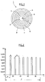
- the evolution of the gain G obtained with the amplification device described above is represented as a function of the wavelength ⁇ of the signal.
- Curve 50 shows a relatively high gain for wavelengths ⁇ less than 1520 nm, which shows the contribution of the amplification device according to the invention.
- the gain curve 50 is flat, i.e. the gain is relatively constant as a function of the wavelength. This is an inherent feature of the amplification device according to the invention, which may be advantageously used in other applications.
Landscapes
- Physics & Mathematics (AREA)
- Optics & Photonics (AREA)
- Electromagnetism (AREA)
- General Physics & Mathematics (AREA)
- Engineering & Computer Science (AREA)
- Plasma & Fusion (AREA)
- Lasers (AREA)
- Glass Compositions (AREA)
Applications Claiming Priority (2)
| Application Number | Priority Date | Filing Date | Title |
|---|---|---|---|
| FR0758946A FR2924866B1 (fr) | 2007-11-09 | 2007-11-09 | Dispositif a fibre optique dopee aux terres rares pour l'emission ou l'amplification d'un signal dans la bande "s" |
| PCT/FR2008/052018 WO2009068800A2 (fr) | 2007-11-09 | 2008-11-07 | Dispositif a fibre optique dopee aux terres rares pour l'emission ou l'amplification d'un signal dans la bande "s" |
Publications (2)
| Publication Number | Publication Date |
|---|---|
| EP2208262A2 EP2208262A2 (fr) | 2010-07-21 |
| EP2208262B1 true EP2208262B1 (fr) | 2016-06-15 |
Family
ID=39166751
Family Applications (1)
| Application Number | Title | Priority Date | Filing Date |
|---|---|---|---|
| EP08853651.1A Not-in-force EP2208262B1 (fr) | 2007-11-09 | 2008-11-07 | Dispositif a fibre optique dopee aux terres rares pour l'emission ou l'amplification d'un signal dans la bande "s" |
Country Status (6)
| Country | Link |
|---|---|
| US (1) | US8787721B2 (ja) |
| EP (1) | EP2208262B1 (ja) |
| JP (1) | JP5751833B2 (ja) |
| CN (1) | CN101855797B (ja) |
| FR (1) | FR2924866B1 (ja) |
| WO (1) | WO2009068800A2 (ja) |
Families Citing this family (6)
| Publication number | Priority date | Publication date | Assignee | Title |
|---|---|---|---|---|
| FR2939522B1 (fr) * | 2008-12-08 | 2011-02-11 | Draka Comteq France | Fibre optique amplificatrice resistante aux radiations ionisantes |
| CN109742644A (zh) * | 2019-03-11 | 2019-05-10 | 安徽天琢激光科技有限公司 | 一种高功率柱矢量光纤激光器 |
| WO2021170748A1 (en) * | 2020-02-25 | 2021-09-02 | Biolitec Unternehmensbeteiligungs Ii Ag | Preforms for speckle-free output optical fibers having structured silica sections, methods of such preform manufacture, and improved speckle-free output optical fibers |
| CN115494579A (zh) * | 2021-06-17 | 2022-12-20 | 南开大学 | 一种涡旋光宽带色散补偿光纤 |
| CN114637068B (zh) * | 2022-03-04 | 2023-12-19 | 长飞光纤光缆股份有限公司 | 一种增益均衡少模掺铒光纤及其制备方法 |
| US20240151901A1 (en) * | 2022-05-17 | 2024-05-09 | Quantinuum Llc | Waveguide with periodic index of refraction cladding |
Family Cites Families (9)
| Publication number | Priority date | Publication date | Assignee | Title |
|---|---|---|---|---|
| EP0810453B1 (en) | 1996-05-31 | 2001-10-10 | Lucent Technologies Inc. | Article comprising a micro-structured optical fiber, and method of making such fiber |
| US5802236A (en) * | 1997-02-14 | 1998-09-01 | Lucent Technologies Inc. | Article comprising a micro-structured optical fiber, and method of making such fiber |
| JP4211194B2 (ja) * | 2000-05-15 | 2009-01-21 | 住友電気工業株式会社 | 光ファイバ |
| US6606440B2 (en) * | 2000-05-15 | 2003-08-12 | Sumitomo Electric Industries, Ltd. | Microstructured optical fiber |
| US6892018B2 (en) * | 2000-11-20 | 2005-05-10 | Crystal Fibre A/S | Micro-structured optical fiber |
| EP1364237A4 (en) * | 2001-01-25 | 2006-03-22 | Omniguide Inc | LOW-LOW PHOTONIC CRYSTAL WAVE LADDER WITH GREAT CORE RADIUS |
| US6970631B2 (en) | 2002-06-05 | 2005-11-29 | Lightwave Electronics | Suppression of cladding mode loss in fiber amplifiers with distributed suppression of amplified spontaneous emission (ASE) |
| US6959022B2 (en) * | 2003-01-27 | 2005-10-25 | Ceramoptec Gmbh | Multi-clad optical fiber lasers and their manufacture |
| US7079309B1 (en) | 2003-06-25 | 2006-07-18 | Sandia Corporation | Use of a photonic crystal for optical amplifier gain control |
-
2007
- 2007-11-09 FR FR0758946A patent/FR2924866B1/fr not_active Expired - Fee Related
-
2008
- 2008-11-07 CN CN2008801151124A patent/CN101855797B/zh not_active Expired - Fee Related
- 2008-11-07 EP EP08853651.1A patent/EP2208262B1/fr not_active Not-in-force
- 2008-11-07 WO PCT/FR2008/052018 patent/WO2009068800A2/fr active Application Filing
- 2008-11-07 US US12/734,472 patent/US8787721B2/en not_active Expired - Fee Related
- 2008-11-07 JP JP2010532644A patent/JP5751833B2/ja not_active Expired - Fee Related
Also Published As
| Publication number | Publication date |
|---|---|
| US20110033162A1 (en) | 2011-02-10 |
| WO2009068800A3 (fr) | 2009-09-03 |
| JP5751833B2 (ja) | 2015-07-22 |
| US8787721B2 (en) | 2014-07-22 |
| FR2924866A1 (fr) | 2009-06-12 |
| WO2009068800A2 (fr) | 2009-06-04 |
| CN101855797A (zh) | 2010-10-06 |
| JP2011503865A (ja) | 2011-01-27 |
| EP2208262A2 (fr) | 2010-07-21 |
| CN101855797B (zh) | 2013-05-08 |
| FR2924866B1 (fr) | 2014-04-04 |
Similar Documents
| Publication | Publication Date | Title |
|---|---|---|
| EP2208262B1 (fr) | Dispositif a fibre optique dopee aux terres rares pour l'emission ou l'amplification d'un signal dans la bande "s" | |
| EP1482606B1 (fr) | Fibre optique pour amplification ou pour émission laser | |
| FR2968775A1 (fr) | Fibre optique dopee en terres rares presentant de faibles interactions entre les elements dopants | |
| US20100067860A1 (en) | Rare earth-doped core optical fiber | |
| FR2939246A1 (fr) | Fibre optique amplificatrice et procede de fabrication | |
| FR2952634A1 (fr) | Fibre en silice dopee en terre rare a faible ouverture numerique | |
| FR2968092A1 (fr) | Fibre optique dopee en terres rares insensible aux irradiations | |
| FR2939522A1 (fr) | Fibre optique amplificatrice resistante aux radiations ionisantes | |
| FR2779238A1 (fr) | Fibre optique filtrante a profil de photosensibilite modifie | |
| EP1022595A1 (fr) | Guide optique filtrant à inclinaison et à chirp linéaire | |
| FR2927476A1 (fr) | Fibre optique amplificatrice comprenant des nanoparticules et procede de fabrication | |
| EP0561672B1 (fr) | Amplificateur optique intégré et laser mettant en oeuvre un tel amplificateur | |
| EP0992817B1 (fr) | Fibre optique monomode à dispersion décalée à grande aire effective | |
| EP1121732A1 (fr) | Amplificateur laser a guide d'onde planaire | |
| FR2740563A1 (fr) | Fibre optique comprenant un dopant fluorescent | |
| FR2779239A1 (fr) | Fibre optique filtrante courte | |
| EP1455425B1 (fr) | Fibre optique amplificatrice à anneau dope et amplificateur contenant une telle fibre | |
| EP0957545B1 (fr) | Fibre optique pour amplificateur optique à gain plat | |
| EP3649707B1 (fr) | Fibre amplificatrice légèrement multimode | |
| EP1696523B1 (fr) | Amplificateur optique à diffusion raman | |
| EP2702649B1 (fr) | Fibre optique monomode à triple gaine | |
| FR2779237A1 (fr) | Guide optique filtrant a inclinaison et a chirp lineaire | |
| FR2829305A1 (fr) | Fibre optique double coeur avec anneau dope terre rare | |
| WO2001035503A1 (fr) | Laser a fibre | |
| Dai et al. | Study and manufacture of gain flattened S-band distributed dispersion compensation fiber Raman amplifier |
Legal Events
| Date | Code | Title | Description |
|---|---|---|---|
| PUAI | Public reference made under article 153(3) epc to a published international application that has entered the european phase |
Free format text: ORIGINAL CODE: 0009012 |
|
| 17P | Request for examination filed |
Effective date: 20100609 |
|
| AK | Designated contracting states |
Kind code of ref document: A2 Designated state(s): AT BE BG CH CY CZ DE DK EE ES FI FR GB GR HR HU IE IS IT LI LT LU LV MC MT NL NO PL PT RO SE SI SK TR |
|
| AX | Request for extension of the european patent |
Extension state: AL BA MK RS |
|
| DAX | Request for extension of the european patent (deleted) | ||
| RAP1 | Party data changed (applicant data changed or rights of an application transferred) |
Owner name: ALCATEL LUCENT |
|
| 111Z | Information provided on other rights and legal means of execution |
Free format text: AT BE BG CH CY CZ DE DK EE ES FI FR GB GR HR HU IE IS IT LI LT LU LV MC MT NL NO PL PT RO SE SI SK TR Effective date: 20130410 |
|
| RAP1 | Party data changed (applicant data changed or rights of an application transferred) |
Owner name: ALCATEL LUCENT |
|
| D11X | Information provided on other rights and legal means of execution (deleted) | ||
| 17Q | First examination report despatched |
Effective date: 20141118 |
|
| REG | Reference to a national code |
Ref country code: DE Ref legal event code: R079 Ref document number: 602008044745 Country of ref document: DE Free format text: PREVIOUS MAIN CLASS: H01S0003067000 Ipc: G02B0006036000 |
|
| GRAP | Despatch of communication of intention to grant a patent |
Free format text: ORIGINAL CODE: EPIDOSNIGR1 |
|
| RIC1 | Information provided on ipc code assigned before grant |
Ipc: H01S 3/067 20060101ALI20151221BHEP Ipc: H01S 3/094 20060101ALN20151221BHEP Ipc: G02B 6/036 20060101AFI20151221BHEP Ipc: H01S 3/16 20060101ALN20151221BHEP |
|
| INTG | Intention to grant announced |
Effective date: 20160122 |
|
| RIN1 | Information on inventor provided before grant (corrected) |
Inventor name: FEVRIER, SEBASTIEN Inventor name: BUROV, EKATERINA Inventor name: SIMMONNEAU, CHRISTIAN |
|
| GRAS | Grant fee paid |
Free format text: ORIGINAL CODE: EPIDOSNIGR3 |
|
| GRAA | (expected) grant |
Free format text: ORIGINAL CODE: 0009210 |
|
| AK | Designated contracting states |
Kind code of ref document: B1 Designated state(s): AT BE BG CH CY CZ DE DK EE ES FI FR GB GR HR HU IE IS IT LI LT LU LV MC MT NL NO PL PT RO SE SI SK TR |
|
| REG | Reference to a national code |
Ref country code: CH Ref legal event code: EP Ref country code: GB Ref legal event code: FG4D Free format text: NOT ENGLISH |
|
| REG | Reference to a national code |
Ref country code: IE Ref legal event code: FG4D Free format text: LANGUAGE OF EP DOCUMENT: FRENCH |
|
| REG | Reference to a national code |
Ref country code: AT Ref legal event code: REF Ref document number: 806779 Country of ref document: AT Kind code of ref document: T Effective date: 20160715 |
|
| REG | Reference to a national code |
Ref country code: DE Ref legal event code: R096 Ref document number: 602008044745 Country of ref document: DE |
|
| REG | Reference to a national code |
Ref country code: LT Ref legal event code: MG4D |
|
| REG | Reference to a national code |
Ref country code: NL Ref legal event code: MP Effective date: 20160615 |
|
| PG25 | Lapsed in a contracting state [announced via postgrant information from national office to epo] |
Ref country code: NO Free format text: LAPSE BECAUSE OF FAILURE TO SUBMIT A TRANSLATION OF THE DESCRIPTION OR TO PAY THE FEE WITHIN THE PRESCRIBED TIME-LIMIT Effective date: 20160915 Ref country code: LT Free format text: LAPSE BECAUSE OF FAILURE TO SUBMIT A TRANSLATION OF THE DESCRIPTION OR TO PAY THE FEE WITHIN THE PRESCRIBED TIME-LIMIT Effective date: 20160615 Ref country code: FI Free format text: LAPSE BECAUSE OF FAILURE TO SUBMIT A TRANSLATION OF THE DESCRIPTION OR TO PAY THE FEE WITHIN THE PRESCRIBED TIME-LIMIT Effective date: 20160615 |
|
| REG | Reference to a national code |
Ref country code: AT Ref legal event code: MK05 Ref document number: 806779 Country of ref document: AT Kind code of ref document: T Effective date: 20160615 |
|
| REG | Reference to a national code |
Ref country code: FR Ref legal event code: PLFP Year of fee payment: 9 |
|
| PG25 | Lapsed in a contracting state [announced via postgrant information from national office to epo] |
Ref country code: SE Free format text: LAPSE BECAUSE OF FAILURE TO SUBMIT A TRANSLATION OF THE DESCRIPTION OR TO PAY THE FEE WITHIN THE PRESCRIBED TIME-LIMIT Effective date: 20160615 Ref country code: LV Free format text: LAPSE BECAUSE OF FAILURE TO SUBMIT A TRANSLATION OF THE DESCRIPTION OR TO PAY THE FEE WITHIN THE PRESCRIBED TIME-LIMIT Effective date: 20160615 Ref country code: HR Free format text: LAPSE BECAUSE OF FAILURE TO SUBMIT A TRANSLATION OF THE DESCRIPTION OR TO PAY THE FEE WITHIN THE PRESCRIBED TIME-LIMIT Effective date: 20160615 Ref country code: GR Free format text: LAPSE BECAUSE OF FAILURE TO SUBMIT A TRANSLATION OF THE DESCRIPTION OR TO PAY THE FEE WITHIN THE PRESCRIBED TIME-LIMIT Effective date: 20160916 Ref country code: NL Free format text: LAPSE BECAUSE OF FAILURE TO SUBMIT A TRANSLATION OF THE DESCRIPTION OR TO PAY THE FEE WITHIN THE PRESCRIBED TIME-LIMIT Effective date: 20160615 |
|
| PG25 | Lapsed in a contracting state [announced via postgrant information from national office to epo] |
Ref country code: IT Free format text: LAPSE BECAUSE OF FAILURE TO SUBMIT A TRANSLATION OF THE DESCRIPTION OR TO PAY THE FEE WITHIN THE PRESCRIBED TIME-LIMIT Effective date: 20160615 Ref country code: RO Free format text: LAPSE BECAUSE OF FAILURE TO SUBMIT A TRANSLATION OF THE DESCRIPTION OR TO PAY THE FEE WITHIN THE PRESCRIBED TIME-LIMIT Effective date: 20160615 Ref country code: EE Free format text: LAPSE BECAUSE OF FAILURE TO SUBMIT A TRANSLATION OF THE DESCRIPTION OR TO PAY THE FEE WITHIN THE PRESCRIBED TIME-LIMIT Effective date: 20160615 Ref country code: SK Free format text: LAPSE BECAUSE OF FAILURE TO SUBMIT A TRANSLATION OF THE DESCRIPTION OR TO PAY THE FEE WITHIN THE PRESCRIBED TIME-LIMIT Effective date: 20160615 Ref country code: IS Free format text: LAPSE BECAUSE OF FAILURE TO SUBMIT A TRANSLATION OF THE DESCRIPTION OR TO PAY THE FEE WITHIN THE PRESCRIBED TIME-LIMIT Effective date: 20161015 Ref country code: CZ Free format text: LAPSE BECAUSE OF FAILURE TO SUBMIT A TRANSLATION OF THE DESCRIPTION OR TO PAY THE FEE WITHIN THE PRESCRIBED TIME-LIMIT Effective date: 20160615 |
|
| PGFP | Annual fee paid to national office [announced via postgrant information from national office to epo] |
Ref country code: FR Payment date: 20161118 Year of fee payment: 9 |
|
| PG25 | Lapsed in a contracting state [announced via postgrant information from national office to epo] |
Ref country code: ES Free format text: LAPSE BECAUSE OF FAILURE TO SUBMIT A TRANSLATION OF THE DESCRIPTION OR TO PAY THE FEE WITHIN THE PRESCRIBED TIME-LIMIT Effective date: 20160615 Ref country code: BE Free format text: LAPSE BECAUSE OF NON-PAYMENT OF DUE FEES Effective date: 20161130 Ref country code: PT Free format text: LAPSE BECAUSE OF FAILURE TO SUBMIT A TRANSLATION OF THE DESCRIPTION OR TO PAY THE FEE WITHIN THE PRESCRIBED TIME-LIMIT Effective date: 20161017 Ref country code: AT Free format text: LAPSE BECAUSE OF FAILURE TO SUBMIT A TRANSLATION OF THE DESCRIPTION OR TO PAY THE FEE WITHIN THE PRESCRIBED TIME-LIMIT Effective date: 20160615 Ref country code: PL Free format text: LAPSE BECAUSE OF FAILURE TO SUBMIT A TRANSLATION OF THE DESCRIPTION OR TO PAY THE FEE WITHIN THE PRESCRIBED TIME-LIMIT Effective date: 20160615 |
|
| REG | Reference to a national code |
Ref country code: DE Ref legal event code: R097 Ref document number: 602008044745 Country of ref document: DE |
|
| PLBE | No opposition filed within time limit |
Free format text: ORIGINAL CODE: 0009261 |
|
| STAA | Information on the status of an ep patent application or granted ep patent |
Free format text: STATUS: NO OPPOSITION FILED WITHIN TIME LIMIT |
|
| 26N | No opposition filed |
Effective date: 20170316 |
|
| PG25 | Lapsed in a contracting state [announced via postgrant information from national office to epo] |
Ref country code: DK Free format text: LAPSE BECAUSE OF FAILURE TO SUBMIT A TRANSLATION OF THE DESCRIPTION OR TO PAY THE FEE WITHIN THE PRESCRIBED TIME-LIMIT Effective date: 20160615 |
|
| REG | Reference to a national code |
Ref country code: CH Ref legal event code: PL |
|
| PG25 | Lapsed in a contracting state [announced via postgrant information from national office to epo] |
Ref country code: CH Free format text: LAPSE BECAUSE OF NON-PAYMENT OF DUE FEES Effective date: 20161130 Ref country code: LI Free format text: LAPSE BECAUSE OF NON-PAYMENT OF DUE FEES Effective date: 20161130 |
|
| REG | Reference to a national code |
Ref country code: IE Ref legal event code: MM4A |
|
| PG25 | Lapsed in a contracting state [announced via postgrant information from national office to epo] |
Ref country code: SI Free format text: LAPSE BECAUSE OF FAILURE TO SUBMIT A TRANSLATION OF THE DESCRIPTION OR TO PAY THE FEE WITHIN THE PRESCRIBED TIME-LIMIT Effective date: 20160615 |
|
| PG25 | Lapsed in a contracting state [announced via postgrant information from national office to epo] |
Ref country code: LU Free format text: LAPSE BECAUSE OF NON-PAYMENT OF DUE FEES Effective date: 20161130 |
|
| PG25 | Lapsed in a contracting state [announced via postgrant information from national office to epo] |
Ref country code: IE Free format text: LAPSE BECAUSE OF NON-PAYMENT OF DUE FEES Effective date: 20161107 |
|
| PGFP | Annual fee paid to national office [announced via postgrant information from national office to epo] |
Ref country code: DE Payment date: 20171121 Year of fee payment: 10 |
|
| REG | Reference to a national code |
Ref country code: BE Ref legal event code: MM Effective date: 20161130 |
|
| PGFP | Annual fee paid to national office [announced via postgrant information from national office to epo] |
Ref country code: GB Payment date: 20171123 Year of fee payment: 10 |
|
| PG25 | Lapsed in a contracting state [announced via postgrant information from national office to epo] |
Ref country code: HU Free format text: LAPSE BECAUSE OF FAILURE TO SUBMIT A TRANSLATION OF THE DESCRIPTION OR TO PAY THE FEE WITHIN THE PRESCRIBED TIME-LIMIT; INVALID AB INITIO Effective date: 20081107 Ref country code: CY Free format text: LAPSE BECAUSE OF FAILURE TO SUBMIT A TRANSLATION OF THE DESCRIPTION OR TO PAY THE FEE WITHIN THE PRESCRIBED TIME-LIMIT Effective date: 20160615 |
|
| PG25 | Lapsed in a contracting state [announced via postgrant information from national office to epo] |
Ref country code: MC Free format text: LAPSE BECAUSE OF FAILURE TO SUBMIT A TRANSLATION OF THE DESCRIPTION OR TO PAY THE FEE WITHIN THE PRESCRIBED TIME-LIMIT Effective date: 20160615 Ref country code: TR Free format text: LAPSE BECAUSE OF FAILURE TO SUBMIT A TRANSLATION OF THE DESCRIPTION OR TO PAY THE FEE WITHIN THE PRESCRIBED TIME-LIMIT Effective date: 20160615 |
|
| PG25 | Lapsed in a contracting state [announced via postgrant information from national office to epo] |
Ref country code: BG Free format text: LAPSE BECAUSE OF FAILURE TO SUBMIT A TRANSLATION OF THE DESCRIPTION OR TO PAY THE FEE WITHIN THE PRESCRIBED TIME-LIMIT Effective date: 20160615 |
|
| REG | Reference to a national code |
Ref country code: FR Ref legal event code: ST Effective date: 20180731 |
|
| PG25 | Lapsed in a contracting state [announced via postgrant information from national office to epo] |
Ref country code: MT Free format text: LAPSE BECAUSE OF FAILURE TO SUBMIT A TRANSLATION OF THE DESCRIPTION OR TO PAY THE FEE WITHIN THE PRESCRIBED TIME-LIMIT Effective date: 20160615 |
|
| PG25 | Lapsed in a contracting state [announced via postgrant information from national office to epo] |
Ref country code: FR Free format text: LAPSE BECAUSE OF NON-PAYMENT OF DUE FEES Effective date: 20171130 |
|
| REG | Reference to a national code |
Ref country code: DE Ref legal event code: R082 Ref document number: 602008044745 Country of ref document: DE Representative=s name: MENZIETTI WETZEL, DE Ref country code: DE Ref legal event code: R081 Ref document number: 602008044745 Country of ref document: DE Owner name: PROVENANCE ASSET GROUP LLC, PITTSFORD, US Free format text: FORMER OWNER: ALCATEL LUCENT, BOULOGNE BILLANCOURT, FR |
|
| REG | Reference to a national code |
Ref country code: GB Ref legal event code: 732E Free format text: REGISTERED BETWEEN 20190418 AND 20190426 |
|
| REG | Reference to a national code |
Ref country code: DE Ref legal event code: R119 Ref document number: 602008044745 Country of ref document: DE |
|
| GBPC | Gb: european patent ceased through non-payment of renewal fee |
Effective date: 20181107 |
|
| PG25 | Lapsed in a contracting state [announced via postgrant information from national office to epo] |
Ref country code: DE Free format text: LAPSE BECAUSE OF NON-PAYMENT OF DUE FEES Effective date: 20190601 |
|
| PG25 | Lapsed in a contracting state [announced via postgrant information from national office to epo] |
Ref country code: GB Free format text: LAPSE BECAUSE OF NON-PAYMENT OF DUE FEES Effective date: 20181107 |