EP2208118B1 - Procédé et dispositif de production d'hologrammes comprenant des régions ayant des caractéristiques de diffusion variées et l'hologramme correspondant - Google Patents
Procédé et dispositif de production d'hologrammes comprenant des régions ayant des caractéristiques de diffusion variées et l'hologramme correspondant Download PDFInfo
- Publication number
- EP2208118B1 EP2208118B1 EP08845505.0A EP08845505A EP2208118B1 EP 2208118 B1 EP2208118 B1 EP 2208118B1 EP 08845505 A EP08845505 A EP 08845505A EP 2208118 B1 EP2208118 B1 EP 2208118B1
- Authority
- EP
- European Patent Office
- Prior art keywords
- hologram
- light
- regions
- master
- recording material
- Prior art date
- Legal status (The legal status is an assumption and is not a legal conclusion. Google has not performed a legal analysis and makes no representation as to the accuracy of the status listed.)
- Not-in-force
Links
- 238000000034 method Methods 0.000 title claims description 23
- 239000000463 material Substances 0.000 claims description 58
- 230000001427 coherent effect Effects 0.000 claims description 51
- 239000000758 substrate Substances 0.000 claims description 43
- 230000005540 biological transmission Effects 0.000 claims description 17
- 238000009826 distribution Methods 0.000 claims description 15
- 238000004519 manufacturing process Methods 0.000 claims description 14
- 238000003384 imaging method Methods 0.000 claims description 8
- 230000000694 effects Effects 0.000 claims description 6
- 230000003746 surface roughness Effects 0.000 claims description 5
- 238000006073 displacement reaction Methods 0.000 claims description 2
- 230000001747 exhibiting effect Effects 0.000 claims 1
- 239000010410 layer Substances 0.000 description 17
- 238000012795 verification Methods 0.000 description 12
- 238000007639 printing Methods 0.000 description 11
- 238000005286 illumination Methods 0.000 description 10
- 238000001514 detection method Methods 0.000 description 7
- 239000005337 ground glass Substances 0.000 description 5
- 230000007423 decrease Effects 0.000 description 4
- 238000011156 evaluation Methods 0.000 description 4
- 239000000835 fiber Substances 0.000 description 4
- 238000007646 gravure printing Methods 0.000 description 4
- 239000004973 liquid crystal related substance Substances 0.000 description 4
- 229920000139 polyethylene terephthalate Polymers 0.000 description 4
- 230000003595 spectral effect Effects 0.000 description 4
- 238000013459 approach Methods 0.000 description 3
- 239000011241 protective layer Substances 0.000 description 3
- 238000004049 embossing Methods 0.000 description 2
- 238000000605 extraction Methods 0.000 description 2
- 239000004922 lacquer Substances 0.000 description 2
- 239000002650 laminated plastic Substances 0.000 description 2
- 238000013507 mapping Methods 0.000 description 2
- 238000004806 packaging method and process Methods 0.000 description 2
- 239000003973 paint Substances 0.000 description 2
- 239000004033 plastic Substances 0.000 description 2
- 229920003023 plastic Polymers 0.000 description 2
- 229920006254 polymer film Polymers 0.000 description 2
- 238000007650 screen-printing Methods 0.000 description 2
- 230000035945 sensitivity Effects 0.000 description 2
- 229910052710 silicon Inorganic materials 0.000 description 2
- 239000010703 silicon Substances 0.000 description 2
- 239000000853 adhesive Substances 0.000 description 1
- 230000001070 adhesive effect Effects 0.000 description 1
- 238000007630 basic procedure Methods 0.000 description 1
- 238000000576 coating method Methods 0.000 description 1
- 239000003086 colorant Substances 0.000 description 1
- 239000002131 composite material Substances 0.000 description 1
- 230000001419 dependent effect Effects 0.000 description 1
- 238000013461 design Methods 0.000 description 1
- 238000011161 development Methods 0.000 description 1
- 238000010586 diagram Methods 0.000 description 1
- 229940079593 drug Drugs 0.000 description 1
- 239000003814 drug Substances 0.000 description 1
- 239000011521 glass Substances 0.000 description 1
- 238000001093 holography Methods 0.000 description 1
- 230000010354 integration Effects 0.000 description 1
- 230000001678 irradiating effect Effects 0.000 description 1
- 230000002427 irreversible effect Effects 0.000 description 1
- 238000011031 large-scale manufacturing process Methods 0.000 description 1
- 230000003278 mimic effect Effects 0.000 description 1
- 238000000465 moulding Methods 0.000 description 1
- 230000003287 optical effect Effects 0.000 description 1
- 230000000149 penetrating effect Effects 0.000 description 1
- -1 polyethylene terephthalate Polymers 0.000 description 1
- 239000005020 polyethylene terephthalate Substances 0.000 description 1
- 230000035755 proliferation Effects 0.000 description 1
- 230000005855 radiation Effects 0.000 description 1
- 230000002441 reversible effect Effects 0.000 description 1
- 230000001360 synchronised effect Effects 0.000 description 1
- 238000012360 testing method Methods 0.000 description 1
- 230000007704 transition Effects 0.000 description 1
- XLYOFNOQVPJJNP-UHFFFAOYSA-N water Substances O XLYOFNOQVPJJNP-UHFFFAOYSA-N 0.000 description 1
Images


Classifications
-
- G—PHYSICS
- G03—PHOTOGRAPHY; CINEMATOGRAPHY; ANALOGOUS TECHNIQUES USING WAVES OTHER THAN OPTICAL WAVES; ELECTROGRAPHY; HOLOGRAPHY
- G03H—HOLOGRAPHIC PROCESSES OR APPARATUS
- G03H1/00—Holographic processes or apparatus using light, infrared or ultraviolet waves for obtaining holograms or for obtaining an image from them; Details peculiar thereto
- G03H1/22—Processes or apparatus for obtaining an optical image from holograms
-
- G—PHYSICS
- G03—PHOTOGRAPHY; CINEMATOGRAPHY; ANALOGOUS TECHNIQUES USING WAVES OTHER THAN OPTICAL WAVES; ELECTROGRAPHY; HOLOGRAPHY
- G03H—HOLOGRAPHIC PROCESSES OR APPARATUS
- G03H1/00—Holographic processes or apparatus using light, infrared or ultraviolet waves for obtaining holograms or for obtaining an image from them; Details peculiar thereto
- G03H1/02—Details of features involved during the holographic process; Replication of holograms without interference recording
- G03H1/0236—Form or shape of the hologram when not registered to the substrate, e.g. trimming the hologram to alphanumerical shape
-
- G—PHYSICS
- G03—PHOTOGRAPHY; CINEMATOGRAPHY; ANALOGOUS TECHNIQUES USING WAVES OTHER THAN OPTICAL WAVES; ELECTROGRAPHY; HOLOGRAPHY
- G03H—HOLOGRAPHIC PROCESSES OR APPARATUS
- G03H1/00—Holographic processes or apparatus using light, infrared or ultraviolet waves for obtaining holograms or for obtaining an image from them; Details peculiar thereto
- G03H1/04—Processes or apparatus for producing holograms
- G03H1/20—Copying holograms by holographic, i.e. optical means
- G03H1/202—Contact copy when the reconstruction beam for the master H1 also serves as reference beam for the copy H2
-
- G—PHYSICS
- G07—CHECKING-DEVICES
- G07D—HANDLING OF COINS OR VALUABLE PAPERS, e.g. TESTING, SORTING BY DENOMINATIONS, COUNTING, DISPENSING, CHANGING OR DEPOSITING
- G07D7/00—Testing specially adapted to determine the identity or genuineness of valuable papers or for segregating those which are unacceptable, e.g. banknotes that are alien to a currency
- G07D7/003—Testing specially adapted to determine the identity or genuineness of valuable papers or for segregating those which are unacceptable, e.g. banknotes that are alien to a currency using security elements
- G07D7/0032—Testing specially adapted to determine the identity or genuineness of valuable papers or for segregating those which are unacceptable, e.g. banknotes that are alien to a currency using security elements using holograms
-
- B—PERFORMING OPERATIONS; TRANSPORTING
- B42—BOOKBINDING; ALBUMS; FILES; SPECIAL PRINTED MATTER
- B42D—BOOKS; BOOK COVERS; LOOSE LEAVES; PRINTED MATTER CHARACTERISED BY IDENTIFICATION OR SECURITY FEATURES; PRINTED MATTER OF SPECIAL FORMAT OR STYLE NOT OTHERWISE PROVIDED FOR; DEVICES FOR USE THEREWITH AND NOT OTHERWISE PROVIDED FOR; MOVABLE-STRIP WRITING OR READING APPARATUS
- B42D25/00—Information-bearing cards or sheet-like structures characterised by identification or security features; Manufacture thereof
- B42D25/30—Identification or security features, e.g. for preventing forgery
- B42D25/328—Diffraction gratings; Holograms
-
- G—PHYSICS
- G03—PHOTOGRAPHY; CINEMATOGRAPHY; ANALOGOUS TECHNIQUES USING WAVES OTHER THAN OPTICAL WAVES; ELECTROGRAPHY; HOLOGRAPHY
- G03H—HOLOGRAPHIC PROCESSES OR APPARATUS
- G03H1/00—Holographic processes or apparatus using light, infrared or ultraviolet waves for obtaining holograms or for obtaining an image from them; Details peculiar thereto
- G03H1/0005—Adaptation of holography to specific applications
- G03H1/0011—Adaptation of holography to specific applications for security or authentication
-
- G—PHYSICS
- G03—PHOTOGRAPHY; CINEMATOGRAPHY; ANALOGOUS TECHNIQUES USING WAVES OTHER THAN OPTICAL WAVES; ELECTROGRAPHY; HOLOGRAPHY
- G03H—HOLOGRAPHIC PROCESSES OR APPARATUS
- G03H1/00—Holographic processes or apparatus using light, infrared or ultraviolet waves for obtaining holograms or for obtaining an image from them; Details peculiar thereto
- G03H1/02—Details of features involved during the holographic process; Replication of holograms without interference recording
- G03H1/0252—Laminate comprising a hologram layer
- G03H1/0256—Laminate comprising a hologram layer having specific functional layer
-
- G—PHYSICS
- G03—PHOTOGRAPHY; CINEMATOGRAPHY; ANALOGOUS TECHNIQUES USING WAVES OTHER THAN OPTICAL WAVES; ELECTROGRAPHY; HOLOGRAPHY
- G03H—HOLOGRAPHIC PROCESSES OR APPARATUS
- G03H1/00—Holographic processes or apparatus using light, infrared or ultraviolet waves for obtaining holograms or for obtaining an image from them; Details peculiar thereto
- G03H1/26—Processes or apparatus specially adapted to produce multiple sub- holograms or to obtain images from them, e.g. multicolour technique
- G03H1/2645—Multiplexing processes, e.g. aperture, shift, or wavefront multiplexing
- G03H1/265—Angle multiplexing; Multichannel holograms
-
- G—PHYSICS
- G03—PHOTOGRAPHY; CINEMATOGRAPHY; ANALOGOUS TECHNIQUES USING WAVES OTHER THAN OPTICAL WAVES; ELECTROGRAPHY; HOLOGRAPHY
- G03H—HOLOGRAPHIC PROCESSES OR APPARATUS
- G03H1/00—Holographic processes or apparatus using light, infrared or ultraviolet waves for obtaining holograms or for obtaining an image from them; Details peculiar thereto
- G03H1/0005—Adaptation of holography to specific applications
- G03H1/0011—Adaptation of holography to specific applications for security or authentication
- G03H2001/0016—Covert holograms or holobjects requiring additional knowledge to be perceived, e.g. holobject reconstructed only under IR illumination
-
- G—PHYSICS
- G03—PHOTOGRAPHY; CINEMATOGRAPHY; ANALOGOUS TECHNIQUES USING WAVES OTHER THAN OPTICAL WAVES; ELECTROGRAPHY; HOLOGRAPHY
- G03H—HOLOGRAPHIC PROCESSES OR APPARATUS
- G03H1/00—Holographic processes or apparatus using light, infrared or ultraviolet waves for obtaining holograms or for obtaining an image from them; Details peculiar thereto
- G03H1/04—Processes or apparatus for producing holograms
- G03H1/20—Copying holograms by holographic, i.e. optical means
- G03H2001/205—Subdivided copy, e.g. scanning transfer
-
- G—PHYSICS
- G03—PHOTOGRAPHY; CINEMATOGRAPHY; ANALOGOUS TECHNIQUES USING WAVES OTHER THAN OPTICAL WAVES; ELECTROGRAPHY; HOLOGRAPHY
- G03H—HOLOGRAPHIC PROCESSES OR APPARATUS
- G03H1/00—Holographic processes or apparatus using light, infrared or ultraviolet waves for obtaining holograms or for obtaining an image from them; Details peculiar thereto
- G03H1/22—Processes or apparatus for obtaining an optical image from holograms
- G03H1/2202—Reconstruction geometries or arrangements
- G03H2001/2223—Particular relationship between light source, hologram and observer
-
- G—PHYSICS
- G03—PHOTOGRAPHY; CINEMATOGRAPHY; ANALOGOUS TECHNIQUES USING WAVES OTHER THAN OPTICAL WAVES; ELECTROGRAPHY; HOLOGRAPHY
- G03H—HOLOGRAPHIC PROCESSES OR APPARATUS
- G03H1/00—Holographic processes or apparatus using light, infrared or ultraviolet waves for obtaining holograms or for obtaining an image from them; Details peculiar thereto
- G03H1/22—Processes or apparatus for obtaining an optical image from holograms
- G03H1/2202—Reconstruction geometries or arrangements
- G03H2001/2244—Means for detecting or recording the holobject
-
- G—PHYSICS
- G03—PHOTOGRAPHY; CINEMATOGRAPHY; ANALOGOUS TECHNIQUES USING WAVES OTHER THAN OPTICAL WAVES; ELECTROGRAPHY; HOLOGRAPHY
- G03H—HOLOGRAPHIC PROCESSES OR APPARATUS
- G03H2210/00—Object characteristics
- G03H2210/10—Modulation characteristics, e.g. amplitude, phase, polarisation
- G03H2210/11—Amplitude modulating object
-
- G—PHYSICS
- G03—PHOTOGRAPHY; CINEMATOGRAPHY; ANALOGOUS TECHNIQUES USING WAVES OTHER THAN OPTICAL WAVES; ELECTROGRAPHY; HOLOGRAPHY
- G03H—HOLOGRAPHIC PROCESSES OR APPARATUS
- G03H2210/00—Object characteristics
- G03H2210/50—Nature of the object
- G03H2210/54—For individualisation of product
-
- G—PHYSICS
- G03—PHOTOGRAPHY; CINEMATOGRAPHY; ANALOGOUS TECHNIQUES USING WAVES OTHER THAN OPTICAL WAVES; ELECTROGRAPHY; HOLOGRAPHY
- G03H—HOLOGRAPHIC PROCESSES OR APPARATUS
- G03H2222/00—Light sources or light beam properties
- G03H2222/20—Coherence of the light source
- G03H2222/24—Low coherence light normally not allowing valuable record or reconstruction
-
- G—PHYSICS
- G03—PHOTOGRAPHY; CINEMATOGRAPHY; ANALOGOUS TECHNIQUES USING WAVES OTHER THAN OPTICAL WAVES; ELECTROGRAPHY; HOLOGRAPHY
- G03H—HOLOGRAPHIC PROCESSES OR APPARATUS
- G03H2223/00—Optical components
- G03H2223/12—Amplitude mask, e.g. diaphragm, Louver filter
-
- G—PHYSICS
- G03—PHOTOGRAPHY; CINEMATOGRAPHY; ANALOGOUS TECHNIQUES USING WAVES OTHER THAN OPTICAL WAVES; ELECTROGRAPHY; HOLOGRAPHY
- G03H—HOLOGRAPHIC PROCESSES OR APPARATUS
- G03H2225/00—Active addressable light modulator
- G03H2225/10—Shape or geometry
- G03H2225/11—1D SLM
-
- G—PHYSICS
- G03—PHOTOGRAPHY; CINEMATOGRAPHY; ANALOGOUS TECHNIQUES USING WAVES OTHER THAN OPTICAL WAVES; ELECTROGRAPHY; HOLOGRAPHY
- G03H—HOLOGRAPHIC PROCESSES OR APPARATUS
- G03H2225/00—Active addressable light modulator
- G03H2225/10—Shape or geometry
- G03H2225/12—2D SLM
-
- G—PHYSICS
- G03—PHOTOGRAPHY; CINEMATOGRAPHY; ANALOGOUS TECHNIQUES USING WAVES OTHER THAN OPTICAL WAVES; ELECTROGRAPHY; HOLOGRAPHY
- G03H—HOLOGRAPHIC PROCESSES OR APPARATUS
- G03H2225/00—Active addressable light modulator
- G03H2225/30—Modulation
- G03H2225/31—Amplitude only
Definitions
- the invention relates to a method and an apparatus for producing holograms as security elements, in particular for security documents, and to a method for producing security documents, which include such holograms as security elements.
- Security documents are all documents that are to be protected against unauthorized copying and / or counterfeiting. Security documents thus include all types of identification documents, such as passports, ID cards, identity cards, driving licenses, etc., documents of value, but also, for example, packaging, for example, of medicines, etc. Security elements serve to enable authenticity checking of security documents.
- One type of security element is holograms. Security elements often include individualizing information. In the case of security elements for or from identity documents, this information includes, for example, a serial number, a card number, biometric data, pictures (passport pictures), etc.
- hologram master is produced with a master hologram. Then the hologram master is positioned behind a holographic recording material. Coherent light, for example from a laser, is irradiated onto the side of the holographic recording material facing away from the hologram master, typically with a defined wavelength and a defined angle of incidence, in accordance with the holographic pattern to be reconstructed by the hologram master.
- the hologram master can be designed so that it is sensitive to several wavelengths and this bends accordingly. Also, other than the described arrangement can be used to produce holograms.
- the coherent light can be modulated by a spatial light modulator.
- an individualization pattern is impressed on the hologram.
- digital projectors which work with Spatial Light modulators in the form of liquid crystal displays (LCD).
- the function corresponds, for example, to the projection of a slide, with the Spatial Light Modulator replacing the slide.
- DMD Digital Micro Mirror Device
- DMD Digital Micro Mirror Device
- hologram master for a customization template a hologram of a ground glass, which is also referred to as master hologram.
- the hologram has the peculiarity that in the reconstruction, that is, when the master hologram is contact-printed, which is illuminated at the reference angle (also referred to as the exposure incident angle), light is not diffracted or reflected in just one direction at an exposure failure angle but in an angular range around the exposure failure angle.
- the ground glass and thus the master hologram made by it have a scattering characteristic which is characterized by the size of the angular range in which the incident light is scattered.
- a hologram made with such a "ground glass” master hologram according to the above-described contact-copy method also has this property of being more "tolerant" to deviations from optimal reconstruction geometry.
- a typical layer thickness of a holographic recording material is about 10 ⁇ m
- it is found that such holograms are particularly suitable for use on rough substrates, for example paper substrates with a watermark, because paper has a greater roughness in the area of a watermark in the remaining areas. This is due to the process of making watermarks in paper.
- Watermarks are made by structures that are located in a sieve, with which the pulp is scooped out of the water. At locations where the screen is raised, fewer fibers accumulate than at those locations where the screen has recesses. There are more fibers collecting. At the points where there are fewer fibers, the paper is more transparent than at those points where more fibers have collected. In transmitted light, the watermark without technical aids is also easy to recognize for a layman. Modern paper mills are able to display patterns, characters and other graphic representations in different shades of gray.
- holograms Modern security documents, such as passports, packaging or software certificates of authenticity, today already include holograms as security elements. Passports and identity cards also often include a hologram, which is individualized with an individualization pattern representing the passport photo. With the proliferation of technical equipment needed to produce holograms, particularly individualized holograms, it is feared that document counterfeiters could mimic or produce simple holograms. Thus, holograms are required whose production costs for counterfeiters are increased, whereby the increased expense should lead to at least one additional feature of the hologram which is easy to verify.
- a device for the optical testing of holograms or kinegrams.
- the device has a holder for the carrier having the hologram, a camera for recording at least that on the hologram diffracted light and at least one illumination device for illuminating the hologram.
- a method for checking a hologram is known.
- at least two images of the hologram are detected from different viewing angles and properties derived therefrom are compared with references, so that an authenticity of the hologram can be determined.
- a device for generating a reflection hologram of high resolution in which a structured mirrored surface structure is exposed in a reflection hologram.
- the structure is large compared to the wavelength of the light used for recording.
- WO 03/055691 A1 is a security element made of a plastic laminate, which has a mosaic-like, at least of surface elements composite surface pattern, wherein in the surface elements a reflective boundary layer between a molding layer and a protective layer of the plastic laminate covers optically active structures, described on the structures incident light is deflected predetermined.
- One of the surface elements may have a matt structure.
- the invention is therefore based on the technical object of providing a production method and an apparatus for producing holograms as well as such holograms and security documents themselves as well as a method for producing such security documents with a hologram as a security element, in which the hologram faces
- the known holograms difficult to produce by counterfeiters and yet reliable verification and also a large-scale production of holograms, especially individualized holograms is possible.
- a security element is a structural unit comprising at least one security feature.
- a security element can be a self-contained structural unit with a security document, which may also be a value document, connected, for example, glued, can be. But it can also be an integral part of a security document.
- An example of the first is a visa sticking on a security document.
- An example of the latter is a hologram integrated into a bill or passport, for example laminated.
- a security feature is a structure that can only be produced or reproduced with (compared to simple copying) increased effort or not at all unauthorized.
- a pattern typically consists of a multiplicity of juxtaposed pattern units or pixels.
- the pattern units or pixels of a pattern are associated with one another and arranged laterally in a defined manner, typically in one or two spatial dimensions, and overall give a representation, for example a picture, a symbol, a logo, a lettering (letters, numbers, alphanumeric) or a code (eg a barcode).
- An individualization pattern is a pattern that is used for individualization.
- Such security documents typically comprise a substrate, a print layer and optionally a transparent cover layer.
- a substrate is a support structure to which the print layer is applied with information, images, patterns, and the like. Suitable materials for a substrate are all customary materials based on paper and / or plastic in question.
- a substrate is also used to mount or attach a hologram thereto as a security element.
- a Spatial Light Modulator allows a two-dimensionally spatially resolved illumination or irradiation of a mostly flat object with modulated intensity.
- This may be, for example, a DMD (Digital Micro Mirror Device) chip, an LCD (Liquid Crystal Display) transmission display or LCoS (Liquid Crystal on Silicon) display. All have in common that a multiplicity of SLM pixels is formed, wherein each SLM pixel is activatable or deactivatable independently of other SLM pixels (intermediate stages are also possible), whereby by appropriate control of the SLM pixels, patterns or images can be projected , Due to the free controllability can also readily different images or patterns in time sequence can be generated one behind the other, for example in the form of a passport photo.
- a code or pattern is individualizing if it is unique to a person or an object or a group of persons or objects from a larger total of persons or objects. For example, a code individualizing a group of persons within the total population of a country is the city of residence. An individualizing for a person code, for example, the number of the identity card or passport photo. A code individualizing a group of bills within the total amount of bills is the value. Individualizing for a banknote is the serial number. Examples of non-individualizing codes or patterns are coats of arms, seals, insignia, etc.
- a holographic recording material is a layer of a material that is photosensitive, and in which holograms can be stored by irreversible, but also reversible photochemical and / or photophysical processes by exposure.
- the term reconstruction geometry is generally understood to mean a geometry that is used to reconstruct a hologram. This is characterized by an angle of incidence of the light used for illumination and a failure angle at which the hologram is viewed. Both angles can be varied independently of each other to change a reconstruction geometry.
- An optimal reconstruction geometry is the geometry in which the hologram is optimally reconstructed.
- An exposure incidence angle is the angle at which a master hologram is exposed in a contact copying operation to optimally reconstruct it.
- the angle at which the reconstruction is optimally observed is called the exposure failure angle.
- the word component "exposure" is intended to indicate that the reconstruction occurs during the exposure of a hologram generated in the contact copying process.
- the angle at which the hologram is optimally illuminated for reconstruction is referred to as the reconstruction incident angle
- the reconstruction failure angle is referred to as the reconstruction failure angle.
- a reconstruction geometry in which the Lighting under the reconstruction angle of incidence and viewing under the reconstruction failure angle is thus the optimal reconstruction geometry.
- Angle of incidence and angles of attack used in a reconstruction but not characterizing the optimal reconstruction geometry are not referred to herein as reconstruction angle of incidence or reconstruction failure angle.
- a method for producing a hologram comprising the steps of: providing a hologram master; Placing a holographic recording material in front of the hologram master; Generating coherent light and irradiating the holographic recording material with the coherent light so that a part of the light at the hologram master in the coherent light propagation direction behind the holographic recording material is reflected back or diffracted into the holographic recording material to be coherent with the coherent light passing through the holographic recording material and thus to expose the hologram to the recording material, wherein the hologram master is provided and / or generated with at least two regions of different scattering characteristics, the monochromatic coherent light incident at a same exposure incidence angle depending on their scattering characteristic in different sized limited angular ranges by the same exposure failure angle reflect and / or bow.
- the provision of the hologram master comprises producing a master hologram comprising the following steps: providing a carrier, producing at least two regions of different surface roughness, so that the carrier, when irradiated with light, diffuses it differently in the at least two different regions; Mapping the at least two regions Carrier is formed in a transmission hologram, reconstructing the transmission hologram and exposing the reconstruction image in a volume reflection hologram, which is the hologram master. These scattering characteristics of the two regions of the hologram master are transferred to the hologram produced. This therefore has at least two regions which differ from each other in terms of their angular dependence or angular tolerance with respect to optimal reconstruction, but can be optimally reconstructed under the same reconstruction geometry (the optimal reconstruction geometry).
- An apparatus for producing such a hologram comprises a hologram master, a recording and / or guide for a holographic recording material and a light source emitting coherent light, and imaging optics for guiding the coherent light to irradiate the holographic recording material with the coherent light, such that at least a portion of the coherent light is diffracted and / or reflected at the hologram master to interfere with the coherent light radiating through the holographic recording material in the holographic recording material, the hologram master comprising at least two regions of different scattering characteristics, each at a same exposure angle of incidence incident coherent light depending on their Streu characterizing in different sized limited standingsungsfallfallwinkel Gebe reflectively by the same Existungsausfallwinkel bend, the hologr ammmaster is a master hologram formed as a volume reflection hologram made by a method comprising the steps of: providing a carrier, producing at least two regions of different surface roughness so that the substrate, when irradiated with light, will be in the at least two
- a security document according to the invention comprises a hologram according to the invention. It is made by a method comprising the steps of making a hologram and additionally comprising the step of mounting or applying the hologram to a substrate, ie, integrating the hologram into the security document. Although high wavelength selectivity is maintained, the resulting hologram has different reconstruction geometries giving different results.
- Verification is thus performed according to a method comprising the steps of: detecting a reconstruction of the hologram among at least two predetermined reconstruction geometries adapted to the angular ranges of the scattering characteristics of the at least two regions, and evaluating differences of the detected reconstructions and comparing the differences with predetermined differences Making a verification decision based on the comparison result and issuing the verification decision.
- Adapted to the angular ranges of the scattering characteristics means that the angles defining the given reconstruction geometries are selected in such a way that clear differences in the reconstructions, which are based on the different scattering characteristics or Angular ranges of at least two regions are due.
- An apparatus for automated verification of such a hologram or security document with such a hologram therefore comprises at least one light source that generates light of the wavelength with which the hologram is exposed, and a detection device for detecting a reconstruction of the hologram, wherein a lighting and detection under at least two different predetermined reconstruction geometries can be executed, and the detection device is coupled to an evaluation unit, which compares differences of the reconstructions with predetermined expected differences and comprises an output device for outputting the comparison result. While both regions are reconstructed under the optimal reconstruction geometry, there exists at least one reconstruction geometry under which only one more strongly scattering of the at least two regions is reconstructed, ie, perceptible. However, the verification can also be carried out in a simple manner by control personnel.
- a hologram according to the invention can be made much easier.
- monochromatic light of this wavelength In order to be able to use a simple master hologram, which is selective for only one wavelength and with which a higher diffraction efficiency can be achieved, it is also advantageous to use monochromatic light of this wavelength. In a preferred embodiment it is therefore provided that the light is monochromatically generated or monochromatized.
- the device for producing the light source comprises a laser which generates monochromatic light.
- a monochromator may be provided.
- the person skilled in various devices for monochromatization of coherent light are known.
- Other embodiments provide that the hologram master reflects and / or diffracts light of different wavelengths, ie colors.
- an illuminated with different wavelengths master hologram can be used. It can thus be provided that the coherent light is generated at the same time or with a time delay with several different wavelengths
- the coherent light is locally modulated according to an individualization pattern prior to the radiation of the holographic recording material.
- the modulation of the light is done with a Spatial Light Modulator.
- Spatial Light modulators are in particular Liquid Crystal on Silicon, DMDs and LCD displays are considered.
- the individualization pattern is preferably chosen such that it extends at least partially over the at least two regions.
- the security feature given by the individualization pattern is associated with the watermarking effect of the hologram of the invention.
- the regions of the master hologram are designed in such a way that the intensity distributions of the scattered light are not constant over the angular ranges defining the scattering characteristics of the at least two regions.
- a scattering intensity at the exposure failure angle corresponding to the optimum reconstruction failure angle is maximum and steadily decreases with increasing angular deviation therefrom. Since this property of a hologram master translates to the generated hologram, it is thus easily possible for a viewer to determine whether he is viewing the hologram under the optimal reconstruction geometry. If the at least two reconstructed regions have maximum brightness, the optimal reconstruction geometry is maintained.
- a variation of the reconstruction geometry leads to a decrease in intensity (decrease in brightness) in one of the at least two regions, this indicates that the optimal reconstruction geometry is no longer satisfied.
- the scattering characteristics of the at least two regions are chosen very differently.
- a first region represents a holographic mirror that scatters light only in a very small angular range around the optimum exposure-loss angle (or reconstruction-failure angle (for a completed hologram)).
- At least one second region has a relatively high variance.
- the scattering intensity distributions are now preferably chosen such that the scattering intensities continuously increase from zero at a maximum deviation from the exposure failure angle (reconstruction failure angle (in the case of a finished hologram)) to a maximum intensity over the respective associated angular range and the maximum intensities of the at least two different regions increase depending on a size of the associated angle range differ.
- a maximum scattering intensity under the exposure failure angle (the optimal reconstruction failure angle (for a finished hologram)) preferably decreases as the angular range into which the region scatters increases. Such a behavior arises, for example, if the scatter intensities integrated in the at least two regions over the corresponding angular ranges are the same.
- the resulting holograms now point to the reconstruction depending on the deviation from an optimal reconstruction geometry, a contrast reversal of the two regions. If the deviation from the optimal reconstruction geometry is large, then only the more scattering region of the at least two regions is reconstructed "weakly". If one approximates something to the optimal reconstruction geometry, a brightness of the reconstruction of the more scattering region of the at least two regions increases. The weaker scattering region of at least two regions is not yet visible. With an even closer approach to the optimal reconstruction geometry, the brightness of the reconstruction of the more scattering region continues to increase and the reconstruction of the weaker scattering region begins. First, however, the brightness of the more scattering region is greater than that of the weaker scattering region.
- the optimal reconstruction geometry achieves an excellent geometric position, where the brightness of the weaker scattering region reaches the brightness of the more scattering region. In this excellent position, both regions are equally bright and perceptible to a viewer as a united region.
- the weaker stray region is perceived to be brighter, although a brightness of the more scattering region is also maximal in this geometry.
- the excellent reconstruction geometry is exceeded, there is a change in contrast between the more scattering region and the weaker scattering region of at least two regions.
- the more scattered region is brighter than the weaker scattering region for deviations larger than the excellent reconstruction geometry.
- the weaker scattering region is brighter than the more scattering region.
- the scattering characteristics of the hologram master are designed such that the intensity distributions of the at least two regions have an identical intensity at an (identical) excellent angle.
- a surface roughness of the carrier can be achieved, for example, by applying a preferably transparent lacquer or more preferably transparent lacquers having a different roughness.
- the paint is preferably applied by printing, for example through-printing (screen printing), high-pressure (letterpress, letter set), gravure printing (gravure printing, intaglio printing), planographic printing (offset, wet offset, dry offset), digital printing (inkjet).
- Areas of different roughness can also be achieved, for example, by recesses in the printing.
- a scattering film may be used which includes recesses or punches. This is applied to the carrier.
- the images are made in the transmission hologram and the master hologram formed as a volume reflection hologram such that the exposure incidence angle is in the range between 25 ° and 75 °, more preferably in the range between 40 ° and 50 °, and most preferably 45 °, and an exposure failure angle in Range between 80 ° and 135 °, more preferably between 80 ° and 100 °, and most preferably 90 °, wherein the angles are measured in each case against the surface of the hologram.
- a transition region is arranged between the at least two regions whose scattering characteristic, depending on a position between the at least two regions, continuously changes from the scattering characteristic of one of the at least two regions into the scattering characteristic of the other of the at least two regions.
- a hologram in a security document that includes a rough substrate. If a hologram having at least two regions of different scattering characteristics is used on a substrate which is rough, the scattering characteristic of the weaker scattering region is preferably at least large enough for the hologram to be completely reconstructed under the optimal reconstruction geometry.
- a security document comprising a substrate having a roughness on which the hologram is mounted, wherein the hologram is made to provide the hologram master such that a weaker scattering region of the at least two regions are adapted to the roughness of the substrate so that an associated angular range is at least so great that reconstructing the entire hologram under reconstruction of the hologram mounted on the substrate under optimal reconstruction geometry.
- the angular range of the weaker scattering region is larger than an angular range of a scattering characteristic necessary for compensating the roughness of the substrate.
- the reconstruction behavior of that region changes due to the roughness of the substrate locally surrounding the hologram affected.
- the hologram only reconstructs in some places, but not in others. Due to the local "deformation" of the hologram due to the roughness of the substrate, the light strikes at only a few locations below the reconstruction angle of incidence. In the remaining places, the light hits at a different angle, so that no reconstruction takes place. The greater the roughness of the substrate in the region, the larger area fractions do not "reconstruct" when viewed under the reconstruction failure angle.
- a scattering characteristic of a region of a hologram is considered to be adapted to a roughness of a substrate when the hologram deposited on the substrate is completely reconstructed under consideration of the reconstruction failure angle despite the "deformation" due to the roughness, if it is with light below the reconstruction incident angle is illuminated. If a homogeneous hologram with a uniform scattering characteristic is applied to the substrate of uniform roughness and if the scattering characteristic is optimally adapted to the roughness, then no or only a much weaker intensity dependence of this deviation can be observed if the reconstruction geometry deviates from the optimal reconstruction geometry a use of the hologram on a smooth substrate.
- the scattering characteristic of a region of the hologram is designed such that its associated angular range is greater than the angular range necessary to compensate for the roughness of the substrate (in the case of a hologram formed as an ideal mirror), then deviating from the optimal reconstruction geometry again observe an intensity dependence.
- the at least two regions of the hologram master are now preferably selected and configured such that a more scattering region of the at least two regions is or is geometrically adapted to the region of greater roughness, for example the region of the at least one watermark, such that the hologram on the Substrate can be mounted so that the more scattering region covers the area of greater roughness (area of at least one watermark), preferably covers congruent, and scatters the scattering characteristic of the more scattering region in a larger angular range than this by the substrate in the region of the larger Roughness (area of the watermark) would be caused.
- a change in intensity as a function of a deviation from the optimal reconstruction energy is also observable in the region of the watermark.
- the remainder of the at least two regions are weaker than the more scattered region of at least two regions.
- the weaker scattering region of the hologram or hologram master has a scattering characteristic adapted to the roughness of the substrate in the area of greater roughness (area of the at least one watermark), or more preferably to the roughness of the substrate in the area of lower roughness (area outside the at least one watermark) adapted roughness. Even with a hologram produced in this way, a contrast reversal can be observed when approaching the optimal reconstruction geometry.
- the weaker scattering region located above the lower roughness area of the substrate is observable only at a closer approximation to the optimal reconstruction geometry than the more scattering region of the hologram, which is over the more scattering area of the substrate (over the watermark).
- the hologram or the security document is reconstructed under different reconstruction geometries and an evaluation unit is designed to determine the contrast reversal as a verification feature.
- the hologram is illuminated at different illumination angles and viewed at the reconstruction failure angle.
- the verification device has several light sources for this purpose.
- the hologram can be illuminated at the reconstruction angle of incidence and for reconstruction to be detected at different angles by the detection unit.
- the plurality of light sources are preferably formed as white LEDs, which generate and emit, inter alia, light of the wavelength with which the hologram was recorded.
- LEDs can be used that produce light of precisely this wavelength.
- the at least one light source can be arranged to be pivotable, so that an illumination angle can be varied. It is also possible to provide an optics which can direct the light of the at least one light source under different illumination angles to the hologram.
- the verification device is designed in such a way that the hologram can be detected under an excellent reconstruction geometry in which reconstructions of the at least two regions have approximately the same brightness, ie a scatter intensity is almost the same.
- the hologram is preferably produced, arranged or mounted on a substrate and optionally laminated with further layers to form a document body.
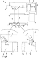
- the hologram master 2 is a holographically fabricated structure created by holographic imaging of a ground glass, as explained in greater detail below.
- the device 1 further includes a light source 5 capable of generating coherent light 8. This can be in the visible, ultraviolet or infrared spectral range.
- the light source 5 may include, for example, a laser 6, which generates coherent and usually momochromatic light.
- the light source 5 may comprise a monochromator 7 which monochromatizes the coherent light when, for example, another light generating unit is used instead of the laser 6 or the laser 6 produces light of several wavelengths.
- the coherent light 8 is preferably provided by the light source 5 as a stripe-shaped light beam.
- the light beam is extended transversely to the propagation direction along a spatial dimension.
- This extension preferably corresponds to at least one width of the hologram to be produced.
- the coherent light 8 is stretched perpendicular to the plane of the strip.
- the device 1 further comprises an imaging optics, which is shown here in simplified form as a deflection mirror 9.
- the imaging optics are designed such that the coherent light 8 is passed through a spatial light modulator 10 in which it is spatially modulated. This means that different positions along the strip-shaped extension of the coherent light 8 modulate differently across the propagation direction become. Likewise, the modulation is dependent on a lateral position at which the light passes through the spatial light modulator. The modulation takes place according to an individualization pattern for the hologram.
- the modulated coherent light beam 11 passes through the holographic recording material 4 and is at least partially diffracted and / or reflected by the hologram master 2.
- the reflected and / or diffracted light interferes with the light 11 penetrating the holographic recording material, thus exposing the hologram to the holographic recording material 4.
- a control unit 12 of the device 1 is designed to control a relative movement of the coherent light 8 or modulated coherent light 11 on the one hand and the holographic recording material 4 and the hologram master 2 on the other hand.
- the control unit 12 is connected to a drive unit 13. This is in the illustrated embodiment so with the imaging optics, i. coupled to the deflection mirror 9, that synchronized by a displacement of the deflection mirror of the Spatial Light modulator 10 and the hologram master 2 are scanned in strips.
- the control unit 12 is further configured such that an exposure time in the holographic recording material is adjusted in each case adapted to a spectral sensitivity of the holographic recording material 4 and to the wavelength of the coherent light 8, 11 used in each case for the exposure of the hologram.
- the required exposure time depends on the intensity of the coherent light and the spectral sensitivity of the holographic recording material 4.
- the control unit 12 can control either an intensity of the light source and / or a relative speed and / or an exposure time in a position of the holographic recording material 4.
- the exposure may be carried out in a so-called step-and-repeat method or continuously, for example in a drum exposure method.
- the hologram master is incorporated into a drum on which the holographic recording material rests. During the exposure, the drum rotates.
- a step-and-repeat method the area to be exposed of the film-formed holographic recording material is placed on the master and comes to rest there. This is followed by an exposure, for example, scanning or full surface, which makes the contact copy of the hologram.
- this laser beams are personalized or personalized.
- the holographic recording material formed as a film is transported on until the next unexposed area on the hologram master comes to rest.
- the hologram master 2 is illuminated in the illustrated example at an exposure angle 14 of 90 ° from the modulated coherent light 11 which has transmitted the holographic recording material.
- the hologram master 2 in the illustrated embodiment comprises a weaker scattering region 15 and a more scattering region 16. In both regions 15, 16 the light is reflected and / or diffracted into different angular ranges 17, 18 by the same exposure failure angle 19 of 45 °.
- the angular region of the more scattering region 16 includes angles of 45 ° ⁇ 20 ° and the weaker or less scattering region 15 comprises angles of 45 ° ⁇ 10 °.
- the intensities observed at the various angles depend on the particular angle. Both regions 15, 16 have an intensity distribution which starts at zero at a maximum deviation from the exposure failure angle 19, ie at 25 ° or 65 ° for the more scattering region 16 and at 35 ° or 55 ° for the weaker scattering region at zero and / or ends. The more one approaches the exposure failure angle 19, the greater the intensity in both intensity distributions. These each reach an intensity maximum at the exposure failure angle 19.
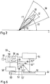
- FIG Fig. 2 is a polar diagram
- the intensity is given by a distance from the origin the angle is measured against the x-axis in the mathematically positive sense. It can be seen that the two intensity distributions have the same intensity at an excellent angle 22. At this angle, the reconstructions of the weaker scattering region 15 and the more scattering region 16 are equally intense or equally bright.
- the angle dependencies of the hologram master 2 explained here are transferred to the hologram exposed in the holographic recording material 4. The finished hologram is then preferably integrated into a security document.
- a security document with a hologram will be described below with reference to FIG Fig. 4a to 4d described in more detail.
- a flat transparent support 30 which may be formed for example as a polished glass plate
- different transparent coatings are applied, which form a corresponding layer 31 with a lower roughness and a layer 32 with a greater roughness (see. Fig. 3a ).
- the paint is preferably applied by printing, for example through-printing (screen printing), high-pressure (letterpress, letter set), gravure printing (gravure printing, intaglio printing), planographic printing (offset, wet offset, dry offset), digital printing (inkjet).
- the carrier 30 with the layers 31, 32 represents a ground glass.
- the carrier 30 and the layers 31, 32 are then irradiated by coherent monochromatic light 34 of the wavelength which is adapted to the wavelength with which the hologram (cf. Fig.
- the holographic recording material 38 having a coherent reference light 39 so as to form a transmission hologram 40.
- This transmission hologram 40 becomes, as in Fig. 3b is reconstructed with coherent light 41 and further brought to this coherent reference light 42 in another recording material 43 to interference, so that the reconstruction of the transmission hologram 40 is exposed in the further holographic recording material 43 as a volume reflection hologram, which is used as hologram master 2 in the Device 1 according to Fig. 1 can be used. If the hologram master 2 is to be reconstructed for different wavelengths, then the process described must be carried out analogously with these wavelengths.
- Fig. 4a to 4d For example, four views of a security document 44 are shown below four different reconstruction geometries for a circular hologram 45.
- the four reconstruction geometries correspond to four different tilts of the security document 44 relative to a viewing direction and a direction of illumination.
- the hologram 45 includes a more scattering region 46 surrounding a cross-shaped weaker scattering region 47.
- the reconstruction geometry, with the view Fig. 4a corresponds most strongly with an optimal reconstruction geometry, whose corresponding view in Fig. 4d is shown.
- the Fig. 4b and 4c show views of the security document 44 and the hologram 45 for reconstruction geometries which approximates stepwise the optimal reconstruction geometry. Under the reconstruction geometry which deviates strongly from the optimal reconstruction geometry (cf. Fig.
- FIGS. 4a, 4b and 4d a view is shown, which corresponds to the excellent reconstruction geometry, in which both regions are perceived as bright (equal intensity). Opposite to the view Fig. 4b Both regions are brighter. In this position is also an individualization pattern, which is symbolized here by two circles 49, which could represent, for example, eyes of a passport photograph, well recognize and capture. A comparison with the others FIGS. 4a, 4b and 4d shows that this is not or not optimally possible among the other reconstruction geometries.
- Fig. 4d Finally, there is a view taken in the optimal reconstruction geometry.
- the two regions 46, 47 have both gained in brightness once again, but the weaker scattering region 47 is stronger than the more scattered region 46.
- Contrary to opinion Fig. 4a and 4b a contrast reversal has taken place, which can be used to verify the authenticity of the hologram 45 and / or the security document 44.
- FIG. 12 is a view of another security document 44 'on which a full face hologram 45' is mounted.
- the substrate of the security document 44 'on which the hologram 45' is mounted is a paper substrate comprising watermarks in three circular areas 48, 48 ', 48'. In these areas 48, 48 ', 48 ", roughness of the substrate is increased ,
- the hologram has circular, more scattering regions 46 ', 46 "and 46''', which preferably cover the circular areas in a congruent manner.
- 46 "and 46"' is greater than a range of scattering angles which the roughness of the paper substrate would cause in the regions 48, 48', 48 "of the watermarks
- Areas 48, 48 ', 48 "covered have a scattering characteristic that is matched to the roughness of the substrate outside of the circular areas 48, 48', 48", which means that an angular range in the weaker scattering region 47 'will contribute light the reconstruction scatters, or may come from the light at the reconstruction angle of incidence for a reconstruction, greater than o which is equal to an angular range of scattering caused by the roughness of the paper substrate outside the circular area 48, 48 ', 48 ".
- the angular range of the weaker scattering region 47 ' may also be greater than an angular range of scattering caused by the roughness in the regions 48, 48', 48 "However, in any case, the angular range of the scattering characteristic of the weaker scattering region 47 is smaller than that of the more scattering regions 46 ', 46 "and 46"'.
- a contrast inversion effect is maintained as the reconstruction geometry approaches the optimal reconstruction geometry.
- Fig. 5b is a view in the excellent reconstruction geometry shown, in which both regions are perceived as bright.
- Fig. 5c the view is shown at the optimal reconstruction geometry, where the weaker scattering region 47 'is brighter than the more scattering regions 46', 46 "and 46"'. Good to see is the contrast reversal that has taken place.
- the device 50 for verification comprises at least one, but preferably a plurality of light sources 53, 53 ', 53 ", 53''', ... which emit light of the wavelength with which the hologram 51 was generated in a time-shifted manner, the light sources 53, 53 ', 53 ", 53"', ... are arranged relative to the hologram 51 so that the hologram is illuminated at different angles.
- a detection unit 54 which is formed for example as a camera or CCD and the hologram 52 viewed at the reconstruction failure angle, the optimal viewing angle, the reconstructions of the hologram 51 are detected spatially resolved and brightness resolved.
- a control 55 controls both the multiple light sources 53, 53 ', 53 ", 53"',... And the detection unit 54. Furthermore, the control unit comprises an evaluation unit 56 which evaluates changes in the detected reconstructions of the hologram 51.
- Each of the multiple light sources is linked to a reconstruction geometry. By suitable control of the multiple light sources 53, 53 ', 53 ", 53'", ..., a contrast reversal can thus be determined by a comparison unit 58.
- the individualization pattern can be extracted by an extraction unit 57 and adjusted, if necessary, with information that is stored, for example, in a chip 60 integrated in the security document and can be detected via a further detection unit 59, which is embodied, for example, as a chip card reader. Via an output unit 61, a result of the verification is output.
Claims (13)
- Procédé de production d'un hologramme (45, 45', 51) comprenant les étapes de :mise à disposition d'un hologramme maître (2),agencement d'un matériau d'enregistrement holographique (4) devant l'hologramme maître (2) ;génération de lumière cohérente (8, 11) et irradiation du matériau d'enregistrement holographique (4) avec la lumière cohérente (8, 11), de sorte qu'une partie de la lumière au niveau de l'hologramme maître (2) agencé dans le sens de propagation de la lumière cohérente (8, 11) derrière le matériau d'enregistrement holographique (4) est rétroréfléchie ou diffractée dans le matériau d'enregistrement holographique (4) pour interférer avec la lumière cohérente (8, 11) irradiant le matériau d'enregistrement holographique (4) et exposer ainsi l'hologramme (45, 45', 51) dans le matériau d'enregistrement (4), dans lequel l'hologramme maître (2) est mis à disposition avec au moins deux régions (15, 16) à caractéristiques de diffusion différentes, qui réfléchissent et/ou diffractent de la lumière cohérente incidente respectivement selon un angle d'incidence d'exposition (14) identique en fonction de leurs caractéristiques de diffusion dans des plages angulaires limitées de taille différente (17, 18) du même angle de projection d'exposition (19), dans lequel la mise à disposition de l'hologramme maître (2) comprend une production de l'hologramme maître, laquelle comprend les étapes suivantes :mise à disposition d'un support (30),génération d'au moins deux régions (31, 32) à rugosité de surface différente, de sorte que lors de l'irradiation avec de la lumière (34), le support (30) diffuse celle-ci différemment dans les au moins deux régions différentes ;représentation du support (30) présentant les au moins deux régions dans un hologramme de transmission (40),reconstruction de l'hologramme de transmission (40) et exposition de l'image de reconstruction dans l'hologramme maître (43), de sorte que celle-ci soit réalisée en tant qu'hologramme de réflexion volumique.
- Procédé selon la revendication 1, caractérisé en ce que la lumière cohérente (8) est modulée localement selon un modèle d'individualisation avant l'irradiation du matériau d'enregistrement holographique (4) pour réaliser l'hologramme (45, 45', 51) unique dans un groupe d'hologrammes produits.
- Procédé selon la revendication 1 ou 2, caractérisé en ce que l'hologramme maître (2) est mis à disposition de telle sorte que des distributions d'intensité de la lumière diffusée sur les plages angulaires (17, 18) définissant les caractéristiques de diffusion des au moins deux régions (15, 16) ne sont pas constantes.
- Procédé selon l'une quelconque des revendications 1 à 3, caractérisé en ce que les caractéristiques de diffusion de l'hologramme maître (2) sont sélectionnées de sorte que les distributions d'intensité (20, 21) des au moins deux régions (15, 16) sous un angle (22) distinct identique présentent une intensité identique.
- Procédé selon l'une quelconque des revendications 1 à 4, caractérisé en ce que l'angle d'incidence d'exposition (14) est dans la plage entre 25° et 75°, de préférence dans la plage entre 40° et 50° et s'élève de manière tout particulièrement préférée à 45° et un angle de projection d'exposition (19) est dans la plage entre 80° et 135°, de préférence dans la plage entre 80° et 100° et s'élève de manière tout particulièrement préférée à 90°.
- Hologramme (45, 45', 51), produit selon le procédé selon l'une quelconque des revendications 1 à 5.
- Procédé de production d'un document de sécurité (44, 44'), dans lequel un hologramme (45, 45', 51) est appliqué en tant qu'élément de sécurité sur un substrat, dans lequel l'hologramme (45, 45', 51) est produit selon l'une quelconque des revendications 1 à 5.
- Document de sécurité (44, 44') avec un hologramme (45, 45', 51), produit selon le procédé selon l'une quelconque des revendications 1 à 5.
- Procédé (1) de production d'un hologramme (45, 45', 51) en tant que caractéristique de sécurité d'un document de sécurité, comprenant un hologramme maître (2), une réception et/ou un guidage pour un matériau d'enregistrement holographique (4) et une source de lumière (5), qui émet de la lumière cohérente (8, 11), ainsi qu'une optique de représentation pour le guidage de la lumière cohérente (8, 11) pour irradier le matériau d'enregistrement holographique (4) avec la lumière cohérente (8, 11), de sorte qu'au moins une partie de la lumière cohérente (8, 11) au niveau de l'hologramme maître (2) est diffractée et/ou réfléchie pour interférer dans le matériau d'enregistrement holographique (4) avec la lumière cohérente (8, 11) irradiant le matériau d'enregistrement holographique (4),
caractérisé en ce que l'hologramme maître (2) comprend au moins deux régions (15, 16) à caractéristiques de diffusion différentes, qui diffractent de manière réfléchissante de la lumière cohérente monochromatique (8, 11) incidente respectivement sous un angle d'incidence d'exposition (14) identique en fonction de leurs caractéristiques de diffusion dans des plages angulaires limitées de taille différente (17, 18) du même angle de projection d'exposition (19) et l'hologramme maître (2) est un hologramme maître réalisé en tant qu'hologramme de réflexion volumique, qui est produit au moyen d'un procédé, qui comprend les étapes suivantes :mise à disposition d'un support (30),génération d'au moins deux régions (31, 32) à rugosité de surface différente, de sorte que lors de l'irradiation avec de la lumière (34), le support (30) diffuse celle-ci différemment dans les au moins deux régions différentes ;représentation du support (30) présentant les au moins deux régions en un hologramme de transmission (40),reconstruction de l'hologramme de transmission (40) et exposition de l'image de reconstruction dans l'hologramme maître, de sorte que celle-ci soit réalisée en tant qu'hologramme de réflexion volumique. - Dispositif (1) selon la revendication 9, caractérisé en ce qu'un Spatial Light Modulator (10) est agencé de telle sorte que la lumière cohérente (8) est modulable localement selon un modèle d'individualisation avant l'irradiation du matériau d'enregistrement holographique (4) pour réaliser l'hologramme (45, 45', 51) produit unique dans un groupe d'hologrammes produits.
- Dispositif selon la revendication 9 ou 10, caractérisé en ce que la lumière cohérente est générée en même temps ou de manière décalée dans le temps avec plusieurs longueurs d'onde différentes.
- Dispositif (1) selon l'une quelconque des revendications 6 à 8, caractérisé en ce que l'hologramme maître (2) est réalisé de sorte que des distributions d'intensité (20, 21) de la lumière diffusée sur les plages angulaires (17, 18) définissant les caractéristiques de diffusion des au moins deux régions (15, 16) ne sont pas constantes.
- Dispositif (1) selon l'une quelconque des revendications 9 à 12, caractérisé en ce que les caractéristiques de diffusion de l'hologramme maître (29) sont réalisées de telle sorte que les distributions d'intensité (20, 21) des au moins deux régions (15, 16) sous un angle (22) distinct identique présentent une intensité identique.
Priority Applications (1)
| Application Number | Priority Date | Filing Date | Title |
|---|---|---|---|
| EP16181035.3A EP3112948B1 (fr) | 2007-10-31 | 2008-10-31 | Procede et dispositif de verification d'hologrammes comprenant une structure similaire à un filigrane |
Applications Claiming Priority (2)
| Application Number | Priority Date | Filing Date | Title |
|---|---|---|---|
| DE102007052952A DE102007052952A1 (de) | 2007-10-31 | 2007-10-31 | Verfahren und Vorrichtung zur Herstellung von Hologrammen mit wasserzeichenartiger Struktur |
| PCT/EP2008/009347 WO2009056357A2 (fr) | 2007-10-31 | 2008-10-31 | Procédé et dispositif de production d'hologrammes à structure de type filigranée |
Related Child Applications (2)
| Application Number | Title | Priority Date | Filing Date |
|---|---|---|---|
| EP16181035.3A Division EP3112948B1 (fr) | 2007-10-31 | 2008-10-31 | Procede et dispositif de verification d'hologrammes comprenant une structure similaire à un filigrane |
| EP16181035.3A Division-Into EP3112948B1 (fr) | 2007-10-31 | 2008-10-31 | Procede et dispositif de verification d'hologrammes comprenant une structure similaire à un filigrane |
Publications (2)
| Publication Number | Publication Date |
|---|---|
| EP2208118A2 EP2208118A2 (fr) | 2010-07-21 |
| EP2208118B1 true EP2208118B1 (fr) | 2018-12-12 |
Family
ID=40303712
Family Applications (2)
| Application Number | Title | Priority Date | Filing Date |
|---|---|---|---|
| EP16181035.3A Active EP3112948B1 (fr) | 2007-10-31 | 2008-10-31 | Procede et dispositif de verification d'hologrammes comprenant une structure similaire à un filigrane |
| EP08845505.0A Not-in-force EP2208118B1 (fr) | 2007-10-31 | 2008-10-31 | Procédé et dispositif de production d'hologrammes comprenant des régions ayant des caractéristiques de diffusion variées et l'hologramme correspondant |
Family Applications Before (1)
| Application Number | Title | Priority Date | Filing Date |
|---|---|---|---|
| EP16181035.3A Active EP3112948B1 (fr) | 2007-10-31 | 2008-10-31 | Procede et dispositif de verification d'hologrammes comprenant une structure similaire à un filigrane |
Country Status (4)
| Country | Link |
|---|---|
| EP (2) | EP3112948B1 (fr) |
| JP (1) | JP5635408B2 (fr) |
| DE (1) | DE102007052952A1 (fr) |
| WO (1) | WO2009056357A2 (fr) |
Families Citing this family (14)
| Publication number | Priority date | Publication date | Assignee | Title |
|---|---|---|---|---|
| JP2010266647A (ja) * | 2009-05-14 | 2010-11-25 | Sony Corp | ホログラム判定装置 |
| CN102418302B (zh) * | 2011-10-21 | 2013-10-09 | 苏州大学 | 一种光学隐形水印安全纸 |
| JP6015168B2 (ja) * | 2012-07-03 | 2016-10-26 | 大日本印刷株式会社 | カラーシフト材を用いた真贋判定方法およびカラーシフト材 |
| DE102013200980B4 (de) * | 2013-01-22 | 2021-11-18 | Bundesdruckerei Gmbh | Verfahren zur nachträglichen holografischen Beschriftung sowie Vorrichtung zur nachträglichen holografischen Beschriftung |
| DE102013103522A1 (de) * | 2013-04-09 | 2014-10-09 | Bundesdruckerei Gmbh | Bildaufnahmesystem zur Bildaufnahme eines Merkmals eines Identifikationsdokumentes |
| DE102013103527A1 (de) * | 2013-04-09 | 2014-10-09 | Bundesdruckerei Gmbh | Bildaufnahmesystem zur Bildaufnahme von Merkmalen eines Identifikationsdokumentes |
| DE102015100513A1 (de) | 2015-01-14 | 2016-07-14 | Leonhard Kurz Stiftung & Co. Kg | Verfahren und Master zum Herstellen eines Volumenhologramms |
| RU2722335C1 (ru) * | 2019-07-29 | 2020-05-29 | Федеральное государственное бюджетное учреждение науки Институт автоматики и электрометрии Сибирского отделения Российской академии наук (ИАиЭ СО РАН) | Способ определения подлинности и качества изготовления защитных голограмм, выполненных на основе дифракционных микроструктур, и устройство для его реализации |
| DE102019121821A1 (de) * | 2019-08-13 | 2021-02-18 | Bundesdruckerei Gmbh | Wert- oder sicherheitsprodukt, verfahren zu dessen herstellung und vorrichtung zur rekonstruktion und erfassung eines reflexionshologramms eines solchen |
| DE102019124702A1 (de) * | 2019-09-13 | 2021-03-18 | Bundesdruckerei Gmbh | Vorrichtung und verfahren zur erfassung eines holografischen merkmals |
| DE102020103618B4 (de) | 2020-02-12 | 2024-01-25 | Bundesdruckerei Gmbh | Hologrammbelichtungsmaschine und verfahren zum justieren einer hologrammbelichtungsmaschine |
| DE102020127879A1 (de) | 2020-10-22 | 2022-04-28 | Bundesdruckerei Gmbh | Verfahren zur echtheitsverifikation eines aus mehreren teilen gebildeten sicherheitsmerkmals eines wert- oder sicherheitsprodukts |
| DE102020127878A1 (de) | 2020-10-22 | 2022-04-28 | Bundesdruckerei Gmbh | Wert- oder sicherheitsprodukt sowie verfahren zu dessen verifikation |
| DE102021130723A1 (de) | 2021-11-24 | 2023-05-25 | Bundesdruckerei Gmbh | Vorrichtung und Verfahren zur optischen Erfassung eines Wert- oder Sicherheitsprodukts |
Citations (4)
| Publication number | Priority date | Publication date | Assignee | Title |
|---|---|---|---|---|
| DE29819954U1 (de) * | 1998-11-07 | 1999-03-04 | Basler Gmbh | Vorrichtung zum optischen Prüfen von Hologrammen |
| WO2003055691A1 (fr) * | 2001-12-22 | 2003-07-10 | Ovd Kinegram Ag | Element de securite a diffraction |
| US20050129282A1 (en) * | 2003-12-11 | 2005-06-16 | O'doherty Phelim A. | Method and apparatus for verifying a hologram and a credit card |
| DE202007006796U1 (de) * | 2007-05-11 | 2007-08-02 | Prüfbau Dr.-Ing. H. Dürner GmbH | Hologramm-Erzeugungsvorrichtung |
Family Cites Families (11)
| Publication number | Priority date | Publication date | Assignee | Title |
|---|---|---|---|---|
| DE4445822A1 (de) * | 1994-12-21 | 1996-06-27 | Giesecke & Devrient Gmbh | Datenträger und Verfahren zu seiner Herstellung |
| DE4446368A1 (de) * | 1994-12-23 | 1996-06-27 | Giesecke & Devrient Gmbh | Datenträger mit einem optisch variablen Element |
| JP3672123B2 (ja) * | 1996-01-22 | 2005-07-13 | 大日本印刷株式会社 | 拡散反射型ホログラムの複製方法 |
| CA2244018C (fr) | 1997-08-06 | 2009-05-26 | Hsm Holographic Systems Muenchen Gmbh | Appareil pour la production d'hologrammes individuels afin de proteger des documents |
| GB9810399D0 (en) * | 1998-05-14 | 1998-07-15 | Rue De Int Ltd | Holographic security device |
| KR100843639B1 (ko) * | 1999-10-19 | 2008-07-07 | 롤리크 아게 | 위상 구조화 중합체 필름 또는 피막의 제조방법, 당해 방법으로부터 제조된 필름 또는 피막, 및 당해 필름 또는 피막을 포함하는 광학 제품 |
| JP4605625B2 (ja) * | 2001-08-09 | 2011-01-05 | 大日本印刷株式会社 | 付加情報の付いたホログラム記録フィルム及びその記録方法 |
| JP4050656B2 (ja) * | 2003-05-09 | 2008-02-20 | 株式会社東芝 | ホログラム記録媒体およびホログラム記録再生方法 |
| DE10328759B4 (de) * | 2003-06-25 | 2006-11-30 | Ovd Kinegram Ag | Optisches Sicherheitselement und System zur Visualisierung von versteckten Informationen |
| JP2006023670A (ja) * | 2004-07-09 | 2006-01-26 | Fuji Xerox Co Ltd | ホログラム記録方法、光記録媒体、及びホログラム記録装置 |
| DE102005054396A1 (de) | 2004-11-26 | 2006-06-01 | Giesecke & Devrient Gmbh | Markierung von Gegenständen mit Vielspiegelelementen |
-
2007
- 2007-10-31 DE DE102007052952A patent/DE102007052952A1/de not_active Withdrawn
-
2008
- 2008-10-31 EP EP16181035.3A patent/EP3112948B1/fr active Active
- 2008-10-31 EP EP08845505.0A patent/EP2208118B1/fr not_active Not-in-force
- 2008-10-31 JP JP2010531469A patent/JP5635408B2/ja not_active Expired - Fee Related
- 2008-10-31 WO PCT/EP2008/009347 patent/WO2009056357A2/fr active Application Filing
Patent Citations (4)
| Publication number | Priority date | Publication date | Assignee | Title |
|---|---|---|---|---|
| DE29819954U1 (de) * | 1998-11-07 | 1999-03-04 | Basler Gmbh | Vorrichtung zum optischen Prüfen von Hologrammen |
| WO2003055691A1 (fr) * | 2001-12-22 | 2003-07-10 | Ovd Kinegram Ag | Element de securite a diffraction |
| US20050129282A1 (en) * | 2003-12-11 | 2005-06-16 | O'doherty Phelim A. | Method and apparatus for verifying a hologram and a credit card |
| DE202007006796U1 (de) * | 2007-05-11 | 2007-08-02 | Prüfbau Dr.-Ing. H. Dürner GmbH | Hologramm-Erzeugungsvorrichtung |
Non-Patent Citations (2)
| Title |
|---|
| "The MasterCard Card Security Features and Optional Card Features", 2008, XP055235907, Retrieved from the Internet <URL:https://www.mastercard.com/ca/wce/PDF/Final_May_27_08_Lay_By_Card.pdf> [retrieved on 20151211] * |
| MASTERCARD: "MasterCard Card Identification Features", 31 December 2005 (2005-12-31), XP055297501, Retrieved from the Internet <URL:https://www.mastercard.com/uk/merchant/en/downloads/10862_MasterCard_Card_Identification_Features.pdf> [retrieved on 20160824] * |
Also Published As
| Publication number | Publication date |
|---|---|
| DE102007052952A1 (de) | 2009-05-07 |
| EP3112948A1 (fr) | 2017-01-04 |
| WO2009056357A3 (fr) | 2009-07-09 |
| WO2009056357A2 (fr) | 2009-05-07 |
| EP3112948B1 (fr) | 2020-04-22 |
| EP2208118A2 (fr) | 2010-07-21 |
| JP5635408B2 (ja) | 2014-12-03 |
| JP2011501242A (ja) | 2011-01-06 |
Similar Documents
| Publication | Publication Date | Title |
|---|---|---|
| EP2208118B1 (fr) | Procédé et dispositif de production d'hologrammes comprenant des régions ayant des caractéristiques de diffusion variées et l'hologramme correspondant | |
| EP2738624B1 (fr) | Hologramme et document de sécurité avec échantillons de couleurs de différentes couleurs spectrales | |
| EP2155963B2 (fr) | Élément de sécurité transparent | |
| DE102007042385A1 (de) | Verfahren und Vorrichtung zur individuellen holografischen Trommelbelichtung | |
| DE112009002538T5 (de) | Passerverfahren und Vorrichtung für geprägte und gedruckte Merkmale | |
| CH707981B1 (de) | Diffraktive Einrichtung, sowie Verfahren und Apparat zur Betrachtung derselben. | |
| DE102008024147A1 (de) | Optisches Sicherheitselement | |
| EP1718475B2 (fr) | Element de securite a gaufrage et son procede de fabrication | |
| DE102014217099B4 (de) | Verfahren zur Herstellung eines Sicherheitshologramms mit einem Transmissionsvolumenhologramm in Kontaktkopie | |
| EP3657266B1 (fr) | Dispositif et procédé de génération d'un hologramme | |
| EP2208115A2 (fr) | Document de sécurité comprenant une structure superficielle diffractante et son procédé de production | |
| EP2097792B1 (fr) | Procédé de production d'un élément de sécurité holographique | |
| EP2215529B1 (fr) | Procédé et dispositif de production d'hologrammes présentant une structure de type filigrane exposée individuellement | |
| EP2126638B1 (fr) | Procédé d'écriture de pixels holographiques | |
| EP3039491B1 (fr) | Procédé de marquage décentralisé d'un document de sécurité | |
| DE102007063504A1 (de) | Verfahren und Vorrichtung zur Herstellung von Hologrammen mit individuell belichteter wasserzeichenartiger Stuktur | |
| EP3406458B1 (fr) | Élément de sécurité à zone de surface réfléchissante | |
| EP2214914B1 (fr) | Procédé de production d'un element de sécurité pour un document et document correspondant | |
| EP4339713A1 (fr) | Maître d'hologramme pour la fabrication d'un élément de sécurité doté d'une caractéristique de sécurité holographique optiquement variable et procédé de fabrication | |
| AT518384A2 (de) | Animierte Sicherheitsvorrichtung für ein Dokument |
Legal Events
| Date | Code | Title | Description |
|---|---|---|---|
| PUAI | Public reference made under article 153(3) epc to a published international application that has entered the european phase |
Free format text: ORIGINAL CODE: 0009012 |
|
| 17P | Request for examination filed |
Effective date: 20100520 |
|
| AK | Designated contracting states |
Kind code of ref document: A2 Designated state(s): AT BE BG CH CY CZ DE DK EE ES FI FR GB GR HR HU IE IS IT LI LT LU LV MC MT NL NO PL PT RO SE SI SK TR |
|
| AX | Request for extension of the european patent |
Extension state: AL BA MK RS |
|
| DAX | Request for extension of the european patent (deleted) | ||
| PUAG | Search results despatched under rule 164(2) epc together with communication from examining division |
Free format text: ORIGINAL CODE: 0009017 |
|
| 17Q | First examination report despatched |
Effective date: 20151218 |
|
| B565 | Issuance of search results under rule 164(2) epc |
Effective date: 20151218 |
|
| STAA | Information on the status of an ep patent application or granted ep patent |
Free format text: STATUS: EXAMINATION IS IN PROGRESS |
|
| GRAP | Despatch of communication of intention to grant a patent |
Free format text: ORIGINAL CODE: EPIDOSNIGR1 |
|
| STAA | Information on the status of an ep patent application or granted ep patent |
Free format text: STATUS: GRANT OF PATENT IS INTENDED |
|
| INTG | Intention to grant announced |
Effective date: 20180611 |
|
| GRAS | Grant fee paid |
Free format text: ORIGINAL CODE: EPIDOSNIGR3 |
|
| GRAA | (expected) grant |
Free format text: ORIGINAL CODE: 0009210 |
|
| STAA | Information on the status of an ep patent application or granted ep patent |
Free format text: STATUS: THE PATENT HAS BEEN GRANTED |
|
| AK | Designated contracting states |
Kind code of ref document: B1 Designated state(s): AT BE BG CH CY CZ DE DK EE ES FI FR GB GR HR HU IE IS IT LI LT LU LV MC MT NL NO PL PT RO SE SI SK TR |
|
| REG | Reference to a national code |
Ref country code: GB Ref legal event code: FG4D Free format text: NOT ENGLISH |
|
| REG | Reference to a national code |
Ref country code: CH Ref legal event code: EP |
|
| REG | Reference to a national code |
Ref country code: AT Ref legal event code: REF Ref document number: 1076813 Country of ref document: AT Kind code of ref document: T Effective date: 20181215 |
|
| REG | Reference to a national code |
Ref country code: DE Ref legal event code: R096 Ref document number: 502008016515 Country of ref document: DE |
|
| REG | Reference to a national code |
Ref country code: IE Ref legal event code: FG4D Free format text: LANGUAGE OF EP DOCUMENT: GERMAN |
|
| REG | Reference to a national code |
Ref country code: NL Ref legal event code: MP Effective date: 20181212 |
|
| REG | Reference to a national code |
Ref country code: LT Ref legal event code: MG4D |
|
| PG25 | Lapsed in a contracting state [announced via postgrant information from national office to epo] |
Ref country code: LV Free format text: LAPSE BECAUSE OF FAILURE TO SUBMIT A TRANSLATION OF THE DESCRIPTION OR TO PAY THE FEE WITHIN THE PRESCRIBED TIME-LIMIT Effective date: 20181212 Ref country code: ES Free format text: LAPSE BECAUSE OF FAILURE TO SUBMIT A TRANSLATION OF THE DESCRIPTION OR TO PAY THE FEE WITHIN THE PRESCRIBED TIME-LIMIT Effective date: 20181212 Ref country code: LT Free format text: LAPSE BECAUSE OF FAILURE TO SUBMIT A TRANSLATION OF THE DESCRIPTION OR TO PAY THE FEE WITHIN THE PRESCRIBED TIME-LIMIT Effective date: 20181212 Ref country code: BG Free format text: LAPSE BECAUSE OF FAILURE TO SUBMIT A TRANSLATION OF THE DESCRIPTION OR TO PAY THE FEE WITHIN THE PRESCRIBED TIME-LIMIT Effective date: 20190312 Ref country code: HR Free format text: LAPSE BECAUSE OF FAILURE TO SUBMIT A TRANSLATION OF THE DESCRIPTION OR TO PAY THE FEE WITHIN THE PRESCRIBED TIME-LIMIT Effective date: 20181212 Ref country code: FI Free format text: LAPSE BECAUSE OF FAILURE TO SUBMIT A TRANSLATION OF THE DESCRIPTION OR TO PAY THE FEE WITHIN THE PRESCRIBED TIME-LIMIT Effective date: 20181212 Ref country code: NO Free format text: LAPSE BECAUSE OF FAILURE TO SUBMIT A TRANSLATION OF THE DESCRIPTION OR TO PAY THE FEE WITHIN THE PRESCRIBED TIME-LIMIT Effective date: 20190312 |
|
| PG25 | Lapsed in a contracting state [announced via postgrant information from national office to epo] |
Ref country code: GR Free format text: LAPSE BECAUSE OF FAILURE TO SUBMIT A TRANSLATION OF THE DESCRIPTION OR TO PAY THE FEE WITHIN THE PRESCRIBED TIME-LIMIT Effective date: 20190313 Ref country code: SE Free format text: LAPSE BECAUSE OF FAILURE TO SUBMIT A TRANSLATION OF THE DESCRIPTION OR TO PAY THE FEE WITHIN THE PRESCRIBED TIME-LIMIT Effective date: 20181212 |
|
| PG25 | Lapsed in a contracting state [announced via postgrant information from national office to epo] |
Ref country code: NL Free format text: LAPSE BECAUSE OF FAILURE TO SUBMIT A TRANSLATION OF THE DESCRIPTION OR TO PAY THE FEE WITHIN THE PRESCRIBED TIME-LIMIT Effective date: 20181212 |
|
| PG25 | Lapsed in a contracting state [announced via postgrant information from national office to epo] |
Ref country code: PT Free format text: LAPSE BECAUSE OF FAILURE TO SUBMIT A TRANSLATION OF THE DESCRIPTION OR TO PAY THE FEE WITHIN THE PRESCRIBED TIME-LIMIT Effective date: 20190412 Ref country code: IT Free format text: LAPSE BECAUSE OF FAILURE TO SUBMIT A TRANSLATION OF THE DESCRIPTION OR TO PAY THE FEE WITHIN THE PRESCRIBED TIME-LIMIT Effective date: 20181212 Ref country code: CZ Free format text: LAPSE BECAUSE OF FAILURE TO SUBMIT A TRANSLATION OF THE DESCRIPTION OR TO PAY THE FEE WITHIN THE PRESCRIBED TIME-LIMIT Effective date: 20181212 Ref country code: PL Free format text: LAPSE BECAUSE OF FAILURE TO SUBMIT A TRANSLATION OF THE DESCRIPTION OR TO PAY THE FEE WITHIN THE PRESCRIBED TIME-LIMIT Effective date: 20181212 |
|
| PG25 | Lapsed in a contracting state [announced via postgrant information from national office to epo] |
Ref country code: RO Free format text: LAPSE BECAUSE OF FAILURE TO SUBMIT A TRANSLATION OF THE DESCRIPTION OR TO PAY THE FEE WITHIN THE PRESCRIBED TIME-LIMIT Effective date: 20181212 Ref country code: SK Free format text: LAPSE BECAUSE OF FAILURE TO SUBMIT A TRANSLATION OF THE DESCRIPTION OR TO PAY THE FEE WITHIN THE PRESCRIBED TIME-LIMIT Effective date: 20181212 Ref country code: IS Free format text: LAPSE BECAUSE OF FAILURE TO SUBMIT A TRANSLATION OF THE DESCRIPTION OR TO PAY THE FEE WITHIN THE PRESCRIBED TIME-LIMIT Effective date: 20190412 Ref country code: EE Free format text: LAPSE BECAUSE OF FAILURE TO SUBMIT A TRANSLATION OF THE DESCRIPTION OR TO PAY THE FEE WITHIN THE PRESCRIBED TIME-LIMIT Effective date: 20181212 |
|
| REG | Reference to a national code |
Ref country code: DE Ref legal event code: R097 Ref document number: 502008016515 Country of ref document: DE |
|
| PLBE | No opposition filed within time limit |
Free format text: ORIGINAL CODE: 0009261 |
|
| STAA | Information on the status of an ep patent application or granted ep patent |
Free format text: STATUS: NO OPPOSITION FILED WITHIN TIME LIMIT |
|
| PG25 | Lapsed in a contracting state [announced via postgrant information from national office to epo] |
Ref country code: SI Free format text: LAPSE BECAUSE OF FAILURE TO SUBMIT A TRANSLATION OF THE DESCRIPTION OR TO PAY THE FEE WITHIN THE PRESCRIBED TIME-LIMIT Effective date: 20181212 Ref country code: DK Free format text: LAPSE BECAUSE OF FAILURE TO SUBMIT A TRANSLATION OF THE DESCRIPTION OR TO PAY THE FEE WITHIN THE PRESCRIBED TIME-LIMIT Effective date: 20181212 |
|
| 26N | No opposition filed |
Effective date: 20190913 |
|
| PG25 | Lapsed in a contracting state [announced via postgrant information from national office to epo] |
Ref country code: TR Free format text: LAPSE BECAUSE OF FAILURE TO SUBMIT A TRANSLATION OF THE DESCRIPTION OR TO PAY THE FEE WITHIN THE PRESCRIBED TIME-LIMIT Effective date: 20181212 |
|
| PG25 | Lapsed in a contracting state [announced via postgrant information from national office to epo] |
Ref country code: MC Free format text: LAPSE BECAUSE OF FAILURE TO SUBMIT A TRANSLATION OF THE DESCRIPTION OR TO PAY THE FEE WITHIN THE PRESCRIBED TIME-LIMIT Effective date: 20181212 |
|
| REG | Reference to a national code |
Ref country code: CH Ref legal event code: PL |
|
| PG25 | Lapsed in a contracting state [announced via postgrant information from national office to epo] |
Ref country code: LI Free format text: LAPSE BECAUSE OF NON-PAYMENT OF DUE FEES Effective date: 20191031 Ref country code: LU Free format text: LAPSE BECAUSE OF NON-PAYMENT OF DUE FEES Effective date: 20191031 Ref country code: CH Free format text: LAPSE BECAUSE OF NON-PAYMENT OF DUE FEES Effective date: 20191031 |
|
| REG | Reference to a national code |
Ref country code: BE Ref legal event code: MM Effective date: 20191031 |
|
| PG25 | Lapsed in a contracting state [announced via postgrant information from national office to epo] |
Ref country code: BE Free format text: LAPSE BECAUSE OF NON-PAYMENT OF DUE FEES Effective date: 20191031 |
|
| PG25 | Lapsed in a contracting state [announced via postgrant information from national office to epo] |
Ref country code: IE Free format text: LAPSE BECAUSE OF NON-PAYMENT OF DUE FEES Effective date: 20191031 |
|
| REG | Reference to a national code |
Ref country code: AT Ref legal event code: MM01 Ref document number: 1076813 Country of ref document: AT Kind code of ref document: T Effective date: 20191031 |
|
| PG25 | Lapsed in a contracting state [announced via postgrant information from national office to epo] |
Ref country code: AT Free format text: LAPSE BECAUSE OF NON-PAYMENT OF DUE FEES Effective date: 20191031 |
|
| PGFP | Annual fee paid to national office [announced via postgrant information from national office to epo] |
Ref country code: GB Payment date: 20201022 Year of fee payment: 13 Ref country code: FR Payment date: 20201020 Year of fee payment: 13 Ref country code: DE Payment date: 20201022 Year of fee payment: 13 |
|
| PG25 | Lapsed in a contracting state [announced via postgrant information from national office to epo] |
Ref country code: CY Free format text: LAPSE BECAUSE OF FAILURE TO SUBMIT A TRANSLATION OF THE DESCRIPTION OR TO PAY THE FEE WITHIN THE PRESCRIBED TIME-LIMIT Effective date: 20181212 |
|
| PG25 | Lapsed in a contracting state [announced via postgrant information from national office to epo] |
Ref country code: HU Free format text: LAPSE BECAUSE OF FAILURE TO SUBMIT A TRANSLATION OF THE DESCRIPTION OR TO PAY THE FEE WITHIN THE PRESCRIBED TIME-LIMIT; INVALID AB INITIO Effective date: 20081031 Ref country code: MT Free format text: LAPSE BECAUSE OF FAILURE TO SUBMIT A TRANSLATION OF THE DESCRIPTION OR TO PAY THE FEE WITHIN THE PRESCRIBED TIME-LIMIT Effective date: 20181212 |
|
| REG | Reference to a national code |
Ref country code: DE Ref legal event code: R119 Ref document number: 502008016515 Country of ref document: DE |
|
| GBPC | Gb: european patent ceased through non-payment of renewal fee |
Effective date: 20211031 |
|
| PG25 | Lapsed in a contracting state [announced via postgrant information from national office to epo] |
Ref country code: GB Free format text: LAPSE BECAUSE OF NON-PAYMENT OF DUE FEES Effective date: 20211031 Ref country code: DE Free format text: LAPSE BECAUSE OF NON-PAYMENT OF DUE FEES Effective date: 20220503 |
|
| PG25 | Lapsed in a contracting state [announced via postgrant information from national office to epo] |
Ref country code: FR Free format text: LAPSE BECAUSE OF NON-PAYMENT OF DUE FEES Effective date: 20211031 |
|
| P01 | Opt-out of the competence of the unified patent court (upc) registered |
Effective date: 20230526 |