EP2208118B1 - Method and device for producing holograms having regions of different scattering characteristics and corresponding hologram - Google Patents
Method and device for producing holograms having regions of different scattering characteristics and corresponding hologram Download PDFInfo
- Publication number
- EP2208118B1 EP2208118B1 EP08845505.0A EP08845505A EP2208118B1 EP 2208118 B1 EP2208118 B1 EP 2208118B1 EP 08845505 A EP08845505 A EP 08845505A EP 2208118 B1 EP2208118 B1 EP 2208118B1
- Authority
- EP
- European Patent Office
- Prior art keywords
- hologram
- light
- regions
- master
- recording material
- Prior art date
- Legal status (The legal status is an assumption and is not a legal conclusion. Google has not performed a legal analysis and makes no representation as to the accuracy of the status listed.)
- Not-in-force
Links
- 238000000034 method Methods 0.000 title claims description 23
- 239000000463 material Substances 0.000 claims description 58
- 230000001427 coherent effect Effects 0.000 claims description 51
- 239000000758 substrate Substances 0.000 claims description 43
- 230000005540 biological transmission Effects 0.000 claims description 17
- 238000009826 distribution Methods 0.000 claims description 15
- 238000004519 manufacturing process Methods 0.000 claims description 14
- 238000003384 imaging method Methods 0.000 claims description 8
- 230000000694 effects Effects 0.000 claims description 6
- 230000003746 surface roughness Effects 0.000 claims description 5
- 238000006073 displacement reaction Methods 0.000 claims description 2
- 230000001747 exhibiting effect Effects 0.000 claims 1
- 239000010410 layer Substances 0.000 description 17
- 238000012795 verification Methods 0.000 description 12
- 238000007639 printing Methods 0.000 description 11
- 238000005286 illumination Methods 0.000 description 10
- 238000001514 detection method Methods 0.000 description 7
- 239000005337 ground glass Substances 0.000 description 5
- 230000007423 decrease Effects 0.000 description 4
- 238000011156 evaluation Methods 0.000 description 4
- 239000000835 fiber Substances 0.000 description 4
- 238000007646 gravure printing Methods 0.000 description 4
- 239000004973 liquid crystal related substance Substances 0.000 description 4
- 229920000139 polyethylene terephthalate Polymers 0.000 description 4
- 230000003595 spectral effect Effects 0.000 description 4
- 238000013459 approach Methods 0.000 description 3
- 239000011241 protective layer Substances 0.000 description 3
- 238000004049 embossing Methods 0.000 description 2
- 238000000605 extraction Methods 0.000 description 2
- 239000004922 lacquer Substances 0.000 description 2
- 239000002650 laminated plastic Substances 0.000 description 2
- 238000013507 mapping Methods 0.000 description 2
- 238000004806 packaging method and process Methods 0.000 description 2
- 239000003973 paint Substances 0.000 description 2
- 239000004033 plastic Substances 0.000 description 2
- 229920003023 plastic Polymers 0.000 description 2
- 229920006254 polymer film Polymers 0.000 description 2
- 238000007650 screen-printing Methods 0.000 description 2
- 230000035945 sensitivity Effects 0.000 description 2
- 229910052710 silicon Inorganic materials 0.000 description 2
- 239000010703 silicon Substances 0.000 description 2
- 239000000853 adhesive Substances 0.000 description 1
- 230000001070 adhesive effect Effects 0.000 description 1
- 238000007630 basic procedure Methods 0.000 description 1
- 238000000576 coating method Methods 0.000 description 1
- 239000003086 colorant Substances 0.000 description 1
- 239000002131 composite material Substances 0.000 description 1
- 230000001419 dependent effect Effects 0.000 description 1
- 238000013461 design Methods 0.000 description 1
- 238000011161 development Methods 0.000 description 1
- 238000010586 diagram Methods 0.000 description 1
- 229940079593 drug Drugs 0.000 description 1
- 239000003814 drug Substances 0.000 description 1
- 239000011521 glass Substances 0.000 description 1
- 238000001093 holography Methods 0.000 description 1
- 230000010354 integration Effects 0.000 description 1
- 230000001678 irradiating effect Effects 0.000 description 1
- 230000002427 irreversible effect Effects 0.000 description 1
- 238000011031 large-scale manufacturing process Methods 0.000 description 1
- 230000003278 mimic effect Effects 0.000 description 1
- 238000000465 moulding Methods 0.000 description 1
- 230000003287 optical effect Effects 0.000 description 1
- 230000000149 penetrating effect Effects 0.000 description 1
- -1 polyethylene terephthalate Polymers 0.000 description 1
- 239000005020 polyethylene terephthalate Substances 0.000 description 1
- 230000035755 proliferation Effects 0.000 description 1
- 230000005855 radiation Effects 0.000 description 1
- 230000002441 reversible effect Effects 0.000 description 1
- 230000001360 synchronised effect Effects 0.000 description 1
- 238000012360 testing method Methods 0.000 description 1
- 230000007704 transition Effects 0.000 description 1
- XLYOFNOQVPJJNP-UHFFFAOYSA-N water Substances O XLYOFNOQVPJJNP-UHFFFAOYSA-N 0.000 description 1
Images


Classifications
-
- G—PHYSICS
- G03—PHOTOGRAPHY; CINEMATOGRAPHY; ANALOGOUS TECHNIQUES USING WAVES OTHER THAN OPTICAL WAVES; ELECTROGRAPHY; HOLOGRAPHY
- G03H—HOLOGRAPHIC PROCESSES OR APPARATUS
- G03H1/00—Holographic processes or apparatus using light, infrared or ultraviolet waves for obtaining holograms or for obtaining an image from them; Details peculiar thereto
- G03H1/22—Processes or apparatus for obtaining an optical image from holograms
-
- G—PHYSICS
- G03—PHOTOGRAPHY; CINEMATOGRAPHY; ANALOGOUS TECHNIQUES USING WAVES OTHER THAN OPTICAL WAVES; ELECTROGRAPHY; HOLOGRAPHY
- G03H—HOLOGRAPHIC PROCESSES OR APPARATUS
- G03H1/00—Holographic processes or apparatus using light, infrared or ultraviolet waves for obtaining holograms or for obtaining an image from them; Details peculiar thereto
- G03H1/02—Details of features involved during the holographic process; Replication of holograms without interference recording
- G03H1/0236—Form or shape of the hologram when not registered to the substrate, e.g. trimming the hologram to alphanumerical shape
-
- G—PHYSICS
- G03—PHOTOGRAPHY; CINEMATOGRAPHY; ANALOGOUS TECHNIQUES USING WAVES OTHER THAN OPTICAL WAVES; ELECTROGRAPHY; HOLOGRAPHY
- G03H—HOLOGRAPHIC PROCESSES OR APPARATUS
- G03H1/00—Holographic processes or apparatus using light, infrared or ultraviolet waves for obtaining holograms or for obtaining an image from them; Details peculiar thereto
- G03H1/04—Processes or apparatus for producing holograms
- G03H1/20—Copying holograms by holographic, i.e. optical means
- G03H1/202—Contact copy when the reconstruction beam for the master H1 also serves as reference beam for the copy H2
-
- G—PHYSICS
- G07—CHECKING-DEVICES
- G07D—HANDLING OF COINS OR VALUABLE PAPERS, e.g. TESTING, SORTING BY DENOMINATIONS, COUNTING, DISPENSING, CHANGING OR DEPOSITING
- G07D7/00—Testing specially adapted to determine the identity or genuineness of valuable papers or for segregating those which are unacceptable, e.g. banknotes that are alien to a currency
- G07D7/003—Testing specially adapted to determine the identity or genuineness of valuable papers or for segregating those which are unacceptable, e.g. banknotes that are alien to a currency using security elements
- G07D7/0032—Testing specially adapted to determine the identity or genuineness of valuable papers or for segregating those which are unacceptable, e.g. banknotes that are alien to a currency using security elements using holograms
-
- B—PERFORMING OPERATIONS; TRANSPORTING
- B42—BOOKBINDING; ALBUMS; FILES; SPECIAL PRINTED MATTER
- B42D—BOOKS; BOOK COVERS; LOOSE LEAVES; PRINTED MATTER CHARACTERISED BY IDENTIFICATION OR SECURITY FEATURES; PRINTED MATTER OF SPECIAL FORMAT OR STYLE NOT OTHERWISE PROVIDED FOR; DEVICES FOR USE THEREWITH AND NOT OTHERWISE PROVIDED FOR; MOVABLE-STRIP WRITING OR READING APPARATUS
- B42D25/00—Information-bearing cards or sheet-like structures characterised by identification or security features; Manufacture thereof
- B42D25/30—Identification or security features, e.g. for preventing forgery
- B42D25/328—Diffraction gratings; Holograms
-
- G—PHYSICS
- G03—PHOTOGRAPHY; CINEMATOGRAPHY; ANALOGOUS TECHNIQUES USING WAVES OTHER THAN OPTICAL WAVES; ELECTROGRAPHY; HOLOGRAPHY
- G03H—HOLOGRAPHIC PROCESSES OR APPARATUS
- G03H1/00—Holographic processes or apparatus using light, infrared or ultraviolet waves for obtaining holograms or for obtaining an image from them; Details peculiar thereto
- G03H1/0005—Adaptation of holography to specific applications
- G03H1/0011—Adaptation of holography to specific applications for security or authentication
-
- G—PHYSICS
- G03—PHOTOGRAPHY; CINEMATOGRAPHY; ANALOGOUS TECHNIQUES USING WAVES OTHER THAN OPTICAL WAVES; ELECTROGRAPHY; HOLOGRAPHY
- G03H—HOLOGRAPHIC PROCESSES OR APPARATUS
- G03H1/00—Holographic processes or apparatus using light, infrared or ultraviolet waves for obtaining holograms or for obtaining an image from them; Details peculiar thereto
- G03H1/02—Details of features involved during the holographic process; Replication of holograms without interference recording
- G03H1/0252—Laminate comprising a hologram layer
- G03H1/0256—Laminate comprising a hologram layer having specific functional layer
-
- G—PHYSICS
- G03—PHOTOGRAPHY; CINEMATOGRAPHY; ANALOGOUS TECHNIQUES USING WAVES OTHER THAN OPTICAL WAVES; ELECTROGRAPHY; HOLOGRAPHY
- G03H—HOLOGRAPHIC PROCESSES OR APPARATUS
- G03H1/00—Holographic processes or apparatus using light, infrared or ultraviolet waves for obtaining holograms or for obtaining an image from them; Details peculiar thereto
- G03H1/26—Processes or apparatus specially adapted to produce multiple sub- holograms or to obtain images from them, e.g. multicolour technique
- G03H1/2645—Multiplexing processes, e.g. aperture, shift, or wavefront multiplexing
- G03H1/265—Angle multiplexing; Multichannel holograms
-
- G—PHYSICS
- G03—PHOTOGRAPHY; CINEMATOGRAPHY; ANALOGOUS TECHNIQUES USING WAVES OTHER THAN OPTICAL WAVES; ELECTROGRAPHY; HOLOGRAPHY
- G03H—HOLOGRAPHIC PROCESSES OR APPARATUS
- G03H1/00—Holographic processes or apparatus using light, infrared or ultraviolet waves for obtaining holograms or for obtaining an image from them; Details peculiar thereto
- G03H1/0005—Adaptation of holography to specific applications
- G03H1/0011—Adaptation of holography to specific applications for security or authentication
- G03H2001/0016—Covert holograms or holobjects requiring additional knowledge to be perceived, e.g. holobject reconstructed only under IR illumination
-
- G—PHYSICS
- G03—PHOTOGRAPHY; CINEMATOGRAPHY; ANALOGOUS TECHNIQUES USING WAVES OTHER THAN OPTICAL WAVES; ELECTROGRAPHY; HOLOGRAPHY
- G03H—HOLOGRAPHIC PROCESSES OR APPARATUS
- G03H1/00—Holographic processes or apparatus using light, infrared or ultraviolet waves for obtaining holograms or for obtaining an image from them; Details peculiar thereto
- G03H1/04—Processes or apparatus for producing holograms
- G03H1/20—Copying holograms by holographic, i.e. optical means
- G03H2001/205—Subdivided copy, e.g. scanning transfer
-
- G—PHYSICS
- G03—PHOTOGRAPHY; CINEMATOGRAPHY; ANALOGOUS TECHNIQUES USING WAVES OTHER THAN OPTICAL WAVES; ELECTROGRAPHY; HOLOGRAPHY
- G03H—HOLOGRAPHIC PROCESSES OR APPARATUS
- G03H1/00—Holographic processes or apparatus using light, infrared or ultraviolet waves for obtaining holograms or for obtaining an image from them; Details peculiar thereto
- G03H1/22—Processes or apparatus for obtaining an optical image from holograms
- G03H1/2202—Reconstruction geometries or arrangements
- G03H2001/2223—Particular relationship between light source, hologram and observer
-
- G—PHYSICS
- G03—PHOTOGRAPHY; CINEMATOGRAPHY; ANALOGOUS TECHNIQUES USING WAVES OTHER THAN OPTICAL WAVES; ELECTROGRAPHY; HOLOGRAPHY
- G03H—HOLOGRAPHIC PROCESSES OR APPARATUS
- G03H1/00—Holographic processes or apparatus using light, infrared or ultraviolet waves for obtaining holograms or for obtaining an image from them; Details peculiar thereto
- G03H1/22—Processes or apparatus for obtaining an optical image from holograms
- G03H1/2202—Reconstruction geometries or arrangements
- G03H2001/2244—Means for detecting or recording the holobject
-
- G—PHYSICS
- G03—PHOTOGRAPHY; CINEMATOGRAPHY; ANALOGOUS TECHNIQUES USING WAVES OTHER THAN OPTICAL WAVES; ELECTROGRAPHY; HOLOGRAPHY
- G03H—HOLOGRAPHIC PROCESSES OR APPARATUS
- G03H2210/00—Object characteristics
- G03H2210/10—Modulation characteristics, e.g. amplitude, phase, polarisation
- G03H2210/11—Amplitude modulating object
-
- G—PHYSICS
- G03—PHOTOGRAPHY; CINEMATOGRAPHY; ANALOGOUS TECHNIQUES USING WAVES OTHER THAN OPTICAL WAVES; ELECTROGRAPHY; HOLOGRAPHY
- G03H—HOLOGRAPHIC PROCESSES OR APPARATUS
- G03H2210/00—Object characteristics
- G03H2210/50—Nature of the object
- G03H2210/54—For individualisation of product
-
- G—PHYSICS
- G03—PHOTOGRAPHY; CINEMATOGRAPHY; ANALOGOUS TECHNIQUES USING WAVES OTHER THAN OPTICAL WAVES; ELECTROGRAPHY; HOLOGRAPHY
- G03H—HOLOGRAPHIC PROCESSES OR APPARATUS
- G03H2222/00—Light sources or light beam properties
- G03H2222/20—Coherence of the light source
- G03H2222/24—Low coherence light normally not allowing valuable record or reconstruction
-
- G—PHYSICS
- G03—PHOTOGRAPHY; CINEMATOGRAPHY; ANALOGOUS TECHNIQUES USING WAVES OTHER THAN OPTICAL WAVES; ELECTROGRAPHY; HOLOGRAPHY
- G03H—HOLOGRAPHIC PROCESSES OR APPARATUS
- G03H2223/00—Optical components
- G03H2223/12—Amplitude mask, e.g. diaphragm, Louver filter
-
- G—PHYSICS
- G03—PHOTOGRAPHY; CINEMATOGRAPHY; ANALOGOUS TECHNIQUES USING WAVES OTHER THAN OPTICAL WAVES; ELECTROGRAPHY; HOLOGRAPHY
- G03H—HOLOGRAPHIC PROCESSES OR APPARATUS
- G03H2225/00—Active addressable light modulator
- G03H2225/10—Shape or geometry
- G03H2225/11—1D SLM
-
- G—PHYSICS
- G03—PHOTOGRAPHY; CINEMATOGRAPHY; ANALOGOUS TECHNIQUES USING WAVES OTHER THAN OPTICAL WAVES; ELECTROGRAPHY; HOLOGRAPHY
- G03H—HOLOGRAPHIC PROCESSES OR APPARATUS
- G03H2225/00—Active addressable light modulator
- G03H2225/10—Shape or geometry
- G03H2225/12—2D SLM
-
- G—PHYSICS
- G03—PHOTOGRAPHY; CINEMATOGRAPHY; ANALOGOUS TECHNIQUES USING WAVES OTHER THAN OPTICAL WAVES; ELECTROGRAPHY; HOLOGRAPHY
- G03H—HOLOGRAPHIC PROCESSES OR APPARATUS
- G03H2225/00—Active addressable light modulator
- G03H2225/30—Modulation
- G03H2225/31—Amplitude only
Definitions
- the invention relates to a method and an apparatus for producing holograms as security elements, in particular for security documents, and to a method for producing security documents, which include such holograms as security elements.
- Security documents are all documents that are to be protected against unauthorized copying and / or counterfeiting. Security documents thus include all types of identification documents, such as passports, ID cards, identity cards, driving licenses, etc., documents of value, but also, for example, packaging, for example, of medicines, etc. Security elements serve to enable authenticity checking of security documents.
- One type of security element is holograms. Security elements often include individualizing information. In the case of security elements for or from identity documents, this information includes, for example, a serial number, a card number, biometric data, pictures (passport pictures), etc.
- hologram master is produced with a master hologram. Then the hologram master is positioned behind a holographic recording material. Coherent light, for example from a laser, is irradiated onto the side of the holographic recording material facing away from the hologram master, typically with a defined wavelength and a defined angle of incidence, in accordance with the holographic pattern to be reconstructed by the hologram master.
- the hologram master can be designed so that it is sensitive to several wavelengths and this bends accordingly. Also, other than the described arrangement can be used to produce holograms.
- the coherent light can be modulated by a spatial light modulator.
- an individualization pattern is impressed on the hologram.
- digital projectors which work with Spatial Light modulators in the form of liquid crystal displays (LCD).
- the function corresponds, for example, to the projection of a slide, with the Spatial Light Modulator replacing the slide.
- DMD Digital Micro Mirror Device
- DMD Digital Micro Mirror Device
- hologram master for a customization template a hologram of a ground glass, which is also referred to as master hologram.
- the hologram has the peculiarity that in the reconstruction, that is, when the master hologram is contact-printed, which is illuminated at the reference angle (also referred to as the exposure incident angle), light is not diffracted or reflected in just one direction at an exposure failure angle but in an angular range around the exposure failure angle.
- the ground glass and thus the master hologram made by it have a scattering characteristic which is characterized by the size of the angular range in which the incident light is scattered.
- a hologram made with such a "ground glass” master hologram according to the above-described contact-copy method also has this property of being more "tolerant" to deviations from optimal reconstruction geometry.
- a typical layer thickness of a holographic recording material is about 10 ⁇ m
- it is found that such holograms are particularly suitable for use on rough substrates, for example paper substrates with a watermark, because paper has a greater roughness in the area of a watermark in the remaining areas. This is due to the process of making watermarks in paper.
- Watermarks are made by structures that are located in a sieve, with which the pulp is scooped out of the water. At locations where the screen is raised, fewer fibers accumulate than at those locations where the screen has recesses. There are more fibers collecting. At the points where there are fewer fibers, the paper is more transparent than at those points where more fibers have collected. In transmitted light, the watermark without technical aids is also easy to recognize for a layman. Modern paper mills are able to display patterns, characters and other graphic representations in different shades of gray.
- holograms Modern security documents, such as passports, packaging or software certificates of authenticity, today already include holograms as security elements. Passports and identity cards also often include a hologram, which is individualized with an individualization pattern representing the passport photo. With the proliferation of technical equipment needed to produce holograms, particularly individualized holograms, it is feared that document counterfeiters could mimic or produce simple holograms. Thus, holograms are required whose production costs for counterfeiters are increased, whereby the increased expense should lead to at least one additional feature of the hologram which is easy to verify.
- a device for the optical testing of holograms or kinegrams.
- the device has a holder for the carrier having the hologram, a camera for recording at least that on the hologram diffracted light and at least one illumination device for illuminating the hologram.
- a method for checking a hologram is known.
- at least two images of the hologram are detected from different viewing angles and properties derived therefrom are compared with references, so that an authenticity of the hologram can be determined.
- a device for generating a reflection hologram of high resolution in which a structured mirrored surface structure is exposed in a reflection hologram.
- the structure is large compared to the wavelength of the light used for recording.
- WO 03/055691 A1 is a security element made of a plastic laminate, which has a mosaic-like, at least of surface elements composite surface pattern, wherein in the surface elements a reflective boundary layer between a molding layer and a protective layer of the plastic laminate covers optically active structures, described on the structures incident light is deflected predetermined.
- One of the surface elements may have a matt structure.
- the invention is therefore based on the technical object of providing a production method and an apparatus for producing holograms as well as such holograms and security documents themselves as well as a method for producing such security documents with a hologram as a security element, in which the hologram faces
- the known holograms difficult to produce by counterfeiters and yet reliable verification and also a large-scale production of holograms, especially individualized holograms is possible.
- a security element is a structural unit comprising at least one security feature.
- a security element can be a self-contained structural unit with a security document, which may also be a value document, connected, for example, glued, can be. But it can also be an integral part of a security document.
- An example of the first is a visa sticking on a security document.
- An example of the latter is a hologram integrated into a bill or passport, for example laminated.
- a security feature is a structure that can only be produced or reproduced with (compared to simple copying) increased effort or not at all unauthorized.
- a pattern typically consists of a multiplicity of juxtaposed pattern units or pixels.
- the pattern units or pixels of a pattern are associated with one another and arranged laterally in a defined manner, typically in one or two spatial dimensions, and overall give a representation, for example a picture, a symbol, a logo, a lettering (letters, numbers, alphanumeric) or a code (eg a barcode).
- An individualization pattern is a pattern that is used for individualization.
- Such security documents typically comprise a substrate, a print layer and optionally a transparent cover layer.
- a substrate is a support structure to which the print layer is applied with information, images, patterns, and the like. Suitable materials for a substrate are all customary materials based on paper and / or plastic in question.
- a substrate is also used to mount or attach a hologram thereto as a security element.
- a Spatial Light Modulator allows a two-dimensionally spatially resolved illumination or irradiation of a mostly flat object with modulated intensity.
- This may be, for example, a DMD (Digital Micro Mirror Device) chip, an LCD (Liquid Crystal Display) transmission display or LCoS (Liquid Crystal on Silicon) display. All have in common that a multiplicity of SLM pixels is formed, wherein each SLM pixel is activatable or deactivatable independently of other SLM pixels (intermediate stages are also possible), whereby by appropriate control of the SLM pixels, patterns or images can be projected , Due to the free controllability can also readily different images or patterns in time sequence can be generated one behind the other, for example in the form of a passport photo.
- a code or pattern is individualizing if it is unique to a person or an object or a group of persons or objects from a larger total of persons or objects. For example, a code individualizing a group of persons within the total population of a country is the city of residence. An individualizing for a person code, for example, the number of the identity card or passport photo. A code individualizing a group of bills within the total amount of bills is the value. Individualizing for a banknote is the serial number. Examples of non-individualizing codes or patterns are coats of arms, seals, insignia, etc.
- a holographic recording material is a layer of a material that is photosensitive, and in which holograms can be stored by irreversible, but also reversible photochemical and / or photophysical processes by exposure.
- the term reconstruction geometry is generally understood to mean a geometry that is used to reconstruct a hologram. This is characterized by an angle of incidence of the light used for illumination and a failure angle at which the hologram is viewed. Both angles can be varied independently of each other to change a reconstruction geometry.
- An optimal reconstruction geometry is the geometry in which the hologram is optimally reconstructed.
- An exposure incidence angle is the angle at which a master hologram is exposed in a contact copying operation to optimally reconstruct it.
- the angle at which the reconstruction is optimally observed is called the exposure failure angle.
- the word component "exposure" is intended to indicate that the reconstruction occurs during the exposure of a hologram generated in the contact copying process.
- the angle at which the hologram is optimally illuminated for reconstruction is referred to as the reconstruction incident angle
- the reconstruction failure angle is referred to as the reconstruction failure angle.
- a reconstruction geometry in which the Lighting under the reconstruction angle of incidence and viewing under the reconstruction failure angle is thus the optimal reconstruction geometry.
- Angle of incidence and angles of attack used in a reconstruction but not characterizing the optimal reconstruction geometry are not referred to herein as reconstruction angle of incidence or reconstruction failure angle.
- a method for producing a hologram comprising the steps of: providing a hologram master; Placing a holographic recording material in front of the hologram master; Generating coherent light and irradiating the holographic recording material with the coherent light so that a part of the light at the hologram master in the coherent light propagation direction behind the holographic recording material is reflected back or diffracted into the holographic recording material to be coherent with the coherent light passing through the holographic recording material and thus to expose the hologram to the recording material, wherein the hologram master is provided and / or generated with at least two regions of different scattering characteristics, the monochromatic coherent light incident at a same exposure incidence angle depending on their scattering characteristic in different sized limited angular ranges by the same exposure failure angle reflect and / or bow.
- the provision of the hologram master comprises producing a master hologram comprising the following steps: providing a carrier, producing at least two regions of different surface roughness, so that the carrier, when irradiated with light, diffuses it differently in the at least two different regions; Mapping the at least two regions Carrier is formed in a transmission hologram, reconstructing the transmission hologram and exposing the reconstruction image in a volume reflection hologram, which is the hologram master. These scattering characteristics of the two regions of the hologram master are transferred to the hologram produced. This therefore has at least two regions which differ from each other in terms of their angular dependence or angular tolerance with respect to optimal reconstruction, but can be optimally reconstructed under the same reconstruction geometry (the optimal reconstruction geometry).
- An apparatus for producing such a hologram comprises a hologram master, a recording and / or guide for a holographic recording material and a light source emitting coherent light, and imaging optics for guiding the coherent light to irradiate the holographic recording material with the coherent light, such that at least a portion of the coherent light is diffracted and / or reflected at the hologram master to interfere with the coherent light radiating through the holographic recording material in the holographic recording material, the hologram master comprising at least two regions of different scattering characteristics, each at a same exposure angle of incidence incident coherent light depending on their Streu characterizing in different sized limited standingsungsfallfallwinkel Gebe reflectively by the same Existungsausfallwinkel bend, the hologr ammmaster is a master hologram formed as a volume reflection hologram made by a method comprising the steps of: providing a carrier, producing at least two regions of different surface roughness so that the substrate, when irradiated with light, will be in the at least two
- a security document according to the invention comprises a hologram according to the invention. It is made by a method comprising the steps of making a hologram and additionally comprising the step of mounting or applying the hologram to a substrate, ie, integrating the hologram into the security document. Although high wavelength selectivity is maintained, the resulting hologram has different reconstruction geometries giving different results.
- Verification is thus performed according to a method comprising the steps of: detecting a reconstruction of the hologram among at least two predetermined reconstruction geometries adapted to the angular ranges of the scattering characteristics of the at least two regions, and evaluating differences of the detected reconstructions and comparing the differences with predetermined differences Making a verification decision based on the comparison result and issuing the verification decision.
- Adapted to the angular ranges of the scattering characteristics means that the angles defining the given reconstruction geometries are selected in such a way that clear differences in the reconstructions, which are based on the different scattering characteristics or Angular ranges of at least two regions are due.
- An apparatus for automated verification of such a hologram or security document with such a hologram therefore comprises at least one light source that generates light of the wavelength with which the hologram is exposed, and a detection device for detecting a reconstruction of the hologram, wherein a lighting and detection under at least two different predetermined reconstruction geometries can be executed, and the detection device is coupled to an evaluation unit, which compares differences of the reconstructions with predetermined expected differences and comprises an output device for outputting the comparison result. While both regions are reconstructed under the optimal reconstruction geometry, there exists at least one reconstruction geometry under which only one more strongly scattering of the at least two regions is reconstructed, ie, perceptible. However, the verification can also be carried out in a simple manner by control personnel.
- a hologram according to the invention can be made much easier.
- monochromatic light of this wavelength In order to be able to use a simple master hologram, which is selective for only one wavelength and with which a higher diffraction efficiency can be achieved, it is also advantageous to use monochromatic light of this wavelength. In a preferred embodiment it is therefore provided that the light is monochromatically generated or monochromatized.
- the device for producing the light source comprises a laser which generates monochromatic light.
- a monochromator may be provided.
- the person skilled in various devices for monochromatization of coherent light are known.
- Other embodiments provide that the hologram master reflects and / or diffracts light of different wavelengths, ie colors.
- an illuminated with different wavelengths master hologram can be used. It can thus be provided that the coherent light is generated at the same time or with a time delay with several different wavelengths
- the coherent light is locally modulated according to an individualization pattern prior to the radiation of the holographic recording material.
- the modulation of the light is done with a Spatial Light Modulator.
- Spatial Light modulators are in particular Liquid Crystal on Silicon, DMDs and LCD displays are considered.
- the individualization pattern is preferably chosen such that it extends at least partially over the at least two regions.
- the security feature given by the individualization pattern is associated with the watermarking effect of the hologram of the invention.
- the regions of the master hologram are designed in such a way that the intensity distributions of the scattered light are not constant over the angular ranges defining the scattering characteristics of the at least two regions.
- a scattering intensity at the exposure failure angle corresponding to the optimum reconstruction failure angle is maximum and steadily decreases with increasing angular deviation therefrom. Since this property of a hologram master translates to the generated hologram, it is thus easily possible for a viewer to determine whether he is viewing the hologram under the optimal reconstruction geometry. If the at least two reconstructed regions have maximum brightness, the optimal reconstruction geometry is maintained.
- a variation of the reconstruction geometry leads to a decrease in intensity (decrease in brightness) in one of the at least two regions, this indicates that the optimal reconstruction geometry is no longer satisfied.
- the scattering characteristics of the at least two regions are chosen very differently.
- a first region represents a holographic mirror that scatters light only in a very small angular range around the optimum exposure-loss angle (or reconstruction-failure angle (for a completed hologram)).
- At least one second region has a relatively high variance.
- the scattering intensity distributions are now preferably chosen such that the scattering intensities continuously increase from zero at a maximum deviation from the exposure failure angle (reconstruction failure angle (in the case of a finished hologram)) to a maximum intensity over the respective associated angular range and the maximum intensities of the at least two different regions increase depending on a size of the associated angle range differ.
- a maximum scattering intensity under the exposure failure angle (the optimal reconstruction failure angle (for a finished hologram)) preferably decreases as the angular range into which the region scatters increases. Such a behavior arises, for example, if the scatter intensities integrated in the at least two regions over the corresponding angular ranges are the same.
- the resulting holograms now point to the reconstruction depending on the deviation from an optimal reconstruction geometry, a contrast reversal of the two regions. If the deviation from the optimal reconstruction geometry is large, then only the more scattering region of the at least two regions is reconstructed "weakly". If one approximates something to the optimal reconstruction geometry, a brightness of the reconstruction of the more scattering region of the at least two regions increases. The weaker scattering region of at least two regions is not yet visible. With an even closer approach to the optimal reconstruction geometry, the brightness of the reconstruction of the more scattering region continues to increase and the reconstruction of the weaker scattering region begins. First, however, the brightness of the more scattering region is greater than that of the weaker scattering region.
- the optimal reconstruction geometry achieves an excellent geometric position, where the brightness of the weaker scattering region reaches the brightness of the more scattering region. In this excellent position, both regions are equally bright and perceptible to a viewer as a united region.
- the weaker stray region is perceived to be brighter, although a brightness of the more scattering region is also maximal in this geometry.
- the excellent reconstruction geometry is exceeded, there is a change in contrast between the more scattering region and the weaker scattering region of at least two regions.
- the more scattered region is brighter than the weaker scattering region for deviations larger than the excellent reconstruction geometry.
- the weaker scattering region is brighter than the more scattering region.
- the scattering characteristics of the hologram master are designed such that the intensity distributions of the at least two regions have an identical intensity at an (identical) excellent angle.
- a surface roughness of the carrier can be achieved, for example, by applying a preferably transparent lacquer or more preferably transparent lacquers having a different roughness.
- the paint is preferably applied by printing, for example through-printing (screen printing), high-pressure (letterpress, letter set), gravure printing (gravure printing, intaglio printing), planographic printing (offset, wet offset, dry offset), digital printing (inkjet).
- Areas of different roughness can also be achieved, for example, by recesses in the printing.
- a scattering film may be used which includes recesses or punches. This is applied to the carrier.
- the images are made in the transmission hologram and the master hologram formed as a volume reflection hologram such that the exposure incidence angle is in the range between 25 ° and 75 °, more preferably in the range between 40 ° and 50 °, and most preferably 45 °, and an exposure failure angle in Range between 80 ° and 135 °, more preferably between 80 ° and 100 °, and most preferably 90 °, wherein the angles are measured in each case against the surface of the hologram.
- a transition region is arranged between the at least two regions whose scattering characteristic, depending on a position between the at least two regions, continuously changes from the scattering characteristic of one of the at least two regions into the scattering characteristic of the other of the at least two regions.
- a hologram in a security document that includes a rough substrate. If a hologram having at least two regions of different scattering characteristics is used on a substrate which is rough, the scattering characteristic of the weaker scattering region is preferably at least large enough for the hologram to be completely reconstructed under the optimal reconstruction geometry.
- a security document comprising a substrate having a roughness on which the hologram is mounted, wherein the hologram is made to provide the hologram master such that a weaker scattering region of the at least two regions are adapted to the roughness of the substrate so that an associated angular range is at least so great that reconstructing the entire hologram under reconstruction of the hologram mounted on the substrate under optimal reconstruction geometry.
- the angular range of the weaker scattering region is larger than an angular range of a scattering characteristic necessary for compensating the roughness of the substrate.
- the reconstruction behavior of that region changes due to the roughness of the substrate locally surrounding the hologram affected.
- the hologram only reconstructs in some places, but not in others. Due to the local "deformation" of the hologram due to the roughness of the substrate, the light strikes at only a few locations below the reconstruction angle of incidence. In the remaining places, the light hits at a different angle, so that no reconstruction takes place. The greater the roughness of the substrate in the region, the larger area fractions do not "reconstruct" when viewed under the reconstruction failure angle.
- a scattering characteristic of a region of a hologram is considered to be adapted to a roughness of a substrate when the hologram deposited on the substrate is completely reconstructed under consideration of the reconstruction failure angle despite the "deformation" due to the roughness, if it is with light below the reconstruction incident angle is illuminated. If a homogeneous hologram with a uniform scattering characteristic is applied to the substrate of uniform roughness and if the scattering characteristic is optimally adapted to the roughness, then no or only a much weaker intensity dependence of this deviation can be observed if the reconstruction geometry deviates from the optimal reconstruction geometry a use of the hologram on a smooth substrate.
- the scattering characteristic of a region of the hologram is designed such that its associated angular range is greater than the angular range necessary to compensate for the roughness of the substrate (in the case of a hologram formed as an ideal mirror), then deviating from the optimal reconstruction geometry again observe an intensity dependence.
- the at least two regions of the hologram master are now preferably selected and configured such that a more scattering region of the at least two regions is or is geometrically adapted to the region of greater roughness, for example the region of the at least one watermark, such that the hologram on the Substrate can be mounted so that the more scattering region covers the area of greater roughness (area of at least one watermark), preferably covers congruent, and scatters the scattering characteristic of the more scattering region in a larger angular range than this by the substrate in the region of the larger Roughness (area of the watermark) would be caused.
- a change in intensity as a function of a deviation from the optimal reconstruction energy is also observable in the region of the watermark.
- the remainder of the at least two regions are weaker than the more scattered region of at least two regions.
- the weaker scattering region of the hologram or hologram master has a scattering characteristic adapted to the roughness of the substrate in the area of greater roughness (area of the at least one watermark), or more preferably to the roughness of the substrate in the area of lower roughness (area outside the at least one watermark) adapted roughness. Even with a hologram produced in this way, a contrast reversal can be observed when approaching the optimal reconstruction geometry.
- the weaker scattering region located above the lower roughness area of the substrate is observable only at a closer approximation to the optimal reconstruction geometry than the more scattering region of the hologram, which is over the more scattering area of the substrate (over the watermark).
- the hologram or the security document is reconstructed under different reconstruction geometries and an evaluation unit is designed to determine the contrast reversal as a verification feature.
- the hologram is illuminated at different illumination angles and viewed at the reconstruction failure angle.
- the verification device has several light sources for this purpose.
- the hologram can be illuminated at the reconstruction angle of incidence and for reconstruction to be detected at different angles by the detection unit.
- the plurality of light sources are preferably formed as white LEDs, which generate and emit, inter alia, light of the wavelength with which the hologram was recorded.
- LEDs can be used that produce light of precisely this wavelength.
- the at least one light source can be arranged to be pivotable, so that an illumination angle can be varied. It is also possible to provide an optics which can direct the light of the at least one light source under different illumination angles to the hologram.
- the verification device is designed in such a way that the hologram can be detected under an excellent reconstruction geometry in which reconstructions of the at least two regions have approximately the same brightness, ie a scatter intensity is almost the same.
- the hologram is preferably produced, arranged or mounted on a substrate and optionally laminated with further layers to form a document body.
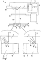
- the hologram master 2 is a holographically fabricated structure created by holographic imaging of a ground glass, as explained in greater detail below.
- the device 1 further includes a light source 5 capable of generating coherent light 8. This can be in the visible, ultraviolet or infrared spectral range.
- the light source 5 may include, for example, a laser 6, which generates coherent and usually momochromatic light.
- the light source 5 may comprise a monochromator 7 which monochromatizes the coherent light when, for example, another light generating unit is used instead of the laser 6 or the laser 6 produces light of several wavelengths.
- the coherent light 8 is preferably provided by the light source 5 as a stripe-shaped light beam.
- the light beam is extended transversely to the propagation direction along a spatial dimension.
- This extension preferably corresponds to at least one width of the hologram to be produced.
- the coherent light 8 is stretched perpendicular to the plane of the strip.
- the device 1 further comprises an imaging optics, which is shown here in simplified form as a deflection mirror 9.
- the imaging optics are designed such that the coherent light 8 is passed through a spatial light modulator 10 in which it is spatially modulated. This means that different positions along the strip-shaped extension of the coherent light 8 modulate differently across the propagation direction become. Likewise, the modulation is dependent on a lateral position at which the light passes through the spatial light modulator. The modulation takes place according to an individualization pattern for the hologram.
- the modulated coherent light beam 11 passes through the holographic recording material 4 and is at least partially diffracted and / or reflected by the hologram master 2.
- the reflected and / or diffracted light interferes with the light 11 penetrating the holographic recording material, thus exposing the hologram to the holographic recording material 4.
- a control unit 12 of the device 1 is designed to control a relative movement of the coherent light 8 or modulated coherent light 11 on the one hand and the holographic recording material 4 and the hologram master 2 on the other hand.
- the control unit 12 is connected to a drive unit 13. This is in the illustrated embodiment so with the imaging optics, i. coupled to the deflection mirror 9, that synchronized by a displacement of the deflection mirror of the Spatial Light modulator 10 and the hologram master 2 are scanned in strips.
- the control unit 12 is further configured such that an exposure time in the holographic recording material is adjusted in each case adapted to a spectral sensitivity of the holographic recording material 4 and to the wavelength of the coherent light 8, 11 used in each case for the exposure of the hologram.
- the required exposure time depends on the intensity of the coherent light and the spectral sensitivity of the holographic recording material 4.
- the control unit 12 can control either an intensity of the light source and / or a relative speed and / or an exposure time in a position of the holographic recording material 4.
- the exposure may be carried out in a so-called step-and-repeat method or continuously, for example in a drum exposure method.
- the hologram master is incorporated into a drum on which the holographic recording material rests. During the exposure, the drum rotates.
- a step-and-repeat method the area to be exposed of the film-formed holographic recording material is placed on the master and comes to rest there. This is followed by an exposure, for example, scanning or full surface, which makes the contact copy of the hologram.
- this laser beams are personalized or personalized.
- the holographic recording material formed as a film is transported on until the next unexposed area on the hologram master comes to rest.
- the hologram master 2 is illuminated in the illustrated example at an exposure angle 14 of 90 ° from the modulated coherent light 11 which has transmitted the holographic recording material.
- the hologram master 2 in the illustrated embodiment comprises a weaker scattering region 15 and a more scattering region 16. In both regions 15, 16 the light is reflected and / or diffracted into different angular ranges 17, 18 by the same exposure failure angle 19 of 45 °.
- the angular region of the more scattering region 16 includes angles of 45 ° ⁇ 20 ° and the weaker or less scattering region 15 comprises angles of 45 ° ⁇ 10 °.
- the intensities observed at the various angles depend on the particular angle. Both regions 15, 16 have an intensity distribution which starts at zero at a maximum deviation from the exposure failure angle 19, ie at 25 ° or 65 ° for the more scattering region 16 and at 35 ° or 55 ° for the weaker scattering region at zero and / or ends. The more one approaches the exposure failure angle 19, the greater the intensity in both intensity distributions. These each reach an intensity maximum at the exposure failure angle 19.
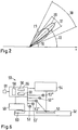
- FIG Fig. 2 is a polar diagram
- the intensity is given by a distance from the origin the angle is measured against the x-axis in the mathematically positive sense. It can be seen that the two intensity distributions have the same intensity at an excellent angle 22. At this angle, the reconstructions of the weaker scattering region 15 and the more scattering region 16 are equally intense or equally bright.
- the angle dependencies of the hologram master 2 explained here are transferred to the hologram exposed in the holographic recording material 4. The finished hologram is then preferably integrated into a security document.
- a security document with a hologram will be described below with reference to FIG Fig. 4a to 4d described in more detail.
- a flat transparent support 30 which may be formed for example as a polished glass plate
- different transparent coatings are applied, which form a corresponding layer 31 with a lower roughness and a layer 32 with a greater roughness (see. Fig. 3a ).
- the paint is preferably applied by printing, for example through-printing (screen printing), high-pressure (letterpress, letter set), gravure printing (gravure printing, intaglio printing), planographic printing (offset, wet offset, dry offset), digital printing (inkjet).
- the carrier 30 with the layers 31, 32 represents a ground glass.
- the carrier 30 and the layers 31, 32 are then irradiated by coherent monochromatic light 34 of the wavelength which is adapted to the wavelength with which the hologram (cf. Fig.
- the holographic recording material 38 having a coherent reference light 39 so as to form a transmission hologram 40.
- This transmission hologram 40 becomes, as in Fig. 3b is reconstructed with coherent light 41 and further brought to this coherent reference light 42 in another recording material 43 to interference, so that the reconstruction of the transmission hologram 40 is exposed in the further holographic recording material 43 as a volume reflection hologram, which is used as hologram master 2 in the Device 1 according to Fig. 1 can be used. If the hologram master 2 is to be reconstructed for different wavelengths, then the process described must be carried out analogously with these wavelengths.
- Fig. 4a to 4d For example, four views of a security document 44 are shown below four different reconstruction geometries for a circular hologram 45.
- the four reconstruction geometries correspond to four different tilts of the security document 44 relative to a viewing direction and a direction of illumination.
- the hologram 45 includes a more scattering region 46 surrounding a cross-shaped weaker scattering region 47.
- the reconstruction geometry, with the view Fig. 4a corresponds most strongly with an optimal reconstruction geometry, whose corresponding view in Fig. 4d is shown.
- the Fig. 4b and 4c show views of the security document 44 and the hologram 45 for reconstruction geometries which approximates stepwise the optimal reconstruction geometry. Under the reconstruction geometry which deviates strongly from the optimal reconstruction geometry (cf. Fig.
- FIGS. 4a, 4b and 4d a view is shown, which corresponds to the excellent reconstruction geometry, in which both regions are perceived as bright (equal intensity). Opposite to the view Fig. 4b Both regions are brighter. In this position is also an individualization pattern, which is symbolized here by two circles 49, which could represent, for example, eyes of a passport photograph, well recognize and capture. A comparison with the others FIGS. 4a, 4b and 4d shows that this is not or not optimally possible among the other reconstruction geometries.
- Fig. 4d Finally, there is a view taken in the optimal reconstruction geometry.
- the two regions 46, 47 have both gained in brightness once again, but the weaker scattering region 47 is stronger than the more scattered region 46.
- Contrary to opinion Fig. 4a and 4b a contrast reversal has taken place, which can be used to verify the authenticity of the hologram 45 and / or the security document 44.
- FIG. 12 is a view of another security document 44 'on which a full face hologram 45' is mounted.
- the substrate of the security document 44 'on which the hologram 45' is mounted is a paper substrate comprising watermarks in three circular areas 48, 48 ', 48'. In these areas 48, 48 ', 48 ", roughness of the substrate is increased ,
- the hologram has circular, more scattering regions 46 ', 46 "and 46''', which preferably cover the circular areas in a congruent manner.
- 46 "and 46"' is greater than a range of scattering angles which the roughness of the paper substrate would cause in the regions 48, 48', 48 "of the watermarks
- Areas 48, 48 ', 48 "covered have a scattering characteristic that is matched to the roughness of the substrate outside of the circular areas 48, 48', 48", which means that an angular range in the weaker scattering region 47 'will contribute light the reconstruction scatters, or may come from the light at the reconstruction angle of incidence for a reconstruction, greater than o which is equal to an angular range of scattering caused by the roughness of the paper substrate outside the circular area 48, 48 ', 48 ".
- the angular range of the weaker scattering region 47 ' may also be greater than an angular range of scattering caused by the roughness in the regions 48, 48', 48 "However, in any case, the angular range of the scattering characteristic of the weaker scattering region 47 is smaller than that of the more scattering regions 46 ', 46 "and 46"'.
- a contrast inversion effect is maintained as the reconstruction geometry approaches the optimal reconstruction geometry.
- Fig. 5b is a view in the excellent reconstruction geometry shown, in which both regions are perceived as bright.
- Fig. 5c the view is shown at the optimal reconstruction geometry, where the weaker scattering region 47 'is brighter than the more scattering regions 46', 46 "and 46"'. Good to see is the contrast reversal that has taken place.
- the device 50 for verification comprises at least one, but preferably a plurality of light sources 53, 53 ', 53 ", 53''', ... which emit light of the wavelength with which the hologram 51 was generated in a time-shifted manner, the light sources 53, 53 ', 53 ", 53"', ... are arranged relative to the hologram 51 so that the hologram is illuminated at different angles.
- a detection unit 54 which is formed for example as a camera or CCD and the hologram 52 viewed at the reconstruction failure angle, the optimal viewing angle, the reconstructions of the hologram 51 are detected spatially resolved and brightness resolved.
- a control 55 controls both the multiple light sources 53, 53 ', 53 ", 53"',... And the detection unit 54. Furthermore, the control unit comprises an evaluation unit 56 which evaluates changes in the detected reconstructions of the hologram 51.
- Each of the multiple light sources is linked to a reconstruction geometry. By suitable control of the multiple light sources 53, 53 ', 53 ", 53'", ..., a contrast reversal can thus be determined by a comparison unit 58.
- the individualization pattern can be extracted by an extraction unit 57 and adjusted, if necessary, with information that is stored, for example, in a chip 60 integrated in the security document and can be detected via a further detection unit 59, which is embodied, for example, as a chip card reader. Via an output unit 61, a result of the verification is output.
Description
Die Erfindung betrifft ein Verfahren und eine Vorrichtung zum Herstellen von Hologrammen als Sicherheitselemente, insbesondere für Sicherheitsdokumente, sowie ein Verfahren zur Herstellung von Sicherheitsdokumenten, die solche Hologramme als Sicherheitselemente umfassen.
Als Sicherheitsdokumente werden alle Dokumente betrachtet, die gegen ein unbefugtes Kopieren und oder Fälschen geschützt werden sollen. Sicherheitsdokumente umfassen somit alle Arten von Identifikationsdokumenten, wie beispielsweise Reisepässe, Personalausweise, Identitätskarten, Führerscheine usw., Wertdokumente, aber beispielsweise auch Verpackungen beispielsweise von Medikamenten usw.
Sicherheitselemente dienen dazu, eine Echtheitsprüfung von Sicherheitsdokumenten zu ermöglichen. Eine Art von Sicherheitselementen stellen Hologramme dar. In Sicherheitselementen sind oftmals auch individualisierende Angaben enthalten. Bei Sicherheitselementen für oder von Identitätsdokumenten umfassen diese Angabe beispielsweise eine Seriennummer, eine Ausweisnummer, biometrische Daten, Bilder (Passbilder), etc. Diese können in Klarschrift bzw. Bildform oder optisch codiert bzw. maschinenlesbar vorgesehen sein.
Das grundsätzliche Vorgehen bei der Herstellung von individuellen Volumenhologrammen ist beispielsweise in der Literaturstelle
Security documents are all documents that are to be protected against unauthorized copying and / or counterfeiting. Security documents thus include all types of identification documents, such as passports, ID cards, identity cards, driving licenses, etc., documents of value, but also, for example, packaging, for example, of medicines, etc.
Security elements serve to enable authenticity checking of security documents. One type of security element is holograms. Security elements often include individualizing information. In the case of security elements for or from identity documents, this information includes, for example, a serial number, a card number, biometric data, pictures (passport pictures), etc. These can be provided in plain text or image form or optically coded or machine-readable.
The basic procedure in the production of individual volume holograms is for example in the reference
Um Hologramme zu individualisieren, kann das kohärente Licht durch einen Spatial Light Modulator moduliert werden. Hierdurch wird dem Hologramm ein Individualisierungsmuster aufgeprägt. Aus der Praxis sind digitale Projektoren bekannt, welche mit Spatial Light Modulatoren in Form von Liquid Crystal Displays (LCD) arbeiten. Die Funktionsweise entspricht beispielsweise der Projektion eines Dias, wobei der Spatial Light Modulator anstelle des Dias tritt.To individualize holograms, the coherent light can be modulated by a spatial light modulator. As a result, an individualization pattern is impressed on the hologram. From the practice of digital projectors are known which work with Spatial Light modulators in the form of liquid crystal displays (LCD). The function corresponds, for example, to the projection of a slide, with the Spatial Light Modulator replacing the slide.
Aus der Praxis sind des Weiteren digitale Projektoren bekannt, welche ein DMD (Digital Micro Mirror Device) als Spatial Light Modulator umfassen. Aus der Literaturstelle
Bei dem in
Wasserzeichen werden durch Strukturen hergestellt, welche sich in einem Sieb befinden, mit welchem der Papierbrei aus dem Wasser geschöpft wird. An Stellen, an denen das Sieb erhaben ist, sammeln sich weniger Fasern als an jenen Stellen, an welchen das Sieb Vertiefungen aufweist. Dort sammeln sich mehr Fasern. An den Stellen, an denen sich weniger Fasern befinden, ist das Papier durchsichtiger als an jenen Stellen, an denen sich mehr Fasern gesammelt haben. Im Durchlicht ist das Wasserzeichen ohne technische Hilfsmittel auch für einen Laien gut zu erkennen. Moderne Papiermühlen sind in der Lage, Muster, Schriftzeichen und andere grafische Darstellungen in unterschiedlichen Grautönen darzustellen.Watermarks are made by structures that are located in a sieve, with which the pulp is scooped out of the water. At locations where the screen is raised, fewer fibers accumulate than at those locations where the screen has recesses. There are more fibers collecting. At the points where there are fewer fibers, the paper is more transparent than at those points where more fibers have collected. In transmitted light, the watermark without technical aids is also easy to recognize for a layman. Modern paper mills are able to display patterns, characters and other graphic representations in different shades of gray.
Moderne Sicherheitsdokumente, wie Reisepässe, Verpackungen oder Echtheitszertifikate von Software, umfassen heute bereits Hologramme als Sicherheitselemente. Reisepässe und Personalausweise umfassen darüber hinaus häufig ein Hologramm, welches mit einem das Passbild darstellenden Individualisierungsmuster individualisiert ist. Bei einer fortschreitenden Verbreitung der technischen Geräte, die zur Herstellung von Hologrammen, insbesondere von individualisierten Hologrammen, benötigten werden, ist zu befürchten, dass Dokumentenfälscher einfache Hologramme nachahmen oder herstellen können. Benötigt werden somit Hologramme, deren Erzeugungsaufwand für Fälscher erhöht ist, wobei der erhöhte Aufwand zu mindestens einem zusätzlichen einfach zu verifizierenden Merkmal des Hologramms führen sollte.Modern security documents, such as passports, packaging or software certificates of authenticity, today already include holograms as security elements. Passports and identity cards also often include a hologram, which is individualized with an individualization pattern representing the passport photo. With the proliferation of technical equipment needed to produce holograms, particularly individualized holograms, it is feared that document counterfeiters could mimic or produce simple holograms. Thus, holograms are required whose production costs for counterfeiters are increased, whereby the increased expense should lead to at least one additional feature of the hologram which is easy to verify.
In
Aus der
Aus der
Aus der
Im Internet konnte unter der URL:https;//www.mastercard.com/ca/wce/PDF/Final May 27 08 Lay By Card.pdf am 11. Dezember 2015 ein Dokument mit dem Titel "The MasterCard Card Security Features and Optional Card Features abgerufen werden, welches eine Kreditkarte mit einem Hologramm als Sicherheitsmerkmal beschreibt.On the Internet at the URL: https; // www.mastercard.com/ca/wce/PDF/Final May 27 08 Lay By Card.pdf on December 11, 2015, a document titled "The MasterCard Card Security Features and Optional Card features that describes a credit card with a hologram as a security feature.
Unter der URL:https;//www.mastercard.com/uk/merchant/en/downloads/10862 MasterCard Card Identification Features.pdf konnte am 24. August 2016 ein Dokument mit dem Titel "MasterCard Card Identification Features" abgerufen werden, in dem ebenfalls holografische Sicherheitsmerkmale für eine Kreditkarte beschrieben sind.At the URL: https; // www.mastercard.com/uk/merchant/en/downloads/10862 MasterCard Card Identification Features.pdf was able to retrieve a document entitled "MasterCard Card Identification Features" on August 24, 2016, in which also holographic security features for a credit card are described.
In der
In der
Der Erfindung liegt somit die technische Aufgabe zugrunde, ein Herstellungsverfahren sowie eine Vorrichtung zum Herstellen von Hologrammen sowie solche Hologramme und Sicherheitsdokumente selbst sowie ein Verfahren zum Herstellen solcher Sicherheitsdokumente mit einem Hologramm als Sicherheitselement zu schaffen, bei denen das Hologramm gegenüber den bekannten Hologrammen schwieriger durch Fälscher herzustellen ist und dennoch eine zuverlässige Verifikation und auch eine Großserienfertigung von Hologrammen, insbesondere individualisierten Hologrammen möglich ist.The invention is therefore based on the technical object of providing a production method and an apparatus for producing holograms as well as such holograms and security documents themselves as well as a method for producing such security documents with a hologram as a security element, in which the hologram faces The known holograms difficult to produce by counterfeiters and yet reliable verification and also a large-scale production of holograms, especially individualized holograms is possible.
Ein Sicherheitselement ist eine bauliche Einheit, die zumindest ein Sicherheitsmerkmal umfasst. Ein Sicherheitselement kann eine selbstständige bauliche Einheit sein, die mit einem Sicherheitsdokument, welches auch ein Wertdokument sein kann, verbunden, beispielsweise verklebt, werden kann. Es kann sich aber auch um einen integralen Bestandteil eines Sicherheitsdokumentes handeln. Ein Beispiel für Erstes ist ein auf ein Sicherheitsdokument aufklebbares Visum. Ein Beispiel für Letzteres ist ein in einen Geldschein oder einen Ausweis integriertes, beispielsweise einlaminiertes Hologramm.A security element is a structural unit comprising at least one security feature. A security element can be a self-contained structural unit with a security document, which may also be a value document, connected, for example, glued, can be. But it can also be an integral part of a security document. An example of the first is a visa sticking on a security document. An example of the latter is a hologram integrated into a bill or passport, for example laminated.
Ein Sicherheitsmerkmal ist eine Struktur, die nur mit (gegenüber einfachem Kopieren) erhöhtem Aufwand oder gar nicht unautorisiert herstellbar bzw. reproduzierbar ist.A security feature is a structure that can only be produced or reproduced with (compared to simple copying) increased effort or not at all unauthorized.
Ein Muster besteht typischerweise aus einer Vielzahl nebeneinander angeordneter Mustereinheiten bzw. Pixel. Die Mustereinheiten bzw. Pixel eines Musters sind einander zugeordnet und in definierter Weise lateral zueinander angeordnet, typischerweise in ein oder zwei Raumdimensionen, und ergeben in der Gesamtbetrachtung eine Darstellung, beispielsweise ein Bild, ein Symbol, ein Logo, einen Schriftzug (Buchstaben, Zahlen, alphanumerisch) oder einen Code (z.B. einen Barcode). Ein Individualisierungsmuster ist ein Muster, welches zur Individualisierung verwendet wird.A pattern typically consists of a multiplicity of juxtaposed pattern units or pixels. The pattern units or pixels of a pattern are associated with one another and arranged laterally in a defined manner, typically in one or two spatial dimensions, and overall give a representation, for example a picture, a symbol, a logo, a lettering (letters, numbers, alphanumeric) or a code (eg a barcode). An individualization pattern is a pattern that is used for individualization.
Als Sicherheitsdokumente seien lediglich beispielhaft genannt: Personalausweise, Reisepässe, ID-Karten, Zugangskontrollausweise, Visa, Steuerzeichen, Tickets, Führerscheine, Kraftfahrzeugpapiere, Wertdokumente, wie Banknoten, Schecks, Postwertzeichen, Kreditkarten, beliebige Chipkarten und Haftetiketten (z.B. zur Produktsicherung). Solche Sicherheitsdokumente weisen typischerweise ein Substrat, eine Druckschicht und optional eine transparente Deckschicht auf. Ein Substrat ist eine Trägerstruktur, auf welche die Druckschicht mit Informationen, Bildern, Mustern und dergleichen aufgebracht wird. Als Materialien für ein Substrat kommen alle fachüblichen Werkstoffe auf Papier- und/oder Kunststoffbasis in Frage. Ein Substrat wird auch genutzt, um hierauf ein Hologramm als Sicherheitselement auf- oder anzubringen.By way of example only: identity cards, passports, ID cards, access cards, visas, tax stamps, tickets, driving licenses, motor vehicle papers, documents of value such as banknotes, checks, postage stamps, credit cards, any smart card and adhesive label (for example for product security). Such security documents typically comprise a substrate, a print layer and optionally a transparent cover layer. A substrate is a support structure to which the print layer is applied with information, images, patterns, and the like. Suitable materials for a substrate are all customary materials based on paper and / or plastic in question. A substrate is also used to mount or attach a hologram thereto as a security element.
Ein Spatial Light Modulator (SLM) erlaubt eine zweidimensional ortsaufgelöste Beleuchtung bzw. Bestrahlung eines meist flächigen Gegenstandes mit modulierter Intensität. Hierbei kann es sich beispielsweise um einen DMD (Digital Micro Mirror Device) Chip, ein LCD (Liquid Crystal Display) Transmissionsdisplay oder ein LCoS (Liquid Crystal on Silicon) Display handeln. Allen ist gemeinsam, dass eine Vielzahl von SLM-Pixeln gebildet ist, wobei jedes SLM-Pixel unabhängig von anderen SLM-Pixeln aktivierbar oder deaktivierbar ist (auch Zwischenstufen sind möglich), wodurch durch entsprechende Ansteuerung der SLM-Pixel sich Muster oder Bilder projizieren lassen. Durch die freie Ansteuerbarkeit können auch ohne weiteres verschiedene Bilder oder Muster in zeitlicher Folge hintereinander generiert werden, beispielsweise in Form eines Passfotos.
Ein Code bzw. Muster ist individualisierend, wenn er einzigartig für eine Person oder einen Gegenstand oder eine Gruppe von Personen oder Gegenständen aus einer größeren Gesamtmenge an Personen oder Gegenständen ist. Ein für eine Gruppe von Personen innerhalb der Gesamtmenge der Einwohner eines Landes individualisierender Code ist beispielsweise die Stadt des Wohnortes. Ein für eine Person individualisierender Code ist beispielsweise die Nummer des Personalausweises oder das Passbild. Ein für eine Gruppe von Geldscheinen innerhalb der Gesamtmenge der Geldscheine individualisierender Code ist die Wertigkeit. Für einen Geldschein individualisierend ist die Seriennummer. Beispiele für nicht individualisierende Codes bzw. Muster sind Wappen, Siegel, Hoheitszeichen, etc.
Ein holografisches Aufzeichnungsmaterial ist eine Schicht aus einem Material, welches photosensitiv ist, und in welcher sich Holografien durch irreversible, aber auch reversible photochemische und/oder photophysikalische Prozesse im Wege der Belichtung speichern lassen. Lediglich beispielhaft seien die in der Holografie oft verwendeten Photopolymere genannt.
Unter dem Begriff Rekonstruktionsgeometrie wird allgemein eine Geometrie verstanden, die zum Rekonstruieren eines Hologramms verwendet wird. Diese ist durch einen Einfallwinkel des zur Beleuchtung genutzten Lichts und einen Ausfallwinkel, unter dem das Hologramm betrachtet wird, gekennzeichnet. Beide Winkel können unabhängig von einander variiert werden, um eine Rekonstruktionsgeometrie zu verändern. Eine optimale Rekonstruktionsgeometrie ist jene Geometrie, bei der das Hologramm optimal rekonstruiert wird.
Ein Belichtungseinfallwinkel ist der Winkel, unter dem ein Masterhologramm bei einem Kontaktkopiervorgang belichtet wird, um dieses optimal zu rekonstruieren. Der Winkel, unter dem die Rekonstruktion optimal zu beobachten ist, wird als Belichtungsausfallwinkel bezeichnet. Der Wortbestandteil "Belichtungs-" soll andeuten, dass die Rekonstruktion während der Belichtung eines bei dem Kontaktkopiervorgang erzeugten Hologramms erfolgt. Bei einem solchen fertig gestellten Hologramm wird der Winkel, unter dem das Hologramm für eine Rekonstruktion optimal beleuchtet wird, als Rekonstruktionseinfallwinkel bezeichnet, der Winkel unter dem das Hologramm optimal betrachtet werden kann, wird entsprechend als Rekonstruktionsausfallwinkel bezeichnet. Eine Rekonstruktionsgeometrie, bei der die Beleuchtung unter dem Rekonstruktionseinfallwinkel erfolgt und die Betrachtung unter dem Rekonstruktionsausfallwinkel vorgenommen wird, ist somit die optimale Rekonstruktionsgeometrie. Einfallwinkel und Ausfallwinkel, die bei einer Rekonstruktion verwendet werden, jedoch nicht die optimale Rekonstruktionsgeometrie kennzeichnen, werden hier nicht als Rekonstruktionseinfallwinkel oder Rekonstruktionsausfallwinkel bezeichnet.
Grundzüge der Erfindung und bevorzugte Ausführungsformen
Zur Lösung der technischen Aufgabe wird ein Verfahren zum Herstellen eines Hologramms mit den Merkmalen des Anspruchs 1, ein Verfahren zum Herstellen eines Sicherheitsdokuments mit den Merkmalen des Anspruchs 7, ein Hologramm mit den Merkmalen des Anspruchs 6, sowie ein Sicherheitsdokument mit den Merkmalen des Anspruchs 8 und eine Vorrichtung zum Herstellen eines Hologramms mit den Merkmalen des Anspruchs 9 vorgeschlagen. Insbesondere wird ein Verfahren zum Herstellen eines Hologramms umfassend die Schritte vorgeschlagen: Bereitstellen eines Hologrammmasters; Anordnen eines holografischen Aufzeichnungsmaterials vor dem Hologrammmaster; Erzeugen kohärenten Lichts und Durchstrahlen des holografischen Aufzeichnungsmaterials mit dem kohärenten Licht, so dass ein Teil des Lichts an dem in Ausbreitungsrichtung des kohärenten Lichts hinter dem holografischen Aufzeichnungsmaterial angeordneten Hologrammmaster in das holografische Aufzeichnungsmaterial zurückreflektiert oder gebeugt wird, um mit dem das holografische Aufzeichnungsmaterial durchstrahlenden kohärenten Licht zu interferieren und so das Hologramm in das Aufzeichnungsmaterial zu belichten, wobei der Hologrammmaster mit mindestens zwei Regionen unterschiedlicher Streucharakteristik bereitgestellt und/oder erzeugt wird, die jeweils unter einem gleichen Belichtungseinfallwinkel einfallendes monochromatisches kohärentes Licht abhängig von ihrer Streucharakteristik in unterschiedlich große begrenzte Winkelbereiche um denselben Belichtungsausfallwinkel reflektieren und/oder beugen.
Erfindungsgemäß umfasst das Bereitstellen des Hologrammmasters ein Herstellen eines Masterhologramms, welches folgende Schritte umfasst: Bereitstellen eines Trägers, Erzeugen von mindestens zwei Regionen unterschiedlicher Oberflächenrauigkeit, so dass der Träger beim Durchstrahlen mit Licht, dieses in den mindestens zwei unterschiedlichen Regionen unterschiedlich streut; Abbilden des die mindestens zwei Regionen aufweisenden Trägers in ein Transmissionshologramm, Rekonstruieren des Transmissionshologramms und Belichten des Rekonstruktionsbilds in ein Volumen-Reflexionshologramm ausgebildet wird, welches der Hologrammmaster ist.
Diese Streucharakteristiken der beiden Regionen des Hologrammmasters übertragen sich auf das hergestellte Hologramm. Dieses weist somit mindestens zwei Regionen auf, die hinsichtlich ihrer Winkelabhängigkeit oder Winkeltoleranz gegenüber einer optimalen Rekonstruktion voneinander unterscheiden, jedoch optimal unter derselben Rekonstruktionsgeometrie (der optimalen Rekonstruktionsgeometrie) rekonstruierbar sind.
Eine Vorrichtung zur Herstellung eines solchen Hologramms umfasst einen Hologrammmaster, eine Aufnahme und/oder Führung für ein holografisches Aufzeichnungsmaterial und eine Lichtquelle, die kohärentes Licht emittiert, sowie eine Abbildungsoptik zum Führen des kohärenten Lichts, um das holografische Aufzeichnungsmaterial mit dem kohärenten Licht zu durchstrahlen, so dass zumindest ein Teil des kohärenten Lichts an dem Hologrammmaster gebeugt und/oder reflektiert wird, um mit dem das holografische Aufzeichnungsmaterial durchstrahlenden kohärenten Licht in dem holografischen Aufzeichnungsmaterial zu interferieren, wobei der Hologrammmaster mindestens zwei Regionen unterschiedlicher Streucharakteristik umfasst, die jeweils unter einem gleichen Belichtungseinfallwinkel einfallendes kohärentes Licht abhängig von ihrer Streucharakteristik in unterschiedlich große begrenzte Belichtungsausfallwinkelbereiche um denselben Belichtungsausfallwinkel reflektierend beugen, wobei der Hologrammmaster ein als ein Volumen-Reflexionshologramm ausgebildetes Masterhologramm ist, das mittels eine Verfahrens hergestellt ist, das folgende Schritte umfasst: Bereitstellen eines Trägers, Erzeugen von mindestens zwei Regionen unterschiedlicher Oberflächenrauigkeit, so dass der Träger beim Durchstrahlen mit Licht, dieses in den mindestens zwei unterschiedlichen Regionen unterschiedlich streut; Abbilden des die mindestens zwei Regionen aufweisenden Trägers in ein Transmissionshologramm , Rekonstruieren des Transmissionshologramms und Belichten des Rekonstruktionsbilds in das Masterhologramm, so dass dieses als das Volumen-Reflexionshologramm ausgebildet wird. Es ergibt sich ein Hologramm mit wasserzeichenartiger Struktur, welches unter einem Rekonstruktionseinfallwinkel einfallendes Licht bei einer Rekonstruktion in einen Rekonstruktionsausfallwinkel reflektiert und/oder beugt, wobei das Hologramm mindestens zwei Regionen umfasst, die aus unterschiedlich großen Winkelbereichen um den Rekonstruktionseinfallwinkel einfallendes Licht in entsprechende unterschiedlich große Winkelbereiche um den Rekonstruktionsausfallwinkel reflektieren. Ein erfindungsgemäßes Sicherheitsdokument umfasst ein erfindungsgemäßes Hologramm. Es wird mit einem Verfahren hergestellt, welches die Schritte zum Herstellen eines Hologramms und zusätzlich den Schritt umfasst, das Hologramm auf einem Substrat anzubringen oder aufzubringen, d.h., das Hologramm in das Sicherheitsdokument zu integrieren. Obwohl eine hohe Wellenlängenselektivität erhalten bleibt, existieren für das sich ergebende Hologramm verschiedene Rekonstruktionsgeometrien, die unterschiedliche Resultate ergeben.
Eine Verifizierung wird somit nach einem Verfahren mit folgenden Schritten ausgeführt: Erfassen einer Rekonstruktion des Hologramms unter mindestens zwei vorgegebenen Rekonstruktionsgeometrien, die an die Winkelbereiche der Streucharakteristiken der mindestens zwei Regionen angepasst sind, und Auswerten von Unterschieden der erfassten Rekonstruktionen und Vergleichen der Unterschiede mit vorgegebenen Unterschieden, Treffen einer Verifikationsentscheidung anhand des Vergleichsergebnisses und Ausgeben der Verifikationsentscheidung. Angepasst an die Winkelbereiche der Streucharakteristiken bedeutet, dass die die vorgegebenen Rekonstruktionsgeometrien festlegenden Winkel so gewählt sind, dass sich deutliche Unterschiede in den Rekonstruktionen zeigen, die auf die unterschiedlichen Streucharakteristiken bzw.
Winkelbereiche der mindestens zwei Regionen zurückzuführen sind. Eine Vorrichtung zur automatisierten Verifizierung eines solchen Hologramms oder eines Sicherheitsdokuments mit einem solchen Hologramm umfasst daher mindestens eine Lichtquelle, die Licht der Wellenlänge erzeugt, mit welchem das Hologramm belichtet ist, und eine Erfassungseinrichtung zum Erfassen einer Rekonstruktion des Hologramms, wobei eine Beleuchtung und Erfassung unter mindestens zwei voneinander abweichenden vorgegebenen Rekonstruktionsgeometrien ausführbar ist, und die Erfassungseinrichtung mit einer Auswerteeinheit gekoppelt ist, die Unterschiede der Rekonstruktionen mit vorgegebenen erwarteten Unterschieden vergleicht und eine Ausgabeeinrichtung zum Ausgeben des Vergleichsergebnisses umfasst. Während unter der optimalen Rekonstruktionsgeometrie beide Regionen rekonstruieren, existiert mindestens eine Rekonstruktionsgeometrie, unter der nur eine stärker streuende der mindestens zwei Regionen rekonstruiert, d.h., wahrnehmbar ist. Die Verifizierung kann jedoch auch auf einfache Weise durch Kontrollpersonal ausgeführt werden. Da der beschriebene Effekt von einer geeigneten Betrachtung ähnlich wie bei einem Wasserzeichen in einem Papier abhängt, wird dieser Effekt auch als wasserzeichenartiger Effekt bezeichnet und die sich ergebende Struktur im hergestellten Hologramm als wasserzeichenartige Struktur. Gegenüber Hologrammen, die unter verschiedenen Winkeln mehrfach belichtet sind, bei denen sich auch Veränderungen ähnlicher Art erzielen lassen, kann ein erfindungsgemäßes Hologramm sehr viel einfacher hergestellt werden.
Um ein einfaches Masterhologramm nutzen zu können, welches nur für eine Wellenlänge selektiv ist und mit dem eine höhere Beugungseffizienz zu erreichen ist, ist auch eine Beleuchtung mit monochromatischem Licht dieser Wellenlänge vorteilhaft. Bei einer bevorzugten Ausführungsform ist daher vorgesehen, dass das Licht monochromatisch erzeugt wird oder monochromatisiert wird. Bei einer vorteilhaften Ausführungsform der Vorrichtung zur Herstellung umfasst die Lichtquelle einen Laser, der monochromatisches Licht erzeugt. Alternativ kann ein Monochromator vorgesehen sein. Dem Fachmann sind unterschiedliche Vorrichtungen zur Monochromatisierung von kohärentem Licht bekannt.
Andere Ausführungsformen sehen vor, dass der Hologrammmaster Licht unterschiedlicher Wellenlängen, d.h. Farben, reflektiert und/oder beugt. Hierfür kann ein mit unterschiedlichen Wellenlängen belichtetes Masterhologramm verwendet werden.
Es kann somit vorgesehen sein, dass das kohärente Licht zeitgleich oder zeitversetzt mit mehreren unterschiedlichen Wellenlängen erzeugt wirdA Spatial Light Modulator (SLM) allows a two-dimensionally spatially resolved illumination or irradiation of a mostly flat object with modulated intensity. This may be, for example, a DMD (Digital Micro Mirror Device) chip, an LCD (Liquid Crystal Display) transmission display or LCoS (Liquid Crystal on Silicon) display. All have in common that a multiplicity of SLM pixels is formed, wherein each SLM pixel is activatable or deactivatable independently of other SLM pixels (intermediate stages are also possible), whereby by appropriate control of the SLM pixels, patterns or images can be projected , Due to the free controllability can also readily different images or patterns in time sequence can be generated one behind the other, for example in the form of a passport photo.
A code or pattern is individualizing if it is unique to a person or an object or a group of persons or objects from a larger total of persons or objects. For example, a code individualizing a group of persons within the total population of a country is the city of residence. An individualizing for a person code, for example, the number of the identity card or passport photo. A code individualizing a group of bills within the total amount of bills is the value. Individualizing for a banknote is the serial number. Examples of non-individualizing codes or patterns are coats of arms, seals, insignia, etc.
A holographic recording material is a layer of a material that is photosensitive, and in which holograms can be stored by irreversible, but also reversible photochemical and / or photophysical processes by exposure. By way of example only, the photopolymers often used in holography may be mentioned.
The term reconstruction geometry is generally understood to mean a geometry that is used to reconstruct a hologram. This is characterized by an angle of incidence of the light used for illumination and a failure angle at which the hologram is viewed. Both angles can be varied independently of each other to change a reconstruction geometry. An optimal reconstruction geometry is the geometry in which the hologram is optimally reconstructed.
An exposure incidence angle is the angle at which a master hologram is exposed in a contact copying operation to optimally reconstruct it. The angle at which the reconstruction is optimally observed is called the exposure failure angle. The word component "exposure" is intended to indicate that the reconstruction occurs during the exposure of a hologram generated in the contact copying process. In such a finished hologram, the angle at which the hologram is optimally illuminated for reconstruction is referred to as the reconstruction incident angle, and the angle at which the hologram can be optimally viewed is referred to as the reconstruction failure angle. A reconstruction geometry in which the Lighting under the reconstruction angle of incidence and viewing under the reconstruction failure angle is thus the optimal reconstruction geometry. Angle of incidence and angles of attack used in a reconstruction but not characterizing the optimal reconstruction geometry are not referred to herein as reconstruction angle of incidence or reconstruction failure angle.
Broad features of the invention and preferred embodiments
To solve the technical problem, a method for producing a hologram with the features of claim 1, a method for producing a security document with the features of
According to the invention, the provision of the hologram master comprises producing a master hologram comprising the following steps: providing a carrier, producing at least two regions of different surface roughness, so that the carrier, when irradiated with light, diffuses it differently in the at least two different regions; Mapping the at least two regions Carrier is formed in a transmission hologram, reconstructing the transmission hologram and exposing the reconstruction image in a volume reflection hologram, which is the hologram master.
These scattering characteristics of the two regions of the hologram master are transferred to the hologram produced. This therefore has at least two regions which differ from each other in terms of their angular dependence or angular tolerance with respect to optimal reconstruction, but can be optimally reconstructed under the same reconstruction geometry (the optimal reconstruction geometry).
An apparatus for producing such a hologram comprises a hologram master, a recording and / or guide for a holographic recording material and a light source emitting coherent light, and imaging optics for guiding the coherent light to irradiate the holographic recording material with the coherent light, such that at least a portion of the coherent light is diffracted and / or reflected at the hologram master to interfere with the coherent light radiating through the holographic recording material in the holographic recording material, the hologram master comprising at least two regions of different scattering characteristics, each at a same exposure angle of incidence incident coherent light depending on their Streucharakteristik in different sized limited Ausstellungsungsfallfallwinkelbereiche reflectively by the same Existungsausfallwinkel bend, the hologr ammmaster is a master hologram formed as a volume reflection hologram made by a method comprising the steps of: providing a carrier, producing at least two regions of different surface roughness so that the substrate, when irradiated with light, will be in the at least two different ones Regions scattered differently; Mapping the carrier having the at least two regions into a transmission hologram, reconstructing the transmission hologram, and exposing the reconstruction image to the master hologram so that it is formed as the volume reflection hologram. The result is a hologram with a watermark-like structure which reflects and / or diffracts light incident at a reconstruction incident angle into a reconstruction failure angle, wherein the hologram comprises at least two regions which, from differently sized angle regions around the reconstruction incident angle, enter corresponding differently sized light Reflect angle ranges around the reconstruction failure angle. A security document according to the invention comprises a hologram according to the invention. It is made by a method comprising the steps of making a hologram and additionally comprising the step of mounting or applying the hologram to a substrate, ie, integrating the hologram into the security document. Although high wavelength selectivity is maintained, the resulting hologram has different reconstruction geometries giving different results.
Verification is thus performed according to a method comprising the steps of: detecting a reconstruction of the hologram among at least two predetermined reconstruction geometries adapted to the angular ranges of the scattering characteristics of the at least two regions, and evaluating differences of the detected reconstructions and comparing the differences with predetermined differences Making a verification decision based on the comparison result and issuing the verification decision. Adapted to the angular ranges of the scattering characteristics means that the angles defining the given reconstruction geometries are selected in such a way that clear differences in the reconstructions, which are based on the different scattering characteristics or
Angular ranges of at least two regions are due. An apparatus for automated verification of such a hologram or security document with such a hologram therefore comprises at least one light source that generates light of the wavelength with which the hologram is exposed, and a detection device for detecting a reconstruction of the hologram, wherein a lighting and detection under at least two different predetermined reconstruction geometries can be executed, and the detection device is coupled to an evaluation unit, which compares differences of the reconstructions with predetermined expected differences and comprises an output device for outputting the comparison result. While both regions are reconstructed under the optimal reconstruction geometry, there exists at least one reconstruction geometry under which only one more strongly scattering of the at least two regions is reconstructed, ie, perceptible. However, the verification can also be carried out in a simple manner by control personnel. Since the described effect depends on proper viewing similar to a watermark in a paper, this effect is also referred to as a watermark effect, and the resulting structure in the manufactured hologram as a watermarked structure. Compared to holograms, which are exposed several times at different angles, at which also changes of a similar nature can be achieved, a hologram according to the invention can be made much easier.
In order to be able to use a simple master hologram, which is selective for only one wavelength and with which a higher diffraction efficiency can be achieved, it is also advantageous to use monochromatic light of this wavelength. In a preferred embodiment it is therefore provided that the light is monochromatically generated or monochromatized. In an advantageous embodiment of the device for producing the light source comprises a laser which generates monochromatic light. Alternatively, a monochromator may be provided. The person skilled in various devices for monochromatization of coherent light are known.
Other embodiments provide that the hologram master reflects and / or diffracts light of different wavelengths, ie colors. For this purpose, an illuminated with different wavelengths master hologram can be used.
It can thus be provided that the coherent light is generated at the same time or with a time delay with several different wavelengths
Um eine Fälschungssicherheit zu erhöhen und eine Überprüfbarkeit einer Zuordnung des hergestellten Hologramms zu einem Individuum oder einem bestimmten Produkt usw. zu ermöglichen, ist bei einer bevorzugten Ausführungsform vorgesehen, dass das kohärente Licht vor dem Durchstrahlen des holografischen Aufzeichnungsmaterials örtlich gemäß einem Individualisierungsmuster moduliert wird. Es ergibt sich somit ein individualisiertes Hologramm. Die Modulation des Lichts wird mit einem Spatial Light Modulator vorgenommen. Als Spatial Light Modulatoren kommen insbesondere Liquid Crystal on Silicon, DMDs und LCD-Displays in Betracht. Das Individualisierungsmuster ist vorzugsweise so gewählt, dass es sich zumindest zum Teil über die mindestens zwei Regionen erstreckt. Somit ist das Sicherheitsmerkmal, welches durch das Individualisierungsmuster gegeben ist, mit dem wasserzeichenartigen Effekt des erfindungsgemäßen Hologramms verknüpft. Deshalb ist die Fälschung dieses kombinierten Sicherheitsmerkmals deutlich erschwert.
Die Regionen des Masterhologramms sind bei einer bevorzugten Weiterbildung der Erfindung so ausgestaltet, dass die Intensitätsverteilungen des gestreuten Lichts über die die Streucharakteristiken der mindestens zwei Regionen festlegenden Winkelbereiche nicht konstant sind. Vorzugsweise ist eine Streuintensität unter dem Belichtungsausfallwinkel, der dem optimalen Rekonstruktionsausfallwinkel entspricht, maximal und nimmt mit einer zunehmenden Winkelabweichung von diesem stetig ab. Da sich diese Eigenschaft eines Hologrammmasters auf das erzeugte Hologramm überträgt, ist es für einen Betrachter auf diese Weise einfach möglich festzustellen, ob er das Hologramm unter der optimalen Rekonstruktionsgeometrie betrachtet. Weisen die mindestens zwei rekonstruierten Regionen eine maximale Helligkeit auf, ist die optimale Rekonstruktionsgeometrie eingehalten. Führt eine Variation der Rekonstruktionsgeometrie zu einer Intensitätsabnahme (Helligkeitsabnahme) in einer der mindestens zwei Regionen, so zeigt dieses an, dass die optimale Rekonstruktionsgeometrie nicht mehr erfüllt ist.
Vorzugweise werden die Streucharakteristiken der mindestens zwei Regionen stark unterschiedlich gewählt. Eine erste Region stellt beispielsweise einen holografischen Spiegel dar, der Licht nur in einen sehr kleinen Winkelbereich um den optimalen Belichtungsausfallwinkel (oder Rekonstruktionsausfallwinkel (bei einem fertigen Hologramm)) streut. Mindestens eine zweite Region weist eine relativ starke Streuung auf. Die Streuintensitätsverteilungen sind nun vorzugsweise so gewählt, dass die Streuintensitäten über den jeweiligen zugehörigen Winkelbereich stetig von null bei einer maximalen Abweichung von dem Belichtungsausfallwinkel (Rekonstruktionsausfallwinkel (bei einem fertigen Hologramm)) bis eine Maximalintensität zunehmen und die Maximalintensitäten der mindestens zwei unterschiedlichen Regionen sich abhängig von einer Größe des zugehörigen Winkelbereichs unterscheiden. Eine maximale Streuintensität unter dem Belichtungsausfallwinkel (dem optimalen Rekonstruktionsausfallwinkel (bei einem fertigen Hologramm)) nimmt vorzugsweise ab, je größer der Winkelbereich ist, in den die Region streut. Ein solches Verhalten ergibt sich beispielsweise, wenn die über die entsprechenden Winkelbereiche integrierten Streuintensitäten in den mindestens zwei Regionen gleich sind. Die sich ergebenden Hologramme weisen nun bei der Rekonstruktion in Abhängigkeit von der Abweichung von einer optimalen Rekonstruktionsgeometrie eine Kontrastumkehr der beiden Regionen auf. Ist die Abweichung von der optimalen Rekonstruktionsgeometrie groß, so wird nur die stärker streuende Region der mindestens zwei Regionen "schwach" rekonstruiert. Nähert man sich der optimalen Rekonstruktionsgeometrie etwas an, so nimmt eine Helligkeit der Rekonstruktion der stärker streuenden Region der mindestens zwei Regionen zu. Die schwächer streuende Region der mindesten zwei Regionen ist noch nicht sichtbar. Bei einer noch stärkeren Annäherung an die optimale Rekonstruktionsgeometrie nimmt die Helligkeit der Rekonstruktion der stärker streuenden Region weiter zu und die Rekonstruktion der schwächer streuenden Region setzt ein. Zunächst ist jedoch die Helligkeit der stärker streuenden Region größer als die der schwächer streuenden Region. Bei einer weiteren Annäherung an die optimale Rekonstruktionsgeometrie wird eine ausgezeichnete geometrische Stellung erreicht, bei der die Helligkeit der schwächer streuenden Region die Helligkeit der stärker streuenden Region erreicht. In dieser ausgezeichneten Stellung sind beide Regionen gleich hell wahrnehmbar und für einen Betrachter wie eine vereinigte Region wahrnehmbar. Bei der optimalen Rekonstruktionsgeometrie wird schließlich die schwächer streunende Region als heller wahrgenommen, obwohl eine Helligkeit der stärker streuenden Region bei dieser Geometrie ebenfalls maximal ist. Dennoch findet beim "Überschreiten" der ausgezeichneten Rekonstruktionsgeometrie ein Kontrastwechsel zwischen der stärker streuenden Region und der schwächer streuenden Region der mindestens zwei Regionen statt. Die stärker streuende Region ist bei Abweichungen, die größer als bei der ausgezeichneten Rekonstruktionsgeometrie sind, heller als die schwächer streuende Region. Umgekehrt ist die schwächer streuende Region bei Abweichungen, die geringer als bei der ausgezeichneten Rekonstruktionsgeometrie sind, heller als die stärker streuende Region.In order to increase anti-counterfeiting security and to enable a verifiability of an association of the manufactured hologram to an individual or a specific product etc., it is provided in a preferred embodiment that the coherent light is locally modulated according to an individualization pattern prior to the radiation of the holographic recording material. This results in an individualized hologram. The modulation of the light is done with a Spatial Light Modulator. As Spatial Light modulators are in particular Liquid Crystal on Silicon, DMDs and LCD displays are considered. The individualization pattern is preferably chosen such that it extends at least partially over the at least two regions. Thus, the security feature given by the individualization pattern is associated with the watermarking effect of the hologram of the invention. Therefore, the falsification of this combined security feature is much more difficult.
In a preferred development of the invention, the regions of the master hologram are designed in such a way that the intensity distributions of the scattered light are not constant over the angular ranges defining the scattering characteristics of the at least two regions. Preferably, a scattering intensity at the exposure failure angle corresponding to the optimum reconstruction failure angle is maximum and steadily decreases with increasing angular deviation therefrom. Since this property of a hologram master translates to the generated hologram, it is thus easily possible for a viewer to determine whether he is viewing the hologram under the optimal reconstruction geometry. If the at least two reconstructed regions have maximum brightness, the optimal reconstruction geometry is maintained. If a variation of the reconstruction geometry leads to a decrease in intensity (decrease in brightness) in one of the at least two regions, this indicates that the optimal reconstruction geometry is no longer satisfied.
Preferably, the scattering characteristics of the at least two regions are chosen very differently. For example, a first region represents a holographic mirror that scatters light only in a very small angular range around the optimum exposure-loss angle (or reconstruction-failure angle (for a completed hologram)). At least one second region has a relatively high variance. The scattering intensity distributions are now preferably chosen such that the scattering intensities continuously increase from zero at a maximum deviation from the exposure failure angle (reconstruction failure angle (in the case of a finished hologram)) to a maximum intensity over the respective associated angular range and the maximum intensities of the at least two different regions increase depending on a size of the associated angle range differ. A maximum scattering intensity under the exposure failure angle (the optimal reconstruction failure angle (for a finished hologram)) preferably decreases as the angular range into which the region scatters increases. Such a behavior arises, for example, if the scatter intensities integrated in the at least two regions over the corresponding angular ranges are the same. The resulting holograms now point to the reconstruction depending on the deviation from an optimal reconstruction geometry, a contrast reversal of the two regions. If the deviation from the optimal reconstruction geometry is large, then only the more scattering region of the at least two regions is reconstructed "weakly". If one approximates something to the optimal reconstruction geometry, a brightness of the reconstruction of the more scattering region of the at least two regions increases. The weaker scattering region of at least two regions is not yet visible. With an even closer approach to the optimal reconstruction geometry, the brightness of the reconstruction of the more scattering region continues to increase and the reconstruction of the weaker scattering region begins. First, however, the brightness of the more scattering region is greater than that of the weaker scattering region. Further approximation to the optimal reconstruction geometry achieves an excellent geometric position, where the brightness of the weaker scattering region reaches the brightness of the more scattering region. In this excellent position, both regions are equally bright and perceptible to a viewer as a united region. Finally, with the optimal reconstruction geometry, the weaker stray region is perceived to be brighter, although a brightness of the more scattering region is also maximal in this geometry. Nevertheless, when the excellent reconstruction geometry is exceeded, there is a change in contrast between the more scattering region and the weaker scattering region of at least two regions. The more scattered region is brighter than the weaker scattering region for deviations larger than the excellent reconstruction geometry. Conversely, for deviations less than the excellent reconstruction geometry, the weaker scattering region is brighter than the more scattering region.
Bei einer Ausführungsform ist die Streucharakteristiken des Hologrammmasters so ausgebildet sind, dass die Intensitätsverteilungen der mindestens zwei Regionen unter einem (identischen) ausgezeichneten Winkel eine identische Intensität aufweisen.In one embodiment, the scattering characteristics of the hologram master are designed such that the intensity distributions of the at least two regions have an identical intensity at an (identical) excellent angle.
Ein gesamtes Individualisierungsmuster ist somit optimal nur unter der ausgezeichneten Rekonstruktionsgeometrie zu beobachten, bei der die Streuintensitäten der mindestens zwei Regionen gleich sind.An entire individualization pattern can thus be optimally observed only under the excellent reconstruction geometry, in which the scatter intensities of the at least two regions are the same.
Eine Oberflächenrauigkeit des Trägers lässt sich beispielsweise durch ein Auftragen eines vorzugsweise transparenten Lacks oder mehrerer vorzugsweise transparenter Lacke erreichen, die eine unterschiedliche Rauigkeit aufweisen. Hierdurch können die Regionen in ihrer geometrischen Ausgestaltung, d.h. bezüglich ihrer Form, einfach gestaltet werden. Der Lack wird vorzugsweise durch einen Druck aufgetragen, z.B. Durchdruck (Siebdruck), Hochdruck (Buchdruck, Letterset), Tiefdruck (Rastertiefdruck, Stichtiefdruck), Flachdruck (Offset, Naßoffset, Trockenoffset), Digitaldruck (Inkjet). Gebiete unterschiedlicher Rauigkeit lassen sich auch z.B. durch Aussparungen beim Bedrucken erreichen.
Alternativ kann eine streuende Folie verwendet werden, die Aussparungen oder Ausstanzungen umfasst. Diese wird auf den Träger aufgebracht. Statt Aussparungen oder Ausstanzungen ist es z.B. auch möglich, durch Heißprägen mit einer glatten Fläche die Rauigkeit am Ort des Prägestempels zu reduzieren.
Bei einer solchen Erzeugung des Hologrammmasters kann eine optimale Rekonstruktionsgeometrie für das Masterhologramm und hierüber auch für das herzustellende bzw. hergestellte Hologramm festgelegt werden. Vorzugsweise werden die Abbildungen in das Transmissionshologramm und das als Volumen-Reflexionshologramm ausgebildete Masterhologramm so vorgenommen, dass der Belichtungseinfallwinkel im Bereich zwischen 25° und 75°, bevorzugter im Bereich zwischen 40° und 50° liegt und am bevorzugtesten 45° beträgt und ein Belichtungsausfallwinkel im Bereich zwischen 80° und 135°, bevorzugter zwischen 80° und 100° liegt und am bevorzugtesten 90° beträgt, wobei die Winkel jeweils gegen die Oberfläche des Hologramms gemessen sind..
Es kann vorgesehen sein, dass zwischen den mindestens zwei Regionen eine Übergangsregion angeordnet ist, deren Streucharakteristik abhängig von einer Position zwischen den mindestens zwei Regionen stetig von der Streucharakteristik der einen der mindestens zwei Regionen in die Streucharakteristik der anderen der mindestens zwei Regionen übergeht.A surface roughness of the carrier can be achieved, for example, by applying a preferably transparent lacquer or more preferably transparent lacquers having a different roughness. This allows the regions in their geometric design, ie in terms of their shape, are designed to be simple. The paint is preferably applied by printing, for example through-printing (screen printing), high-pressure (letterpress, letter set), gravure printing (gravure printing, intaglio printing), planographic printing (offset, wet offset, dry offset), digital printing (inkjet). Areas of different roughness can also be achieved, for example, by recesses in the printing.
Alternatively, a scattering film may be used which includes recesses or punches. This is applied to the carrier. Instead of recesses or punches, for example, it is also possible to reduce the roughness at the location of the embossing stamp by means of hot embossing with a smooth surface.
In such a generation of the hologram master, an optimal reconstruction geometry for the master hologram and here also for the hologram to be produced or produced can be defined. Preferably, the images are made in the transmission hologram and the master hologram formed as a volume reflection hologram such that the exposure incidence angle is in the range between 25 ° and 75 °, more preferably in the range between 40 ° and 50 °, and most preferably 45 °, and an exposure failure angle in Range between 80 ° and 135 °, more preferably between 80 ° and 100 °, and most preferably 90 °, wherein the angles are measured in each case against the surface of the hologram.
It can be provided that a transition region is arranged between the at least two regions whose scattering characteristic, depending on a position between the at least two regions, continuously changes from the scattering characteristic of one of the at least two regions into the scattering characteristic of the other of the at least two regions.
Häufig ist eine Verwendung eines Hologramm in einem Sicherheitsdokument gewünscht, welches ein raues Substrat umfasst. Wird ein Hologramm mit mindestens zwei Regionen unterschiedlicher Streucharakteristik auf einem Substrat verwendet, welches rau ist, so ist die Streucharakteristik des schwächer streuenden Bereichs vorzugsweise mindestens so groß, dass das Hologramm unter der optimalen Rekonstruktionsgeometrie vollständig rekonstruiert. Es wird somit nach einer bevorzugten Ausführungsform ein Sicherheitsdokument hergestellt, dass ein Substrat mit einer Rauigkeit umfasst, auf dem das Hologramm angebracht wird, bei dem das Hologramm so hergestellt wird, dass der Hologrammmaster so bereitgestellt wird, dass eine schwächer streuende Region der mindestens zwei Regionen so an die Rauigkeit des Substrats angepasst ist, dass ein zughöriger Winkelbereich mindestens so groß ist, dass bei einer Rekonstruktion des auf dem Substrat angebrachten hergestellten Hologramms unter einer optimalen Rekonstruktionsgeometrie das gesamte Hologramm rekonstruiert. Dieses bedeutet, dass der Winkelbereich der schwächer streuenden Region größer ist als ein Winkelbereich einer Streucharakteristik, die für eine Kompensation der Rauigkeit des Substrats notwendig ist. Wird eine Region, die als holografischer Spiegel ausgebildet ist und Licht, das unter dem Rekonstruktionseinfallwinkel auftrifft, nur in den Rekonstruktionsausfallwinkel beugt oder reflektiert, auf ein raues Substrat aufgebracht, so ändert sich das Rekonstruktionsverhalten dieser Region aufgrund der Rauigkeit des Substrats, die das Hologramm lokal beeinflusst. In dieser Region rekonstruiert das Hologramm nur an einigen Stellen, an anderen hingegen nicht. Durch die lokale "Verformung" des Hologramms aufgrund der Rauigkeit des Substrats trifft das Licht nur an einigen Stellen unter dem Rekonstruktionseinfallwinkel auf. An den übrigen Stellen trifft das Licht unter einem abweichenden Winkel auf, so dass keine Rekonstruktion stattfindet. Je größer die Rauigkeit des Substrats in der Region ist, desto größere Flächenanteile "rekonstruieren" bei einer Betrachtung unter dem Rekonstruktionsausfallwinkel nicht. Eine Streucharakteristik einer Region eines Hologramms gilt als angepasst an eine Rauigkeit eines Substrats, wenn das Hologramm, welches auf das Substrat aufgebracht ist, trotz der "Verformung" aufgrund der Rauigkeit vollständig bei einer Betrachtung unter dem Rekonstruktionsausfallwinkel rekonstruiert, wenn es mit Licht unter dem Rekonstruktionseinfallwinkel beleuchtet wird. Wird ein homogenes Hologramm mit einer einheitlichen Streucharakteristik auf dem Substrat einheitlicher Rauigkeit angebracht und ist die Streucharakteristik an die Rauigkeit optimal angepasst, so ist bei einer Abweichung der Rekonstruktionsgeometrie von der optimalen Rekonstruktionsgeometrie keine oder nur eine sehr viel schwächere Intensitätsabhängigkeit von dieser Abweichung zu beobachten als bei einer Verwendung des Hologramms auf einem glatten Substrat. Ist jedoch die Streucharakteristik einer Region des Hologramms so ausgestaltet, dass deren zugehöriger Winkelbereich größer als der Winkelbereich ist, der für die Kompensation der Rauigkeit des Substrats (bei einem als idealer Spiegel ausgebildeten Hologramm) notwendig ist, so ist bei einer Abweichung von der optimalen Rekonstruktionsgeometrie erneut eine Intensitätsabhängigkeit zu beobachten.Often, it is desired to use a hologram in a security document that includes a rough substrate. If a hologram having at least two regions of different scattering characteristics is used on a substrate which is rough, the scattering characteristic of the weaker scattering region is preferably at least large enough for the hologram to be completely reconstructed under the optimal reconstruction geometry. Thus, according to a preferred embodiment, a security document is made comprising a substrate having a roughness on which the hologram is mounted, wherein the hologram is made to provide the hologram master such that a weaker scattering region of the at least two regions are adapted to the roughness of the substrate so that an associated angular range is at least so great that reconstructing the entire hologram under reconstruction of the hologram mounted on the substrate under optimal reconstruction geometry. This means that the angular range of the weaker scattering region is larger than an angular range of a scattering characteristic necessary for compensating the roughness of the substrate. When a region formed as a holographic mirror and light incident at the reconstruction incident angle only diffracts or reflects at the reconstruction failure angle is applied to a rough substrate, the reconstruction behavior of that region changes due to the roughness of the substrate locally surrounding the hologram affected. In this region, the hologram only reconstructs in some places, but not in others. Due to the local "deformation" of the hologram due to the roughness of the substrate, the light strikes at only a few locations below the reconstruction angle of incidence. In the remaining places, the light hits at a different angle, so that no reconstruction takes place. The greater the roughness of the substrate in the region, the larger area fractions do not "reconstruct" when viewed under the reconstruction failure angle. A scattering characteristic of a region of a hologram is considered to be adapted to a roughness of a substrate when the hologram deposited on the substrate is completely reconstructed under consideration of the reconstruction failure angle despite the "deformation" due to the roughness, if it is with light below the reconstruction incident angle is illuminated. If a homogeneous hologram with a uniform scattering characteristic is applied to the substrate of uniform roughness and if the scattering characteristic is optimally adapted to the roughness, then no or only a much weaker intensity dependence of this deviation can be observed if the reconstruction geometry deviates from the optimal reconstruction geometry a use of the hologram on a smooth substrate. However, if the scattering characteristic of a region of the hologram is designed such that its associated angular range is greater than the angular range necessary to compensate for the roughness of the substrate (in the case of a hologram formed as an ideal mirror), then deviating from the optimal reconstruction geometry again observe an intensity dependence.
Eine Ausführungsform kann vorsehen, dass die Streucharakteristik einer schwächer streuenden Region größer ist als ein Winkelbereich einer Streucharakteristik, die für eine Kompensation der Rauigkeit eines Substrats an jener Stelle notwendig ist, auf der das fertig belichtete Hologramm aufgebracht wirdAn embodiment may provide that the scattering characteristic of a weaker scattering region is greater than an angular range of a scattering characteristic necessary to compensate for the roughness of a substrate at the location where the fully exposed hologram is deposited
Als besonders vorteilhaft hat es sich erwiesen, Sicherheitsdokumente mit einem Substrat, welches Bereiche unterschiedlicher Rauigkeiten aufweist, herzustellen und mit einem Hologramm zu versehen, bei denen das Hologramm so hergestellt wird, dass die mindestens zwei Regionen in ihren geometrischen Ausgestaltungen an die mindestens zwei Bereiche unterschiedlicher Rauigkeit des Substrats angepasst sind. Wird das Sicherheitsdokument mit einem Substrat auf Papierbasis hergestellt, welches mindestens ein Wasserzeichen umfasst, so ist eine Rauigkeit des Substarts im Bereich des mindestens einen Wasserzeichens größer als in den übrigen Bereichen. Die mindestens zwei Regionen des Hologrammmasters werden nun vorzugsweise so gewählt und ausgebildet, dass eine stärker streuende Region der mindestens zwei Regionen geometrisch angepasst an den Bereich größerer Rauigkeit, beispielsweise den Bereich des mindestens einen Wasserzeichens, ausgebildet wird oder ist, so dass das Hologramm auf dem Substrat so angebracht werden kann, dass die stärker streuende Region den Bereich größerer Rauigkeit (Bereich des mindestens einen Wasserzeichens) überdeckt, vorzugsweise deckungsgleich überdeckt, und die Streucharakteristik der stärker streuenden Region in einen größeren Winkelbereich streut, als dieses durch das Substrat im Bereich der größeren Rauigkeit (Bereich des Wasserzeichens) verursacht würde. In solchem Falle ist eine Intensitätsveränderung in Abhängigkeit von einer Abweichung von der optimalen Rekonstruktionsenergie auch im Bereich des Wasserzeichens beobachtbar. Die übrigen der mindestens zwei Regionen streuen schwächer als die stärker streuende Region der mindesten zwei Regionen.It has proven to be particularly advantageous to produce security documents with a substrate which has regions of different roughness and to provide them with a hologram in which the hologram is produced such that the at least two regions differ in their geometric configurations from the at least two regions Roughness of the substrate are adjusted. If the security document is produced with a paper-based substrate which comprises at least one watermark, roughness of the substrate in the region of the at least one watermark is greater than in the other areas. The at least two regions of the hologram master are now preferably selected and configured such that a more scattering region of the at least two regions is or is geometrically adapted to the region of greater roughness, for example the region of the at least one watermark, such that the hologram on the Substrate can be mounted so that the more scattering region covers the area of greater roughness (area of at least one watermark), preferably covers congruent, and scatters the scattering characteristic of the more scattering region in a larger angular range than this by the substrate in the region of the larger Roughness (area of the watermark) would be caused. In such a case, a change in intensity as a function of a deviation from the optimal reconstruction energy is also observable in the region of the watermark. The remainder of the at least two regions are weaker than the more scattered region of at least two regions.
Bei einer bevorzugten Ausführungsform weist die schwächer streuende Region des Hologramms bzw. des Hologrammmasters eine an die Rauigkeit des Substrats im Bereich größerer Rauigkeit (Bereich des mindestens einen Wasserzeichens) angepasste Streucharakteristik auf oder noch bevorzugter eine an die Rauigkeit des Substrats im Bereich geringerer Rauigkeit (Bereich außerhalb des mindestens einen Wasserzeichens) angepasste Rauigkeit auf. Auch bei einem so hergestellten Hologramm ist eine Kontrastumkehr bei einer Annäherung an die optimale Rekonstruktionsgeometrie zu beobachten. Die über dem Bereich geringerer Rauigkeit des Substrats angebrachte schwächer streuende Region ist nur bei einer stärkeren Annäherung an die optimale Rekonstruktionsgeometrie beobachtbar als die stärker streuende Region des Hologramms, die über dem stärker streuenden Bereich des Substrats (über dem Wasserzeichen) angebracht ist. Diese stärker streuende Region ist somit in einem größeren Winkelbereich beobachtbar, und wir bei großen Abweichungen ausschließlich oder heller als die schwächer streuende Region des Hologramms wahrgenommen. Bei der Betrachtung unter der optimalen Rekonstruktionsgeometrie wird hingegen erneut die schwächer streuende Region, die nur über ein geringeres Winkelsegment rekonstruiert, als heller wahrgenommen.
Für eine Verifikation ist daher vorgesehen, dass das Hologramm oder das Sicherheitsdokument unter verschiedenen Rekonstruktionsgeometrien rekonstruiert wird und eine Auswerteeinheit ausgebildet ist, die eine Kontrastumkehr als Verifikationsmerkmal zu ermitteln. Beispielsweise wird das Hologramm unter unterschiedlichen Beleuchtungswinkeln beleuchtet und unter dem Rekonstruktionsausfallwinkel betrachtet. Zum Beispiel besitzt die Verifikationsvorrichtung hierfür mehrere Lichtquellen.
Ebenso ist es möglich, dass das Hologramm unter dem Rekonstruktionseinfallwinkel beleuchtet wird und eine Rekonstruktion unter verschiedenen Winkeln von der Erfassungseinheit erfasst wird.
Die mehreren Lichtquellen sind vorzugsweise als weiße LEDs ausgebildet, die unter anderem Licht der Wellenlänge erzeugen und emittieren, mit dem das Hologramm aufgenommen wurde. Alternativ können LEDs verwendet werden, die Licht genau dieser Wellenlänge erzeugen.In a preferred embodiment, the weaker scattering region of the hologram or hologram master has a scattering characteristic adapted to the roughness of the substrate in the area of greater roughness (area of the at least one watermark), or more preferably to the roughness of the substrate in the area of lower roughness (area outside the at least one watermark) adapted roughness. Even with a hologram produced in this way, a contrast reversal can be observed when approaching the optimal reconstruction geometry. The weaker scattering region located above the lower roughness area of the substrate is observable only at a closer approximation to the optimal reconstruction geometry than the more scattering region of the hologram, which is over the more scattering area of the substrate (over the watermark). Thus, this more scattering region is observable over a wider range of angles, and in the case of large deviations we perceive exclusively or brighter than the weaker scattering region of the hologram. When looking under the optimal reconstruction geometry, however, again perceived as lighter, the weaker scattering region, which reconstructs only over a smaller angle segment.
For a verification, it is therefore provided that the hologram or the security document is reconstructed under different reconstruction geometries and an evaluation unit is designed to determine the contrast reversal as a verification feature. For example, the hologram is illuminated at different illumination angles and viewed at the reconstruction failure angle. For example, the verification device has several light sources for this purpose.
Likewise, it is possible for the hologram to be illuminated at the reconstruction angle of incidence and for reconstruction to be detected at different angles by the detection unit.
The plurality of light sources are preferably formed as white LEDs, which generate and emit, inter alia, light of the wavelength with which the hologram was recorded. Alternatively, LEDs can be used that produce light of precisely this wavelength.
Alternativ kann die mindestens eine Lichtquelle schwenkbar angeordnet sein, so dass ein Beleuchtungswinkel variiert werden kann.
Ebenso ist es möglich eine Optik vorzusehen, die das Licht der mindestens einen Lichtquelle gesteuert unter verschiedenen Beleuchtungswinkeln auf das Hologramm lenken kann.
Um ein Individualisierungsmuster vollständig erfassen zu können, ist die Verifizierungsvorrichtung so ausgestaltet, dass das Hologramm unter einer ausgezeichneten Rekonstruktionsgeometrie erfassbar ist, bei der Rekonstruktionen der mindestens zwei Bereiche eine annähernd gleiche Helligkeit aufweisen, d.h. eine Streuintensität nahezu gleich ist.
Um ein Hologramm möglichst fälschungssicher in einem Sicherheitsdokument zu integrieren, wird das Hologramm vorzugsweise hergestellt, auf einem Substrat angeordnet oder angebracht und gegebenenfalls mit weiteren Schichten zu einem Dokumentkörper laminiert.Alternatively, the at least one light source can be arranged to be pivotable, so that an illumination angle can be varied.
It is also possible to provide an optics which can direct the light of the at least one light source under different illumination angles to the hologram.
In order to be able to completely capture an individualization pattern, the verification device is designed in such a way that the hologram can be detected under an excellent reconstruction geometry in which reconstructions of the at least two regions have approximately the same brightness, ie a scatter intensity is almost the same.
In order to integrate a hologram in a security document as securely as possible against forgery, the hologram is preferably produced, arranged or mounted on a substrate and optionally laminated with further layers to form a document body.
Es wird angemerkt, dass die Belichtung des Hologramms mit sichtbarem Licht oder auch Licht im UV- oder IR-Spektralbereich erfolgen kann. Die Belichtung kann ebenfalls mit Licht unterschiedlicher Wellenlängen, d.h. farbig, erfolgen. Findet eine Individualisierung des Hologramms statt, so können für die unterschiedlichen Wellenlängen unterschiedliche Individualisierungsmuster verwendet werden.
Bei einer bevorzugten Ausführungsform sind mehr als zwei Regionen unterschiedlicher Streucharakteristiken vorgesehen. Beispielsweise kann eine schwächer streuende Region eine stärker streuende Region umschließen, die wiederum eine ganz schwach streuende Region umschließt.
Die Erfindung wird nachfolgend unter Bezugnahme auf eine Zeichnung näher erläutert. Hierbei zeigen:
- Fig. 1
- eine schematische Darstellung einer Vorrichtung zum Herstellen eines Hologramms;
- Fig. 2
- eine schematische Darstellung von Intensitätsverteilungen;
- Fig. 3a,3b
- eine schematische Darstellung zur Erläuterung einer Herstellung eines Hologrammmasters;
- Fig. 4a bis 4d
- schematische Ansichten eines Sicherheitsdokuments mit einem Hologramm unter vier verschiedenen Rekonstruktionsgeometrien;
- Fig. 5 bis 5c
- eine schematische Ansichten eines anderen Sicherheitsdokuments, auf dem ein vollflächiges Hologramm angebracht ist unter drei verschiedenen Rekonstruktionsgeometrien; und
- Fig. 6
- eine schematische Darstellung einer Vorrichtung zur Verifizierung eines Hologramms oder Sicherheitsdokuments.
In a preferred embodiment, more than two regions of different scattering characteristics are provided. For example, a weaker scattering region may surround a more scattering region, which in turn encloses a very weakly scattered region.
The invention will be explained in more detail with reference to a drawing. Hereby show:
- Fig. 1
- a schematic representation of an apparatus for producing a hologram;
- Fig. 2
- a schematic representation of intensity distributions;
- Fig. 3a, 3b
- a schematic representation for explaining a production of a hologram master;
- Fig. 4a to 4d
- schematic views of a security document with a hologram under four different reconstruction geometries;
- Fig. 5 to 5c
- a schematic views of another security document on which a full-surface hologram is mounted under three different reconstruction geometries; and
- Fig. 6
- a schematic representation of an apparatus for verifying a hologram or security document.
Der Hologrammmaster 2 ist eine holografisch hergestellte Struktur, die durch ein holografisches Abbilden einer Mattscheibe erzeugt ist, wie unten genauer erläutert wird.
Die Vorrichtung 1 umfasst ferner eine Lichtquelle 5, die in der Lage ist, kohärentes Licht 8 zu erzeugen. Dieses kann im sichtbaren, ultravioletten oder infraroten Spektralbereich liegen. Hierfür kann die Lichtquelle 5 beispielsweise einen Laser 6 umfassen, der kohärentes und in der Regel momochromatisches Licht erzeugt. Die Lichtquelle 5 kann in einer Ausführungsform einen Monochromator 7 umfassen der das kohärente Licht monochromatisiert, wenn beispielsweise anstelle des Lasers 6 eine andere Lichterzeugungseinheit verwendet wird oder der Laser 6 Licht mehrerer Wellenlängen produziert.
Das kohärente Licht 8 wird von der Lichtquelle 5 vorzugsweise als streifenförmiger Lichtstrahl bereitgestellt. Dies bedeutet, dass der Lichtstrahl quer zur Ausbreitungsrichtung entlang einer Raumdimension ausgedehnt ist. Diese Ausdehnung entspricht vorzugsweise zumindest einer Breite des Hologramms, welches hergestellt werden soll. Im dargestellten Beispiel ist das kohärente Licht 8 senkrecht zur Zeichenebene streifenförmig ausgedehnt.
Die Vorrichtung 1 umfasst ferner eine Abbildungsoptik, die hier vereinfachend als Umlenkspiegel 9 dargestellt ist. Die Abbildungsoptik ist so ausgebildet, dass das kohärente Licht 8 durch einen Spatial Light Modulator 10 geführt wird, in dem dieses räumlich moduliert wird. Dies bedeutet, dass unterschiedliche Positionen entlang der streifenförmigen Ausdehnung des kohärenten Lichts 8 quer zur Ausbreitungsrichtung unterschiedlich moduliert werden. Ebenso ist die Modulation von einer lateralen Position an der das Licht durch den Spatial Light Modulator tritt abhängig. Die Modulation erfolgt entsprechend eines Individualisierungsmusters für das Hologramm. Der modulierte kohärente Lichtstrahl 11 durchstrahlt das holografische Aufzeichnungsmaterial 4 und wird zumindest zum Teil an dem Hologrammmaster 2 gebeugt und/oder reflektiert. Das reflektierte und/oder gebeugte Licht interferiert mit dem das holografische Aufzeichnungsmaterial durchstrahlenden Licht 11 und belichtet so das Hologramm in das holografische Aufzeichnungsmaterial 4.The
The device 1 further includes a
The
The device 1 further comprises an imaging optics, which is shown here in simplified form as a
Eine Steuereinheit 12 der Vorrichtung 1 ist ausgebildet, eine Relativbewegung des kohärenten Lichts 8 bzw. modulierten kohärenten Lichts 11 einerseits und des holografischen Aufzeichnungsmaterials 4 und des Hologrammmasters 2 andererseits zu steuern. Hierfür ist die Steuereinheit 12 mit einer Antriebseinheit 13 verbunden. Diese ist in der dargestellten Ausführungsform so mit der Abbildungsoptik, d.h. dem Umlenkspiegel 9, gekoppelt, dass über eine Verschiebung des Umlenkspiegels synchronisiert der Spatial Light Modulator 10 sowie der Hologrammmaster 2 streifenweise abgetastet werden. Die Steuereinheit 12 ist ferner so ausgebildet, dass eine Belichtungszeit in dem holografischen Aufzeichnungsmaterial jeweils angepasst an eine spektrale Empfindlichkeit des holografischen Aufzeichnungsmaterials 4 und an die jeweils zur Belichtung des Hologramms verwendete Wellenlänge des kohärenten Lichts 8, 11 angepasst ist. Die erforderliche Belichtungszeit hängt von der Intensität des kohärenten Lichts und der spektralen Empfindlichkeit des holografischen Aufzeichnungsmaterials 4 ab. Somit kann die Steuereinheit 12 entweder eine Intensität der Lichtquelle und/oder eine Relativgeschwindigkeit und/oder eine Belichtungsdauer in einer Position des holografischen Aufzeichnungsmaterials 4 steuern.A control unit 12 of the device 1 is designed to control a relative movement of the
Die Belichtung kann in einem so genannten Step-and-Repeat-Verfahren oder kontinuierlich erfolgen, beispielsweise bei einem Trommelbelichtungsverfahren. Bei letzterem ist der Hologrammmaster ein eine Trommel eingearbeitet, auf der das holografische Aufzeichnungsmaterial aufliegt. Während der Belichtung dreht sich die Trommel. Bei einem Step-and-Repeat-Verfahren wird der zu belichtende Bereich des als Film ausgebildeten holografischen Aufzeichnungsmaterials auf den Master gebracht und kommt dort zur Ruhe. Im Anschluss erfolgt eine Belichtung, z.B. scannend oder vollflächig, die die Kontaktkopie des Hologramms vornimmt. Gegebenenfalls werden hierbei Laserstrahlen individualisiert oder personalisiert. Nach der Belichtung erfolgt ein Weitertransport des als Film ausgebildeten holografischen Aufzeichnungsmaterials, bis der nächste unbelichtete Bereich auf dem Hologrammmaster zur Ruhe kommt.The exposure may be carried out in a so-called step-and-repeat method or continuously, for example in a drum exposure method. In the latter case, the hologram master is incorporated into a drum on which the holographic recording material rests. During the exposure, the drum rotates. In a step-and-repeat method, the area to be exposed of the film-formed holographic recording material is placed on the master and comes to rest there. This is followed by an exposure, for example, scanning or full surface, which makes the contact copy of the hologram. Optionally, this laser beams are personalized or personalized. After exposure, the holographic recording material formed as a film is transported on until the next unexposed area on the hologram master comes to rest.
Beschrieben ist die Beleuchtung mit Licht einer Wellenlänge (Farbe). Ebenso gut kann die Beleuchtung mit unterschiedlichen Wellenlängen erfolgen. Hieran muss lediglich der Hologrammmaster angepasst sein. Eine Individualisierung kann für die unterschiedlichen Wellenlängen unterschiedlich erfolgen. D.h., die unterschiedlichen Wellenlängen können über unterschiedliche Individualisierungsmuster räumlich moduliert werden.
Der Hologrammmaster 2 wird in dem dargestellten Beispiel unter einem Belichtungseinfallwinkel 14 von 90° von dem modulierten kohärenten Licht 11, welches das holografische Aufzeichnungsmaterial durchstrahlt hat, beleuchtet. Der Hologrammmaster 2 umfasst in der dargestellten Ausführungsform eine schwächer streuende Region 15 und eine stärker streuende Region 16. In beiden Regionen 15, 16 wird das Licht in unterschiedliche Winkelbereiche 17, 18 um denselben Belichtungsausfallwinkel 19 von 45° reflektiert und/oder gebeugt. Beispielhaft wird angenommen, dass der Winkelbereich der stärker streuenden Region 16 Winkel von 45°±20° umfasst und die schwächer oder geringer streuende Region 15 Winkel von 45°±10° umfasst. Die unter den verschiedenen Winkeln beobachteten Intensitäten hängen von dem jeweiligen Winkel ab. Beide Regionen 15, 16 weisen eine Intensitätsverteilung auf, die bei einer maximalen Abweichung von dem Belichtungsausfallwinkel 19 also bei 25° oder 65° für die stärker streuende Region 16 und bei 35° oder 55° für die schwächer streuende Region bei null beginnt und/oder endet. Je mehr man sich dem Belichtungsausfallwinkel 19 nähert, desto größer wird die Intensität in beiden Intensitätsverteilungen. Diese erreichen jeweils bei dem Belichtungsausfallwinkel 19 ein Intensitätsmaximum. Die Intensitätsverteilung 20 für die schwächer streuende Region 15 und die Intensitätsverteilung 21 für die stärker streuende Region16 sind schematisch in
Die hier erläuterten Winkelabhängigkeiten des Hologrammmasters 2 übertragen sich auf das in das holografische Aufzeichnungsmaterial 4 belichtete Hologramm. Das fertige Hologramm wird anschließend vorzugsweise in ein Sicherheitsdokument integriert. Hierzu wird es bevorzugt zwischen Schichten angeordnet, von denen eine als Substrat dient, auf die das Hologramm aufgebracht wird. Anschließend werden die Schichten zu einem Dokumentkörper laminiert. Eine andere bevorzugte Integration ist ein Aufkleben des fertigen Hologramms beispielsweise auf ein als Kunststoffkarte ausgebildetes Sicherheitsdokument. In das Sicherheitsdokument können weitere Sicherheitsmerkmale integriert sein.
Ein solches Sicherheitsdokument mit einem Hologramm wird unten mit Bezug auf
Auf einen ebenen transparenten Träger 30, der beispielsweise als polierte Glasplatte ausgebildet sein kann, werden unterschiedliche transparente Lacke aufgebracht, die entsprechend eine Schicht 31 mit einer geringeren Rauigkeit und eine Schicht 32 mit einer größeren Rauigkeit bilden (vgl.
The
The angle dependencies of the
Such a security document with a hologram will be described below with reference to FIG
On a flat
In
Das Hologramm 45 umfasst eine stärker streuende Region 46, die eine kreuzförmig ausgebildete schwächer streuende Region 47 umgibt. Die Rekonstruktionsgeometrie, die mit der Ansicht nach
Unter der stark von der optimalen Rekonstruktionsgeometrie abweichenden Rekonstruktionsgeometrie (vgl.
Nähert man die Rekonstruktionsgeometrie der optimalen Rekonstruktionsgeometrie an, so wird die Rekonstruktion der stärker streuenden Region 46 heller (intensiver), die schwächer streuende Region 47 bleibt jedoch zunächst dunkel. Erst ab einer Annährung, deren zugehörige Ansicht man in
In
The
Under the reconstruction geometry which deviates strongly from the optimal reconstruction geometry (cf.
If the reconstruction geometry of the optimal reconstruction geometry is approximated, the reconstruction of the
In
In
In
Um eine Rekonstruktion des Hologramms 45 auch an diesen Stellen zu gewährleisten, weist das Hologramm kreisförmige stärker streuende Regionen 46', 46" und 46''' auf, die die kreisförmigen Bereiche vorzugsweise deckungsgleich überdecken. Der die Streucharakteristiken dieser stärker streuenden Regionen 46', 46" und 46''' festlegende Winkelbereich ist größer als ein Streuwinkelbereich, den die Rauigkeit des Papiersubstrats in den Bereichen 48, 48', 48" der Wasserzeichen verursachen würden. Die schwächer streuende Region 47', die den Rest des Papiersubstrats außerhalb der kreisförmigen Bereiche 48, 48', 48" überdeckt weist eine Streucharakteristik auf, die an die Rauigkeit des Substrats außerhalb der kreisförmigen Bereiche 48, 48', 48" angepasst ist. Dies bedeutet, dass ein Winkelbereich in den die schwächer streuende Region 47' Licht bei der Rekonstruktion streut, bzw. aus dem Licht um den Rekonstruktionseinfallwinkel für eine Rekonstruktion einfallen darf, größer als oder gleich groß wie ein Winkelbereich einer Streuung ist, die durch die Rauigkeit des Papiersubstrats außerhalb des kreisförmigen Bereiches 48, 48', 48" verursacht würde. Hierbei kann der Winkelbereich der schwächer streuenden Region 47' auch größer als ein Winkelbereich einer Streuung sein, die durch die Rauigkeit in den Bereichen 48, 48', 48" verursacht würde. In jedem Fall ist jedoch der Winkelbereich der Streucharakteristik der schwächer streuenden Region 47' kleiner als der der stärker streuenden Regionen 46', 46" und 46"'. So bleibt ein Kontrastumkehreffekt bei einer Annäherung der Rekonstruktionsgeometrie an die optimale Rekonstruktionsgeometrie erhalten.In order to ensure a reconstruction of the
Bei der in
In
- 11
- Vorrichtung zum Herstellen eines HologrammsDevice for producing a hologram
- 22
- Hologrammmasterhologram Master
- 33
- Führungguide
- 44
- holografisches Aufzeichnungsmaterialholographic recording material
- 55
- Lichtquellelight source
- 66
- Laserlaser
- 77
- Zusammenführ- und AuswahleinheitMerging and selection unit
- 88th
- kohärentes Lichtcoherent light
- 99
- Umlenkspiegeldeflecting
- 1010
- Spatial Light ModulatorSpatial Light Modulator
- 1111
- moduliertes kohärentes Lichtmodulated coherent light
- 1212
- Steuereinheitcontrol unit
- 1313
- Antriebseinheitdrive unit
- 1414
- BelichtungseinfallwinkelExposure angle of incidence
- 1515
- schwächer streuende Regionweaker scattering region
- 1616
- stärker streuende Regionmore scattered region
- 1717
- Winkelbereich (schwächer streuende Region)Angular range (weaker scattering region)
- 1818
- Winkelbereich (stärker streuende Region)Angular range (more scattered region)
- 1919
- BelichtungsausfallwinkelExposure angle of reflection
- 2020
- Intensitätsverteilung (schwächer streuende Region)Intensity distribution (weaker scattering region)
- 2121
- Intensitätsverteilung (stärker streuende Region)Intensity distribution (more scattered region)
- 2222
- ausgezeichneter Winkelexcellent angle
- 3030
- Trägercarrier
- 3131
- Schicht (schwächer streuend)Layer (weaker scattering)
- 3232
- Schicht (stärker streuend)Layer (more scattering)
- 3434
- Lichtlight
- 3535
- Winkelbereich (schwächer streuend)Angular range (weaker scattering)
- 3636
- Winkelbereich (stärker streuend)Angular range (more scattering)
- 3737
- gestreutes Lichtscattered light
- 3838
- holografisches Aufzeichnungsmaterialholographic recording material
- 3939
- Referenzlichtreference light
- 4040
- Transmissionshologrammtransmission hologram
- 4141
- Lichtlight
- 4242
- weiteres Referenzlichtfurther reference light
- 4343
- weiteres holografisches Aufzeichnungsmaterialanother holographic recording material
- 44,44'44.44 '
- SicherheitsdokumentThe security document
- 45,45'45.45 '
- Hologrammhologram
- 46, 46', 46", 46'''46, 46 ', 46 ", 46' ''
- stärker streuende Regionenmore scattered regions
- 47, 47'47, 47 '
- schwächer streuende Regionenweaker scattering regions
- 48, 48', 48"48, 48 ', 48 "
- kreisförmige Bereichecircular areas
- 4949
- Kreisecircles
- 5050
- Vorrichtung zur Verifizierung eines Hologramms/SicherheitsdokumentsApparatus for verifying a hologram / security document
- 5151
- Hologrammhologram
- 5252
- SicherheitsdokumentThe security document
- 53, 53', 53",...53, 53 ', 53 ", ...
- Lichtquellelight source
- 5454
- Erfassungseinheitacquisition unit
- 5555
- Steuerungcontrol
- 5656
- Auswerteeinheitevaluation
- 5757
- Vergleichseinheitcomparing unit
- 5858
- Extraktionseinheitextraction unit
- 5959
- weitere Erfassungseinheitfurther registration unit
- 6060
- Chipchip
- 6161
- Ausgabeeinheitoutput unit
Claims (13)
- Method for producing a hologram (45, 45', 51) comprising the steps of:- providing a hologram master (2);- arranging a holographic recording material (4) in front of the hologram master (2);- producing coherent light (8, 11) and applying transmitted light to the holographic recording material (4) using the coherent light (8, 11), such that a part of the light is reflected back or diffracted at the hologram master (2), arranged in the propagation direction of the coherent light (8, 11) behind the holographic recording material (4), into the holographic recording material (4), in order to interfere with the coherent light (8, 11) transmitted through the holographic recording material (4), and so expose the hologram (45, 45', 51) into the recording material (4), wherein the hologram master (2) is provided with at least two regions (15, 16) of different scatter characteristics, which in each case reflect and/or diffract coherent light which is impinging in each case at a same lighting impingement angle (14), depending on its scatter characteristic, into delimited angle ranges (17, 18) of different sizes, by the same light rebound angle (19), wherein the provision of the hologram master (2) includes the production of the hologram master, comprising the following steps:- providing a carrier (30);- producing at least two regions (31, 32) of different surface roughness, such that the carrier (30), at the transmission of light (34), scatters this in the at least two different regions in differing degrees;- imaging of the carrier (30) comprising the at least two regions into a transmission hologram (40);- reconstructing the transmission hologram (40) and exposure of the reconstruction image into the master hologram (43), such that a volume reflection hologram is formed.
- Method according to claim 1, characterised in that the coherent light (8), before the transmission lighting of the holographic recording material (4) is modulated locationally in accordance with an individualisation pattern, in order to form the hologram (45, 45', 51) uniquely in a group of produced holograms.
- Method according to claim 1 or 2, characterised in that the hologram master (2) is provided in such a way that the intensity distributions of the scattered light over the angle ranges (17, 18), which determine the scatter characteristics of the at least two regions (15, 16), are not constant.
- Method according to any one of claims 1 to 3, characterised in that the scatter characteristics of the hologram master (2) are selected in such a way that the intensity distributions (20, 21) of the at least two regions (15, 16), under an identical distinguished angle (22), exhibit an identical intensity.
- Method according to any one of claims 1 to 4, characterised in that the impingement angle (14) lies in the range between 25º and 75º, preferably in the range between 40º and 50º, and for greatest preference 45º, and an light rebound angle (19) in the range between 80º and 135º, preferably between 80º and 100º, and for greatest preference 90º.
- Hologram (45, 45', 51) produced in accordance with the method according to any one of claims 1 to 5.
- Method for producing a security document (44, 44'), wherein a hologram (45, 45', 51) is applied as a security element on a substrate, and wherein the hologram (45, 45', 51) is produced in accordance with any one of claims 1 to 5.
- Security document (44, 44') with a hologram (45, 45', 51), produced in accordance with the method according to any one of claims 1 to 5.
- Device (1) for producing a hologram (45, 45', 51) as a security feature of a security document, comprising a hologram master (2), a receiver and/or guide for a holographic recording material (4), and a light source (5), which emits coherent light (8, 11), as well as an imaging lens for guiding the coherent light (8, 11) in order to transmit the coherent light (8,11) through the holographic recording material (4), such that at least a part of the coherent light (8, 11) is diffracted and/or reflected at the hologram master (2), in order to interfere with the coherent light (8, 11), transmitted through the holographic recording material (4), in the holographic recording material (4), characterised in that the hologram master (2) comprises at least two regions (15, 16) of different scatter characteristics, which in each case, with a same impingement angle (14) and depending on their scatter characteristics, diffracts with reflective effect impinging monochromatic coherent light (8, 11) into delimited angle ranges (17, 18) of different sizes, by the same light rebound angle (19), and the hologram master (2) is a master hologram configured as a volume reflection hologram, which is produced by means of a method comprising the following steps:- providing a carrier (30),- producing at least two regions (31, 32) of different surface roughness, such that the carrier (30), on being subjected to transmitted light (34), scatters this in a different manner in the at least two different regions;- imaging of the carrier (30) exhibiting the at least two regions into a transmission hologram (40),- reconstructing the transmission hologram (40) and exposure of the reconstruction image into the master hologram, such that this is imaged as the volume reflection hologram.
- Device (1) according to claim 9, characterised in that a spatial light modulator (10) is arranged in such a way that the coherent light (8), before the light transmission of the holographic recording material (4) can be locationally modulated in accordance with an individualisation pattern, in order to image the hologram produced (45, 45', 51) uniquely in a group of produced holograms.
- Device according to claim 9 or 10, characterised in that the coherent light is produced simultaneously or with time displacement, at a number of different wavelengths.
- Device (1) according to any one of claims 6 to 8, characterised in that the hologram master (2) is configured in such a way that intensity distributions (20, 21) of the scattered light are not constant over the angle ranges (17, 18) which determine the at least two regions (15, 16).
- Device (1) according to any one of claims 9 to 12, characterised in that the scatter characteristics of the hologram master (29) is configured in such a way that the intensity distributions (20, 21) of the at least two regions (15, 16) exhibit an identical intensity under an identical distinguished angle (22).
Priority Applications (1)
| Application Number | Priority Date | Filing Date | Title |
|---|---|---|---|
| EP16181035.3A EP3112948B1 (en) | 2007-10-31 | 2008-10-31 | Method and device for verifying holograms with watermark-like structure |
Applications Claiming Priority (2)
| Application Number | Priority Date | Filing Date | Title |
|---|---|---|---|
| DE102007052952A DE102007052952A1 (en) | 2007-10-31 | 2007-10-31 | Method and device for producing holograms with a watermark-like structure |
| PCT/EP2008/009347 WO2009056357A2 (en) | 2007-10-31 | 2008-10-31 | Method and device for producing holograms having a watermark-like structure and verification method and device |
Related Child Applications (2)
| Application Number | Title | Priority Date | Filing Date |
|---|---|---|---|
| EP16181035.3A Division-Into EP3112948B1 (en) | 2007-10-31 | 2008-10-31 | Method and device for verifying holograms with watermark-like structure |
| EP16181035.3A Division EP3112948B1 (en) | 2007-10-31 | 2008-10-31 | Method and device for verifying holograms with watermark-like structure |
Publications (2)
| Publication Number | Publication Date |
|---|---|
| EP2208118A2 EP2208118A2 (en) | 2010-07-21 |
| EP2208118B1 true EP2208118B1 (en) | 2018-12-12 |
Family
ID=40303712
Family Applications (2)
| Application Number | Title | Priority Date | Filing Date |
|---|---|---|---|
| EP08845505.0A Not-in-force EP2208118B1 (en) | 2007-10-31 | 2008-10-31 | Method and device for producing holograms having regions of different scattering characteristics and corresponding hologram |
| EP16181035.3A Active EP3112948B1 (en) | 2007-10-31 | 2008-10-31 | Method and device for verifying holograms with watermark-like structure |
Family Applications After (1)
| Application Number | Title | Priority Date | Filing Date |
|---|---|---|---|
| EP16181035.3A Active EP3112948B1 (en) | 2007-10-31 | 2008-10-31 | Method and device for verifying holograms with watermark-like structure |
Country Status (4)
| Country | Link |
|---|---|
| EP (2) | EP2208118B1 (en) |
| JP (1) | JP5635408B2 (en) |
| DE (1) | DE102007052952A1 (en) |
| WO (1) | WO2009056357A2 (en) |
Families Citing this family (14)
| Publication number | Priority date | Publication date | Assignee | Title |
|---|---|---|---|---|
| JP2010266647A (en) * | 2009-05-14 | 2010-11-25 | Sony Corp | Hologram determination apparatus |
| CN102418302B (en) * | 2011-10-21 | 2013-10-09 | 苏州大学 | Safety paper with optical invisible watermarks |
| JP6015168B2 (en) * | 2012-07-03 | 2016-10-26 | 大日本印刷株式会社 | Authentication method using color shift material and color shift material |
| DE102013200980B4 (en) * | 2013-01-22 | 2021-11-18 | Bundesdruckerei Gmbh | Process for subsequent holographic labeling and device for subsequent holographic labeling |
| DE102013103522A1 (en) * | 2013-04-09 | 2014-10-09 | Bundesdruckerei Gmbh | Image recording system for image acquisition of a feature of an identification document |
| DE102013103527A1 (en) * | 2013-04-09 | 2014-10-09 | Bundesdruckerei Gmbh | Image recording system for image acquisition of features of an identification document |
| DE102015100513A1 (en) | 2015-01-14 | 2016-07-14 | Leonhard Kurz Stiftung & Co. Kg | Method and master for producing a volume hologram |
| RU2722335C1 (en) * | 2019-07-29 | 2020-05-29 | Федеральное государственное бюджетное учреждение науки Институт автоматики и электрометрии Сибирского отделения Российской академии наук (ИАиЭ СО РАН) | Method of authenticating and manufacturing quality of protective holograms made based on diffraction microstructures, and device for implementation thereof |
| DE102019121821A1 (en) * | 2019-08-13 | 2021-02-18 | Bundesdruckerei Gmbh | VALUE OR SAFETY PRODUCT, PROCESS FOR THE MANUFACTURING THEREOF AND DEVICE FOR THE RECONSTRUCTION AND DETECTION OF A REFLECTION HOLOGRAM OF SUCH |
| DE102019124702A1 (en) * | 2019-09-13 | 2021-03-18 | Bundesdruckerei Gmbh | DEVICE AND METHOD FOR DETECTING A HOLOGRAPHIC FEATURE |
| DE102020103618B4 (en) | 2020-02-12 | 2024-01-25 | Bundesdruckerei Gmbh | HOLOGRAM EXPOSURE MACHINE AND METHOD FOR ADJUSTING A HOLOGRAM EXPOSURE MACHINE |
| DE102020127879A1 (en) | 2020-10-22 | 2022-04-28 | Bundesdruckerei Gmbh | PROCEDURE FOR VERIFICATION OF THE AUTHENTICITY OF A SECURITY FEATURE OF A VALUABLE OR SECURITY PRODUCT MADE FROM SEVERAL PARTS |
| DE102020127878A1 (en) | 2020-10-22 | 2022-04-28 | Bundesdruckerei Gmbh | VALUABLE OR SECURITY PRODUCT AND METHOD OF VERIFICATION |
| DE102021130723A1 (en) | 2021-11-24 | 2023-05-25 | Bundesdruckerei Gmbh | Device and method for the optical detection of a valuable or security product |
Citations (4)
| Publication number | Priority date | Publication date | Assignee | Title |
|---|---|---|---|---|
| DE29819954U1 (en) * | 1998-11-07 | 1999-03-04 | Basler Gmbh | Device for the optical inspection of holograms |
| WO2003055691A1 (en) * | 2001-12-22 | 2003-07-10 | Ovd Kinegram Ag | Diffractive safety element |
| US20050129282A1 (en) * | 2003-12-11 | 2005-06-16 | O'doherty Phelim A. | Method and apparatus for verifying a hologram and a credit card |
| DE202007006796U1 (en) * | 2007-05-11 | 2007-08-02 | Prüfbau Dr.-Ing. H. Dürner GmbH | Reflection hologram generation device of high resolution in photosensitive layer, has reflection hologram and maximum generating resolution depends upon distance between photo sensitive layer and surface of master |
Family Cites Families (11)
| Publication number | Priority date | Publication date | Assignee | Title |
|---|---|---|---|---|
| DE4445822A1 (en) * | 1994-12-21 | 1996-06-27 | Giesecke & Devrient Gmbh | Data carrier and method for its production |
| DE4446368A1 (en) * | 1994-12-23 | 1996-06-27 | Giesecke & Devrient Gmbh | Data carrier with an optically variable element |
| JP3672123B2 (en) * | 1996-01-22 | 2005-07-13 | 大日本印刷株式会社 | Method for replicating diffuse reflection hologram |
| CA2244018C (en) | 1997-08-06 | 2009-05-26 | Hsm Holographic Systems Muenchen Gmbh | An apparatus for the manufacture of individual holograms to make documents secure |
| GB9810399D0 (en) * | 1998-05-14 | 1998-07-15 | Rue De Int Ltd | Holographic security device |
| CN1220754C (en) * | 1999-10-19 | 2005-09-28 | 罗利克有限公司 | Topologically structured polymer coating |
| JP4605625B2 (en) * | 2001-08-09 | 2011-01-05 | 大日本印刷株式会社 | Hologram recording film with additional information and recording method thereof |
| JP4050656B2 (en) * | 2003-05-09 | 2008-02-20 | 株式会社東芝 | Hologram recording medium and hologram recording / reproducing method |
| DE10328759B4 (en) * | 2003-06-25 | 2006-11-30 | Ovd Kinegram Ag | Optical security element and system for visualizing hidden information |
| JP2006023670A (en) * | 2004-07-09 | 2006-01-26 | Fuji Xerox Co Ltd | Hologram recording method, optical recording medium and hologram recording apparatus |
| DE102005054396A1 (en) | 2004-11-26 | 2006-06-01 | Giesecke & Devrient Gmbh | Device and method for projection of image with multi-mirror elements, comprising tiltable individual mirrors |
-
2007
- 2007-10-31 DE DE102007052952A patent/DE102007052952A1/en not_active Withdrawn
-
2008
- 2008-10-31 WO PCT/EP2008/009347 patent/WO2009056357A2/en active Application Filing
- 2008-10-31 EP EP08845505.0A patent/EP2208118B1/en not_active Not-in-force
- 2008-10-31 JP JP2010531469A patent/JP5635408B2/en not_active Expired - Fee Related
- 2008-10-31 EP EP16181035.3A patent/EP3112948B1/en active Active
Patent Citations (4)
| Publication number | Priority date | Publication date | Assignee | Title |
|---|---|---|---|---|
| DE29819954U1 (en) * | 1998-11-07 | 1999-03-04 | Basler Gmbh | Device for the optical inspection of holograms |
| WO2003055691A1 (en) * | 2001-12-22 | 2003-07-10 | Ovd Kinegram Ag | Diffractive safety element |
| US20050129282A1 (en) * | 2003-12-11 | 2005-06-16 | O'doherty Phelim A. | Method and apparatus for verifying a hologram and a credit card |
| DE202007006796U1 (en) * | 2007-05-11 | 2007-08-02 | Prüfbau Dr.-Ing. H. Dürner GmbH | Reflection hologram generation device of high resolution in photosensitive layer, has reflection hologram and maximum generating resolution depends upon distance between photo sensitive layer and surface of master |
Non-Patent Citations (2)
| Title |
|---|
| "The MasterCard Card Security Features and Optional Card Features", 2008, XP055235907, Retrieved from the Internet <URL:https://www.mastercard.com/ca/wce/PDF/Final_May_27_08_Lay_By_Card.pdf> [retrieved on 20151211] * |
| MASTERCARD: "MasterCard Card Identification Features", 31 December 2005 (2005-12-31), XP055297501, Retrieved from the Internet <URL:https://www.mastercard.com/uk/merchant/en/downloads/10862_MasterCard_Card_Identification_Features.pdf> [retrieved on 20160824] * |
Also Published As
| Publication number | Publication date |
|---|---|
| EP2208118A2 (en) | 2010-07-21 |
| JP2011501242A (en) | 2011-01-06 |
| WO2009056357A2 (en) | 2009-05-07 |
| DE102007052952A1 (en) | 2009-05-07 |
| JP5635408B2 (en) | 2014-12-03 |
| EP3112948B1 (en) | 2020-04-22 |
| WO2009056357A3 (en) | 2009-07-09 |
| EP3112948A1 (en) | 2017-01-04 |
Similar Documents
| Publication | Publication Date | Title |
|---|---|---|
| EP2208118B1 (en) | Method and device for producing holograms having regions of different scattering characteristics and corresponding hologram | |
| EP2738624B1 (en) | Hologram and security document with colour patterns of different spectral colours | |
| EP2155963B2 (en) | Inspection security element | |
| DE102007042385A1 (en) | Method and apparatus for individual holographic drum exposure | |
| DE112009002538T5 (en) | Registration method and device for embossed and printed features | |
| CH707981B1 (en) | Diffractive device, and method and apparatus for viewing the same. | |
| DE102008024147A1 (en) | Optical security element | |
| EP1718475B2 (en) | Security element comprising a lens grid and method for the production thereof | |
| DE102014217099B4 (en) | Process for the production of a security hologram with a transmission volume hologram in contact copy | |
| EP3657266B1 (en) | Method and device for creating a hologram | |
| EP2208115A2 (en) | Security document with a refractive surface structure and method for the production thereof | |
| EP2097792B1 (en) | Production method for a holographic security element | |
| EP2215529B1 (en) | Method and device for producing holograms having an individually exposed watermark-type structure | |
| EP3039491B1 (en) | Method for marking a security document in a decentralized manner | |
| DE102007063504A1 (en) | Individualized hologram manufacturing method for e.g. passport, involves impressing modulated coherent light at weakly and strongly scattered regions of master so that background pattern is detectable by individualization information | |
| EP2126638B1 (en) | Method for writing holographic pixels | |
| EP3406458B1 (en) | Security element with reflective surface area | |
| EP2214914B1 (en) | Method for producing a security feature for a document and corresponding document | |
| EP4339713A1 (en) | Hologram master for producing a security element having an optically variable holographic security feature and production method | |
| AT518384A2 (en) | Animated security device for a document |
Legal Events
| Date | Code | Title | Description |
|---|---|---|---|
| PUAI | Public reference made under article 153(3) epc to a published international application that has entered the european phase |
Free format text: ORIGINAL CODE: 0009012 |
|
| 17P | Request for examination filed |
Effective date: 20100520 |
|
| AK | Designated contracting states |
Kind code of ref document: A2 Designated state(s): AT BE BG CH CY CZ DE DK EE ES FI FR GB GR HR HU IE IS IT LI LT LU LV MC MT NL NO PL PT RO SE SI SK TR |
|
| AX | Request for extension of the european patent |
Extension state: AL BA MK RS |
|
| DAX | Request for extension of the european patent (deleted) | ||
| PUAG | Search results despatched under rule 164(2) epc together with communication from examining division |
Free format text: ORIGINAL CODE: 0009017 |
|
| 17Q | First examination report despatched |
Effective date: 20151218 |
|
| B565 | Issuance of search results under rule 164(2) epc |
Effective date: 20151218 |
|
| STAA | Information on the status of an ep patent application or granted ep patent |
Free format text: STATUS: EXAMINATION IS IN PROGRESS |
|
| GRAP | Despatch of communication of intention to grant a patent |
Free format text: ORIGINAL CODE: EPIDOSNIGR1 |
|
| STAA | Information on the status of an ep patent application or granted ep patent |
Free format text: STATUS: GRANT OF PATENT IS INTENDED |
|
| INTG | Intention to grant announced |
Effective date: 20180611 |
|
| GRAS | Grant fee paid |
Free format text: ORIGINAL CODE: EPIDOSNIGR3 |
|
| GRAA | (expected) grant |
Free format text: ORIGINAL CODE: 0009210 |
|
| STAA | Information on the status of an ep patent application or granted ep patent |
Free format text: STATUS: THE PATENT HAS BEEN GRANTED |
|
| AK | Designated contracting states |
Kind code of ref document: B1 Designated state(s): AT BE BG CH CY CZ DE DK EE ES FI FR GB GR HR HU IE IS IT LI LT LU LV MC MT NL NO PL PT RO SE SI SK TR |
|
| REG | Reference to a national code |
Ref country code: GB Ref legal event code: FG4D Free format text: NOT ENGLISH |
|
| REG | Reference to a national code |
Ref country code: CH Ref legal event code: EP |
|
| REG | Reference to a national code |
Ref country code: AT Ref legal event code: REF Ref document number: 1076813 Country of ref document: AT Kind code of ref document: T Effective date: 20181215 |
|
| REG | Reference to a national code |
Ref country code: DE Ref legal event code: R096 Ref document number: 502008016515 Country of ref document: DE |
|
| REG | Reference to a national code |
Ref country code: IE Ref legal event code: FG4D Free format text: LANGUAGE OF EP DOCUMENT: GERMAN |
|
| REG | Reference to a national code |
Ref country code: NL Ref legal event code: MP Effective date: 20181212 |
|
| REG | Reference to a national code |
Ref country code: LT Ref legal event code: MG4D |
|
| PG25 | Lapsed in a contracting state [announced via postgrant information from national office to epo] |
Ref country code: LV Free format text: LAPSE BECAUSE OF FAILURE TO SUBMIT A TRANSLATION OF THE DESCRIPTION OR TO PAY THE FEE WITHIN THE PRESCRIBED TIME-LIMIT Effective date: 20181212 Ref country code: ES Free format text: LAPSE BECAUSE OF FAILURE TO SUBMIT A TRANSLATION OF THE DESCRIPTION OR TO PAY THE FEE WITHIN THE PRESCRIBED TIME-LIMIT Effective date: 20181212 Ref country code: LT Free format text: LAPSE BECAUSE OF FAILURE TO SUBMIT A TRANSLATION OF THE DESCRIPTION OR TO PAY THE FEE WITHIN THE PRESCRIBED TIME-LIMIT Effective date: 20181212 Ref country code: BG Free format text: LAPSE BECAUSE OF FAILURE TO SUBMIT A TRANSLATION OF THE DESCRIPTION OR TO PAY THE FEE WITHIN THE PRESCRIBED TIME-LIMIT Effective date: 20190312 Ref country code: HR Free format text: LAPSE BECAUSE OF FAILURE TO SUBMIT A TRANSLATION OF THE DESCRIPTION OR TO PAY THE FEE WITHIN THE PRESCRIBED TIME-LIMIT Effective date: 20181212 Ref country code: FI Free format text: LAPSE BECAUSE OF FAILURE TO SUBMIT A TRANSLATION OF THE DESCRIPTION OR TO PAY THE FEE WITHIN THE PRESCRIBED TIME-LIMIT Effective date: 20181212 Ref country code: NO Free format text: LAPSE BECAUSE OF FAILURE TO SUBMIT A TRANSLATION OF THE DESCRIPTION OR TO PAY THE FEE WITHIN THE PRESCRIBED TIME-LIMIT Effective date: 20190312 |
|
| PG25 | Lapsed in a contracting state [announced via postgrant information from national office to epo] |
Ref country code: GR Free format text: LAPSE BECAUSE OF FAILURE TO SUBMIT A TRANSLATION OF THE DESCRIPTION OR TO PAY THE FEE WITHIN THE PRESCRIBED TIME-LIMIT Effective date: 20190313 Ref country code: SE Free format text: LAPSE BECAUSE OF FAILURE TO SUBMIT A TRANSLATION OF THE DESCRIPTION OR TO PAY THE FEE WITHIN THE PRESCRIBED TIME-LIMIT Effective date: 20181212 |
|
| PG25 | Lapsed in a contracting state [announced via postgrant information from national office to epo] |
Ref country code: NL Free format text: LAPSE BECAUSE OF FAILURE TO SUBMIT A TRANSLATION OF THE DESCRIPTION OR TO PAY THE FEE WITHIN THE PRESCRIBED TIME-LIMIT Effective date: 20181212 |
|
| PG25 | Lapsed in a contracting state [announced via postgrant information from national office to epo] |
Ref country code: PT Free format text: LAPSE BECAUSE OF FAILURE TO SUBMIT A TRANSLATION OF THE DESCRIPTION OR TO PAY THE FEE WITHIN THE PRESCRIBED TIME-LIMIT Effective date: 20190412 Ref country code: IT Free format text: LAPSE BECAUSE OF FAILURE TO SUBMIT A TRANSLATION OF THE DESCRIPTION OR TO PAY THE FEE WITHIN THE PRESCRIBED TIME-LIMIT Effective date: 20181212 Ref country code: CZ Free format text: LAPSE BECAUSE OF FAILURE TO SUBMIT A TRANSLATION OF THE DESCRIPTION OR TO PAY THE FEE WITHIN THE PRESCRIBED TIME-LIMIT Effective date: 20181212 Ref country code: PL Free format text: LAPSE BECAUSE OF FAILURE TO SUBMIT A TRANSLATION OF THE DESCRIPTION OR TO PAY THE FEE WITHIN THE PRESCRIBED TIME-LIMIT Effective date: 20181212 |
|
| PG25 | Lapsed in a contracting state [announced via postgrant information from national office to epo] |
Ref country code: RO Free format text: LAPSE BECAUSE OF FAILURE TO SUBMIT A TRANSLATION OF THE DESCRIPTION OR TO PAY THE FEE WITHIN THE PRESCRIBED TIME-LIMIT Effective date: 20181212 Ref country code: SK Free format text: LAPSE BECAUSE OF FAILURE TO SUBMIT A TRANSLATION OF THE DESCRIPTION OR TO PAY THE FEE WITHIN THE PRESCRIBED TIME-LIMIT Effective date: 20181212 Ref country code: IS Free format text: LAPSE BECAUSE OF FAILURE TO SUBMIT A TRANSLATION OF THE DESCRIPTION OR TO PAY THE FEE WITHIN THE PRESCRIBED TIME-LIMIT Effective date: 20190412 Ref country code: EE Free format text: LAPSE BECAUSE OF FAILURE TO SUBMIT A TRANSLATION OF THE DESCRIPTION OR TO PAY THE FEE WITHIN THE PRESCRIBED TIME-LIMIT Effective date: 20181212 |
|
| REG | Reference to a national code |
Ref country code: DE Ref legal event code: R097 Ref document number: 502008016515 Country of ref document: DE |
|
| PLBE | No opposition filed within time limit |
Free format text: ORIGINAL CODE: 0009261 |
|
| STAA | Information on the status of an ep patent application or granted ep patent |
Free format text: STATUS: NO OPPOSITION FILED WITHIN TIME LIMIT |
|
| PG25 | Lapsed in a contracting state [announced via postgrant information from national office to epo] |
Ref country code: SI Free format text: LAPSE BECAUSE OF FAILURE TO SUBMIT A TRANSLATION OF THE DESCRIPTION OR TO PAY THE FEE WITHIN THE PRESCRIBED TIME-LIMIT Effective date: 20181212 Ref country code: DK Free format text: LAPSE BECAUSE OF FAILURE TO SUBMIT A TRANSLATION OF THE DESCRIPTION OR TO PAY THE FEE WITHIN THE PRESCRIBED TIME-LIMIT Effective date: 20181212 |
|
| 26N | No opposition filed |
Effective date: 20190913 |
|
| PG25 | Lapsed in a contracting state [announced via postgrant information from national office to epo] |
Ref country code: TR Free format text: LAPSE BECAUSE OF FAILURE TO SUBMIT A TRANSLATION OF THE DESCRIPTION OR TO PAY THE FEE WITHIN THE PRESCRIBED TIME-LIMIT Effective date: 20181212 |
|
| PG25 | Lapsed in a contracting state [announced via postgrant information from national office to epo] |
Ref country code: MC Free format text: LAPSE BECAUSE OF FAILURE TO SUBMIT A TRANSLATION OF THE DESCRIPTION OR TO PAY THE FEE WITHIN THE PRESCRIBED TIME-LIMIT Effective date: 20181212 |
|
| REG | Reference to a national code |
Ref country code: CH Ref legal event code: PL |
|
| PG25 | Lapsed in a contracting state [announced via postgrant information from national office to epo] |
Ref country code: LI Free format text: LAPSE BECAUSE OF NON-PAYMENT OF DUE FEES Effective date: 20191031 Ref country code: LU Free format text: LAPSE BECAUSE OF NON-PAYMENT OF DUE FEES Effective date: 20191031 Ref country code: CH Free format text: LAPSE BECAUSE OF NON-PAYMENT OF DUE FEES Effective date: 20191031 |
|
| REG | Reference to a national code |
Ref country code: BE Ref legal event code: MM Effective date: 20191031 |
|
| PG25 | Lapsed in a contracting state [announced via postgrant information from national office to epo] |
Ref country code: BE Free format text: LAPSE BECAUSE OF NON-PAYMENT OF DUE FEES Effective date: 20191031 |
|
| PG25 | Lapsed in a contracting state [announced via postgrant information from national office to epo] |
Ref country code: IE Free format text: LAPSE BECAUSE OF NON-PAYMENT OF DUE FEES Effective date: 20191031 |
|
| REG | Reference to a national code |
Ref country code: AT Ref legal event code: MM01 Ref document number: 1076813 Country of ref document: AT Kind code of ref document: T Effective date: 20191031 |
|
| PG25 | Lapsed in a contracting state [announced via postgrant information from national office to epo] |
Ref country code: AT Free format text: LAPSE BECAUSE OF NON-PAYMENT OF DUE FEES Effective date: 20191031 |
|
| PGFP | Annual fee paid to national office [announced via postgrant information from national office to epo] |
Ref country code: GB Payment date: 20201022 Year of fee payment: 13 Ref country code: FR Payment date: 20201020 Year of fee payment: 13 Ref country code: DE Payment date: 20201022 Year of fee payment: 13 |
|
| PG25 | Lapsed in a contracting state [announced via postgrant information from national office to epo] |
Ref country code: CY Free format text: LAPSE BECAUSE OF FAILURE TO SUBMIT A TRANSLATION OF THE DESCRIPTION OR TO PAY THE FEE WITHIN THE PRESCRIBED TIME-LIMIT Effective date: 20181212 |
|
| PG25 | Lapsed in a contracting state [announced via postgrant information from national office to epo] |
Ref country code: HU Free format text: LAPSE BECAUSE OF FAILURE TO SUBMIT A TRANSLATION OF THE DESCRIPTION OR TO PAY THE FEE WITHIN THE PRESCRIBED TIME-LIMIT; INVALID AB INITIO Effective date: 20081031 Ref country code: MT Free format text: LAPSE BECAUSE OF FAILURE TO SUBMIT A TRANSLATION OF THE DESCRIPTION OR TO PAY THE FEE WITHIN THE PRESCRIBED TIME-LIMIT Effective date: 20181212 |
|
| REG | Reference to a national code |
Ref country code: DE Ref legal event code: R119 Ref document number: 502008016515 Country of ref document: DE |
|
| GBPC | Gb: european patent ceased through non-payment of renewal fee |
Effective date: 20211031 |
|
| PG25 | Lapsed in a contracting state [announced via postgrant information from national office to epo] |
Ref country code: GB Free format text: LAPSE BECAUSE OF NON-PAYMENT OF DUE FEES Effective date: 20211031 Ref country code: DE Free format text: LAPSE BECAUSE OF NON-PAYMENT OF DUE FEES Effective date: 20220503 |
|
| PG25 | Lapsed in a contracting state [announced via postgrant information from national office to epo] |
Ref country code: FR Free format text: LAPSE BECAUSE OF NON-PAYMENT OF DUE FEES Effective date: 20211031 |
|
| P01 | Opt-out of the competence of the unified patent court (upc) registered |
Effective date: 20230526 |