EP2206939A1 - Armature - Google Patents
Armature Download PDFInfo
- Publication number
- EP2206939A1 EP2206939A1 EP09016102A EP09016102A EP2206939A1 EP 2206939 A1 EP2206939 A1 EP 2206939A1 EP 09016102 A EP09016102 A EP 09016102A EP 09016102 A EP09016102 A EP 09016102A EP 2206939 A1 EP2206939 A1 EP 2206939A1
- Authority
- EP
- European Patent Office
- Prior art keywords
- valve
- section
- flow
- line
- pipe section
- Prior art date
- Legal status (The legal status is an assumption and is not a legal conclusion. Google has not performed a legal analysis and makes no representation as to the accuracy of the status listed.)
- Granted
Links
Images


Classifications
-
- F—MECHANICAL ENGINEERING; LIGHTING; HEATING; WEAPONS; BLASTING
- F16—ENGINEERING ELEMENTS AND UNITS; GENERAL MEASURES FOR PRODUCING AND MAINTAINING EFFECTIVE FUNCTIONING OF MACHINES OR INSTALLATIONS; THERMAL INSULATION IN GENERAL
- F16K—VALVES; TAPS; COCKS; ACTUATING-FLOATS; DEVICES FOR VENTING OR AERATING
- F16K27/00—Construction of housing; Use of materials therefor
- F16K27/10—Welded housings
- F16K27/102—Welded housings for lift-valves
-
- E—FIXED CONSTRUCTIONS
- E03—WATER SUPPLY; SEWERAGE
- E03B—INSTALLATIONS OR METHODS FOR OBTAINING, COLLECTING, OR DISTRIBUTING WATER
- E03B7/00—Water main or service pipe systems
- E03B7/04—Domestic or like local pipe systems
- E03B7/045—Domestic or like local pipe systems diverting initially cold water in warm water supply
-
- E—FIXED CONSTRUCTIONS
- E03—WATER SUPPLY; SEWERAGE
- E03B—INSTALLATIONS OR METHODS FOR OBTAINING, COLLECTING, OR DISTRIBUTING WATER
- E03B7/00—Water main or service pipe systems
- E03B7/09—Component parts or accessories
-
- E—FIXED CONSTRUCTIONS
- E03—WATER SUPPLY; SEWERAGE
- E03C—DOMESTIC PLUMBING INSTALLATIONS FOR FRESH WATER OR WASTE WATER; SINKS
- E03C1/00—Domestic plumbing installations for fresh water or waste water; Sinks
- E03C1/02—Plumbing installations for fresh water
- E03C1/021—Devices for positioning or connecting of water supply lines
-
- F—MECHANICAL ENGINEERING; LIGHTING; HEATING; WEAPONS; BLASTING
- F16—ENGINEERING ELEMENTS AND UNITS; GENERAL MEASURES FOR PRODUCING AND MAINTAINING EFFECTIVE FUNCTIONING OF MACHINES OR INSTALLATIONS; THERMAL INSULATION IN GENERAL
- F16K—VALVES; TAPS; COCKS; ACTUATING-FLOATS; DEVICES FOR VENTING OR AERATING
- F16K21/00—Fluid-delivery valves, e.g. self-closing valves
- F16K21/02—Fluid-delivery valves, e.g. self-closing valves providing a continuous small flow
-
- F—MECHANICAL ENGINEERING; LIGHTING; HEATING; WEAPONS; BLASTING
- F24—HEATING; RANGES; VENTILATING
- F24D—DOMESTIC- OR SPACE-HEATING SYSTEMS, e.g. CENTRAL HEATING SYSTEMS; DOMESTIC HOT-WATER SUPPLY SYSTEMS; ELEMENTS OR COMPONENTS THEREFOR
- F24D17/00—Domestic hot-water supply systems
- F24D17/0073—Arrangements for preventing the occurrence or proliferation of microorganisms in the water
Definitions
- the present invention relates to a fitting for discharging drinking or service water from a supply line to a consumer having an inlet and an outlet and an intermediate pipe section with an input and Ausfädelö réelle and a outgoing from the pipe section, communicating with the input and Ausfädelö réelle and with a valve closable line section, which in the main flow direction on the side facing away from the supply line of the valve connecting means for connecting an outlet fitting, in particular an outlet fitting of a washstand forms.
- drinking or service water supply pipe is generally used in a drinking or service water system, which is a provided for the provision of drinking or service water pipe network.
- a drinking or service water system can usually be installed in residential buildings or public facilities such as hospitals and hotels.
- the drinking or service water supply line at least one suitable for the removal of drinking or service water outlet point as an outlet fitting, in particular an outlet fitting a washstand, which is connected in general via an outside wall-side connection to the drinking or service water supply line.
- Such a connection is usually realized via a lockable angle valve.
- Such an angle valve comprises a pipe section connected to the supply line, which is usually installed under plaster, and forming a supply line section, with a discharge opening for discharging the drinking or service water.
- the wall outside connecting means usually in the form of an external thread with sealing seat for the line to be connected, for connection of the water tap, such as the washbasin, via a corresponding connecting line.
- the fitting has a flow channel in which a flow is generated only when water is withdrawn via the water extraction point.
- the present invention is based on the problem to provide a fitting for discharging drinking or service water from a supply line to a consumer, with a nucleation in one of a drinking or service water supply line outgoing and leading to an outlet fitting line is avoided, and a drinking or supply water supply line, which uses such a fitting.
- the fitting according to the invention is distinguished from previously known fittings by a pipe section which comprises a downstream in the main flow direction of the supply line of the Ausfädelötician cross-sectional constriction and arranged in a region of the cross-sectional constriction and / or downstream in the main flow direction Einfädelötician.
- the direction of flow is understood to mean that flow direction which prevails in the pipe section forming the supply line.
- the purge flow can be effected by a pressure difference due to such an arrangement of the Ausfädel- and Einfädelö réelle with the intervening cross-sectional constriction, so that a flow in a pipe section on the Ausfädel- and Einfädelö founded fluidly connected line section of the valve according to the invention is generated, even if no Water is removed via the outlet fitting connected to the fitting.
- the fitting according to the invention acts as a flow divider, which discharges a predetermined volume flow from the supply line via the Ausfädelö réelle and due the cross-sectional constriction a arranged in a region of the cross-sectional constriction and / or downstream in the main flow direction Einfädelötician generates a pressure difference, which ensures a flushing of the valve according to the invention and leading from the valve to the outlet fitting connection line, wherein the discharged via the Ausfädelö réelle flow through the Einfädelö réelle is returned to the supply line.
- the line extending from the drinking or service water supply line to the outlet fitting can be flushed through reliably on the basis of a differential pressure generated by the fitting according to the invention, even if there is no water removal at the outlet fitting. A nucleation in the line section between the supply line and outlet fitting can thus be successfully countered.
- the line section has a tube-in-tube configuration with an inner tube designed as an inliner, which is associated with the discharge opening, for example, whereby connection of the outlet fitting via a single connection means is possible.
- the inner tube may alternatively be associated with the Einfädelö Anlagen.
- the Ausfädel- and Einfädelötician are formed such that the flow is discharged from the pipe section connected to the supply line substantially at an angle of 90 ° in the line section or introduced.
- the extraction and Einfädelö réelleen are easily formed in the pipe section.
- the line section comprises a first part connected to the pipe section, which has on the side facing the pipe section a first with the Ausfädelö réelle and a second communicating with the Einfädelö réelle flow through hole, starting from the Ausfädel- and Einfädelö réelle separated from each other extend the line section and terminate in a bore formed in a subsequent to the first part second part of the line section.
- the line section comprises a flow-away from the pipe section, extending substantially step-like flow bore, the one the first flow bore comprising the first flow bore section and at least one adjoining first extended and then following second extended flow bore section.
- the conduit portion between the tube portion and the second extended flow bore portion has a plurality of second flow holes surrounding the first flow bore portion and the first extended flow bore portion terminating in an annular channel formed between an end of the threading portion and the pipe portion, which is in line with the threading aperture fluidly connected.
- the conduit section may be formed with a smaller cross-section while maintaining a volume of flow volume directed out of or into the tube section.
- the valve is shaft-shaped and has a substantially perpendicular projecting from the valve stem, arranged in the region of the second extended flow bore portion collar, the shaft having a corresponding to the inner diameter of the first extended flow bore portion outer diameter and the Collar has an outer diameter corresponding to the inner diameter of the second extended flow bore portion.
- the first and second flow bores are closable with only one valve, wherein the end of the valve close to the pipe section shuts off the first flow bore and the collar associated with the radially projecting shaft shuts off the at least one or the plurality of second flow bores.
- the valve is axially displaceable in the flow bore via a valve operating element engaging the valve, the valve operating element having an adjustment device arranged outside the flow bore, by means of which the valve is selectively displaceable from an open position to a closed position or vice versa ,
- the valve is thus in a simple manner, for example, when repairing or replacing the outlet fitting shut off.
- the flow volume amount passed through the conduit section can be regulated.
- connection means is a connecting piece projecting vertically from the line section and having a first channel communicating with the first extended flow bore section and a second channel communicating with the second extended flow bore section.
- the fitting further comprises a connected to the connecting piece, leading to the outlet fitting connecting line, which is designed as an inliner, wherein the inline pipeline is received by the first channel.
- the connection as well as the connection line can be formed with a small size.
- the pipe section is modularly assembled with the line section and the valve received in the line section, wherein the pipe section comprises a connecting piece receiving one end of the line section.
- the modular design is preferably achieved by means of screw or plug connection, wherein the valve is screwed or plugged into the line section and the line section is connected via the pipe section side connecting piece to the pipe section.
- the modular design allows, for example, in case of repair, the simple replacement of the damaged part of the valve.
- the fitting according to the invention is thereby formed with a smaller size.
- the line section comprises a valve receiving end section adjoining the first part and opposite the pipe section for receiving the valve, which is preferably designed as a double shut-off valve.
- the double shut-off valve preferably comprises in each case one in the first and second flow bore projecting over the valve operating element slidably guided valve element.
- the first and second flow holes are open in the direction of the valve receiving end portion. Further preferably, the respective valve elements protrude into the respective opening.
- valve elements are connected on the side facing away from the pipe section with a valve receiving end portion and coaxially displaceable plate connected, which has a spindle guide which cooperates with a protruding into the spindle guide spindle portion of the valve operating element such that the valve elements via a rotational movement a valve member associated rotary member are axially displaceable.
- the valve receiving end portion receives on the opposite side of the tube a valve receiving end portion occlusive lid member comprising a central bore through which an outwardly leading head portion of the rotary member, wherein the head portion is connected to a spindle portion receiving the shaft portion to operate the double shut-off valve from outside the line section operable.
- the double shut-off valve is thus formed from a plurality of modular connectable elements.
- the double shut-off valve can be used modularly in the line section.
- the valve elements or the plate can be replaced individually in the event of damage, without the double shut-off valve would be completely replaced.
- the shaft part and the head part are separated from each other via a radially projecting from the shaft or head part collar, wherein the collar has a bore projecting outer diameter and with the shaft portion facing away from the surface on an inner side surface of the cover element is applied.
- the head part has an annular recess for receiving a securing element, which comes to rest on the outside surface of the cover element.
- a further preferred embodiment of the present invention relates in particular to that preferred and described above fitting, which is characterized by a arranged in the cross-sectional constriction and displaceable in the main flow direction of the supply line closure body.
- the provision of the closure body in the cross-sectional constriction allows improved flushing of the connecting portion between the supply line and the outlet fitting, since the closure body is preferably designed such that it substantially closes the cross-sectional constriction up to a critical volume flow in such a way that the volume flow prevailing in the supply line approximates is completely passed into the leading to the outlet fitting line section of the valve according to the invention.
- the closure body substantially completely closes the cross-sectional constriction at low volume flows up to a critical volume flow.
- a critical volume flow is understood as meaning a volume flow which suffices for the closure body solely on the basis of the closure body to move acting frictional and compressive forces in the main flow direction.
- the aforementioned embodiment has proved to be advantageous in the respect that, with an expected, low pressure difference between inlet and Ausfädelötechnisch upon removal of drinking or service water flowing into the valve volume flow is completely passed.
- it is ensured in a simple manner that even in the case of an insufficient pressure difference between inlet and outlet opening for generating a flushing flow, a flushing effect can be achieved.
- a flow passage area in a cross-sectional widening downstream of the cross-sectional constriction in the flow direction of the pipe section can be adjusted so variably that a passage area formed between the closure body and an inner wall of the cross-sectional widening can be increased or reduced by displacing the closure body in or against the main flow direction.
- a pressure difference adapted to different volume flows for generating a flushing flow in the valve can be achieved in a simple manner.
- the closure body is elliptical in cross-section in the flow direction of the pipe section and perpendicular thereto, so formed transversely to the flow direction of the pipe section circular or adapted to the cross section of the pipe section.
- a contact surface formed between the closure body and the inner wall of the cross-sectional constriction can be increased in the case of an almost complete closure, on the one hand to further improve the tightness between the closure body and cross-sectional constriction and, on the other hand, the critical volume flow as a function of the between the closure body and the inner wall of the Set cross-sectional constriction frictional force and the outgoing of the volume flow pressure force suitable.
- the closure body cooperates with at least one return spring acting in the flow direction of the tube section.
- at least one return spring acting in the flow direction of the tube section is particularly preferred.
- at least one return spring engages at the respective ends of the closure body lying in the direction of flow of the tube section, the resultant force acting in the flow direction of the tube section being equal to zero when the fluid is at rest.
- a drinking or service water supply line is proposed with at least one outlet fitting, which is connected via a fitting for discharging drinking or service water according to one of the above-described preferred embodiments of the present invention to the supply line.
- the Fig. 1 shows a perspective view of a housing part of a first embodiment of a valve according to the invention.
- the Fig. 2A and 2 B show a side and front view of the in Fig. 1 shown housing part.
- the Fig. 2C shows a cross-sectional view along the section line CC of FIG Fig. 2A shown embodiment.
- the FIGS. 3A to 4B show cross-sectional views along the section lines AA and BB of the first embodiment in a valve open position or valve closure position.
- the fitting 1 of the invention comprises a pipe section 4, which is arranged between an inlet 2 and an outlet 3 of the valve 1. From the pipe section 4 is perpendicular to the passage direction of a prevailing between the inlet 2 and the outlet 3 flow from a connecting piece 27, in which one end of a line section 7 is screwed.
- a holder 51 for fixing the pipe section 4 and thus the fitting 1 is provided on the opposite side of the pipe section 4 of the pipe section 4.
- the pipe section 4 is formed with the holder 51, the inlet 2 and the outlet 3 preferably in one piece.
- the line section 7 has on its other end on a rotary handle 19, about which a recorded in the line section 7 valve spindle 6 is provided coaxially to the line section 7 slidably.
- the line section 7 has a connection 8 protruding perpendicularly from the extension direction of the line section 7 for receiving a connection line 24.
- the connecting line 24 is connected to the line section 7 via a screw connection. A discharged from a drinking or service water supply flow is via the pipe section 4, the line section 7 and the connecting line 24 back to the outlet fitting and returned.
- the pipe section 4 When connecting the valve 1 to a drinking or service water supply line, not shown, the pipe section 4 forms part of this supply line.
- the passage 50 or the pipe section 4 comprises, in the region of the connecting piece 27, a cross-sectional constriction 9 which on both sides forms an opening 5 forming the inlet and outlet openings , 10 upstream or downstream, wherein the openings 5, 10 function depending on the direction of flow H of the passage through the passage 50 drinking or service water as an input or Ausfädelötechnisch.
- the drinking or service water from the one part of the supply line making up the pipe section 4 in the line section 7 and via the threading again in the pipe section 4 via the Ausfädelötechnisch.
- the Ausfädelötechnisch is that opening which is upstream in the flow direction H of the pipe section 4 of the cross-sectional constriction 9, while the threading of the cross-sectional constriction 9 is downstream in the flow direction H of the pipe section 4.
- the screwed into the connecting piece 27 line section 7 has on the connecting piece 27 associated end side a centered projection 52 which is directly adjacent to the input or Ausfädelötician 5.
- the conduit section 7 is substantially formed with a centered flow bore 11 extending from the projection 52 is divided into a first flow bore 12, a first extended flow bore portion 13 and an adjoining second extended flow bore portion 14, wherein the individual flow bore portions 12, 13, 14 have a mutually different inner diameter, which increases from the projection 52 respectively.
- the line section 7 is screwed into the connecting piece 27 in such a way that between the outer wall side of the passage 50 and the end face of the line section 7 located on both sides of the projection 52 an annular channel 26 is formed, which is fluidly connected to the other inlet or outlet opening 10.
- Arranged around the first flow bore 12 are a plurality of second throughflow bores 22, which end in the region of the annular channel 26 and the second extended flow bore section 14, respectively (see FIG Fig. 2C ).
- the first extended flow bore portion 13 and the second extended flow bore portion 14 slidably receive the valve stem 6.
- the valve spindle 6 is formed in the form of a shaft and, in the region of the second extended flow bore section 14, has a collar 17 projecting radially from the shaft 16 and having an inner diameter corresponding to the inner diameter of the second extended flow bore section 14.
- the shaft 16 has an outer diameter corresponding to the inner diameter of the first extended flow bore section 13.
- sealing elements 53 are arranged, which in a closed position, as in Fig. 3B . 4B .
- the first and second flow bores 12, 22 are closed by abutment with a contact surface 15 which surrounds the first flow bore 12 and the first extended flow bore 13, in each case in the first extended flow bore section 13 and in the second extended flow bore section 14.
- a flow channel is formed between these contact surfaces 15 and the respective, the shaft 16 and the collar 17 associated sealing elements 53, via which a via the inlet or Ausfädelötechnisch 5, 10 conducted volume flow through the port 8 in the connecting line 24 the outlet fitting is passed.
- a valve holder 54 is provided which guides and supports the valve spindle 6 centered.
- valve holder 54 Between the valve holder 54 and the stem 16 of the valve stem 6 and an inner wall of the second extended flow bore portion 14, sealing members 53 are respectively disposed.
- the valve holder 54 projects endwise out of the second flow bore section 14.
- the rotary handle 19 On the outstanding portion of the valve holder 54, the rotary handle 19, for example, a knurled nut is provided which is fixedly connected to the pipe section 4 far end of the valve stem 6, so that upon rotation of the rotary handle 19, the valve stem 6 can be moved into the open position or in the closed position.
- the flow channels formed in an open position of the valve spindle 6 communicate with one, in particular in FIG Fig. 4A, 4B . 6A and 6B shown in the terminal 8 leading first channel 20 and second channel 21, which terminate in a formed in the port 8 bore 23 and the inner tube 25.
- the bore 23 is in communication with the annular gap formed by the outer tube 55 and the inner tube 25.
- connection 8 is such that it can be connected to a connection line 24 by means of a generally known screw connection.
- the connecting line 24 is formed as an inliner, wherein the inner tube 25 is received by the second channel 21 and communicates with the open in the open position of the valve stem 6 in the second flow bore portion 14 formed flow channel, wherein the inner tube surrounding the outer tube 55 with the first 25 Channel 20 is fluidically connected.
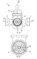
- the Fig. 7 shows a perspective view of a housing part of a second embodiment of a valve according to the invention.
- the 8A to 8C show a side, front and top view of the in Fig. 7 perspective housing part shown.
- the Fig. 9 shows a cross-sectional view of the embodiment along the section line AA of in Fig. 8B shown housing part.
- the same reference numerals used for the second embodiment denote like components.
- the valve comprises a supply line forming the pipe section 4 and one of them vertically outgoing and fluidly connected to the pipe section 4 connected first part 28 of the line section 7, in the outgoing direction an end portion 30 follows.
- the first part 28 and the end portion 30 form the line section 7.
- the first part 28 of the line section 7 projects perpendicularly from the pipe section 4 and comprises a second part 29 projecting perpendicularly from this first part 28 and comprising the connection means 8 for connecting an outlet fitting, not shown, via a connection line 24 provided for this purpose.
- the end portion 30 adjoins the outgoing from the pipe section 4 first part 28 directly and receives a valve operating element 34 surrounding the cover member 39.
- the valve operating element 34 protrudes from the cover element 39 to the outside of the housing and is outside the housing in the transition region to the cover member 39, for example, equipped with a Sich ceremoniesssplint 44 such as a Sich ceremoniesssplint.
- the in Fig. 9 shown pipe section 4 comprises a cross-sectional constriction 9 with two of the cross-sectional constriction 9 upstream or downstream Aus- or Einfädelöticianen 5 and 10.
- the pipe section 4 is symmetrical: the main flow direction H can in the illustration of Fig. 11 running from left to right as well as from right to left.
- the two openings 5 and 10 have both the function of a one and a Ausfädelö réelle, depending on the present flow direction.
- the inlet and outlet openings 5 and 10 have the same opening diameter.
- the Ausfädel- and Einfädelö réelle 5, 10 each communicate with a provided in the first part 28 of the line section 7 first and second flow holes 12, 22, which are arranged parallel to each other and separated by a partition 45 from each other.
- the first part 28 merges into the end section 30, wherein the partition wall 45 ends in the region of the transition to the end section 30.
- a movable valve element 32, 33 is provided as a component of a double shut-off valve 31 arranged in the line section.
- the Fig. 9 shows in particular a closed position of Doppelabsperrventils 31.
- the valve elements 32, 33 protrude into the inlet or Ausfädelö réelleen 5 and 10 in such a way that the end faces of the valve elements 32, 33 terminate preferably plan with an inner wall of the pipe section 4.
- the valve elements 32, 33 are surrounded by a first and second sealing ring 46, 47, wherein the first sealing ring 46 in one of the Ausfädel- or Einfädelö réelle 5, 10 near region of the valve elements 32, 33 and the second sealing ring 47 in a central region of Valve elements 32, 33 are provided to seal the first and second flow bore 12, 22 relative to the pipe section 4 sealing.
- the valve elements 32, 33 are connected at their end remote from the pipe section 4 via a plate 37 with each other.
- the plate 37 has a centered spindle guide 35 which cooperates with a spindle-shaped shaft part 41 of a valve member 34 associated rotary member 38 such that upon rotation of the rotary member 38, the plate 37 in the direction of the pipe section 4 or in the direction of the rotary member 38 becomes.
- the valve elements 32, 33 are moved in the direction of movement of the plate 37 due to their connection with the plate 37, whereby the line section 7 is either shut off or opened.
- the plate 37 has an outer diameter equal to the inner diameter of the end portion 30.
- the plate 37 In a closed position of the double shut-off valve 31, the plate 37 preferably comes into contact with an end face of the dividing wall 45 facing away from the pipe section 4 such that the displacement of the plate 37 in the direction of the pipe section 4 is limited.
- the end portion 30 receives the lid member 39, wherein the lid member 39 is screwed into the end portion 30.
- the cover element 39 comprises a centered bore, through which a head part 40 of the rotary part 38 projects to the housing outside of the fitting.
- the head part 40 comprises an annular recess in the region of the cover outer side contact surface and receives a securing pin 44.
- the head part 40 merges via a collar 42 into the shaft part 41.
- the collar 42 has a larger diameter than the head part 40 and abuts against the inside of the cover element 39. With the collar 42 and the Sich ceremoniesssplint 44 an axial displacement of the rotary member 38 is prevented.
- the Fig. 10 shows a sectional view of the second embodiment along the section line BB of the Fig. 8C shown housing part.
- the Fig. 11 shows an enlarged sectional view of the in Fig. 10 shown embodiment.
- the first and second flow holes 12, 22 via a in the second part 29 of the line section 7 respectively to these flow holes 12, 22 perpendicular and tapered to each other flow through holes 12, 22 in a formed in the second part 29 bore 23 ends.
- the bore 23 surrounds an inliner 48 which protrudes with its one end into the mouth of the second flow bore 22 communicating with the inlet or outlet opening 10 and protrudes with its other end out of the second part 29 of the line section 7.
- the protruding portion of the liner 48 is preferably coaxial with the bore 23, with the bore 23 having a larger inner diameter than an outer diameter of the liner 48.
- the second part 29 of the line section 7 has the outside formed as a connection means 8 external thread on, via which a connecting line 24 can be connected.
- the connection means 8 need not necessarily be realized via a threaded engagement.
- connecting means further known to the expert serving as a line connection means can be used.
- the bore 23 is sealed in the region of the connecting means 8 via a sealing element 49, the sealing element 49 having a centered bore which surrounds the section of the inliner 48 protruding from the line section 7.
- the sealing element 49 comprises at least one further bore 56, via which the areas surrounding the inliner 48 on both sides of the sealing element 49, in other words the area surrounding the inliner 48 in the bore 23 and the area surrounding the inliner 48 within the connecting line 24, with each other get connected.
- FIGS. 5A to 6B show a cross-sectional view along the section lines AA and BB of in Fig. 2B shown first embodiment with a closure body.
- the 12 to 14 show a cross-sectional view taken along section line AA of FIG Fig. 8B shown second embodiment with a closure body.
- the closure body is arranged in the respective cross-sectional constriction of the pipe section. Since the remaining components are of identical design and have the same function or effect, reference is made to the above-described first and second embodiments with a view to the other components. Like reference numerals also designate like components.
- the Fig. 5A to 6B and 12 show the closure body 43 in a closed position, ie, in a non-deflected position at a prevailing in the pipe section 4 volume flow Q, which is smaller than a critical volume flow Q crit .
- the critical volume flow Q crit corresponds in particular to a volume flow value at which the closure body 43 is located just in the middle in the cross-sectional constriction 9. In this centric position, only a minimal free cross-section between closure body 43 and cross-sectional constriction 9 is present. This minimal free cross section can also be achieved by a non-sealing contact between closure body 43 and cross-sectional constriction 9.
- closure body 43 shifts, as in particular for the second embodiment in FIGS. 13 and 14 shown such that a flow passage between the Closure body 43 and an inner wall of the cross-sectional constriction 9 is possible.
- the closure body according to the first embodiment shifts accordingly.
- the closure body 43 is rotationally elliptical.
- the main axis of the rotary ellipse lies on a direction of flow H of the pipe section 4 extending symmetry axis of the cross-sectional constriction 9, along which the closure body 43 is displaceable.
- the closure body 43 has an inner diameter of the cross-sectional constriction 9 almost identical maximum diameter, so that the closure body 43 almost closes the cross-sectional constriction 9 in its closed position.
- a diameter of the closure body 43 extending in the direction of flow H of the tube section 4 is essentially freely selectable, but preferably such that the closure body 43 extends in the flow direction H over a region of the cross-sectional constriction 9 into the regions of the cross-sectional enlargements adjoining the constriction 9.
- respective ends of the closure body 43 engages at least one return spring, not shown.
- the points of engagement of the return springs are preferably in the horizontal axis of rotation of the closure body 43. The other ends of the return spring are firmly connected to the pipe section 4.
- the fixing of the return springs on the pipe section is preferably carried out in one of the input and Ausfädelö réelle 5, 10 upstream or downstream region, so in the Ausfädelö réelle 5 (or 10) leading or one of the Einfädelö réelle 10 (or 5) coming Flow does not hinder.
- FIGS. 13 and 14 In particular, a deflection of the closure body 43 of the fitting according to the invention according to the second embodiment in the flow direction H of the pipe section 4 is shown. A deflection of the closure body 43 of the valve according to the invention according to the first embodiment is carried out accordingly and is therefore not described in detail, in particular with regard to the first embodiment.
- the deflection shown is achievable with a volume flow Q greater than Q crit , so that a volume flow Q introduced into the pipe section 4 can be discharged, on the one hand, into the fitting and, on the other hand, can be guided past the closure body 43.
- the return springs acting on the closure body 43 experience such a deflection that, when the volume flow Q decreases, the closure body 43 correspondingly moves in the direction its starting position is retrieved.
- return springs preferably tensile and / or compression springs are used.
- any number of return springs may be provided in any arrangement in the fitting as long as the closure body 43 is substantially along the flow direction H from a home position such as the closed position in a deflection position and back is movable.
- the shape of the closure body 43 is also not limited to an ellipsoidal shape, but the closure body 43 may also have a parabolic or circular or a different than closure body 43 suitable cross-section.
- the diameter of the closure body 43 can also be adapted to the respective circumstances.
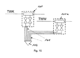
- the Fig. 15 shows a connection example of the fitting according to the invention according to at least one of the above-described embodiments.
- the fitting 100 according to the invention is connected to a drinking water cold line TWK and connects them via a formed as a pipe-in-pipe connection line 101 with an outlet fitting 102.
- a further inventive valve 100a is connected, via a prescribed connection line 101 connects the valve 100a with the same outlet fitting 102.
Landscapes
- Engineering & Computer Science (AREA)
- General Engineering & Computer Science (AREA)
- Life Sciences & Earth Sciences (AREA)
- Water Supply & Treatment (AREA)
- Public Health (AREA)
- Hydrology & Water Resources (AREA)
- Mechanical Engineering (AREA)
- Health & Medical Sciences (AREA)
- Combustion & Propulsion (AREA)
- Physics & Mathematics (AREA)
- Chemical & Material Sciences (AREA)
- Thermal Sciences (AREA)
- Valve Housings (AREA)
- Devices For Dispensing Beverages (AREA)
- Lift Valve (AREA)
- Sliding Valves (AREA)
Priority Applications (1)
| Application Number | Priority Date | Filing Date | Title |
|---|---|---|---|
| EP20140174458 EP2787260A1 (fr) | 2009-01-08 | 2009-12-29 | Armature |
Applications Claiming Priority (1)
| Application Number | Priority Date | Filing Date | Title |
|---|---|---|---|
| DE200920000180 DE202009000180U1 (de) | 2009-01-08 | 2009-01-08 | Armatur |
Related Child Applications (2)
| Application Number | Title | Priority Date | Filing Date |
|---|---|---|---|
| EP20140174458 Division-Into EP2787260A1 (fr) | 2009-01-08 | 2009-12-29 | Armature |
| EP20140174458 Division EP2787260A1 (fr) | 2009-01-08 | 2009-12-29 | Armature |
Publications (2)
| Publication Number | Publication Date |
|---|---|
| EP2206939A1 true EP2206939A1 (fr) | 2010-07-14 |
| EP2206939B1 EP2206939B1 (fr) | 2014-11-19 |
Family
ID=42060716
Family Applications (2)
| Application Number | Title | Priority Date | Filing Date |
|---|---|---|---|
| EP20090016102 Not-in-force EP2206939B1 (fr) | 2009-01-08 | 2009-12-29 | Armature |
| EP20140174458 Withdrawn EP2787260A1 (fr) | 2009-01-08 | 2009-12-29 | Armature |
Family Applications After (1)
| Application Number | Title | Priority Date | Filing Date |
|---|---|---|---|
| EP20140174458 Withdrawn EP2787260A1 (fr) | 2009-01-08 | 2009-12-29 | Armature |
Country Status (3)
| Country | Link |
|---|---|
| EP (2) | EP2206939B1 (fr) |
| DE (1) | DE202009000180U1 (fr) |
| DK (1) | DK2206939T3 (fr) |
Families Citing this family (3)
| Publication number | Priority date | Publication date | Assignee | Title |
|---|---|---|---|---|
| DE202013100710U1 (de) | 2013-02-18 | 2013-04-03 | Schell Gmbh & Co. Kg | Vorrichtung zum Anschließen einer Waschtisch-Armatur an mindestens ein Eckventil |
| DE202013100712U1 (de) | 2013-02-18 | 2013-04-03 | Schell Gmbh & Co. Kg | Armatur |
| DE102013101591B4 (de) | 2013-02-18 | 2016-12-15 | Schell Gmbh & Co. Kg | Eckventil |
Citations (6)
| Publication number | Priority date | Publication date | Assignee | Title |
|---|---|---|---|---|
| DE9411814U1 (de) * | 1994-07-01 | 1994-11-03 | Fürst, Gerhard, 78224 Singen | Installationsvorrichtung |
| EP0708209A1 (fr) * | 1994-09-13 | 1996-04-24 | Bwt Aktiengesellschaft | Assortiment d'armatures tubulaires pour les techniques relatives aux conduites d'eau, aux installations sanitaires, conduites de chauffage, de gaz etc |
| DE202006011360U1 (de) * | 2006-07-24 | 2007-11-29 | Gebr. Kemper Gmbh & Co. Kg Metallwerke | Anschlussarmatur |
| DE202008003044U1 (de) * | 2008-03-04 | 2008-05-08 | Gebr. Kemper Gmbh + Co. Kg | Anschlussarmatur |
| DE202007009832U1 (de) * | 2007-07-12 | 2008-11-13 | Gebr. Kemper Gmbh & Co. Kg Metallwerke | Anschlussarmatur |
| WO2009060285A1 (fr) * | 2007-11-07 | 2009-05-14 | Georg Fischer Llc | Système de distribution d'eau à pureté élevée |
-
2009
- 2009-01-08 DE DE200920000180 patent/DE202009000180U1/de not_active Expired - Lifetime
- 2009-12-29 EP EP20090016102 patent/EP2206939B1/fr not_active Not-in-force
- 2009-12-29 EP EP20140174458 patent/EP2787260A1/fr not_active Withdrawn
- 2009-12-29 DK DK09016102T patent/DK2206939T3/en active
Patent Citations (6)
| Publication number | Priority date | Publication date | Assignee | Title |
|---|---|---|---|---|
| DE9411814U1 (de) * | 1994-07-01 | 1994-11-03 | Fürst, Gerhard, 78224 Singen | Installationsvorrichtung |
| EP0708209A1 (fr) * | 1994-09-13 | 1996-04-24 | Bwt Aktiengesellschaft | Assortiment d'armatures tubulaires pour les techniques relatives aux conduites d'eau, aux installations sanitaires, conduites de chauffage, de gaz etc |
| DE202006011360U1 (de) * | 2006-07-24 | 2007-11-29 | Gebr. Kemper Gmbh & Co. Kg Metallwerke | Anschlussarmatur |
| DE202007009832U1 (de) * | 2007-07-12 | 2008-11-13 | Gebr. Kemper Gmbh & Co. Kg Metallwerke | Anschlussarmatur |
| WO2009060285A1 (fr) * | 2007-11-07 | 2009-05-14 | Georg Fischer Llc | Système de distribution d'eau à pureté élevée |
| DE202008003044U1 (de) * | 2008-03-04 | 2008-05-08 | Gebr. Kemper Gmbh + Co. Kg | Anschlussarmatur |
Also Published As
| Publication number | Publication date |
|---|---|
| EP2206939B1 (fr) | 2014-11-19 |
| EP2787260A1 (fr) | 2014-10-08 |
| DK2206939T3 (en) | 2015-02-02 |
| DE202009000180U1 (de) | 2010-05-20 |
Similar Documents
| Publication | Publication Date | Title |
|---|---|---|
| EP0025595B1 (fr) | Valve mélangeuse | |
| EP2098647B1 (fr) | Armature de connection | |
| EP3755927B1 (fr) | Soupape à disque en céramique | |
| DE60123112T2 (de) | Strömungsmischer | |
| DE202017100423U1 (de) | Schlauchanschlussanordnung, Verwendung einer Schlauchanschlussanordnung und Sanitärarmatur | |
| WO2018130422A1 (fr) | Vanne-pilote axiale pour assurer la commande du débit volumique dans une conduite de gaz | |
| DE102017101566B3 (de) | Schlauchanschlussanordnung, Verwendung einer Schlauchanschlussanordnung und Sanitärarmatur | |
| EP2206939B1 (fr) | Armature | |
| EP2068222A2 (fr) | Réducteur de pression | |
| DE19812049B4 (de) | Flüssigkeitsventil | |
| DE102013101591B4 (de) | Eckventil | |
| EP1213519B1 (fr) | Soupape de radiateur | |
| DE4101955C2 (de) | Sanitärarmatur | |
| DE2020075A1 (de) | Mischventil,insbesondere fuer Wasser und Wasserdampf | |
| EP2644788A1 (fr) | Agencement de séparation de tuyaux | |
| DE102010023574A1 (de) | Eckventil | |
| DE102017104332B3 (de) | Sanitäre Aufputz-Mischbatterie | |
| DE10211533B4 (de) | Hahnblock | |
| EP2644789B1 (fr) | Ensemble modulaire d'un agencement de séparation de tuyaux | |
| DE10202560A1 (de) | Thermostat-Mischventil | |
| EP2149729A1 (fr) | Vanne à boisseau sphérique dotée d'une connexion en T | |
| EP0527313B1 (fr) | Robinetterie pour conduits d'eau | |
| DE102004043659B4 (de) | Einlochmischbatterie | |
| DE2426473A1 (de) | Ventil | |
| DE60204386T2 (de) | Vorrichtung zur Durchflussteuerung in einem hydraulischen Verteiler |
Legal Events
| Date | Code | Title | Description |
|---|---|---|---|
| PUAI | Public reference made under article 153(3) epc to a published international application that has entered the european phase |
Free format text: ORIGINAL CODE: 0009012 |
|
| AK | Designated contracting states |
Kind code of ref document: A1 Designated state(s): AT BE BG CH CY CZ DE DK EE ES FI FR GB GR HR HU IE IS IT LI LT LU LV MC MK MT NL NO PL PT RO SE SI SK SM TR |
|
| AX | Request for extension of the european patent |
Extension state: AL BA RS |
|
| 17P | Request for examination filed |
Effective date: 20110113 |
|
| REG | Reference to a national code |
Ref country code: DE Ref legal event code: R079 Ref document number: 502009010238 Country of ref document: DE Free format text: PREVIOUS MAIN CLASS: F16K0021020000 Ipc: E03B0007040000 |
|
| GRAP | Despatch of communication of intention to grant a patent |
Free format text: ORIGINAL CODE: EPIDOSNIGR1 |
|
| RIC1 | Information provided on ipc code assigned before grant |
Ipc: E03B 7/04 20060101AFI20140502BHEP Ipc: F16K 21/02 20060101ALI20140502BHEP Ipc: F16K 27/10 20060101ALI20140502BHEP Ipc: E03B 7/09 20060101ALI20140502BHEP Ipc: E03C 1/02 20060101ALI20140502BHEP Ipc: F24D 17/00 20060101ALI20140502BHEP |
|
| INTG | Intention to grant announced |
Effective date: 20140606 |
|
| GRAS | Grant fee paid |
Free format text: ORIGINAL CODE: EPIDOSNIGR3 |
|
| GRAA | (expected) grant |
Free format text: ORIGINAL CODE: 0009210 |
|
| AK | Designated contracting states |
Kind code of ref document: B1 Designated state(s): AT BE BG CH CY CZ DE DK EE ES FI FR GB GR HR HU IE IS IT LI LT LU LV MC MK MT NL NO PL PT RO SE SI SK SM TR |
|
| REG | Reference to a national code |
Ref country code: GB Ref legal event code: FG4D Free format text: NOT ENGLISH |
|
| REG | Reference to a national code |
Ref country code: CH Ref legal event code: NV Representative=s name: BOVARD AG, CH Ref country code: CH Ref legal event code: EP |
|
| REG | Reference to a national code |
Ref country code: AT Ref legal event code: REF Ref document number: 697137 Country of ref document: AT Kind code of ref document: T Effective date: 20141215 |
|
| REG | Reference to a national code |
Ref country code: IE Ref legal event code: FG4D Free format text: LANGUAGE OF EP DOCUMENT: GERMAN |
|
| REG | Reference to a national code |
Ref country code: DE Ref legal event code: R096 Ref document number: 502009010238 Country of ref document: DE Effective date: 20141231 |
|
| REG | Reference to a national code |
Ref country code: SE Ref legal event code: TRGR |
|
| REG | Reference to a national code |
Ref country code: NL Ref legal event code: T3 |
|
| REG | Reference to a national code |
Ref country code: DK Ref legal event code: T3 Effective date: 20150129 |
|
| REG | Reference to a national code |
Ref country code: NO Ref legal event code: T2 Effective date: 20141119 |
|
| REG | Reference to a national code |
Ref country code: LT Ref legal event code: MG4D |
|
| PG25 | Lapsed in a contracting state [announced via postgrant information from national office to epo] |
Ref country code: PT Free format text: LAPSE BECAUSE OF FAILURE TO SUBMIT A TRANSLATION OF THE DESCRIPTION OR TO PAY THE FEE WITHIN THE PRESCRIBED TIME-LIMIT Effective date: 20150319 Ref country code: IS Free format text: LAPSE BECAUSE OF FAILURE TO SUBMIT A TRANSLATION OF THE DESCRIPTION OR TO PAY THE FEE WITHIN THE PRESCRIBED TIME-LIMIT Effective date: 20150319 Ref country code: LT Free format text: LAPSE BECAUSE OF FAILURE TO SUBMIT A TRANSLATION OF THE DESCRIPTION OR TO PAY THE FEE WITHIN THE PRESCRIBED TIME-LIMIT Effective date: 20141119 Ref country code: FI Free format text: LAPSE BECAUSE OF FAILURE TO SUBMIT A TRANSLATION OF THE DESCRIPTION OR TO PAY THE FEE WITHIN THE PRESCRIBED TIME-LIMIT Effective date: 20141119 Ref country code: ES Free format text: LAPSE BECAUSE OF FAILURE TO SUBMIT A TRANSLATION OF THE DESCRIPTION OR TO PAY THE FEE WITHIN THE PRESCRIBED TIME-LIMIT Effective date: 20141119 |
|
| PG25 | Lapsed in a contracting state [announced via postgrant information from national office to epo] |
Ref country code: GR Free format text: LAPSE BECAUSE OF FAILURE TO SUBMIT A TRANSLATION OF THE DESCRIPTION OR TO PAY THE FEE WITHIN THE PRESCRIBED TIME-LIMIT Effective date: 20150220 Ref country code: HR Free format text: LAPSE BECAUSE OF FAILURE TO SUBMIT A TRANSLATION OF THE DESCRIPTION OR TO PAY THE FEE WITHIN THE PRESCRIBED TIME-LIMIT Effective date: 20141119 Ref country code: CY Free format text: LAPSE BECAUSE OF FAILURE TO SUBMIT A TRANSLATION OF THE DESCRIPTION OR TO PAY THE FEE WITHIN THE PRESCRIBED TIME-LIMIT Effective date: 20141119 Ref country code: PL Free format text: LAPSE BECAUSE OF FAILURE TO SUBMIT A TRANSLATION OF THE DESCRIPTION OR TO PAY THE FEE WITHIN THE PRESCRIBED TIME-LIMIT Effective date: 20141119 Ref country code: LV Free format text: LAPSE BECAUSE OF FAILURE TO SUBMIT A TRANSLATION OF THE DESCRIPTION OR TO PAY THE FEE WITHIN THE PRESCRIBED TIME-LIMIT Effective date: 20141119 |
|
| PG25 | Lapsed in a contracting state [announced via postgrant information from national office to epo] |
Ref country code: RO Free format text: LAPSE BECAUSE OF FAILURE TO SUBMIT A TRANSLATION OF THE DESCRIPTION OR TO PAY THE FEE WITHIN THE PRESCRIBED TIME-LIMIT Effective date: 20141119 Ref country code: EE Free format text: LAPSE BECAUSE OF FAILURE TO SUBMIT A TRANSLATION OF THE DESCRIPTION OR TO PAY THE FEE WITHIN THE PRESCRIBED TIME-LIMIT Effective date: 20141119 Ref country code: SK Free format text: LAPSE BECAUSE OF FAILURE TO SUBMIT A TRANSLATION OF THE DESCRIPTION OR TO PAY THE FEE WITHIN THE PRESCRIBED TIME-LIMIT Effective date: 20141119 |
|
| REG | Reference to a national code |
Ref country code: DE Ref legal event code: R097 Ref document number: 502009010238 Country of ref document: DE |
|
| PG25 | Lapsed in a contracting state [announced via postgrant information from national office to epo] |
Ref country code: MC Free format text: LAPSE BECAUSE OF FAILURE TO SUBMIT A TRANSLATION OF THE DESCRIPTION OR TO PAY THE FEE WITHIN THE PRESCRIBED TIME-LIMIT Effective date: 20141119 |
|
| PLBE | No opposition filed within time limit |
Free format text: ORIGINAL CODE: 0009261 |
|
| REG | Reference to a national code |
Ref country code: FR Ref legal event code: ST Effective date: 20150831 |
|
| STAA | Information on the status of an ep patent application or granted ep patent |
Free format text: STATUS: NO OPPOSITION FILED WITHIN TIME LIMIT |
|
| 26N | No opposition filed |
Effective date: 20150820 |
|
| PG25 | Lapsed in a contracting state [announced via postgrant information from national office to epo] |
Ref country code: FR Free format text: LAPSE BECAUSE OF NON-PAYMENT OF DUE FEES Effective date: 20150119 |
|
| PG25 | Lapsed in a contracting state [announced via postgrant information from national office to epo] |
Ref country code: IT Free format text: LAPSE BECAUSE OF FAILURE TO SUBMIT A TRANSLATION OF THE DESCRIPTION OR TO PAY THE FEE WITHIN THE PRESCRIBED TIME-LIMIT Effective date: 20141119 |
|
| PG25 | Lapsed in a contracting state [announced via postgrant information from national office to epo] |
Ref country code: SI Free format text: LAPSE BECAUSE OF FAILURE TO SUBMIT A TRANSLATION OF THE DESCRIPTION OR TO PAY THE FEE WITHIN THE PRESCRIBED TIME-LIMIT Effective date: 20141119 |
|
| PG25 | Lapsed in a contracting state [announced via postgrant information from national office to epo] |
Ref country code: SM Free format text: LAPSE BECAUSE OF FAILURE TO SUBMIT A TRANSLATION OF THE DESCRIPTION OR TO PAY THE FEE WITHIN THE PRESCRIBED TIME-LIMIT Effective date: 20141119 |
|
| PG25 | Lapsed in a contracting state [announced via postgrant information from national office to epo] |
Ref country code: BG Free format text: LAPSE BECAUSE OF FAILURE TO SUBMIT A TRANSLATION OF THE DESCRIPTION OR TO PAY THE FEE WITHIN THE PRESCRIBED TIME-LIMIT Effective date: 20141119 |
|
| PG25 | Lapsed in a contracting state [announced via postgrant information from national office to epo] |
Ref country code: TR Free format text: LAPSE BECAUSE OF FAILURE TO SUBMIT A TRANSLATION OF THE DESCRIPTION OR TO PAY THE FEE WITHIN THE PRESCRIBED TIME-LIMIT Effective date: 20141119 Ref country code: HU Free format text: LAPSE BECAUSE OF FAILURE TO SUBMIT A TRANSLATION OF THE DESCRIPTION OR TO PAY THE FEE WITHIN THE PRESCRIBED TIME-LIMIT; INVALID AB INITIO Effective date: 20091229 Ref country code: MT Free format text: LAPSE BECAUSE OF FAILURE TO SUBMIT A TRANSLATION OF THE DESCRIPTION OR TO PAY THE FEE WITHIN THE PRESCRIBED TIME-LIMIT Effective date: 20141119 |
|
| PGFP | Annual fee paid to national office [announced via postgrant information from national office to epo] |
Ref country code: DK Payment date: 20161222 Year of fee payment: 8 Ref country code: LU Payment date: 20161222 Year of fee payment: 8 Ref country code: CZ Payment date: 20161129 Year of fee payment: 8 Ref country code: IE Payment date: 20161220 Year of fee payment: 8 Ref country code: GB Payment date: 20161222 Year of fee payment: 8 Ref country code: NL Payment date: 20161222 Year of fee payment: 8 |
|
| PGFP | Annual fee paid to national office [announced via postgrant information from national office to epo] |
Ref country code: SE Payment date: 20161222 Year of fee payment: 8 Ref country code: BE Payment date: 20161215 Year of fee payment: 8 |
|
| PGFP | Annual fee paid to national office [announced via postgrant information from national office to epo] |
Ref country code: NO Payment date: 20161229 Year of fee payment: 8 |
|
| PGFP | Annual fee paid to national office [announced via postgrant information from national office to epo] |
Ref country code: CH Payment date: 20171221 Year of fee payment: 9 Ref country code: AT Payment date: 20171221 Year of fee payment: 9 |
|
| PGFP | Annual fee paid to national office [announced via postgrant information from national office to epo] |
Ref country code: DE Payment date: 20171220 Year of fee payment: 9 |
|
| PG25 | Lapsed in a contracting state [announced via postgrant information from national office to epo] |
Ref country code: MK Free format text: LAPSE BECAUSE OF FAILURE TO SUBMIT A TRANSLATION OF THE DESCRIPTION OR TO PAY THE FEE WITHIN THE PRESCRIBED TIME-LIMIT Effective date: 20141119 |
|
| REG | Reference to a national code |
Ref country code: NO Ref legal event code: MMEP |
|
| REG | Reference to a national code |
Ref country code: DK Ref legal event code: EBP Effective date: 20171231 |
|
| REG | Reference to a national code |
Ref country code: NL Ref legal event code: MM Effective date: 20180101 |
|
| GBPC | Gb: european patent ceased through non-payment of renewal fee |
Effective date: 20171229 |
|
| PG25 | Lapsed in a contracting state [announced via postgrant information from national office to epo] |
Ref country code: SE Free format text: LAPSE BECAUSE OF NON-PAYMENT OF DUE FEES Effective date: 20171230 |
|
| REG | Reference to a national code |
Ref country code: IE Ref legal event code: MM4A |
|
| PG25 | Lapsed in a contracting state [announced via postgrant information from national office to epo] |
Ref country code: LU Free format text: LAPSE BECAUSE OF NON-PAYMENT OF DUE FEES Effective date: 20171229 Ref country code: NL Free format text: LAPSE BECAUSE OF NON-PAYMENT OF DUE FEES Effective date: 20180101 |
|
| REG | Reference to a national code |
Ref country code: BE Ref legal event code: MM Effective date: 20171231 |
|
| PG25 | Lapsed in a contracting state [announced via postgrant information from national office to epo] |
Ref country code: IE Free format text: LAPSE BECAUSE OF NON-PAYMENT OF DUE FEES Effective date: 20171229 Ref country code: NO Free format text: LAPSE BECAUSE OF NON-PAYMENT OF DUE FEES Effective date: 20171231 |
|
| PG25 | Lapsed in a contracting state [announced via postgrant information from national office to epo] |
Ref country code: BE Free format text: LAPSE BECAUSE OF NON-PAYMENT OF DUE FEES Effective date: 20171231 Ref country code: GB Free format text: LAPSE BECAUSE OF NON-PAYMENT OF DUE FEES Effective date: 20171229 Ref country code: CZ Free format text: LAPSE BECAUSE OF NON-PAYMENT OF DUE FEES Effective date: 20171229 |
|
| PG25 | Lapsed in a contracting state [announced via postgrant information from national office to epo] |
Ref country code: DK Free format text: LAPSE BECAUSE OF NON-PAYMENT OF DUE FEES Effective date: 20171231 |
|
| REG | Reference to a national code |
Ref country code: DE Ref legal event code: R119 Ref document number: 502009010238 Country of ref document: DE |
|
| REG | Reference to a national code |
Ref country code: CH Ref legal event code: PL |
|
| REG | Reference to a national code |
Ref country code: AT Ref legal event code: MM01 Ref document number: 697137 Country of ref document: AT Kind code of ref document: T Effective date: 20181229 |
|
| PG25 | Lapsed in a contracting state [announced via postgrant information from national office to epo] |
Ref country code: DE Free format text: LAPSE BECAUSE OF NON-PAYMENT OF DUE FEES Effective date: 20190702 |
|
| PG25 | Lapsed in a contracting state [announced via postgrant information from national office to epo] |
Ref country code: CH Free format text: LAPSE BECAUSE OF NON-PAYMENT OF DUE FEES Effective date: 20181231 Ref country code: LI Free format text: LAPSE BECAUSE OF NON-PAYMENT OF DUE FEES Effective date: 20181231 Ref country code: AT Free format text: LAPSE BECAUSE OF NON-PAYMENT OF DUE FEES Effective date: 20181229 |