EP2206919A1 - Variable capacity compressor - Google Patents
Variable capacity compressor Download PDFInfo
- Publication number
- EP2206919A1 EP2206919A1 EP08840162A EP08840162A EP2206919A1 EP 2206919 A1 EP2206919 A1 EP 2206919A1 EP 08840162 A EP08840162 A EP 08840162A EP 08840162 A EP08840162 A EP 08840162A EP 2206919 A1 EP2206919 A1 EP 2206919A1
- Authority
- EP
- European Patent Office
- Prior art keywords
- opening area
- flow passage
- valve body
- opening
- variable displacement
- Prior art date
- Legal status (The legal status is an assumption and is not a legal conclusion. Google has not performed a legal analysis and makes no representation as to the accuracy of the status listed.)
- Granted
Links
- 238000006073 displacement reaction Methods 0.000 claims abstract description 62
- 230000003247 decreasing effect Effects 0.000 claims abstract description 34
- 230000007423 decrease Effects 0.000 claims description 14
- 238000005057 refrigeration Methods 0.000 claims description 8
- 238000004378 air conditioning Methods 0.000 claims description 7
- 239000011347 resin Substances 0.000 claims description 7
- 229920005989 resin Polymers 0.000 claims description 7
- 239000007788 liquid Substances 0.000 abstract description 17
- 230000006835 compression Effects 0.000 abstract description 10
- 238000007906 compression Methods 0.000 abstract description 10
- 230000004043 responsiveness Effects 0.000 abstract description 5
- 239000003507 refrigerant Substances 0.000 description 21
- 230000002093 peripheral effect Effects 0.000 description 7
- 230000004044 response Effects 0.000 description 4
- 230000001934 delay Effects 0.000 description 3
- 230000001133 acceleration Effects 0.000 description 2
- 230000002411 adverse Effects 0.000 description 2
- 238000010586 diagram Methods 0.000 description 2
- 238000010248 power generation Methods 0.000 description 2
- 230000000694 effects Effects 0.000 description 1
- 239000012530 fluid Substances 0.000 description 1
- 238000007789 sealing Methods 0.000 description 1
Images




Classifications
-
- F—MECHANICAL ENGINEERING; LIGHTING; HEATING; WEAPONS; BLASTING
- F04—POSITIVE - DISPLACEMENT MACHINES FOR LIQUIDS; PUMPS FOR LIQUIDS OR ELASTIC FLUIDS
- F04B—POSITIVE-DISPLACEMENT MACHINES FOR LIQUIDS; PUMPS
- F04B27/00—Multi-cylinder pumps specially adapted for elastic fluids and characterised by number or arrangement of cylinders
- F04B27/08—Multi-cylinder pumps specially adapted for elastic fluids and characterised by number or arrangement of cylinders having cylinders coaxial with, or parallel or inclined to, main shaft axis
- F04B27/14—Control
- F04B27/16—Control of pumps with stationary cylinders
- F04B27/18—Control of pumps with stationary cylinders by varying the relative positions of a swash plate and a cylinder block
- F04B27/1804—Controlled by crankcase pressure
-
- F—MECHANICAL ENGINEERING; LIGHTING; HEATING; WEAPONS; BLASTING
- F04—POSITIVE - DISPLACEMENT MACHINES FOR LIQUIDS; PUMPS FOR LIQUIDS OR ELASTIC FLUIDS
- F04B—POSITIVE-DISPLACEMENT MACHINES FOR LIQUIDS; PUMPS
- F04B27/00—Multi-cylinder pumps specially adapted for elastic fluids and characterised by number or arrangement of cylinders
- F04B27/08—Multi-cylinder pumps specially adapted for elastic fluids and characterised by number or arrangement of cylinders having cylinders coaxial with, or parallel or inclined to, main shaft axis
- F04B27/10—Multi-cylinder pumps specially adapted for elastic fluids and characterised by number or arrangement of cylinders having cylinders coaxial with, or parallel or inclined to, main shaft axis having stationary cylinders
- F04B27/1009—Distribution members
-
- F—MECHANICAL ENGINEERING; LIGHTING; HEATING; WEAPONS; BLASTING
- F04—POSITIVE - DISPLACEMENT MACHINES FOR LIQUIDS; PUMPS FOR LIQUIDS OR ELASTIC FLUIDS
- F04B—POSITIVE-DISPLACEMENT MACHINES FOR LIQUIDS; PUMPS
- F04B49/00—Control, e.g. of pump delivery, or pump pressure of, or safety measures for, machines, pumps, or pumping installations, not otherwise provided for, or of interest apart from, groups F04B1/00 - F04B47/00
- F04B49/22—Control, e.g. of pump delivery, or pump pressure of, or safety measures for, machines, pumps, or pumping installations, not otherwise provided for, or of interest apart from, groups F04B1/00 - F04B47/00 by means of valves
- F04B49/225—Control, e.g. of pump delivery, or pump pressure of, or safety measures for, machines, pumps, or pumping installations, not otherwise provided for, or of interest apart from, groups F04B1/00 - F04B47/00 by means of valves with throttling valves or valves varying the pump inlet opening or the outlet opening
-
- F—MECHANICAL ENGINEERING; LIGHTING; HEATING; WEAPONS; BLASTING
- F04—POSITIVE - DISPLACEMENT MACHINES FOR LIQUIDS; PUMPS FOR LIQUIDS OR ELASTIC FLUIDS
- F04B—POSITIVE-DISPLACEMENT MACHINES FOR LIQUIDS; PUMPS
- F04B27/00—Multi-cylinder pumps specially adapted for elastic fluids and characterised by number or arrangement of cylinders
- F04B27/08—Multi-cylinder pumps specially adapted for elastic fluids and characterised by number or arrangement of cylinders having cylinders coaxial with, or parallel or inclined to, main shaft axis
- F04B27/14—Control
- F04B27/16—Control of pumps with stationary cylinders
- F04B27/18—Control of pumps with stationary cylinders by varying the relative positions of a swash plate and a cylinder block
- F04B27/1804—Controlled by crankcase pressure
- F04B2027/1863—Controlled by crankcase pressure with an auxiliary valve, controlled by
- F04B2027/1881—Suction pressure
Definitions
- An opening-degree adjustment valve which variably controls an opening area of a flow passage and which is provided in a flow passage between a suction port and a suction hole communicating with a cylinder bore, of a compressor of an air conditioning system for vehicles, etc., such as shown in Fig. 6 , is known.
- symbol 100 implies an opening-degree adjustment valve
- opening-degree adjustment valve 100 having casing 101 and valve body 102 is provided in a flow passage, which is also called a suction passage, between a suction port of a compressor and a suction hole of a cylinder bore, where casing 101 is disposed in the suction passage and valve body 102 is contained in casing 101 movably.
- Casing 101 is formed in a shape of a cylinder having the bottom, and small opening section 103 and large opening section 104 are formed on a side surface of casing 101. Further, by spring 105 which is provided in casing 101, valve body 102 is urged in a direction of shutting opening 104, which means a direction of decreasing an opening area of the flow passage. Furthermore, even in a condition where valve body 102 is urged by spring 105 in the direction of decreasing the opening area of the flow passage, small opening section 103 is always opened without closing.
- valve body 102 is pushed downward in Fig. 6 , or in a direction of increasing the opening area of large opening section 104, and the opening area of the flow passage increases.
- valve body 102 is pushed upward in Fig. 6 , or in a direction of decreasing the opening area of large opening section 104, by the bias force of spring 105.
- valve body 102 moves, because a gap is formed between valve body 102 and inner peripheral surface 101a of casing 101 so that refrigerant is flowed from communication path 107 into space 106 and flowed out therefrom, the resonance movement of valve body 102 comes to be restrained.
- opening-degree adjustment valve 100 keeps an opening-degree which makes a differential pressure through opening-degree adjustment valve 100 be nearly constant. Therefore, when there exists liquid refrigerant in an evaporator of the air conditioning system for vehicle at the compressor startup, etc., it may be caused that opening-degree adjustment valve 100 operates as the compressor starts up so as to rapidly increase the opening area of the flow passage and the liquid refrigerant in the evaporator flows into the compressor at once, causing the liquid compression, so as to adversely affect the compressor. Further, a torque limiter might operate when a compressor is a clutchless compressor.
- the movement to control the displacement of the compressor delays it can be given that even if the refrigerant flow rate of the compressor increases when the engine rotation speed increases, because of the great volume of the refrigerant in the evaporator, the inner pressure fluctuation in the evaporator can be restrained and the suction pressure decrease also becomes slow. Furthermore, it can be also given as a reason why the movement to control the displacement of the compressor delays, that during a middle-low load operation, the discharge pressure decreases and the refrigerant flow rate from a discharge chamber for controlling the displacement decreases, so that the inner pressure increase in a crank chamber slows.
- an object of the present invention is to provide a variable displacement compressor of which durability and reliability has been improved by preventing from a liquid compression at the time of the compressor startup, etc., and which can perform a superior response in controlling the displacement.
- the resistance against the movement of the valve body in the direction of increasing the opening area of the flow passage is made to be greater than the resistance against the movement in the direction of decreasing the opening area, even if there exists liquid refrigerant at the compressor startup, etc., an inconvenience that the liquid refrigerant is sucked into the compressor at once is prevented, so that the liquid compression can be surely prevented.
- the resistance through the opening-degree adjustment valve is greater in the direction of increasing the opening area of the flow passage, the pressure loss in a downstream site increases when the engine rotation speed increases. Therefore, because the differential pressure between the internal pressure of the crank chamber and the internal pressure of the suction chamber increases, the discharge displacement can decrease quickly to decrease an excessive power generation, so that the response of the displacement control can be improved.
- the above-described opening-degree adjustment valve comprises a casing placed in the flow passage and a valve body which is provided movably relative to the casing and which is urged by a spring in the direction of decreasing the opening area.
- the valve body when the opening area of the flow passage increases, the valve body is moved in the direction of increasing the opening area of the flow passage against the spring which urges in the direction of decreasing the opening area of the flow passage. And when the valve body is moved in the direction of decreasing the opening area of the flow passage, the valve body is quickly moved by the spring. Therefore, the resistance against the movement of the valve body in the direction of increasing the opening area of the flow passage can be easily made greater than the resistance against the movement in the direction of decreasing the opening area.
- a space of which volume is varied by the casing and the valve body in accordance with an increase / decrease of the opening area of the flow passage is formed in the opening-degree adjustment valve.
- a communication path capable of communicating between the space and the flow passage positioned outside the space and a valve mechanism which closes the communication path when the opening area is increased and which opens the communication path when the opening area is decreased are provided.
- the valve body can be provided slidably relative to the casing. In this case, it is sufficient that a sliding resistance of the valve body for a direction of increasing the opening area of the flow passage is made to be greater than a sliding resistance of the valve body for a direction of decreasing the opening area.
- the sliding resistance can be adjusted, for example, by interposing a sliding member between the valve body and the casing.
- a sliding member a ring-shaped resin member extending in a circumferential direction of the valve body or a lip-shaped rubber member extending in a circumferential direction of the valve body can be employed, for example.
- the opening-degree adjustment valve is formed to be a valve having a function for throttling to narrow down the flow passage, which means a suction passage, a suction pulse generated from a vibration of the suction valve transmitted to an evaporator, etc. can be reduced by the function for throttling of the suction passage.
- variable displacement compressor because the resistance against the movement of the valve body of the opening-degree adjustment valve in the direction of increasing the opening area of the flow passage is greater than the resistance against the movement in the direction of decreasing the opening area at the compressor startup, etc., an inconvenience that the liquid refrigerant in the evaporator in the refrigeration circuit is sucked into the compressor at once is prevented, so that the liquid compression can be surely prevented.
- the resistance through the opening-degree adjustment valve is greater in the direction of increasing the opening area of the flow passage, when the rotation speed of the engine as a drive source of the compressor increases, the pressure loss in a downstream site of the opening-degree adjustment valve increases and the displacement decreases quickly. Therefore, the excess power generation can be reduced and the response of the displacement control can be improved.
- variable displacement compressor 1 shows a variable displacement compressor according to the first embodiment of the present invention.
- variable displacement compressors in the embodiments to be described are composed as variable displacement compressors used for a refrigeration circuit of air conditioning system for vehicles.
- variable displacement compressor 1 has front housing 2, cylinder block 3 and cylinder head 4.
- Crank chamber 5 is formed between front housing 2 and cylinder block 3.
- Plural cylinder bores 6 are provided along a circumferential direction.
- Piston 7 is inserted reciprocably in each cylinder bore 6.
- Swash plate 9 contacts slidably with one end of piston 7 through a pair of shoes 8.
- Swash plate 9 of which inclination angle is provided to be variable is coupled with rotor 11 which rotates integrally with drive shaft 12 through hinge mechanism 10.
- a stroke of piston 7 is altered by changing the inclination angle of swash plate 9, so that the discharge displacement of the compressor is changed.
- drive shaft 12 is supported rotatably by radial bearing 13 fixed to cylinder block 3.
- displacement control valve 14 which controls the discharge displacement is provided in cylinder block 3.
- Clutch mechanism 15 is provided at the other end of drive shaft 12, and the driving force from an engine, which is not shown, is transmitted to drive shaft 12 or interrupted therefrom, in accordance with ON/OFF of clutch mechanism 15, respectively.
- Valve plate 19 is provided between cylinder block 3 and cylinder head 4, and suction hole 20 corresponding to each cylinder bore 6 and discharge hole 21 are bored on valve plate 19.
- Small opening section 30 and large opening section 31 are provided in casing 26 of opening-degree adjustment valve 25. And valve body 28 is urged by spring 27 in a direction of closing large opening section 31, which means a direction of decreasing the opening area of flow passage 24. Further, even in a condition where valve body 28 is urged in a direction of decreasing an opening area of flow passage 24 by spring 27, small opening section 30 is always opened without closing.
- opening-degree adjustment valve 25 space 32 whose volume is altered in accordance with the increase and decrease of the opening area of flow passage 24 is formed with casing 26 and valve body 28. Space 32 is communicated with a flow passage outside the space through communication path 33 provided at the bottom of casing 26. Valve mechanism 34 is provided in communication path 33.
- opening-degree adjustment valve 25 when refrigerant is sucked through suction valve 20 into cylinder bore 6 and the pressure at the downstream site of opening-degree adjustment valve 25 decreases, valve body 28 is moved downward in Fig. 2 against the biasing force of spring 27, so that the opening area of large opening section 32 increases and the opening area of flow passage 24 increases.
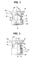
- Fig. 3 shows opening-degree adjustment valve 35 of a variable displacement compressor according to the second embodiment of the present invention.
- valve body 28 is provided slidably with respect to casing 26, and the sliding resistance of valve body 28 is greater in the direction of increasing the opening area of flow passage 24 than that in the direction of decreasing the opening area thereof.
- groove 36 extending along the circumferential direction on the external surface of valve body 28 is formed, and ring-shaped resin member 37 is fitted into groove 36. The sliding resistance of valve body 28 can be controlled by ring-shaped resin member 37.
- Ring-shaped resin member 37 is fitted into groove 36 as protruding its bottom end toward the side of inner peripheral surface 26b of casing 26 as shown in Fig. 3 .
- the sliding resistance of valve body 28 is greater in the direction of increasing the opening area of flow passage 24 than that in the direction of decreasing the opening area.
- this embodiment can be combined with the first embodiment. Such a combination makes it possible to prevent the liquid compression more efficiently and to improve the displacement control responsiveness further in a case of the increase of the engine rotational speed.
- Fig. 4 shows opening-degree adjustment valve 38 of a variable displacement compressor according to the third embodiment of the present invention.
- valve body 28 is provided slidably with respect to casing 26, and the sliding resistance of valve body 28 is greater in the direction of increasing the opening area of flow passage 24 than that in the direction of decreasing the opening area thereof.
- groove 36 extending along the circumferential direction on the external surface of valve body 28 is formed, and lip-shaped rubber member 39 is fitted into groove 36. The sliding resistance of valve body 28 can be controlled by lip-shaped rubber member 39.
- this embodiment can be combined with the first embodiment. Such a combination makes it possible to prevent the liquid compression more efficiently and to improve the displacement control responsiveness further at the increase of the engine rotational speed.
- variable displacement compressor according to the present invention is applicable to a variable displacement compressor having an opening-degree adjustment valve, and is specifically suitable as a variable displacement compressor provided in an refrigeration circuit of an air conditioning system for vehicles.
Landscapes
- Engineering & Computer Science (AREA)
- Mechanical Engineering (AREA)
- General Engineering & Computer Science (AREA)
- Compressors, Vaccum Pumps And Other Relevant Systems (AREA)
- Compressor (AREA)
- Control Of Positive-Displacement Pumps (AREA)
- Applications Or Details Of Rotary Compressors (AREA)
Abstract
Description
- The present invention relates to a variable displacement compressor having an opening-degree adjustment valve which variably controls an opening area of a flow passage, which is also called a suction passage, in the flow passage between a suction port and a suction hole communicating with a cylinder bore, and specifically, relates to a variable displacement compressor which is suitable as a compressor provided in a refrigeration circuit of an air conditioning system for vehicles.
- An opening-degree adjustment valve which variably controls an opening area of a flow passage and which is provided in a flow passage between a suction port and a suction hole communicating with a cylinder bore, of a compressor of an air conditioning system for vehicles, etc., such as shown in
Fig. 6 , is known. InFig. 6 ,symbol 100 implies an opening-degree adjustment valve, and opening-degree adjustment valve 100 havingcasing 101 andvalve body 102 is provided in a flow passage, which is also called a suction passage, between a suction port of a compressor and a suction hole of a cylinder bore, wherecasing 101 is disposed in the suction passage andvalve body 102 is contained incasing 101 movably.Casing 101 is formed in a shape of a cylinder having the bottom, andsmall opening section 103 andlarge opening section 104 are formed on a side surface ofcasing 101. Further, byspring 105 which is provided incasing 101,valve body 102 is urged in a direction of shutting opening 104, which means a direction of decreasing an opening area of the flow passage. Furthermore, even in a condition wherevalve body 102 is urged byspring 105 in the direction of decreasing the opening area of the flow passage,small opening section 103 is always opened without closing. - In such opening-
degree adjustment valve 100, because gas in a suction chamber is sucked into the cylinder bore at the time of the compressor startup, etc., the pressure in the suction chamber decreases, andvalve body 102 is pushed downward inFig. 6 , or in a direction of increasing the opening area of largeopening section 104, and the opening area of the flow passage increases. On the other hand, when a fluid sucked from a suction port side is decreased at the time of the compressor shutdown, etc.,valve body 102 is pushed upward inFig. 6 , or in a direction of decreasing the opening area of largeopening section 104, by the bias force ofspring 105. In addition,space 106 of which volume is varied bycasing 101 andvalve body 102 asvalve body 102 moves is provided in opening-degree adjustment valve 100, andspace 106 communicates with flow passages other than the space throughcommunication path 107. Whenvalve body 102 moves, because a gap is formed betweenvalve body 102 and innerperipheral surface 101a ofcasing 101 so that refrigerant is flowed fromcommunication path 107 intospace 106 and flowed out therefrom, the resonance movement ofvalve body 102 comes to be restrained. - However, opening-
degree adjustment valve 100 keeps an opening-degree which makes a differential pressure through opening-degree adjustment valve 100 be nearly constant. Therefore, when there exists liquid refrigerant in an evaporator of the air conditioning system for vehicle at the compressor startup, etc., it may be caused that opening-degree adjustment valve 100 operates as the compressor starts up so as to rapidly increase the opening area of the flow passage and the liquid refrigerant in the evaporator flows into the compressor at once, causing the liquid compression, so as to adversely affect the compressor. Further, a torque limiter might operate when a compressor is a clutchless compressor. - Furthermore, when the rotation speed of an engine as a drive source of the compressor increases as a vehicle runs, the discharge displacement of the variable displacement compressor increases temporarily. Until the discharge displacement has been controlled to decrease, especially in a case where the movement to control the displacement delays, the refrigerant flow rate is increased by the amount multiplied by the engine rotation speed increase and the discharge displacement, so that the power consumption increases. Therefore, there might be a bad influence on an engine control and an acceleration performance of the vehicle. As a reason why the movement to control the displacement of the compressor delays, it can be given that even if the refrigerant flow rate of the compressor increases when the engine rotation speed increases, because of the great volume of the refrigerant in the evaporator, the inner pressure fluctuation in the evaporator can be restrained and the suction pressure decrease also becomes slow. Furthermore, it can be also given as a reason why the movement to control the displacement of the compressor delays, that during a middle-low load operation, the discharge pressure decreases and the refrigerant flow rate from a discharge chamber for controlling the displacement decreases, so that the inner pressure increase in a crank chamber slows.
- Patent document 1:
JP-2001-289177-A - Accordingly, an object of the present invention is to provide a variable displacement compressor of which durability and reliability has been improved by preventing from a liquid compression at the time of the compressor startup, etc., and which can perform a superior response in controlling the displacement.
- To achieve the above-described object, a variable displacement compressor according to the present invention is a variable displacement compressor comprising an opening-degree adjustment valve, which is provided in a flow passage between a suction port and a suction hole communicating with a cylinder bore, to variably control an opening area of the flow passage, characterized in that a resistance against a movement of a valve body of the opening-degree adjustment valve in a direction of increasing the opening area of the flow passage is made to be greater than a resistance against a movement in a direction of decreasing the opening area.
- In the present invention, because the resistance against the movement of the valve body in the direction of increasing the opening area of the flow passage is made to be greater than the resistance against the movement in the direction of decreasing the opening area, even if there exists liquid refrigerant at the compressor startup, etc., an inconvenience that the liquid refrigerant is sucked into the compressor at once is prevented, so that the liquid compression can be surely prevented. In addition, because the resistance through the opening-degree adjustment valve is greater in the direction of increasing the opening area of the flow passage, the pressure loss in a downstream site increases when the engine rotation speed increases. Therefore, because the differential pressure between the internal pressure of the crank chamber and the internal pressure of the suction chamber increases, the discharge displacement can decrease quickly to decrease an excessive power generation, so that the response of the displacement control can be improved.
- It is possible that the above-described opening-degree adjustment valve comprises a casing placed in the flow passage and a valve body which is provided movably relative to the casing and which is urged by a spring in the direction of decreasing the opening area. In such a composition, when the opening area of the flow passage increases, the valve body is moved in the direction of increasing the opening area of the flow passage against the spring which urges in the direction of decreasing the opening area of the flow passage. And when the valve body is moved in the direction of decreasing the opening area of the flow passage, the valve body is quickly moved by the spring. Therefore, the resistance against the movement of the valve body in the direction of increasing the opening area of the flow passage can be easily made greater than the resistance against the movement in the direction of decreasing the opening area.
- It is preferable that a space of which volume is varied by the casing and the valve body in accordance with an increase / decrease of the opening area of the flow passage is formed in the opening-degree adjustment valve. And, it is preferable that a communication path capable of communicating between the space and the flow passage positioned outside the space and a valve mechanism which closes the communication path when the opening area is increased and which opens the communication path when the opening area is decreased are provided. In such a structure, when the opening area of the flow passage is decreased, because the communication path is opened by the valve mechanism and refrigerant is flowed into the space, the valve body can be moved quickly in a direction of decreasing the opening area of the flow passage.
- The valve body can be provided slidably relative to the casing. In this case, it is sufficient that a sliding resistance of the valve body for a direction of increasing the opening area of the flow passage is made to be greater than a sliding resistance of the valve body for a direction of decreasing the opening area.
- The sliding resistance can be adjusted, for example, by interposing a sliding member between the valve body and the casing. As the sliding member, a ring-shaped resin member extending in a circumferential direction of the valve body or a lip-shaped rubber member extending in a circumferential direction of the valve body can be employed, for example.
- If the opening-degree adjustment valve is formed to be a valve having a function for throttling to narrow down the flow passage, which means a suction passage, a suction pulse generated from a vibration of the suction valve transmitted to an evaporator, etc. can be reduced by the function for throttling of the suction passage.
- Such a structure of the opening-degree adjustment valve in the variable displacement compressor according to the present invention is applicable to every variable displacement compressor provided with this kind of opening-degree adjustment valve. Specifically, it is suitable as a variable displacement compressor which is provided in a refrigeration circuit of an air conditioning system for vehicles, and which requires to prevent from a delay of the movement for controlling the displacement of a compressor which might adversely affect on the control of an engine as a drive source of the compressor and on a acceleration performance of a vehicle.
- In the variable displacement compressor according to the present invention, because the resistance against the movement of the valve body of the opening-degree adjustment valve in the direction of increasing the opening area of the flow passage is greater than the resistance against the movement in the direction of decreasing the opening area at the compressor startup, etc., an inconvenience that the liquid refrigerant in the evaporator in the refrigeration circuit is sucked into the compressor at once is prevented, so that the liquid compression can be surely prevented. In addition, because the resistance through the opening-degree adjustment valve is greater in the direction of increasing the opening area of the flow passage, when the rotation speed of the engine as a drive source of the compressor increases, the pressure loss in a downstream site of the opening-degree adjustment valve increases and the displacement decreases quickly. Therefore, the excess power generation can be reduced and the response of the displacement control can be improved.
-
- [
Fig. 1] Fig. 1 is a vertical sectional view of a variable displacement compressor according to the first embodiment of the present invention. - [
Fig. 2] Fig. 2 is an enlarged sectional view of an opening-degree adjustment valve of the variable displacement compressor inFig. 1 . - [
Fig. 3] Fig. 3 is an enlarged sectional view of an opening-degree adjustment valve according to the second embodiment of the present invention. - [
Fig. 4] Fig. 4 is an enlarged sectional view of an opening-degree adjustment valve according to the third embodiment of the present invention. - [
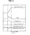
Fig. 5] Fig. 5 is a characteristic diagram, showing compressor power, shaft torque, pressure in the crank chamber and the suction pressure change when the engine rotational speed increased for the variable displacement compressor shown inFig. 1 . - [
Fig. 6] Fig. 6 is an enlarged sectional view of a opening-degree adjustment valve of a conventional variable displacement compressor. - [
Fig. 7] Fig. 7 is a characteristic diagram, showing compressor power, shaft torque, pressure in the crank chamber and the suction pressure change when the engine rotational speed increases for the variable displacement compressor shown inFig. 6 . -
- 1:
- variable displacement compressor
- 2:
- front housing
- 3:
- cylinder block
- 4:
- cylinder head
- 5:
- crank chamber
- 6:
- cylinder bore
- 7:
- piston
- 8:
- shoe
- 9:
- swash plate
- 10:
- hinge mechanism
- 11:
- rotor
- 12:
- drive shaft
- 13:
- radial bearing
- 14:
- displacement control valve
- 15:
- clutch mechanism
- 16:
- inner wall
- 17:
- suction chamber
- 18:
- discharge chamber
- 19:
- valve plate
- 20:
- suction hole
- 21:
- discharge hole
- 22:
- suction port
- 23:
- discharge port
- 24:
- flow passage from suction port to suction hole
- 25, 35, 38
- opening-degree adjustment valve
- 26:
- casing
- 26a:
- brim section of casing
- 26b:
- inner peripheral surface of casing
- 27:
- spring
- 28:
- valve body
- 29:
- groove
- 30:
- small opening section
- 31:
- large opening section
- 32:
- space
- 33:
- communication path
- 34:
- valve mechanism
- 36:
- groove
- 37:
- ring-shaped resin member
- 39:
- lip-shaped rubber member
- Hereinafter, desirable embodiments of a variable displacement compressor according to the present invention will be explained referring to figures.
Fig. 1 shows a variable displacement compressor according to the first embodiment of the present invention. Besides, variable displacement compressors in the embodiments to be described are composed as variable displacement compressors used for a refrigeration circuit of air conditioning system for vehicles. InFig. 1 ,variable displacement compressor 1 has front housing 2,cylinder block 3 and cylinder head 4. Crank chamber 5 is formed between front housing 2 andcylinder block 3. Plural cylinder bores 6 are provided along a circumferential direction. Piston 7 is inserted reciprocably in each cylinder bore 6.Swash plate 9 contacts slidably with one end of piston 7 through a pair of shoes 8.Swash plate 9 of which inclination angle is provided to be variable is coupled withrotor 11 which rotates integrally withdrive shaft 12 throughhinge mechanism 10. A stroke of piston 7 is altered by changing the inclination angle ofswash plate 9, so that the discharge displacement of the compressor is changed. - One end of
drive shaft 12 is supported rotatably byradial bearing 13 fixed tocylinder block 3. In addition,displacement control valve 14 which controls the discharge displacement is provided incylinder block 3.Clutch mechanism 15 is provided at the other end ofdrive shaft 12, and the driving force from an engine, which is not shown, is transmitted to driveshaft 12 or interrupted therefrom, in accordance with ON/OFF ofclutch mechanism 15, respectively. - Inside of cylinder head 4 is sectioned into suction chamber 17 and
discharge chamber 18 byinner wall 16.Valve plate 19 is provided betweencylinder block 3 and cylinder head 4, andsuction hole 20 corresponding to each cylinder bore 6 and dischargehole 21 are bored onvalve plate 19. - Refrigerant sucked from
suction port 22 connected to the low pressure side of the refrigeration circuit into suction chamber 17 is sucked into cylinder bore 6 throughsuction hole 20, and the refrigerant which has been compressed in cylinder bore 6 by reciprocation movement of piston 7 is discharged intodischarge chamber 18 throughdischarge hole 21.Discharge port 23 is communicated withdischarge chamber 18, and dischargeport 23 is connected to the high pressure side of the refrigeration circuit. - In
flow passage 24 which extends fromsuction port 22 via suction chamber 17 tosuction hole 20, opening-degree adjustment valve 25 which controls the opening area offlow passage 24 is provided. As shown inFig. 2 , opening-degree adjustment valve 25 hascasing 26 andvalve body 28, wherecasing 26 is disposed inflow passage 24 at the bottom end ofsuction port 20 in this embodiment andvalve body 28 is provided movably with respect to casing 26 and urged in a direction of decreasing the opening area offlow passage 24 byspring 27. In this embodiment,brim section 26a ofcasing 26 is fitted intogroove 29 provided at the bottom end ofsuction port 22. -
Small opening section 30 andlarge opening section 31 are provided incasing 26 of opening-degree adjustment valve 25. Andvalve body 28 is urged byspring 27 in a direction of closinglarge opening section 31, which means a direction of decreasing the opening area offlow passage 24. Further, even in a condition wherevalve body 28 is urged in a direction of decreasing an opening area offlow passage 24 byspring 27,small opening section 30 is always opened without closing. - Furthermore, in opening-
degree adjustment valve 25,space 32 whose volume is altered in accordance with the increase and decrease of the opening area offlow passage 24 is formed withcasing 26 andvalve body 28.Space 32 is communicated with a flow passage outside the space throughcommunication path 33 provided at the bottom ofcasing 26.Valve mechanism 34 is provided incommunication path 33. In opening-degree adjustment valve 25, when refrigerant is sucked throughsuction valve 20 into cylinder bore 6 and the pressure at the downstream site of opening-degree adjustment valve 25 decreases,valve body 28 is moved downward inFig. 2 against the biasing force ofspring 27, so that the opening area oflarge opening section 32 increases and the opening area offlow passage 24 increases. In this state, thoughcommunication path 33 is closed byvalve mechanism 34, refrigerant in space is permitted to discharge from a gap, betweenvalve body 28 andinner surface 26b ofcasing 26. However, becausecommunication path 33 is closed byvalve mechanism 34, the discharge speed of refrigerant inspace 32 becomes slow, and the resistance against the increase of the opening area offlow passage 24 increases. On the other hand, when the suction pressure of refrigerant falls,valve body 28 is moved upward inFig. 2 by the spring force ofspring 27, so that the opening area oflarge opening section 32 decreases and the opening area offlow passage 24 decreases. And whenvalve body 28 is moved in a direction of decreasing the opening area offlow passage 24,communication path 33 is opened byvalve mechanism 34 andspace 32 is communicated with other flow passages, so that the refrigerant is flowed intospace 32. Therefore, by the force ofspring 27 and refrigerant which is flowed intospace 32,valve body 28 is moved in a direction of decreasing the opening area offlow passage 24 immediately. In other words, the resistance against the movement ofvalve body 28 in the direction of increasing the opening area offlow passage 24 is greater than the resistance against the movement in the direction of decreasing the opening area offlow passage 24. - In this embodiment, because the resistance against the movement of
valve body 28 in the direction of increasing the opening area offlow passage 24 is greater than the resistance against the movement in the direction of decreasing the opening area, even if there exists liquid refrigerant in the evaporator at the compressor startup, etc., such an inconvenience that the liquid refrigerant is sucked at once into the compressor is prevented and the liquid compression can be surely prevented. In addition, the resistance through opening-degree adjustment valve 25 in the direction of increasing the opening area offlow passage 24 is greater. Therefore as shown inFig. 5 , because the pressure loss at the downstream site of opening-degree adjustment valve 25 increases when the engine rotation speed increases, in a variable displacement compressor of which the differential pressure between the inner pressure of the crank chamber and suction pressure is controlled so as to keep nearly constant, the differential pressure increases and the discharge displacement is reduced immediately. Therefore, the generation of excessive power can be reduced and the response to control the displacement can be improved. -
Fig. 3 shows opening-degree adjustment valve 35 of a variable displacement compressor according to the second embodiment of the present invention. Besides, because opening-degree adjustment valve 25 in the first embodiment is the same as opening-degree adjustment valve 35 as to an essential structure, the explanation will be omitted by giving the same number to the same member. In this embodiment,valve body 28 is provided slidably with respect to casing 26, and the sliding resistance ofvalve body 28 is greater in the direction of increasing the opening area offlow passage 24 than that in the direction of decreasing the opening area thereof. In this embodiment, groove 36 extending along the circumferential direction on the external surface ofvalve body 28 is formed, and ring-shapedresin member 37 is fitted intogroove 36. The sliding resistance ofvalve body 28 can be controlled by ring-shapedresin member 37. - Ring-shaped
resin member 37 is fitted intogroove 36 as protruding its bottom end toward the side of innerperipheral surface 26b of casing 26 as shown inFig. 3 . In such a structure, becausevalve body 28 slides as the bottom end of ring-shapedresin member 37 scratches the innerperipheral surface 26b ofcasing 26 whenvalve body 28 moves downward inFig. 3 , which means a direction of increasing the opening area of the flow passage, the sliding resistance ofvalve body 28 is greater in the direction of increasing the opening area offlow passage 24 than that in the direction of decreasing the opening area. - Even in this embodiment, because the resistance against the movement of
valve body 28 in the direction of increasing the opening area offlow passage 24 is greater than the resistance against the movement in the direction of decreasing the opening area, the liquid compression is prevented according to the function of the first embodiment and the displacement control responsiveness at the time of increase of the engine rotational speed can be improved. - As well, this embodiment can be combined with the first embodiment. Such a combination makes it possible to prevent the liquid compression more efficiently and to improve the displacement control responsiveness further in a case of the increase of the engine rotational speed.
-
Fig. 4 shows opening-degree adjustment valve 38 of a variable displacement compressor according to the third embodiment of the present invention. Besides, because opening-degree adjustment valve 25 in the first embodiment is the same as opening-degree adjustment valve 38 about an essential structure, the explanation will be omitted by giving the same number to the same member. In this embodiment,valve body 28 is provided slidably with respect to casing 26, and the sliding resistance ofvalve body 28 is greater in the direction of increasing the opening area offlow passage 24 than that in the direction of decreasing the opening area thereof. In this embodiment, groove 36 extending along the circumferential direction on the external surface ofvalve body 28 is formed, and lip-shapedrubber member 39 is fitted intogroove 36. The sliding resistance ofvalve body 28 can be controlled by lip-shapedrubber member 39. - Lip-shaped
rubber member 39 is fitted intogroove 36 as protruding its tip side toward the side of innerperipheral surface 26b of casing 26 as shown inFig. 4 . In such a structure, whenvalve body 28 moves downward inFig. 4 , which means a direction of increasing the opening area, a seal structure is formed between the tip of lip-shapedrubber member 39 and innerperipheral surface 26b of the casing, so that the gas inspace 32 can be discharged only fromcommunication path 33. On the other hand, when valve body moves upward inFig. 4 , which means a direction of decreasing the opening area, the sealing performance of a gap between the tip of lip-shapedrubber member 39 and innerperipheral surface 26b of the casing reduces, so that gas entersspace 32 even through the gap. Therefore, the sliding resistance ofvalve body 28 is greater in the direction of increasing the opening area offlow passage 24 than that in the direction of decreasing the opening area thereof. Even in this embodiment, because the resistance against the movement ofvalve body 28 in the direction of increasing the opening area offlow passage 24 is greater than the resistance against the movement in the direction of decreasing the opening area, the liquid compression is prevented according to the function of the first embodiment and the displacement control responsiveness at the time of increase of the engine rotational speed can be improved. - As well, this embodiment can be combined with the first embodiment. Such a combination makes it possible to prevent the liquid compression more efficiently and to improve the displacement control responsiveness further at the increase of the engine rotational speed.
- A variable displacement compressor according to the present invention is applicable to a variable displacement compressor having an opening-degree adjustment valve, and is specifically suitable as a variable displacement compressor provided in an refrigeration circuit of an air conditioning system for vehicles.
Claims (9)
- A variable displacement compressor comprising an opening-degree adjustment valve, which is provided in a flow passage between a suction port and a suction hole communicating with a cylinder bore, to variably control an opening area of said flow passage, characterized in that a resistance against a movement of a valve body of said opening-degree adjustment valve in a direction of increasing said opening area of said flow passage is made to be greater than a resistance against a movement in a direction of decreasing said opening area.
- The variable displacement compressor according to claim 1, wherein said opening-degree adjustment valve comprises a casing placed in said flow passage and a valve body which is provided movably relative to said casing and which is urged by a spring in said direction of decreasing said opening area.
- The variable displacement compressor according to claim 2, wherein a space of which volume is varied by said casing and said valve body in accordance with an increase / decrease of said opening area of said flow passage is formed, and a communication path capable of communicating between said space and said flow passage positioned outside said space and a valve mechanism which closes said communication path when said opening area is increased and which opens said communication path when said opening area is decreased are provided.
- The variable displacement compressor according to claim 2, wherein said valve body is provided slidably relative to said casing, and a sliding resistance of said valve body for a direction of increasing said opening area of said flow passage is made to be greater than a sliding resistance of said valve body for a direction of decreasing said opening area.
- The variable displacement compressor according to claim 4, wherein a sliding member which is capable of controlling said sliding resistance is interposed between said valve body and said casing.
- The variable displacement compressor according to claim 5, wherein said sliding member is a ring-shaped resin member extending in a circumferential direction of said valve body.
- The variable displacement compressor according to claim 5, wherein said sliding member is a lip-shaped rubber member extending in a circumferential direction of said valve body.
- The variable displacement compressor according to claim 1, wherein said opening-degree adjustment valve is a valve having a function for throttling to narrow down said flow passage.
- The variable displacement compressor according to claim 1, wherein said compressor is provided in a refrigeration cycle of an air conditioning system for vehicles.
Applications Claiming Priority (2)
| Application Number | Priority Date | Filing Date | Title |
|---|---|---|---|
| JP2007272719A JP2009102989A (en) | 2007-10-19 | 2007-10-19 | Variable displacement compressor |
| PCT/JP2008/067788 WO2009051006A1 (en) | 2007-10-19 | 2008-10-01 | Variable capacity compressor |
Publications (3)
| Publication Number | Publication Date |
|---|---|
| EP2206919A1 true EP2206919A1 (en) | 2010-07-14 |
| EP2206919A4 EP2206919A4 (en) | 2010-10-20 |
| EP2206919B1 EP2206919B1 (en) | 2012-08-01 |
Family
ID=40567279
Family Applications (1)
| Application Number | Title | Priority Date | Filing Date |
|---|---|---|---|
| EP08840162A Not-in-force EP2206919B1 (en) | 2007-10-19 | 2008-10-01 | Variable capacity compressor |
Country Status (6)
| Country | Link |
|---|---|
| US (1) | US8529219B2 (en) |
| EP (1) | EP2206919B1 (en) |
| JP (1) | JP2009102989A (en) |
| KR (1) | KR101194431B1 (en) |
| CN (1) | CN101828034A (en) |
| WO (1) | WO2009051006A1 (en) |
Families Citing this family (8)
| Publication number | Priority date | Publication date | Assignee | Title |
|---|---|---|---|---|
| KR101915968B1 (en) * | 2012-04-27 | 2018-11-07 | 한온시스템 주식회사 | Swash plate type compressor |
| KR101877258B1 (en) * | 2012-10-26 | 2018-07-11 | 한온시스템 주식회사 | Swash plate type compressor |
| KR101886726B1 (en) * | 2013-02-08 | 2018-08-09 | 한온시스템 주식회사 | Swash plate type compressor |
| WO2015033391A1 (en) | 2013-09-03 | 2015-03-12 | サンデン株式会社 | Compressor |
| WO2017115715A1 (en) * | 2015-12-28 | 2017-07-06 | 株式会社ヴァレオジャパン | Compressor |
| KR102671320B1 (en) * | 2016-08-24 | 2024-06-03 | 한온시스템 주식회사 | Suction pulsation reduction device of swash plate type compressor |
| KR102717005B1 (en) * | 2020-02-19 | 2024-10-15 | 한온시스템 주식회사 | Check valve and swash plate type compressor |
| WO2023287185A2 (en) * | 2021-07-14 | 2023-01-19 | 한온시스템 주식회사 | Variable-capacity swash plate-type compressor control method and variable-capacity swash plate-type compressor controlled thereby |
Family Cites Families (13)
| Publication number | Priority date | Publication date | Assignee | Title |
|---|---|---|---|---|
| JPS5043527A (en) * | 1973-08-22 | 1975-04-19 | ||
| JPH0422071Y2 (en) * | 1985-06-10 | 1992-05-20 | ||
| JP2812962B2 (en) * | 1988-08-31 | 1998-10-22 | カヤバ工業株式会社 | Hydraulic shock absorber |
| US5400995A (en) * | 1992-04-15 | 1995-03-28 | Hill-Rom Company, Inc. | IV pole with interior drag brake |
| JP4181274B2 (en) * | 1998-08-24 | 2008-11-12 | サンデン株式会社 | Compressor |
| DE19847342A1 (en) | 1998-10-14 | 2000-08-17 | Gkn Sinter Metals Holding Gmbh | Pistons with support webs for a piston-cylinder arrangement, in particular shock absorber pistons |
| JP3933369B2 (en) * | 2000-04-04 | 2007-06-20 | サンデン株式会社 | Piston type variable capacity compressor |
| JP4246975B2 (en) * | 2002-02-04 | 2009-04-02 | イーグル工業株式会社 | Capacity control valve |
| JP4479504B2 (en) * | 2004-04-28 | 2010-06-09 | 株式会社豊田自動織機 | Variable capacity compressor |
| JP4412184B2 (en) * | 2005-01-27 | 2010-02-10 | 株式会社豊田自動織機 | Variable capacity compressor |
| JP4706617B2 (en) * | 2006-11-03 | 2011-06-22 | 株式会社豊田自動織機 | Compressor suction throttle valve |
| JP4656044B2 (en) * | 2006-11-10 | 2011-03-23 | 株式会社豊田自動織機 | Compressor suction throttle valve |
| US8366407B2 (en) * | 2007-02-16 | 2013-02-05 | Kabushiki Kaisha Toyota Jidoshokki | Device for reducing pulsation in a variable displacement compressor |
-
2007
- 2007-10-19 JP JP2007272719A patent/JP2009102989A/en active Pending
-
2008
- 2008-10-01 KR KR1020107010345A patent/KR101194431B1/en not_active Expired - Fee Related
- 2008-10-01 EP EP08840162A patent/EP2206919B1/en not_active Not-in-force
- 2008-10-01 WO PCT/JP2008/067788 patent/WO2009051006A1/en not_active Ceased
- 2008-10-01 US US12/682,079 patent/US8529219B2/en not_active Expired - Fee Related
- 2008-10-01 CN CN200880112436A patent/CN101828034A/en active Pending
Non-Patent Citations (2)
| Title |
|---|
| No further relevant documents disclosed * |
| See also references of WO2009051006A1 * |
Also Published As
| Publication number | Publication date |
|---|---|
| EP2206919A4 (en) | 2010-10-20 |
| JP2009102989A (en) | 2009-05-14 |
| KR20100065399A (en) | 2010-06-16 |
| KR101194431B1 (en) | 2012-10-24 |
| WO2009051006A1 (en) | 2009-04-23 |
| EP2206919B1 (en) | 2012-08-01 |
| CN101828034A (en) | 2010-09-08 |
| US20100209272A1 (en) | 2010-08-19 |
| US8529219B2 (en) | 2013-09-10 |
Similar Documents
| Publication | Publication Date | Title |
|---|---|---|
| EP2206919B1 (en) | Variable capacity compressor | |
| JP4479504B2 (en) | Variable capacity compressor | |
| US8439652B2 (en) | Suction throttle valve for variable displacement type compressor | |
| EP2098727A2 (en) | Swash plate type compressor | |
| US6149401A (en) | Variable discharge-amount compressor for refrigerant cycle | |
| KR20140104300A (en) | Intake checking valve | |
| KR101607708B1 (en) | A control valve for Variable displacement swash plate type compressor | |
| JP5123715B2 (en) | Swash plate compressor | |
| JP4412186B2 (en) | Variable capacity compressor | |
| KR101099100B1 (en) | Displacement control valve of variable displacement compressor | |
| CN101503993B (en) | Swash plate compressor | |
| KR20200009554A (en) | Variable displacement swash plate type compressor | |
| KR20200009555A (en) | Variable displacement swash plate type compressor | |
| KR101763979B1 (en) | Variable displacement swash plate type compressor | |
| KR101079117B1 (en) | Variable displacement compressor | |
| KR101058774B1 (en) | Check valve of variable displacement compressor | |
| KR102080627B1 (en) | Pressure control device of crank chamber for variable swash platecompressor | |
| KR101601966B1 (en) | Variable displacement compressor | |
| JP2001193647A (en) | Reciprocating compressor | |
| KR101915969B1 (en) | Variable displacement swash plate type compressor | |
| JP2004211570A (en) | Variable displacement compressor | |
| JPH11241680A (en) | Variable displacement compressor | |
| JP2007192154A (en) | Reciprocating fluid machine | |
| KR20110072490A (en) | Capacity variable compressor | |
| KR20110021011A (en) | Capacity variable compressor |
Legal Events
| Date | Code | Title | Description |
|---|---|---|---|
| PUAI | Public reference made under article 153(3) epc to a published international application that has entered the european phase |
Free format text: ORIGINAL CODE: 0009012 |
|
| 17P | Request for examination filed |
Effective date: 20100426 |
|
| AK | Designated contracting states |
Kind code of ref document: A1 Designated state(s): AT BE BG CH CY CZ DE DK EE ES FI FR GB GR HR HU IE IS IT LI LT LU LV MC MT NL NO PL PT RO SE SI SK TR |
|
| AX | Request for extension of the european patent |
Extension state: AL BA MK RS |
|
| A4 | Supplementary search report drawn up and despatched |
Effective date: 20100921 |
|
| RIC1 | Information provided on ipc code assigned before grant |
Ipc: F04B 27/10 20060101AFI20100915BHEP Ipc: F04B 27/18 20060101ALI20100915BHEP Ipc: F04B 49/22 20060101ALI20100915BHEP |
|
| DAX | Request for extension of the european patent (deleted) | ||
| 17Q | First examination report despatched |
Effective date: 20110707 |
|
| REG | Reference to a national code |
Ref country code: DE Ref legal event code: R079 Ref document number: 602008017680 Country of ref document: DE Free format text: PREVIOUS MAIN CLASS: F04B0027080000 Ipc: F04B0027100000 |
|
| GRAP | Despatch of communication of intention to grant a patent |
Free format text: ORIGINAL CODE: EPIDOSNIGR1 |
|
| RIC1 | Information provided on ipc code assigned before grant |
Ipc: F04B 49/22 20060101ALI20120127BHEP Ipc: F04B 27/18 20060101ALI20120127BHEP Ipc: F04B 27/10 20060101AFI20120127BHEP |
|
| GRAS | Grant fee paid |
Free format text: ORIGINAL CODE: EPIDOSNIGR3 |
|
| GRAA | (expected) grant |
Free format text: ORIGINAL CODE: 0009210 |
|
| AK | Designated contracting states |
Kind code of ref document: B1 Designated state(s): AT BE BG CH CY CZ DE DK EE ES FI FR GB GR HR HU IE IS IT LI LT LU LV MC MT NL NO PL PT RO SE SI SK TR |
|
| REG | Reference to a national code |
Ref country code: GB Ref legal event code: FG4D |
|
| REG | Reference to a national code |
Ref country code: AT Ref legal event code: REF Ref document number: 568845 Country of ref document: AT Kind code of ref document: T Effective date: 20120815 Ref country code: CH Ref legal event code: EP |
|
| REG | Reference to a national code |
Ref country code: IE Ref legal event code: FG4D |
|
| REG | Reference to a national code |
Ref country code: DE Ref legal event code: R096 Ref document number: 602008017680 Country of ref document: DE Effective date: 20120927 |
|
| REG | Reference to a national code |
Ref country code: NL Ref legal event code: VDEP Effective date: 20120801 |
|
| REG | Reference to a national code |
Ref country code: AT Ref legal event code: MK05 Ref document number: 568845 Country of ref document: AT Kind code of ref document: T Effective date: 20120801 |
|
| REG | Reference to a national code |
Ref country code: LT Ref legal event code: MG4D Effective date: 20120801 |
|
| PG25 | Lapsed in a contracting state [announced via postgrant information from national office to epo] |
Ref country code: IS Free format text: LAPSE BECAUSE OF FAILURE TO SUBMIT A TRANSLATION OF THE DESCRIPTION OR TO PAY THE FEE WITHIN THE PRESCRIBED TIME-LIMIT Effective date: 20121201 Ref country code: LT Free format text: LAPSE BECAUSE OF FAILURE TO SUBMIT A TRANSLATION OF THE DESCRIPTION OR TO PAY THE FEE WITHIN THE PRESCRIBED TIME-LIMIT Effective date: 20120801 Ref country code: CY Free format text: LAPSE BECAUSE OF FAILURE TO SUBMIT A TRANSLATION OF THE DESCRIPTION OR TO PAY THE FEE WITHIN THE PRESCRIBED TIME-LIMIT Effective date: 20120801 Ref country code: NO Free format text: LAPSE BECAUSE OF FAILURE TO SUBMIT A TRANSLATION OF THE DESCRIPTION OR TO PAY THE FEE WITHIN THE PRESCRIBED TIME-LIMIT Effective date: 20121101 Ref country code: HR Free format text: LAPSE BECAUSE OF FAILURE TO SUBMIT A TRANSLATION OF THE DESCRIPTION OR TO PAY THE FEE WITHIN THE PRESCRIBED TIME-LIMIT Effective date: 20120801 Ref country code: FI Free format text: LAPSE BECAUSE OF FAILURE TO SUBMIT A TRANSLATION OF THE DESCRIPTION OR TO PAY THE FEE WITHIN THE PRESCRIBED TIME-LIMIT Effective date: 20120801 Ref country code: AT Free format text: LAPSE BECAUSE OF FAILURE TO SUBMIT A TRANSLATION OF THE DESCRIPTION OR TO PAY THE FEE WITHIN THE PRESCRIBED TIME-LIMIT Effective date: 20120801 |
|
| PG25 | Lapsed in a contracting state [announced via postgrant information from national office to epo] |
Ref country code: LV Free format text: LAPSE BECAUSE OF FAILURE TO SUBMIT A TRANSLATION OF THE DESCRIPTION OR TO PAY THE FEE WITHIN THE PRESCRIBED TIME-LIMIT Effective date: 20120801 Ref country code: SI Free format text: LAPSE BECAUSE OF FAILURE TO SUBMIT A TRANSLATION OF THE DESCRIPTION OR TO PAY THE FEE WITHIN THE PRESCRIBED TIME-LIMIT Effective date: 20120801 Ref country code: PL Free format text: LAPSE BECAUSE OF FAILURE TO SUBMIT A TRANSLATION OF THE DESCRIPTION OR TO PAY THE FEE WITHIN THE PRESCRIBED TIME-LIMIT Effective date: 20120801 Ref country code: BE Free format text: LAPSE BECAUSE OF FAILURE TO SUBMIT A TRANSLATION OF THE DESCRIPTION OR TO PAY THE FEE WITHIN THE PRESCRIBED TIME-LIMIT Effective date: 20120801 Ref country code: GR Free format text: LAPSE BECAUSE OF FAILURE TO SUBMIT A TRANSLATION OF THE DESCRIPTION OR TO PAY THE FEE WITHIN THE PRESCRIBED TIME-LIMIT Effective date: 20121102 Ref country code: SE Free format text: LAPSE BECAUSE OF FAILURE TO SUBMIT A TRANSLATION OF THE DESCRIPTION OR TO PAY THE FEE WITHIN THE PRESCRIBED TIME-LIMIT Effective date: 20120801 Ref country code: PT Free format text: LAPSE BECAUSE OF FAILURE TO SUBMIT A TRANSLATION OF THE DESCRIPTION OR TO PAY THE FEE WITHIN THE PRESCRIBED TIME-LIMIT Effective date: 20121203 |
|
| PG25 | Lapsed in a contracting state [announced via postgrant information from national office to epo] |
Ref country code: NL Free format text: LAPSE BECAUSE OF FAILURE TO SUBMIT A TRANSLATION OF THE DESCRIPTION OR TO PAY THE FEE WITHIN THE PRESCRIBED TIME-LIMIT Effective date: 20120801 |
|
| PG25 | Lapsed in a contracting state [announced via postgrant information from national office to epo] |
Ref country code: EE Free format text: LAPSE BECAUSE OF FAILURE TO SUBMIT A TRANSLATION OF THE DESCRIPTION OR TO PAY THE FEE WITHIN THE PRESCRIBED TIME-LIMIT Effective date: 20120801 Ref country code: RO Free format text: LAPSE BECAUSE OF FAILURE TO SUBMIT A TRANSLATION OF THE DESCRIPTION OR TO PAY THE FEE WITHIN THE PRESCRIBED TIME-LIMIT Effective date: 20120801 Ref country code: DK Free format text: LAPSE BECAUSE OF FAILURE TO SUBMIT A TRANSLATION OF THE DESCRIPTION OR TO PAY THE FEE WITHIN THE PRESCRIBED TIME-LIMIT Effective date: 20120801 Ref country code: ES Free format text: LAPSE BECAUSE OF FAILURE TO SUBMIT A TRANSLATION OF THE DESCRIPTION OR TO PAY THE FEE WITHIN THE PRESCRIBED TIME-LIMIT Effective date: 20121112 Ref country code: CZ Free format text: LAPSE BECAUSE OF FAILURE TO SUBMIT A TRANSLATION OF THE DESCRIPTION OR TO PAY THE FEE WITHIN THE PRESCRIBED TIME-LIMIT Effective date: 20120801 |
|
| PG25 | Lapsed in a contracting state [announced via postgrant information from national office to epo] |
Ref country code: MC Free format text: LAPSE BECAUSE OF NON-PAYMENT OF DUE FEES Effective date: 20121031 Ref country code: SK Free format text: LAPSE BECAUSE OF FAILURE TO SUBMIT A TRANSLATION OF THE DESCRIPTION OR TO PAY THE FEE WITHIN THE PRESCRIBED TIME-LIMIT Effective date: 20120801 Ref country code: IT Free format text: LAPSE BECAUSE OF FAILURE TO SUBMIT A TRANSLATION OF THE DESCRIPTION OR TO PAY THE FEE WITHIN THE PRESCRIBED TIME-LIMIT Effective date: 20120801 |
|
| REG | Reference to a national code |
Ref country code: CH Ref legal event code: PL |
|
| PLBE | No opposition filed within time limit |
Free format text: ORIGINAL CODE: 0009261 |
|
| STAA | Information on the status of an ep patent application or granted ep patent |
Free format text: STATUS: NO OPPOSITION FILED WITHIN TIME LIMIT |
|
| 26N | No opposition filed |
Effective date: 20130503 |
|
| REG | Reference to a national code |
Ref country code: IE Ref legal event code: MM4A |
|
| GBPC | Gb: european patent ceased through non-payment of renewal fee |
Effective date: 20121101 |
|
| PG25 | Lapsed in a contracting state [announced via postgrant information from national office to epo] |
Ref country code: LI Free format text: LAPSE BECAUSE OF NON-PAYMENT OF DUE FEES Effective date: 20121031 Ref country code: BG Free format text: LAPSE BECAUSE OF FAILURE TO SUBMIT A TRANSLATION OF THE DESCRIPTION OR TO PAY THE FEE WITHIN THE PRESCRIBED TIME-LIMIT Effective date: 20121101 Ref country code: CH Free format text: LAPSE BECAUSE OF NON-PAYMENT OF DUE FEES Effective date: 20121031 Ref country code: IE Free format text: LAPSE BECAUSE OF NON-PAYMENT OF DUE FEES Effective date: 20121001 |
|
| REG | Reference to a national code |
Ref country code: DE Ref legal event code: R097 Ref document number: 602008017680 Country of ref document: DE Effective date: 20130503 |
|
| PG25 | Lapsed in a contracting state [announced via postgrant information from national office to epo] |
Ref country code: GB Free format text: LAPSE BECAUSE OF NON-PAYMENT OF DUE FEES Effective date: 20121101 Ref country code: MT Free format text: LAPSE BECAUSE OF FAILURE TO SUBMIT A TRANSLATION OF THE DESCRIPTION OR TO PAY THE FEE WITHIN THE PRESCRIBED TIME-LIMIT Effective date: 20120801 |
|
| PGFP | Annual fee paid to national office [announced via postgrant information from national office to epo] |
Ref country code: FR Payment date: 20131022 Year of fee payment: 6 |
|
| PG25 | Lapsed in a contracting state [announced via postgrant information from national office to epo] |
Ref country code: TR Free format text: LAPSE BECAUSE OF FAILURE TO SUBMIT A TRANSLATION OF THE DESCRIPTION OR TO PAY THE FEE WITHIN THE PRESCRIBED TIME-LIMIT Effective date: 20120801 |
|
| PG25 | Lapsed in a contracting state [announced via postgrant information from national office to epo] |
Ref country code: LU Free format text: LAPSE BECAUSE OF NON-PAYMENT OF DUE FEES Effective date: 20121001 |
|
| PG25 | Lapsed in a contracting state [announced via postgrant information from national office to epo] |
Ref country code: HU Free format text: LAPSE BECAUSE OF FAILURE TO SUBMIT A TRANSLATION OF THE DESCRIPTION OR TO PAY THE FEE WITHIN THE PRESCRIBED TIME-LIMIT Effective date: 20081001 |
|
| REG | Reference to a national code |
Ref country code: FR Ref legal event code: ST Effective date: 20150630 |
|
| PG25 | Lapsed in a contracting state [announced via postgrant information from national office to epo] |
Ref country code: FR Free format text: LAPSE BECAUSE OF NON-PAYMENT OF DUE FEES Effective date: 20141031 |
|
| REG | Reference to a national code |
Ref country code: DE Ref legal event code: R082 Ref document number: 602008017680 Country of ref document: DE Representative=s name: PRUEFER & PARTNER MBB PATENTANWAELTE RECHTSANW, DE Ref country code: DE Ref legal event code: R081 Ref document number: 602008017680 Country of ref document: DE Owner name: SANDEN HOLDINGS CORPORATION, LSESAKI-SHI, JP Free format text: FORMER OWNER: SANDEN CORP., ISESAKI, GUNMA, JP |
|
| PGFP | Annual fee paid to national office [announced via postgrant information from national office to epo] |
Ref country code: DE Payment date: 20161020 Year of fee payment: 9 |
|
| REG | Reference to a national code |
Ref country code: DE Ref legal event code: R119 Ref document number: 602008017680 Country of ref document: DE |
|
| PG25 | Lapsed in a contracting state [announced via postgrant information from national office to epo] |
Ref country code: DE Free format text: LAPSE BECAUSE OF NON-PAYMENT OF DUE FEES Effective date: 20180501 |