EP2206912B1 - Fuel injector - Google Patents
Fuel injector Download PDFInfo
- Publication number
- EP2206912B1 EP2206912B1 EP09169850A EP09169850A EP2206912B1 EP 2206912 B1 EP2206912 B1 EP 2206912B1 EP 09169850 A EP09169850 A EP 09169850A EP 09169850 A EP09169850 A EP 09169850A EP 2206912 B1 EP2206912 B1 EP 2206912B1
- Authority
- EP
- European Patent Office
- Prior art keywords
- fuel injector
- volume
- valve element
- throttle
- fuel
- Prior art date
- Legal status (The legal status is an assumption and is not a legal conclusion. Google has not performed a legal analysis and makes no representation as to the accuracy of the status listed.)
- Not-in-force
Links
Images

Classifications
-
- F—MECHANICAL ENGINEERING; LIGHTING; HEATING; WEAPONS; BLASTING
- F02—COMBUSTION ENGINES; HOT-GAS OR COMBUSTION-PRODUCT ENGINE PLANTS
- F02M—SUPPLYING COMBUSTION ENGINES IN GENERAL WITH COMBUSTIBLE MIXTURES OR CONSTITUENTS THEREOF
- F02M47/00—Fuel-injection apparatus operated cyclically with fuel-injection valves actuated by fluid pressure
- F02M47/02—Fuel-injection apparatus operated cyclically with fuel-injection valves actuated by fluid pressure of accumulator-injector type, i.e. having fuel pressure of accumulator tending to open, and fuel pressure in other chamber tending to close, injection valves and having means for periodically releasing that closing pressure
- F02M47/027—Electrically actuated valves draining the chamber to release the closing pressure
-
- F—MECHANICAL ENGINEERING; LIGHTING; HEATING; WEAPONS; BLASTING
- F02—COMBUSTION ENGINES; HOT-GAS OR COMBUSTION-PRODUCT ENGINE PLANTS
- F02M—SUPPLYING COMBUSTION ENGINES IN GENERAL WITH COMBUSTIBLE MIXTURES OR CONSTITUENTS THEREOF
- F02M61/00—Fuel-injectors not provided for in groups F02M39/00 - F02M57/00 or F02M67/00
- F02M61/04—Fuel-injectors not provided for in groups F02M39/00 - F02M57/00 or F02M67/00 having valves, e.g. having a plurality of valves in series
- F02M61/10—Other injectors with elongated valve bodies, i.e. of needle-valve type
- F02M61/12—Other injectors with elongated valve bodies, i.e. of needle-valve type characterised by the provision of guiding or centring means for valve bodies
-
- F—MECHANICAL ENGINEERING; LIGHTING; HEATING; WEAPONS; BLASTING
- F02—COMBUSTION ENGINES; HOT-GAS OR COMBUSTION-PRODUCT ENGINE PLANTS
- F02M—SUPPLYING COMBUSTION ENGINES IN GENERAL WITH COMBUSTIBLE MIXTURES OR CONSTITUENTS THEREOF
- F02M61/00—Fuel-injectors not provided for in groups F02M39/00 - F02M57/00 or F02M67/00
- F02M61/16—Details not provided for in, or of interest apart from, the apparatus of groups F02M61/02 - F02M61/14
- F02M61/167—Means for compensating clearance or thermal expansion
-
- F—MECHANICAL ENGINEERING; LIGHTING; HEATING; WEAPONS; BLASTING
- F02—COMBUSTION ENGINES; HOT-GAS OR COMBUSTION-PRODUCT ENGINE PLANTS
- F02M—SUPPLYING COMBUSTION ENGINES IN GENERAL WITH COMBUSTIBLE MIXTURES OR CONSTITUENTS THEREOF
- F02M63/00—Other fuel-injection apparatus having pertinent characteristics not provided for in groups F02M39/00 - F02M57/00 or F02M67/00; Details, component parts, or accessories of fuel-injection apparatus, not provided for in, or of interest apart from, the apparatus of groups F02M39/00 - F02M61/00 or F02M67/00; Combination of fuel pump with other devices, e.g. lubricating oil pump
- F02M63/02—Fuel-injection apparatus having several injectors fed by a common pumping element, or having several pumping elements feeding a common injector; Fuel-injection apparatus having provisions for cutting-out pumps, pumping elements, or injectors; Fuel-injection apparatus having provisions for variably interconnecting pumping elements and injectors alternatively
- F02M63/0225—Fuel-injection apparatus having a common rail feeding several injectors ; Means for varying pressure in common rails; Pumps feeding common rails
Definitions
- the invention relates to a fuel injector, in particular a common rail injector, for injecting fuel into a combustion chamber of an internal combustion engine, according to the preamble of claim 1.
- Hub-controlled common rail injectors whose injection valve element is servo-operated are known. Piezo and solenoid valves are used as pressure actuators, with which the servo circuit is controlled. For rapid needle closure, a permanent low pressure stage is often provided which exerts a permanent, closing hydraulic force on the needle. The disadvantage is the high leakage, which occurs between the high pressure and the low pressure stage. Leakage inevitably leads to the requirement for higher pump performance and thus to sacrifice in the efficiency of the system. This situation is problematic especially at high pressures. For this reason, the latest injectors are designed leak-free for highest injection pressures.
- leak-free fuel injectors do not have a permanent low-pressure stage acting in the closing direction, which eliminates the leaks caused thereby. Due to the elimination of the low pressure stage, two-piece injection valve elements of the type that are used in practice for use fuel injectors used with low-pressure stage, no longer be used.
- Injectors of this kind are made DE 102007 001 363 A known.
- the invention has for its object to provide a simply constructed fuel injector, in which the coupling of the at least two injection valve element parts is realized with the lowest possible number of components.
- the invention is based on the idea to introduce two relatively adjustable parts of the injection valve element into one another, so as to be able to dispense with a separate guide sleeve, as used in the prior art, as well as a spring-loaded spring the spring sleeve.
- the at least, preferably exclusively two-part, construction has the advantage that the production of the individual injection valve element parts in total is less complicated and thus less expensive than the production of a one-piece long injection valve element.
- existing production lines can be maintained and the existing logistics, which is aligned with a multi-part injection valve element.
- the invention has also recognized that it would result in a solution with in-run injector element parts to a constant increase in the Kopplervolumens in operation of the fuel injector, if the coupler volume would be connected exclusively via a guide gap between the two parts with a Injektorvolumen, since the flow resistance of the guide gap is proportional to the applied pressure difference , The fact that the flow resistance of such a guide gap is linearly related to the magnitude of the pressure difference between the coupler volume and injector volume would cause much fuel to be drawn from the injector volume upon opening of the fuel injector due to the very low pressure in the coupler volume and emptying the Kopplervolumens during the closing process due to the available (short) time would no longer be possible.
- the coupler volume is additionally or alternatively connected to a guide gap via at least one throttle arrangement with the injector volume in a fuel injector designed according to the concept of the invention, wherein the throttle arrangement is designed such that the fuel volume flow flowing through it ( Flow volume flow) is not proportional to the pressure difference between the coupler volume and injector volume as a guide gap behaves, but disproportionately.
- the flow volume flow passing through the throttle assembly does not increase to the same extent as a pressure difference between the volume of the coupler and the injector volume, ie, the flow volume flow and the pressure difference are not linearly related.
- the flow volume flow increase becomes smaller and smaller with increasing pressure difference.
- the flow volume flow is proportional to the root of the pressure difference between injector volume and coupler volume.
- the throttle arrangement is to provide at least one, preferably only one, realized in particular in the first or second part, throttle bore, the throttle bore very particularly preferably in the manner of a drain throttle from a control chamber as in known servo-circuit fuel injectors is.
- the throttle bore is preferably a stepped bore with a diameter step, which preferably leads to the formation of a turbulent, cavitating flow within the throttle bore.
- the above-mentioned diameter stage is a possibility for realizing a degressive ratio between flow volume flow and pressure difference between the coupler volume and injector volume.
- any throttle stages in particular hydraulically sharp-edged throttle stages, can be realized for this purpose, preferably with a small longitudinal extension in the flow direction.
- the longitudinal extension of the at least one throttle stage is designed such that a turbulent flow is formed.
- a length to hydraulic diameter ratio is less than or equal to 10 to understand.
- the following applies to the hydraulic diameter of an annular gap reactor D Hyd 4 ⁇ effetsttr ⁇ O ⁇ ⁇ cross section throughflow ⁇ O ⁇ ⁇ m. Berandungsl ⁇ a ⁇ ⁇ nge ,
- the boundary length in this equation is the sum of the inner and the outer boundary length.
- the throttle arrangement comprises a plurality of hydraulically connected in series (arranged) throttles.
- the throttles are formed radially between the two injection valve element parts, preferably in the guide region, with which the two parts are guided into one another.
- the throttles are designed in such a way, ie have such a small extent in the flow direction, that the guide length is so small that forms a turbulent flow.
- the flow volume flow would be by the throttle arrangement proportional to the pressure difference between the coupler volume and injector volume, which should be avoided.
- One possibility for forming the throttle arrangement is to provide a plurality of axially juxtaposed (parallel) grooves on one of the injection valve element parts, wherein the throttles are formed radially between the webs delimiting the grooves and the other injection valve element part.
- the webs Preferably, the webs, at least approximately, sharp-edged to realize a minimum guide length and thus to force the formation of a turbulent flow.
- it is very particularly preferred to dispense with a throttle bore in the injection valve element parts.
- the hydraulic coupler is designed as a joint, which allows a certain pivotability of the two hydraulically coupled injection valve element parts to compensate in this way tolerance-related angular errors and inclinations.
- a particularly preferred possibility for forming such a pivot joint is to contour the guided injection valve element part in the region of the guide in order to allow a relative pivoting.
- the fuel injector is leak-free except for leaks which may have been realized in the region of the control valve element.
- a low-pressure stage acting on the injection valve element in the closing direction on the injection valve element is dispensed with.
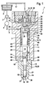
- Fig. 1 is a trained as a common rail injector fuel injector 1 for injecting fuel into a combustion chamber, not shown, also shown an internal combustion engine of a motor vehicle.
- a high pressure pump 2 delivers fuel from a reservoir 3 in a high-pressure fuel storage 4 (Rail). In this fuel, especially diesel or gasoline, under high pressure, stored in this embodiment about 2000bar.
- the fuel injector 1 is connected via other, not shown, fuel injectors via a supply line 5.
- the supply line 5 opens into an annular space 6 radially between a valve body 7 and an injector body 8 (housing part).
- the high-pressure fuel can flow essentially unthrottled in the axial direction in the plane of the drawing down into a pressure space 11 acting as a mini-rail for pressure oscillation minimization.
- the fuel flows directly through axial passages 13 into a nozzle chamber 14 (annular space) also belonging to the injector volume 12 and out of this through at least one injection hole 15 into the combustion chamber of the internal combustion engine.
- the fuel injector 1 is connected via an injector return port 16 to a return line 17. About the return line 17 can be explained later on a control amount of fuel from the fuel injector 1 to the reservoir 3 drain and be fed from there from the high pressure circuit again.
- a two-part injection valve element 18 in this exemplary embodiment is arranged to be adjustable in the axial direction.
- the injection valve element 18 projects with its lower, designed as a nozzle needle first part 19 in a stepped bore 20 of a nozzle body 21 into it.
- the first part 19 is guided axially displaceably with a guide portion 22.
- the axial channels 13 are formed by bevels 9 in the guide section 22 radially between the first part 19 and the nozzle body 21.
- the nozzle body 21 is screwed by means of a union nut, not shown, with the injector body 8.
- the first part 19 (nozzle needle) of the injection valve element 18 is guided in an end blind bore 23 of a second part 24 (control rod) of the injection valve element 18.
- the injection valve element 18 has a closing surface 26 (sealing surface) on a (lower) tip 25 formed on the first part 19, with which the injection valve element 18 can be brought into tight contact with an injection valve element seat 27 formed inside the nozzle body 21.
- the injection valve element 18 abuts against its injection valve element seat 27, ie is in a closed position, the fuel outlet from the at least one injection hole 15 is blocked. If, on the other hand, it is lifted off its injection valve element seat 27, fuel can flow from the pressure chamber 11 via the axial channels 13 and the annular chamber 14 to the injection valve element seat 27 to the injection hole 15 where it is injected substantially under high pressure (rail pressure) into the combustion chamber become.
- a control chamber 29 is limited, which extends over a radially extending in the sleeve-shaped portion of the valve body 7 inlet throttle 30 with high-pressure fuel from the Annulus 6 is supplied.
- the sleeve-shaped portion with control chamber 29 enclosed therein is enclosed radially on the outside with high-pressure fuel, so that an annular Guide gap 31 radially between the sleeve-shaped portion of the valve body 7 and the injection valve element 18, here the second part 24, is comparatively fuel-tight.
- the control chamber 29 is connected via a, extending perpendicularly in the valve body 7 axial channel 32 with outlet throttle 33 with a valve chamber 34 which radially outwardly of an axially adjustable, sleeve-shaped control valve element 35 of a pressure-balanced in the axial direction in the closed state control valve 36 (servo valve) is limited.
- fuel can flow into a low-pressure region 37 of the fuel injector 1 and thence to the injector return port 16 when the sleeve-shaped control valve element 35 is lifted from its control valve element seat 38 formed on the valve body 7, i. when the control valve 36 is open.
- an electromagnetic actuator 39 is provided with an electromagnet 40 which cooperates with an integrally formed with the control valve element 35 anchor plate 41 and subsequently with the sleeve-shaped control valve element 35.
- the electromagnetic actuator 39 raises the control valve element 35 from its formed on the valve body 7, designed in this embodiment as a flat seat control valve element seat 38 from.
- the flow cross-sections of the inlet throttle 30 and the outlet throttle 33 are matched to one another such that when open control valve 36, a net outflow of fuel (control amount) from the control chamber 29 in the low pressure region 37 of the fuel injector 1 and from there via the Injektor Weglaufan gleich 16 and Return line 17 results in the reservoir 3.
- the pressure in the control chamber 29 decreases rapidly, whereby the injection valve element 18, more precisely the first part 19, lifts off from its injection valve element seat 27 so that fuel can flow out of the injector volume 12 through the injection hole 15 into the combustion chamber.
- the energization of the electromagnetic actuator 39 is interrupted, whereby the sleeve-shaped control valve element 35 is adjusted by means of a control spring 42 which is supported on the armature plate 41 in the drawing plane down on its control valve element seat 38.
- the fuel flowing in through the inlet throttle 30 into the control chamber 29 provides for a rapid pressure increase in the control chamber 29 and thus for a force acting on the injection valve element 18 closing force.
- the resulting closing movement of the injection valve element 18 is assisted by a closing spring 43, which is supported at one end on a circumferential collar 44 of the second part 24 and at the other end on a lower, annular end side 45 of the valve body 7.
- a loose pressure pin 47 is accommodated, which is designed as a separate component from the valve body 7.
- the purpose of the cylindrical pressure pin 47 is to seal the valve chamber 34 in the axial direction in order to prevent fuel from the control chamber 29 being able to flow into the low-pressure region 37 when the control valve element 35 is closed, except for an unavoidable amount of leakage.
- the pressure pin 47 also serves to guide the control valve element 35 at its inner periphery formed by the bore 46.
- Fig. 1 results, it is in the fuel injector 1 to a so-called leak-free injector, which has no leakage except for a leak in the region of the control valve 36, since no permanent, acting on the injection valve element 18 in the closing direction low pressure stage is provided.
- the first part 19 is guided into the second part 24 of the injection valve element 18 and guided on the inner circumference of the blind hole 23.
- a hydraulic coupler volume 50 is formed, which couples the movement of the parts 19, 24. How to get out Fig. 1 results, the coupler volume 50 is hydraulically connected to the Injektorvolumen 12 via a consisting of a single throttle bore 51 throttle assembly 52.
- the pressure in the coupler volume 50 drops rapidly and the opening force is transmitted to the first part 19 due to the suction effect in the sequence of its injection valve element seat 27 lifts. Due to the aforementioned negative pressure in the coupler volume 50, this increases because fuel from the injector 12 via the throttle assembly 52 in a range between axially the end face 48 of the first part 19 and the bottom 49 of the blind hole 23 flows.
- the throttle arrangement 52 is designed such that the filling or the increase of the coupler volume 50 does not lead to any functionally relevant change in the maximum stroke of the injection valve element 18. This can also be realized in the case of a multiple injection.
- the fit between the first part 19 and the inner circumference of the blind hole 23 is dimensioned so that the volume flow occurring here compared to the flow volume flow through the throttle assembly 52 is negligible - so the guide gap 53 is to be described as substantially hydraulic tight.
- Fig. 1 is the first part 19 formed in the region of the guide gap 53 and thus formed as a pivot joint, so as to be able to compensate for angular errors and inclinations between the nozzle-side guide and the guide of the injection valve element 18 in the valve body 7.
- FIG. 2 shown embodiment of a fuel injector 1 substantially corresponds to the embodiment according to Fig. 1 , so as to avoid repetition in terms of similarities to the preceding description of the figures as well as on Fig. 1 is referenced. In the following, only differences to the preceding embodiment are explained essentially.
- a throttle bore for connecting the coupler volume 50 to the injector volume 12 has been dispensed with.
- the coupler volume 50 is also formed between the bottom 49 of the blind bore 23 and the upper side 48 in the plane of the drawing of the first part 19 of the injection valve element 18.
- the throttle arrangement 52 is realized in the region of a guide 54 between the outer circumference of the first part 19 and the inner circumference of the blind bore 23.
- the throttle arrangement 52 comprises in the exemplary embodiment shown a number of throttles 55 arranged one behind the other in the axial direction.
- the throttles 55 are each formed between an annular web 56 with a radially tapered outer edge and the inner circumference of the blind bore 23.
- the axial extent of the webs 56 in a voltage applied to the inner circumference of the blind hole 23 area is so short that can form a turbulent flow, with the result that the flow rate through the throttle assembly 52 only disproportionately increases with increasing pressure difference between the coupler volume 50 and 12 injector.
- the two adjacent in the axial direction, annular webs 56 define between them a groove 57 (circumferential groove) on the outer periphery of the first part 19.
- a groove 57 (circumferential groove) on the outer periphery of the first part 19.
- the first part 19 in the region of the guide 54 formed somewhat spherical, so that the first part 19 is pivotable relative to the second part 24 within certain limits, so that angle errors can be compensated.
Abstract
Description
Die Erfindung betrifft einen Kraftstoff-Injektor, insbesondere einen Common-Rail-Injektor, zum Einspritzen von Kraftstoff in einen Brennraum einer Brennkraftmaschine, gemäß dem Oberbegriff des Anspruchs 1.The invention relates to a fuel injector, in particular a common rail injector, for injecting fuel into a combustion chamber of an internal combustion engine, according to the preamble of claim 1.
Die Einhaltung von Schadstoffgrenzwerten hat bei der Entwicklung von Verbrennungsmotoren die höchste Priorität. Gerade das Common-Rail-Einspritzsystem hat einen entscheidenden Beitrag zur Reduzierung der Schadstoffe geleistet. Der Vorteil der Common-Rail-Systeme liegt in ihrer Unabhängigkeit des Einspritzdrucks von Drehzahl und Last. Für die Einhaltung zukünftiger Abgasgrenzwerte ist jedoch gerade bei Dieselmotoren eine signifikante Erhöhung des Einspritzdrucks notwendig.Compliance with emission limits has the highest priority in the development of internal combustion engines. Especially the common rail injection system has made a decisive contribution to the reduction of pollutants. The advantage of the common-rail systems lies in their independence of the injection pressure of speed and load. For the compliance with future exhaust emission limits, however, a significant increase of the injection pressure is necessary, especially for diesel engines.
Bekannt sind hubgesteuerte Common-Rail-Injektoren, deren Einspritzventilelement servobetrieben ist. Als Drucksteller sind Piezo- und Magnetventile im Einsatz, mit denen der Servokreislauf gesteuert wird. Zum schnellen Nadelschließen wird häufig eine dauerhafte Niederdruckstufe vorgesehen, die eine permanente, schließende hydraulische Kraft auf die Nadel ausübt. Der Nachteil ist die hohe Leckage, die sich zwischen der Hochdruck- und der Niederdruckstufe einstellt. Eine Leckage führt unweigerlich zu dem Erfordernis einer höheren Pumpenleistung und somit zu Einbußen in der Effizienz des Systems. Dieser Sachverhalt wird insbesondere bei hohen Drücken problematisch. Aus diesem Grund werden neueste Injektoren für höchste Einspritzdrücke leckagefrei ausgeführt.Hub-controlled common rail injectors whose injection valve element is servo-operated are known. Piezo and solenoid valves are used as pressure actuators, with which the servo circuit is controlled. For rapid needle closure, a permanent low pressure stage is often provided which exerts a permanent, closing hydraulic force on the needle. The disadvantage is the high leakage, which occurs between the high pressure and the low pressure stage. Leakage inevitably leads to the requirement for higher pump performance and thus to sacrifice in the efficiency of the system. This situation is problematic especially at high pressures. For this reason, the latest injectors are designed leak-free for highest injection pressures.
Im Gegensatz zu herkömmlichen Bauformen haben diese, so genannten leckagefreien, Kraftstoff-Injektoren keine dauerhafte in Schließrichtung wirkende Niederdruckstufe, wodurch die dadurch begründeten Leckagestellen entfallen. Aufgrund der wegfallenden Niederdruckstufe können zweiteilige Einspritzventilelemente in der Art, wie sie bei in der Praxis zum Einsatz kommenden Kraftstoff-Injektoren mit Niederdruckstufe eingesetzt werden, nicht mehr verwendet werden.In contrast to conventional designs, these so-called leak-free fuel injectors do not have a permanent low-pressure stage acting in the closing direction, which eliminates the leaks caused thereby. Due to the elimination of the low pressure stage, two-piece injection valve elements of the type that are used in practice for use fuel injectors used with low-pressure stage, no longer be used.
Während die beiden Einspritzventilelementteile (Steuerstange und Düsennadel) bei heutigen Serien-Injektoren mit Niederdruckstufe durch die resultierenden Druckkräfte aufeinander gedrückt werden, muss bei leckagefreien Kraftstoff-Injektoren eine separate form- oder kraftschlüssige Verbindung hergestellt werden. Zur Kopplung zweier Einspritzventilelemente ist es bekannt geworden, axial zwischen diesen ein hydraulisches Kopplervolumen vorzusehen. Dabei ist das Kopplervolumen üblicherweise in einer Kopplerhülse realisiert, in der eines der Einspritzventilelementteile geführt ist. Dabei wird das Kopplervolumen durch Herausdrücken von Kraftstoff durch den Führungsspalt zwischen dem in der Hülse geführten Einspritzventilelementteil und der Hülse verkleinert.While the two injection valve element parts (control rod and nozzle needle) are pressed in today's series injectors with low pressure stage by the resulting pressure forces on each other, a separate positive or non-positive connection must be made at leak-free fuel injectors. For the coupling of two injection valve elements, it has become known to provide a hydraulic coupler volume axially between them. In this case, the coupler volume is usually realized in a coupler sleeve in which one of the injection valve element parts is guided. In this case, the coupler volume is reduced by pushing out of fuel through the guide gap between the guided in the sleeve injection valve member part and the sleeve.
Injektoren dieser Art sind aus
Der Erfindung liegt die Aufgabe zugrunde, einen einfach aufgebauten Kraftstoff-Injektor vorzuschlagen, bei dem die Kopplung der mindestens zwei Einspritzventilelementteile mit einer möglichst geringen Bauteilzahl realisiert ist.The invention has for its object to provide a simply constructed fuel injector, in which the coupling of the at least two injection valve element parts is realized with the lowest possible number of components.
Diese Aufgabe wird mit einem Kraftstoff-Injektor mit den Merkmalen des Anspruchs 1 gelöst. Vorteilhafte Weiterbildungen der Erfindung sind in den Unteransprüchen angegeben.This object is achieved with a fuel injector having the features of claim 1. Advantageous developments of the invention are specified in the subclaims.
Der Erfindung liegt der Gedanke zugrunde, zwei relativ zueinander verstellbare Teile des Einspritzventilelementes ineinander zu führen, um somit auf eine separate Führungshülse, wie sie im Stand der Technik zum Einsatz kommt, sowie eine die Führungshülse federkraftbeaufschlagende Feder verzichten zu können. Im Gegensatz zu dem Vorsehen eines einteiligen, langen Einspritzventilelementes hat die mindestens, vorzugsweise ausschließlich zweiteilige, Ausbildung den Vorteil, dass die Fertigung der einzelnen Einspritzventilelementteile in Summe weniger aufwändig und damit kostengünstiger ist als die Fertigung eines einteiligen langen Einspritzventilelementes. Zudem können bestehende Fertigungslinien beibehalten werden sowie die bestehende Logistik, die auf ein mehrteiliges Einspritzventilelement ausgerichtet ist. Die Erfindung hat zudem erkannt, dass es bei einer Lösung mit ineinander geführten Einspritzventilelementteilen zu einer ständigen Vergrößerung des Kopplervolumens im Betrieb des Kraftstoff-Injektors kommen würde, wenn das Kopplervolumen ausschließlich über einen Führungsspalt zwischen den beiden Teilen mit einem Injektorvolumen verbunden wäre, da sich der Strömungswiderstand des Führungsspaltes proportional zur anliegenden Druckdifferenz verhält. Die Tatsache, dass der Strömungswiderstand eines derartigen Führungsspaltes in einem linearen Zusammenhang zu der Größe der Druckdifferenz zwischen Kopplervolumen und Injektorvolumen steht, würde dazu führen, dass beim Öffnen des Kraftstoff-Injektors aufgrund des sehr niedrigen Drucks im Kopplervolumen sehr viel Kraftstoff aus dem Injektorvolumen angesaugt würde und eine Entleerung des Kopplervolumens beim Schließvorgang aufgrund der zur Verfügung stehenden (kurzen) Zeit nicht mehr möglich wäre. Im Extremfall würde dies zu einer axialen Verstemmung des Einspritzventilelementes im Kraftstoff-Injektor und damit zu einem Verstellen des Kraftstoff-Injektors führen. Um einen derartigen Effekt zu vermeiden, ist das Kopplervolumen bei einem nach dem Konzept der Erfindung ausgebildeten Kraftstoff-Injektor zusätzlich oder alternativ zu einem Führungsspalt über mindestens eine Drosselanordnung mit dem Injektorvolumen verbunden, wobei die Drosselanordnung derart ausgebildet ist, dass der durch diese durchströmende Kraftstoffvolumenstrom (Durchflussvolumenstrom) sich nicht proportional zur Druckdifferenz zwischen Kopplervolumen und Injektorvolumen wie bei einem Führungsspalt verhält, sondern unterproportional. Anders ausgedrückt steigt der Durchflussvolumenstrom, der durch die Drosselanordnung strömt, nicht im gleichen Maße an wie eine Druckdifferenz zwischen Kopplervolumen und Injektorvolumen, d.h. der Durchflussvolumenstrom und die Druckdifferenz stehen nicht in einem linearen Zusammenhang. Noch anders ausgedrückt ist es bevorzugt, wenn der Durchflussvolumenstromanstieg bei größer werdender Druckdifferenz immer geringer wird. Idealerweise ist der Durchflussvolumenstrom proportional zu der Wurzel der Druckdifferenz zwischen Injektorvolumen und Kopplervolumen. Bei einem nach dem Konzept der Erfindung ausgebildeten Kraftstoff-Injektor wird erreicht, dass auch bei einer extrem großen Druckdifferenz zwischen Kopplervolumen und Injektorvolumen zu Beginn eines Öffnungsvorgangs nur eine moderate Kraftstoffmenge durch die Drosselanordnung in das Kopplervolumen angesaugt wird, wobei die Zeit beim Schließvorgang, bei der das Einspritzventilelement, vorzugsweise mittels einer Schließfeder, in Richtung Einspritzventilelementsitz bewegt wird, ausreicht, um das zuvor angesaugte Kraftstoffvolumen wieder durch die Drosselanordnung in das Injektorvolumen abgeben zu können, um somit den Ursprungszustand wieder herzustellen.The invention is based on the idea to introduce two relatively adjustable parts of the injection valve element into one another, so as to be able to dispense with a separate guide sleeve, as used in the prior art, as well as a spring-loaded spring the spring sleeve. In contrast to the provision of a one-piece, long injection valve element, the at least, preferably exclusively two-part, construction has the advantage that the production of the individual injection valve element parts in total is less complicated and thus less expensive than the production of a one-piece long injection valve element. In addition, existing production lines can be maintained and the existing logistics, which is aligned with a multi-part injection valve element. The invention has also recognized that it would result in a solution with in-run injector element parts to a constant increase in the Kopplervolumens in operation of the fuel injector, if the coupler volume would be connected exclusively via a guide gap between the two parts with a Injektorvolumen, since the flow resistance of the guide gap is proportional to the applied pressure difference , The fact that the flow resistance of such a guide gap is linearly related to the magnitude of the pressure difference between the coupler volume and injector volume would cause much fuel to be drawn from the injector volume upon opening of the fuel injector due to the very low pressure in the coupler volume and emptying the Kopplervolumens during the closing process due to the available (short) time would no longer be possible. In extreme cases, this would lead to an axial caulking of the injection valve element in the fuel injector and thus to an adjustment of the fuel injector. In order to avoid such an effect, the coupler volume is additionally or alternatively connected to a guide gap via at least one throttle arrangement with the injector volume in a fuel injector designed according to the concept of the invention, wherein the throttle arrangement is designed such that the fuel volume flow flowing through it ( Flow volume flow) is not proportional to the pressure difference between the coupler volume and injector volume as a guide gap behaves, but disproportionately. In other words, the flow volume flow passing through the throttle assembly does not increase to the same extent as a pressure difference between the volume of the coupler and the injector volume, ie, the flow volume flow and the pressure difference are not linearly related. In other words, it is preferred if the flow volume flow increase becomes smaller and smaller with increasing pressure difference. Ideally, the flow volume flow is proportional to the root of the pressure difference between injector volume and coupler volume. In a trained according to the concept of the invention fuel injector is achieved that even at an extremely large pressure difference between the coupler volume and injector volume at the beginning of an opening process, only a moderate amount of fuel is sucked through the throttle assembly in the coupler volume, the time during the closing process, in the the injection valve element, preferably by means of a closing spring, is moved in the direction of injection valve element seat, sufficient to the previously sucked volume of fuel through the throttle assembly be able to deliver in the injector volume, so as to restore the original state.
Eine Möglichkeit zur Ausbildung der Drosselanordnung besteht darin, mindestens eine, vorzugsweise ausschließlich eine, insbesondere im ersten oder zweiten Teil realisierte, Drosselbohrung vorzusehen, wobei die Drosselbohrung ganz besonders bevorzugt in der Art einer Ablaufdrossel aus einer Steuerkammer wie bei bekannten Servokreislauf-Kraftstoff-Injektoren ausgebildet ist. Bevorzugt handelt es sich also bei der Drosselbohrung um eine Stufenbohrung mit einer Durchmesserstufe, die vorzugsweise zur Ausbildung einer turbulenten, kavitierenden Strömung innerhalb der Drosselbohrung führt.One possibility for the design of the throttle arrangement is to provide at least one, preferably only one, realized in particular in the first or second part, throttle bore, the throttle bore very particularly preferably in the manner of a drain throttle from a control chamber as in known servo-circuit fuel injectors is. Thus, the throttle bore is preferably a stepped bore with a diameter step, which preferably leads to the formation of a turbulent, cavitating flow within the throttle bore.
Die vorerwähnte Durchmesserstufe ist eine Möglichkeit zur Realisierung eines degressiven Verhältnisses zwischen Durchflussvolumenstrom und Druckdifferenz zwischen Kopplervolumen und Injektorvolumen. Grundsätzlich können hierzu beliebige Drosselstufen, insbesondere hydraulisch scharfkantige Drosselstufen, vorzugsweise mit einer geringen Längserstreckung in Strömungsrichtung realisiert werden. Bevorzugt ist die Längserstreckung der mindestens einen Drosselstufe derart ausgelegt, dass sich eine turbulente Strömung ausbildet. Unter einer hydraulisch scharfkantigen Drosselstufe ist dabei eine Länge zu hydraulisches Durchmesser-Verhältnis kleiner gleich 10 zu verstehen. Dabei gilt für den hydraulischen Durchmesser einer Ringspaltdrossel 
Die Berandungslänge ist in dieser Gleichung die Summe der inneren und der äußeren Berandungslänge.The boundary length in this equation is the sum of the inner and the outer boundary length.
Besonders bevorzugt ist es, wenn die Drosselanordnung mehrere hydraulisch in Reihe geschaltete (angeordnete) Drosseln umfasst. Bevorzugt sind die Drosseln dabei radial zwischen den beiden Einspritzventilelementteilen ausgebildet, vorzugsweise im Führungsbereich, mit dem die beiden Teile ineinander geführt sind. Wie zuvor bereits angedeutet, ist es besonders bevorzugt, wenn die Drosseln derart ausgebildet sind, also eine so geringe Erstreckung in Strömungsrichtung aufweisen, dass die Führungslänge so gering ist, dass sich eine turbulente Strömung ausbildet. Bei einer laminaren Strömung wäre der Durchflussvolumenstrom durch die Drosselanordnung proportional zur Druckdifferenz zwischen Kopplervolumen und Injektorvolumen, was es zu vermeiden gilt.It is particularly preferred if the throttle arrangement comprises a plurality of hydraulically connected in series (arranged) throttles. Preferably, the throttles are formed radially between the two injection valve element parts, preferably in the guide region, with which the two parts are guided into one another. As already indicated above, it is particularly preferred if the throttles are designed in such a way, ie have such a small extent in the flow direction, that the guide length is so small that forms a turbulent flow. For a laminar flow, the flow volume flow would be by the throttle arrangement proportional to the pressure difference between the coupler volume and injector volume, which should be avoided.
Eine Möglichkeit zur Ausbildung der Drosselanordnung besteht darin, an einem der Einspritzventilelementteile mehrere axial nebeneinander (parallel) angeordnete Rillen vorzusehen, wobei die Drosseln radial zwischen den die Rillen begrenzenden Stegen und dem anderen Einspritzventilelementteil gebildet sind. Bevorzugt sind die Stege, zumindest näherungsweise, scharfkantig, um eine minimale Führungslänge zu realisieren und damit die Ausbildung einer turbulenten Strömung zu erzwingen. Ganz besonders bevorzugt wird bei einer Ausführungsform mit mehreren axial in Strömungsrichtung hintereinander angeordneten Drosseln auf eine Drosselbohrung in den Einspritzventilelementteilen verzichtet.One possibility for forming the throttle arrangement is to provide a plurality of axially juxtaposed (parallel) grooves on one of the injection valve element parts, wherein the throttles are formed radially between the webs delimiting the grooves and the other injection valve element part. Preferably, the webs, at least approximately, sharp-edged to realize a minimum guide length and thus to force the formation of a turbulent flow. In an embodiment with a plurality of throttles arranged axially behind one another in the flow direction, it is very particularly preferred to dispense with a throttle bore in the injection valve element parts.
Besonders zweckmäßig ist eine Ausführungsform des Kraftstoff-Injektors, bei der der hydraulische Koppler als Gelenk ausgeführt ist, was eine gewisse Verschwenkbarkeit der beiden hydraulisch gekoppelten Einspritzventilelementteile ermöglicht, um auf diese Weise toleranzbedingte Winkelfehler und Schrägstellungen ausgleichen zu können.Particularly useful is an embodiment of the fuel injector in which the hydraulic coupler is designed as a joint, which allows a certain pivotability of the two hydraulically coupled injection valve element parts to compensate in this way tolerance-related angular errors and inclinations.
Eine besonders bevorzugte Möglichkeit zur Ausbildung eines derartigen Schwenkgelenks besteht darin, das geführte Einspritzventilelementteil im Bereich der Führung ballig zu konturieren, um eine relative Verschwenkung zu ermöglichen.A particularly preferred possibility for forming such a pivot joint is to contour the guided injection valve element part in the region of the guide in order to allow a relative pivoting.
In Weiterbildung der Erfindung ist mit Vorteil vorgesehen, dass der Kraftstoff-Injektor bis auf ggf. im Bereich des Steuerventilelementes realisierte Leckagen leckagefrei ausgebildet ist. Hierzu wird auf eine in Schließrichtung auf das Einspritzventilelement wirkende Niederdruckstufe am Einspritzventilelement verzichtet.In a development of the invention, it is advantageously provided that the fuel injector is leak-free except for leaks which may have been realized in the region of the control valve element. For this purpose, a low-pressure stage acting on the injection valve element in the closing direction on the injection valve element is dispensed with.
Weitere Vorteile, Merkmale und Einzelheiten der Erfindung ergeben sich aus der nachfolgenden Beschreibung bevorzugter Ausführungsbeispiele sowie anhand der Zeichnungen.Further advantages, features and details of the invention will become apparent from the following description of preferred embodiments and from the drawings.
Diese zeigen in:
- Fig. 1
- ein erstes Ausführungsbeispiel eines Kraftstoff-Injektors, bei dem zwei Teile eines Einspritzventilelementes ineinander geführt und hydraulisch gekoppelt sind, wobei das Kopplervolumen über eine Drosselbohrung mit einem Injektorvolumen verbunden ist, und
- Fig. 2
- ein weiteres Ausführungsbeispiel eines Kraftstoff-Injektors, bei dem zwei Teile eines Einspritzventilelementes hydraulisch mit- einander gekoppelt sind, derart, dass auf eine Drosselbohrung verzichtet werden kann.
- Fig. 1
- a first embodiment of a fuel injector, in which two parts of an injection valve element are guided into one another and hydraulically coupled, wherein the coupler volume is connected via a throttle bore with an injector volume, and
- Fig. 2
- a further embodiment of a fuel injector, in which two parts of an injection valve element are hydraulically coupled to each other, such that can be dispensed with a throttle bore.
In den Figuren sind gleiche Elemente und Elemente mit der gleichen Funktion mit den gleichen Bezugszeichen gekennzeichnet.In the figures, like elements and elements having the same function are denoted by the same reference numerals.
In
Innerhalb des Injektorkörpers 8 ist ein in diesem Ausführungsbeispiel zweiteiliges Einspritzventilelement 18 in axialer Richtung verstellbar angeordnet. Das Einspritzventilelement 18 ragt mit seinem unteren, als Düsennadel ausgebildeten ersten Teil 19 in eine Stufenbohrung 20 eines Düsenkörpers 21 hinein. In diesem ist das erste Teil 19 mit einem Führungsabschnitt 22 axial verschieblich geführt. Die Axialkanäle 13 sind durch Anschliffe 9 im Führungsabschnitt 22 radial zwischen dem ersten Teil 19 und dem Düsenkörper 21 ausgebildet. Der Düsenkörper 21 ist mittels einer nicht dargestellten Überwurfmutter mit dem Injektorkörper 8 verschraubt.Within the
Das erste Teil 19 (Düsennadel) des Einspritzventilelementes 18 ist in einer stirnseitigen Sacklochbohrung 23 eines zweiten Teils 24 (Steuerstange) des Einspritzventilelementes 18 geführt.The first part 19 (nozzle needle) of the
Wie sich aus
Von einer oberen Stirnseite 28 des zweiten Teils 24 des Einspritzventilelementes 18 und einem in der Zeichnungsebene unteren hülsenförmigen Abschnitt des Ventilkörpers 7 wird eine Steuerkammer 29 begrenzt, die über eine radial in dem hülsenförmigen Abschnitt des Ventilkörpers 7 verlaufende Zulaufdrossel 30 mit unter Hochdruck stehendem Kraftstoff aus dem Ringraum 6 versorgt wird. Der hülsenförmige Abschnitt mit darin eingeschlossener Steuerkammer 29 ist radial außen mit unter Hochdruck stehendem Kraftstoff umschlossen, so dass ein ringförmiger Führungsspalt 31 radial zwischen dem hülsenförmigen Abschnitt des Ventilkörpers 7 und dem Einspritzventilelement 18, hier dem zweiten Teil 24, vergleichsweise kraftstoffdicht ist.From an upper end face 28 of the
Die Steuerkammer 29 ist über einen, senkrecht in dem Ventilkörper 7 verlaufenden Axialkanal 32 mit Ablaufdrossel 33 mit einer Ventilkammer 34 verbunden, die radial außen von einem in axialer Richtung verstellbaren, hülsenförmigen Steuerventilelement 35 eines in axialer Richtung im geschlossenen Zustand druckausgeglichenen Steuerventils 36 (Servoventil) begrenzt ist. Aus der Ventilkammer 34 kann Kraftstoff in einen Niederdruckbereich 37 des Kraftstoff-Injektors 1 und von dort aus zum Injektorrücklaufanschluss 16 strömen, wenn das hülsenförmige Steuerventilelement 35 von seinem am Ventilkörper 7 ausgebildeten Steuerventilelementsitz 38 abgehoben, d.h. wenn das Steuerventil 36 geöffnet ist. Zum Verstellen des hülsenförmigen Steuerventilelementes 35 in der Zeichnungsebene nach oben ist ein elektromagnetischer Aktuator 39 mit einem Elektromagnet 40 vorgesehen, der mit einer einstückig mit dem Steuerventilelement 35 ausgebildeten Ankerplatte 41 zusammenwirkt und in der Folge auch mit dem hülsenförmigen Steuerventilelement 35. Bei Bestromung des elektromagnetischen Aktuators 39 hebt das Steuerventilelement 35 von seinem am Ventilkörper 7 ausgebildeten, in diesem Ausführungsbeispiel als Flachsitz ausgebildeten Steuerventilelementsitz 38 ab. Die Durchflussquerschnitte der Zulaufdrossel 30 und der Ablaufdrossel 33 sind dabei derart aufeinander abgestimmt, dass bei geöffnetem Steuerventil 36 ein Nettoabfluss von Kraftstoff (Steuermenge) aus der Steuerkammer 29 in den Niederdruckbereich 37 des Kraftstoff-Injektors 1 und von dort aus über den Injektorrücklaufanschluss 16 und die Rücklaufleitung 17 in den Vorratsbehälter 3 resultiert. Hierdurch sinkt der Druck in der Steuerkammer 29 rapide ab, wodurch das Einspritzventilelement 18, genauer das erste Teil 19, von seinem Einspritzventilelementsitz 27 abhebt, so dass Kraftstoff aus dem Injektorvolumen 12 durch das Einspritzloch 15 in den Brennraum ausströmen kann.The
Zum Beenden des Einspritzvorgangs wird die Bestromung des elektromagnetischen Aktuators 39 unterbrochen, wodurch das hülsenförmige Steuerventilelement 35 mittels einer Steuerfeder 42, die sich auf der Ankerplatte 41 abstützt, in der Zeichnungsebene nach unten auf seinem Steuerventilelementsitz 38 verstellt wird. Der durch die Zulaufdrossel 30 in die Steuerkammer 29 nachströmende Kraftstoff sorgt für eine schnelle Druckerhöhung in der Steuerkammer 29 und damit für eine auf das Einspritzventilelement 18 wirkende Schließkraft. Die daraus resultierende Schließbewegung des Einspritzventilelementes 18 wird von einer Schließfeder 43 unterstützt, die sich einenends an einem Umfangsbund 44 des zweiten Teils 24 und anderenends an einer unteren, ringförmigen Stirnseite 45 des Ventilkörpers 7 abstützt.To stop the injection process, the energization of the
Aus
Wie sich des Weiteren aus
Wie bereits erläutert, ist das erste Teil 19 in das zweite Teil 24 des Einspritzventilelementes 18 hineingeführt und am Innenumfang der Sacklochbohrung 23 geführt. Axial zwischen einer in der Zeichnungsebene oberen Stirnseite 48 und dem in der Zeichnungsebene oberen Grund 49 der Sacklochbohrung 23 ist ein hydraulisches Kopplervolumen 50 ausgebildet, welches die Bewegung der Teile 19, 24 koppelt. Wie sich weiter aus
Wird die Bestromung des Aktuators 39 unterbrochen, steigt, wie zuvor erläutert, der Druck in der Steuerkammer 29 rapide an, wodurch sich zunächst das zweite Teil 24 des Einspritzventilelementes 18 in axialer Richtung in der Zeichnungsebene nach unten bewegt. Sobald das erste Teil 19 am Einspritzventilelementsitz 27 anliegt, ist die Einspritzung beendet und das Kopplervolumen 50 wird mittels der Schließfeder 43 leergedrückt, bis der Ursprungszustand wieder erreicht wird. Die Entleerung des Kopplervolumens 50 ist nur möglich, da die Drosselanordnung 52 derart ausgebildet ist, dass der Durchflussvolumenstrom sich unterproportional, d.h. nicht linear zum Druckdifferenzanstieg zwischen Kopplervolumen 50 und Injektorvolumen 12 verhält. Es ist kein linearer Zusammenhang wie bei einer herkömmlichen Führung (Schmierspalttheorie) gegeben.If the energization of the
Bei dem Ausführungsbeispiel gemäß
Das in
Aus
Claims (10)
- Fuel injector, in particular common rail injector, for injecting fuel into a combustion chamber of an internal combustion engine, having a multi-part injection valve element (18) which can be adjusted between a closed position and an open position and which comprises a first part and at least one second part (24) adjustable relative to the first part (19), said first and second parts being coupled to one another via a hydraulic coupler volume (50),
characterized
in that the first part (19) is guided in the second part (24) or the second part (24) is guided in the first part (19), and in that the coupler volume (50) is connected to an injector volume (12) via at least one throttle arrangement (52) designed such that the throughflow volume flow increases only underproportionately with increasing pressure difference between the coupler volume (50) and injector volume (12). - Fuel injector according to Claim 1,
characterized in that
the throttle arrangement (52) comprises at least one, preferably only one, throttle bore (51) formed in particular in the first or second part (19, 24). - Fuel injector according to either of Claims 1 and 2,
characterized
in that the throttle arrangement (52) has at least one in particular hydraulically sharp-edged throttle stage with a small longitudinal extent in the flow direction, which longitudinal extent is preferably dimensioned such that a turbulent flow is generated. - Fuel injector according to one of the preceding claims,
characterized
in that the throttle arrangement (52) comprises a plurality of throttles (55) arranged hydraulically in series. - Fuel injector according to Claim 4,
characterized
in that the throttles (55) are formed radially between the first and the second part (19, 24). - Fuel injector according to Claim 5,
characterized
in that the throttle arrangement (52) comprises a plurality of grooves (57) which are arranged axially one behind the other and which are formed in the first or the second part (19, 24). - Fuel injector according to one of the preceding claims,
characterized
in that the second part (24) is a control piston which delimits a control chamber (29) and the first part (19) is a nozzle needle which interacts with a nozzle needle seat. - Fuel injector according to Claim 7,
characterized
in that the guide (54) is designed as a pivot joint which permits a relative adjustability of the first and the second part (19, 24) relative to the longitudinal central axis of the injection valve element (18). - Fuel injector according to Claim 8,
characterized
in that the first or the second part (19, 24) is of spherical design in the region of the guide (54). - Fuel injector according to one of the preceding claims,
characterized
in that the fuel injector (1) does not have a permanent low-pressure stage.
Applications Claiming Priority (1)
| Application Number | Priority Date | Filing Date | Title |
|---|---|---|---|
| DE102009000181A DE102009000181A1 (en) | 2009-01-13 | 2009-01-13 | Fuel injector |
Publications (3)
| Publication Number | Publication Date |
|---|---|
| EP2206912A2 EP2206912A2 (en) | 2010-07-14 |
| EP2206912A3 EP2206912A3 (en) | 2010-07-21 |
| EP2206912B1 true EP2206912B1 (en) | 2011-08-03 |
Family
ID=42124568
Family Applications (1)
| Application Number | Title | Priority Date | Filing Date |
|---|---|---|---|
| EP09169850A Not-in-force EP2206912B1 (en) | 2009-01-13 | 2009-09-09 | Fuel injector |
Country Status (4)
| Country | Link |
|---|---|
| US (1) | US8302888B2 (en) |
| EP (1) | EP2206912B1 (en) |
| AT (1) | ATE519031T1 (en) |
| DE (1) | DE102009000181A1 (en) |
Families Citing this family (7)
| Publication number | Priority date | Publication date | Assignee | Title |
|---|---|---|---|---|
| DE102011015753A1 (en) * | 2011-03-31 | 2012-10-04 | Raphael Füchslin | Injector |
| DE102012220657A1 (en) | 2012-11-13 | 2014-05-15 | Robert Bosch Gmbh | Fuel injection valve for fuel injection system of air-compressing, autoignition internal combustion engine, has control chamber sleeve that circumferentially encloses control chamber and has guide bore, in which nozzle distal end is guided |
| JP6145652B2 (en) * | 2014-01-06 | 2017-06-14 | 株式会社Soken | Fuel injection valve |
| GB201412086D0 (en) * | 2014-07-08 | 2014-08-20 | Delphi International Operations Luxembourg S.�.R.L. | Fuel injector for an internal combustion engine |
| DE102014215749A1 (en) * | 2014-08-08 | 2016-02-11 | Continental Automotive Gmbh | Throttle device for controlling an amount of fuel to be supplied to a fuel injector and injector |
| CN104533683B (en) * | 2014-11-26 | 2017-01-25 | 中国北方发动机研究所(天津) | High-pressure co-rail oil sprayer sliding valve structure |
| US11506162B2 (en) * | 2020-11-17 | 2022-11-22 | Caterpillar Inc. | Trapped volume split check assembly in fuel injector |
Family Cites Families (12)
| Publication number | Priority date | Publication date | Assignee | Title |
|---|---|---|---|---|
| IT232490Y1 (en) * | 1994-07-01 | 2000-01-10 | Elasis Sistema Ricerca Fiat | BLOCK TRAVEL ADJUSTMENT DEVICE FOR A FUEL INJECTOR |
| US6477940B1 (en) * | 1998-03-26 | 2002-11-12 | Mtu Moteren-Und Turbinen-Union Friedrichshafen Gmbh | High-pressure piston cylinder unit |
| DE10104618A1 (en) * | 2001-02-02 | 2002-08-08 | Bosch Gmbh Robert | Valve for controlling liquids |
| EP1431567B1 (en) * | 2001-07-03 | 2010-06-02 | CRT Common Rail Technologies AG | Fuel injection valve for internal combustion engines |
| DE102004024527A1 (en) * | 2004-05-18 | 2005-12-15 | Robert Bosch Gmbh | Fuel injection system |
| DE102005026514B4 (en) * | 2005-02-18 | 2008-12-24 | Robert Bosch Gmbh | injection |
| DE102005059169A1 (en) * | 2005-12-12 | 2007-06-14 | Robert Bosch Gmbh | Fuel injector with directly actuatable injection valve member |
| RU2438035C2 (en) * | 2006-03-03 | 2011-12-27 | Ганзер-Хюдромаг Аг | Injection fuel valve for internal combustion engine (versions) |
| DE102006036780A1 (en) * | 2006-08-07 | 2008-02-21 | Robert Bosch Gmbh | Fuel injector with direct needle control and servo valve support |
| DE102007014359A1 (en) * | 2006-09-01 | 2008-03-06 | Robert Bosch Gmbh | Injector for internal combustion engine, has injection hole axially limiting needle control area that is hydraulically connected with coupling area over coupling path, and control device controlling hydraulic pressure in rod control area |
| DE102007001363A1 (en) * | 2007-01-09 | 2008-07-10 | Robert Bosch Gmbh | Injector for injecting fuel into combustion chambers of internal combustion engines |
| DE102008040680A1 (en) * | 2008-07-24 | 2010-01-28 | Robert Bosch Gmbh | Fuel injector |
-
2009
- 2009-01-13 DE DE102009000181A patent/DE102009000181A1/en not_active Withdrawn
- 2009-09-09 EP EP09169850A patent/EP2206912B1/en not_active Not-in-force
- 2009-09-09 AT AT09169850T patent/ATE519031T1/en active
-
2010
- 2010-01-13 US US12/686,606 patent/US8302888B2/en active Active
Also Published As
| Publication number | Publication date |
|---|---|
| US20100175665A1 (en) | 2010-07-15 |
| EP2206912A2 (en) | 2010-07-14 |
| ATE519031T1 (en) | 2011-08-15 |
| EP2206912A3 (en) | 2010-07-21 |
| US8302888B2 (en) | 2012-11-06 |
| DE102009000181A1 (en) | 2010-07-15 |
Similar Documents
| Publication | Publication Date | Title |
|---|---|---|
| EP2171255B1 (en) | Throttle on a valve needle of a fuel injection valve for internal combustion engines | |
| EP2108080B1 (en) | Injector for injecting fuel into combustion chambers of internal combustion engines | |
| EP2206912B1 (en) | Fuel injector | |
| EP3535486B1 (en) | Fuel injection valve for injecting a gaseous and / or liquid fuel | |
| EP2387661B1 (en) | Fuel injector for internal combustion engines | |
| WO2012123130A1 (en) | Valve device for switching or metering a fluid | |
| EP1910663B1 (en) | Fuel injection device for an internal combustion engine using direct fuel injection | |
| EP2310662B1 (en) | Fuel injector | |
| WO2009153087A1 (en) | Fuel injector | |
| DE10100390A1 (en) | Injector | |
| DE19946766C2 (en) | Injector for an internal combustion engine with direct injection | |
| EP1574701A1 (en) | Common rail injector | |
| DE102008001907A1 (en) | Fuel injector | |
| EP3380715B1 (en) | Fuel injector | |
| EP1541859B1 (en) | Injection valve | |
| EP2022975B1 (en) | Injector | |
| EP2019198B1 (en) | Injector | |
| EP1671028A1 (en) | Valve for controlling a connection in a high-pressure liquid system, particularly a fuel injection device for an internal combustion engine | |
| WO2009135712A1 (en) | Fuel injector and method for the production thereof | |
| WO2016058969A1 (en) | Injection valve for injecting fluid into a combustion chamber of an internal combustion engine | |
| DE102007001365A1 (en) | Common rail injector, for injecting e.g. petrol, into combustion chamber of internal combustion engine, has switching chamber connected with low pressure area by connecting channel that is closed and opened by control valve | |
| DE102008041561A1 (en) | Fuel injector, particularly common rail injector for injecting fuel into combustion chamber of internal combustion engine, comprises two injector valve element units that are coupled together over hydraulic coupler | |
| WO2002061266A2 (en) | Valve for controlling liquids | |
| EP2439398A1 (en) | Fuel injector valve | |
| EP1442209A1 (en) | Control module for a tank injection system injector |
Legal Events
| Date | Code | Title | Description |
|---|---|---|---|
| PUAI | Public reference made under article 153(3) epc to a published international application that has entered the european phase |
Free format text: ORIGINAL CODE: 0009012 |
|
| PUAL | Search report despatched |
Free format text: ORIGINAL CODE: 0009013 |
|
| AK | Designated contracting states |
Kind code of ref document: A2 Designated state(s): AT BE BG CH CY CZ DE DK EE ES FI FR GB GR HR HU IE IS IT LI LT LU LV MC MK MT NL NO PL PT RO SE SI SK SM TR |
|
| AX | Request for extension of the european patent |
Extension state: AL BA RS |
|
| AK | Designated contracting states |
Kind code of ref document: A3 Designated state(s): AT BE BG CH CY CZ DE DK EE ES FI FR GB GR HR HU IE IS IT LI LT LU LV MC MK MT NL NO PL PT RO SE SI SK SM TR |
|
| AX | Request for extension of the european patent |
Extension state: AL BA RS |
|
| RIC1 | Information provided on ipc code assigned before grant |
Ipc: F02M 61/16 20060101ALI20100614BHEP Ipc: F02M 61/12 20060101ALI20100614BHEP Ipc: F02M 47/02 20060101AFI20100511BHEP |
|
| 17P | Request for examination filed |
Effective date: 20110121 |
|
| GRAP | Despatch of communication of intention to grant a patent |
Free format text: ORIGINAL CODE: EPIDOSNIGR1 |
|
| RIC1 | Information provided on ipc code assigned before grant |
Ipc: F02M 61/12 20060101ALI20110303BHEP Ipc: F02M 47/02 20060101AFI20110303BHEP Ipc: F02M 61/16 20060101ALI20110303BHEP |
|
| GRAS | Grant fee paid |
Free format text: ORIGINAL CODE: EPIDOSNIGR3 |
|
| GRAA | (expected) grant |
Free format text: ORIGINAL CODE: 0009210 |
|
| AK | Designated contracting states |
Kind code of ref document: B1 Designated state(s): AT BE BG CH CY CZ DE DK EE ES FI FR GB GR HR HU IE IS IT LI LT LU LV MC MK MT NL NO PL PT RO SE SI SK SM TR |
|
| REG | Reference to a national code |
Ref country code: GB Ref legal event code: FG4D Free format text: NOT ENGLISH |
|
| REG | Reference to a national code |
Ref country code: CH Ref legal event code: EP |
|
| REG | Reference to a national code |
Ref country code: IE Ref legal event code: FG4D Free format text: LANGUAGE OF EP DOCUMENT: GERMAN |
|
| REG | Reference to a national code |
Ref country code: DE Ref legal event code: R096 Ref document number: 502009001034 Country of ref document: DE Effective date: 20110929 |
|
| REG | Reference to a national code |
Ref country code: NL Ref legal event code: VDEP Effective date: 20110803 |
|
| LTIE | Lt: invalidation of european patent or patent extension |
Effective date: 20110803 |
|
| PG25 | Lapsed in a contracting state [announced via postgrant information from national office to epo] |
Ref country code: PT Free format text: LAPSE BECAUSE OF FAILURE TO SUBMIT A TRANSLATION OF THE DESCRIPTION OR TO PAY THE FEE WITHIN THE PRESCRIBED TIME-LIMIT Effective date: 20111205 Ref country code: SE Free format text: LAPSE BECAUSE OF FAILURE TO SUBMIT A TRANSLATION OF THE DESCRIPTION OR TO PAY THE FEE WITHIN THE PRESCRIBED TIME-LIMIT Effective date: 20110803 Ref country code: LT Free format text: LAPSE BECAUSE OF FAILURE TO SUBMIT A TRANSLATION OF THE DESCRIPTION OR TO PAY THE FEE WITHIN THE PRESCRIBED TIME-LIMIT Effective date: 20110803 Ref country code: HR Free format text: LAPSE BECAUSE OF FAILURE TO SUBMIT A TRANSLATION OF THE DESCRIPTION OR TO PAY THE FEE WITHIN THE PRESCRIBED TIME-LIMIT Effective date: 20110803 Ref country code: FI Free format text: LAPSE BECAUSE OF FAILURE TO SUBMIT A TRANSLATION OF THE DESCRIPTION OR TO PAY THE FEE WITHIN THE PRESCRIBED TIME-LIMIT Effective date: 20110803 Ref country code: IS Free format text: LAPSE BECAUSE OF FAILURE TO SUBMIT A TRANSLATION OF THE DESCRIPTION OR TO PAY THE FEE WITHIN THE PRESCRIBED TIME-LIMIT Effective date: 20111203 Ref country code: NL Free format text: LAPSE BECAUSE OF FAILURE TO SUBMIT A TRANSLATION OF THE DESCRIPTION OR TO PAY THE FEE WITHIN THE PRESCRIBED TIME-LIMIT Effective date: 20110803 Ref country code: NO Free format text: LAPSE BECAUSE OF FAILURE TO SUBMIT A TRANSLATION OF THE DESCRIPTION OR TO PAY THE FEE WITHIN THE PRESCRIBED TIME-LIMIT Effective date: 20111103 |
|
| PG25 | Lapsed in a contracting state [announced via postgrant information from national office to epo] |
Ref country code: LV Free format text: LAPSE BECAUSE OF FAILURE TO SUBMIT A TRANSLATION OF THE DESCRIPTION OR TO PAY THE FEE WITHIN THE PRESCRIBED TIME-LIMIT Effective date: 20110803 Ref country code: PL Free format text: LAPSE BECAUSE OF FAILURE TO SUBMIT A TRANSLATION OF THE DESCRIPTION OR TO PAY THE FEE WITHIN THE PRESCRIBED TIME-LIMIT Effective date: 20110803 Ref country code: GR Free format text: LAPSE BECAUSE OF FAILURE TO SUBMIT A TRANSLATION OF THE DESCRIPTION OR TO PAY THE FEE WITHIN THE PRESCRIBED TIME-LIMIT Effective date: 20111104 Ref country code: CY Free format text: LAPSE BECAUSE OF FAILURE TO SUBMIT A TRANSLATION OF THE DESCRIPTION OR TO PAY THE FEE WITHIN THE PRESCRIBED TIME-LIMIT Effective date: 20110803 Ref country code: SI Free format text: LAPSE BECAUSE OF FAILURE TO SUBMIT A TRANSLATION OF THE DESCRIPTION OR TO PAY THE FEE WITHIN THE PRESCRIBED TIME-LIMIT Effective date: 20110803 |
|
| REG | Reference to a national code |
Ref country code: IE Ref legal event code: FD4D |
|
| BERE | Be: lapsed |
Owner name: ROBERT BOSCH G.M.B.H. Effective date: 20110930 |
|
| PG25 | Lapsed in a contracting state [announced via postgrant information from national office to epo] |
Ref country code: MC Free format text: LAPSE BECAUSE OF NON-PAYMENT OF DUE FEES Effective date: 20110930 Ref country code: CZ Free format text: LAPSE BECAUSE OF FAILURE TO SUBMIT A TRANSLATION OF THE DESCRIPTION OR TO PAY THE FEE WITHIN THE PRESCRIBED TIME-LIMIT Effective date: 20110803 Ref country code: SK Free format text: LAPSE BECAUSE OF FAILURE TO SUBMIT A TRANSLATION OF THE DESCRIPTION OR TO PAY THE FEE WITHIN THE PRESCRIBED TIME-LIMIT Effective date: 20110803 Ref country code: IE Free format text: LAPSE BECAUSE OF FAILURE TO SUBMIT A TRANSLATION OF THE DESCRIPTION OR TO PAY THE FEE WITHIN THE PRESCRIBED TIME-LIMIT Effective date: 20110803 |
|
| PG25 | Lapsed in a contracting state [announced via postgrant information from national office to epo] |
Ref country code: RO Free format text: LAPSE BECAUSE OF FAILURE TO SUBMIT A TRANSLATION OF THE DESCRIPTION OR TO PAY THE FEE WITHIN THE PRESCRIBED TIME-LIMIT Effective date: 20110803 Ref country code: EE Free format text: LAPSE BECAUSE OF FAILURE TO SUBMIT A TRANSLATION OF THE DESCRIPTION OR TO PAY THE FEE WITHIN THE PRESCRIBED TIME-LIMIT Effective date: 20110803 |
|
| PLBE | No opposition filed within time limit |
Free format text: ORIGINAL CODE: 0009261 |
|
| STAA | Information on the status of an ep patent application or granted ep patent |
Free format text: STATUS: NO OPPOSITION FILED WITHIN TIME LIMIT |
|
| PG25 | Lapsed in a contracting state [announced via postgrant information from national office to epo] |
Ref country code: DK Free format text: LAPSE BECAUSE OF FAILURE TO SUBMIT A TRANSLATION OF THE DESCRIPTION OR TO PAY THE FEE WITHIN THE PRESCRIBED TIME-LIMIT Effective date: 20110803 Ref country code: BE Free format text: LAPSE BECAUSE OF NON-PAYMENT OF DUE FEES Effective date: 20110930 |
|
| 26N | No opposition filed |
Effective date: 20120504 |
|
| REG | Reference to a national code |
Ref country code: DE Ref legal event code: R097 Ref document number: 502009001034 Country of ref document: DE Effective date: 20120504 |
|
| PG25 | Lapsed in a contracting state [announced via postgrant information from national office to epo] |
Ref country code: MK Free format text: LAPSE BECAUSE OF FAILURE TO SUBMIT A TRANSLATION OF THE DESCRIPTION OR TO PAY THE FEE WITHIN THE PRESCRIBED TIME-LIMIT Effective date: 20110803 Ref country code: MT Free format text: LAPSE BECAUSE OF FAILURE TO SUBMIT A TRANSLATION OF THE DESCRIPTION OR TO PAY THE FEE WITHIN THE PRESCRIBED TIME-LIMIT Effective date: 20110803 |
|
| PG25 | Lapsed in a contracting state [announced via postgrant information from national office to epo] |
Ref country code: ES Free format text: LAPSE BECAUSE OF FAILURE TO SUBMIT A TRANSLATION OF THE DESCRIPTION OR TO PAY THE FEE WITHIN THE PRESCRIBED TIME-LIMIT Effective date: 20111114 Ref country code: SM Free format text: LAPSE BECAUSE OF FAILURE TO SUBMIT A TRANSLATION OF THE DESCRIPTION OR TO PAY THE FEE WITHIN THE PRESCRIBED TIME-LIMIT Effective date: 20110803 |
|
| PG25 | Lapsed in a contracting state [announced via postgrant information from national office to epo] |
Ref country code: LU Free format text: LAPSE BECAUSE OF NON-PAYMENT OF DUE FEES Effective date: 20110909 |
|
| PG25 | Lapsed in a contracting state [announced via postgrant information from national office to epo] |
Ref country code: BG Free format text: LAPSE BECAUSE OF FAILURE TO SUBMIT A TRANSLATION OF THE DESCRIPTION OR TO PAY THE FEE WITHIN THE PRESCRIBED TIME-LIMIT Effective date: 20111103 |
|
| PG25 | Lapsed in a contracting state [announced via postgrant information from national office to epo] |
Ref country code: TR Free format text: LAPSE BECAUSE OF FAILURE TO SUBMIT A TRANSLATION OF THE DESCRIPTION OR TO PAY THE FEE WITHIN THE PRESCRIBED TIME-LIMIT Effective date: 20110803 |
|
| PG25 | Lapsed in a contracting state [announced via postgrant information from national office to epo] |
Ref country code: HU Free format text: LAPSE BECAUSE OF FAILURE TO SUBMIT A TRANSLATION OF THE DESCRIPTION OR TO PAY THE FEE WITHIN THE PRESCRIBED TIME-LIMIT Effective date: 20110803 |
|
| REG | Reference to a national code |
Ref country code: CH Ref legal event code: PL |
|
| GBPC | Gb: european patent ceased through non-payment of renewal fee |
Effective date: 20130909 |
|
| PG25 | Lapsed in a contracting state [announced via postgrant information from national office to epo] |
Ref country code: CH Free format text: LAPSE BECAUSE OF NON-PAYMENT OF DUE FEES Effective date: 20130930 Ref country code: GB Free format text: LAPSE BECAUSE OF NON-PAYMENT OF DUE FEES Effective date: 20130909 Ref country code: LI Free format text: LAPSE BECAUSE OF NON-PAYMENT OF DUE FEES Effective date: 20130930 |
|
| REG | Reference to a national code |
Ref country code: AT Ref legal event code: MM01 Ref document number: 519031 Country of ref document: AT Kind code of ref document: T Effective date: 20140909 |
|
| PG25 | Lapsed in a contracting state [announced via postgrant information from national office to epo] |
Ref country code: AT Free format text: LAPSE BECAUSE OF NON-PAYMENT OF DUE FEES Effective date: 20140909 |
|
| REG | Reference to a national code |
Ref country code: FR Ref legal event code: PLFP Year of fee payment: 8 |
|
| REG | Reference to a national code |
Ref country code: FR Ref legal event code: PLFP Year of fee payment: 9 |
|
| REG | Reference to a national code |
Ref country code: FR Ref legal event code: PLFP Year of fee payment: 10 |
|
| PGFP | Annual fee paid to national office [announced via postgrant information from national office to epo] |
Ref country code: IT Payment date: 20190920 Year of fee payment: 11 Ref country code: FR Payment date: 20190923 Year of fee payment: 11 |
|
| PGFP | Annual fee paid to national office [announced via postgrant information from national office to epo] |
Ref country code: DE Payment date: 20191125 Year of fee payment: 11 |
|
| REG | Reference to a national code |
Ref country code: DE Ref legal event code: R119 Ref document number: 502009001034 Country of ref document: DE |
|
| PG25 | Lapsed in a contracting state [announced via postgrant information from national office to epo] |
Ref country code: FR Free format text: LAPSE BECAUSE OF NON-PAYMENT OF DUE FEES Effective date: 20200930 Ref country code: DE Free format text: LAPSE BECAUSE OF NON-PAYMENT OF DUE FEES Effective date: 20210401 |
|
| PG25 | Lapsed in a contracting state [announced via postgrant information from national office to epo] |
Ref country code: IT Free format text: LAPSE BECAUSE OF NON-PAYMENT OF DUE FEES Effective date: 20200909 |