EP2206847A1 - Formworking panel with secured setting - Google Patents
Formworking panel with secured setting Download PDFInfo
- Publication number
- EP2206847A1 EP2206847A1 EP09150171A EP09150171A EP2206847A1 EP 2206847 A1 EP2206847 A1 EP 2206847A1 EP 09150171 A EP09150171 A EP 09150171A EP 09150171 A EP09150171 A EP 09150171A EP 2206847 A1 EP2206847 A1 EP 2206847A1
- Authority
- EP
- European Patent Office
- Prior art keywords
- stiffener
- rib
- orifice
- stiffeners
- tongue
- Prior art date
- Legal status (The legal status is an assumption and is not a legal conclusion. Google has not performed a legal analysis and makes no representation as to the accuracy of the status listed.)
- Withdrawn
Links
Images

Classifications
-
- E—FIXED CONSTRUCTIONS
- E04—BUILDING
- E04B—GENERAL BUILDING CONSTRUCTIONS; WALLS, e.g. PARTITIONS; ROOFS; FLOORS; CEILINGS; INSULATION OR OTHER PROTECTION OF BUILDINGS
- E04B2/00—Walls, e.g. partitions, for buildings; Wall construction with regard to insulation; Connections specially adapted to walls
- E04B2/84—Walls made by casting, pouring, or tamping in situ
- E04B2/86—Walls made by casting, pouring, or tamping in situ made in permanent forms
- E04B2/8658—Walls made by casting, pouring, or tamping in situ made in permanent forms using wire netting, a lattice or the like as form leaves
-
- E—FIXED CONSTRUCTIONS
- E04—BUILDING
- E04G—SCAFFOLDING; FORMS; SHUTTERING; BUILDING IMPLEMENTS OR AIDS, OR THEIR USE; HANDLING BUILDING MATERIALS ON THE SITE; REPAIRING, BREAKING-UP OR OTHER WORK ON EXISTING BUILDINGS
- E04G9/00—Forming or shuttering elements for general use
- E04G9/02—Forming boards or similar elements
- E04G9/06—Forming boards or similar elements the form surface being of metal
- E04G9/065—Forming boards or similar elements the form surface being of metal the form surface being of wire mesh
Definitions
- the present invention relates to the field of formwork for the construction of a wall or slab of concrete or similar material. More specifically, it refers to the formwork walls or shuttering panels that constitute the formwork itself.
- a panel comprises a screen sheet extending over vertical bars called stiffeners spaced at predefined intervals attached to the screen sheet.
- the formwork is formed by panels arranged vertically and parallel to each other opposite. They can be connected by a connecting device creating a space to be filled with a material such as concrete.
- Such a formwork system is generally used as a formwork lost or integrated that is to say that it remains as an integral part of the wall after pouring the concrete in the space between the two panels.
- the document WO2005042864 describes a high-strength formwork for a concrete wall comprising two parallel formwork walls placed facing each other and provided with profiled bars forming vertical stiffeners.
- the walls are connected by an articulated connection device for maintaining the formwork walls at a spacing defining a space for receiving a filling material such as concrete.
- the articulation of the connecting device makes it possible to fold the formwork for storage and transport.
- the connecting device comprises a pair of horizontal straight bars parallel to the formwork walls. The bars placed one opposite the other through the stiffeners of the respective walls.
- the connecting device also comprises a plurality of connecting bars perpendicularly connecting the two horizontal bars around which they articulate.
- the formwork with its two formwork walls equipped with stiffeners and assembled with the connecting devices are prefabricated at the factory. It is transported to the construction site in folded form thanks to the joints of the elements of links on the stiffeners.
- the advantage of such a formwork is its maneuverability and speed of assembly on site with a minimum of tools and manpower.
- each step of the formwork manufacture must be optimized both in speed of execution and reliability of the components or the finished product.
- An important component here is the formwork wall or the formwork panel designed to withstand the deformations due to the pressure and weight of concrete poured into the formwork formed by these panels.
- the document FR2712016 discloses a method of manufacturing formwork walls comprising an expanded metal plate provided with V-shaped parallel ribs.
- This mesh plate is attached to a plurality of stiffeners spaced at regular intervals and arranged perpendicularly to the ribs of the plate.
- the method comprises a stapling operation of the stiffeners on the plate, a first step consists in punching off tabs on one of the faces of the stiffeners. In a second step, these tabs are folded over the ribs of the plate after passing through the mesh on each side of the ribs.
- the document FR2497857 discloses a prefabricated panel comprising a frame formed of profiled stiffeners covered by a perforated metal sheet and at least one layer of coating material such as concrete.
- the stiffeners comprise tabs, issuing from one of the faces of the profile, passing through the perforated sheet to be folded on the outer face thereof so as to hook said sheet to the stiffeners.
- the document W02007 / 079989 discloses a panel for formwork of concrete walls or slabs comprising a mesh metal sheet reinforced on the one hand by a plurality of stiffeners formed of rigid profiled metal bars integral with one side of said sheet arranged parallel to each other and spaced apart at predefined intervals, and secondly by ribs integrated in the mesh of the sheet. These ribs are spaced at predefined intervals and crossing the stiffeners preferably at right angles.
- the mesh sheet is attached to the stiffeners by crimping at at least one intersection between the ribs and the stiffeners. The crimping is performed so that at least one tongue coming from the metal of the rib maintains the stiffener through a corresponding orifice of said stiffener. The tongue is folded against the inner face of the stiffener around the edge of the orifice so as to press the mesh sheet against the stiffener.
- the orifice is stamped in the form of a rectangle so as to create tabs both in the metal of the rib and in that of the stiffener attached to the two small opposite sides of the rectangle.
- the tabs directed towards the inner face of the stiffener profile are then folded against this face in an area adjacent to the short sides of the rectangle.
- the pressure of the concrete can also cause a recovery of the tongues.
- the latter by disengaging mesh of the mesh, cause the stall of the formwork wall and deformations on the surface of the realized wall.
- the attachment of the formwork wall to the stiffeners as presented in the document FR2497857 Moreover, there is a similar disadvantage of straightening the hook under the pressure of the concrete.
- the object of the present invention is to significantly improve the strength of the crimping of the prior art while retaining the advantages of crimping with respect to the fixing of the mesh by welding and other fastening means.
- crimping reduces production costs and streamlines the mass production of factory formwork panels while ensuring maximum strength for walls built with this type of formwork.
- a panel for formwork of walls or concrete slabs comprising a mesh metal sheet reinforced on the one hand by a plurality of stiffeners formed of profiled rigid metal bars arranged parallel to each other and spaced at predetermined intervals and on the other hand ribs integrated in the mesh of the sheet spaced at predetermined intervals and crossing the stiffeners, the mesh sheet being fixed on the stiffeners by means of a crimping performed at at least one intersection between a rib and a stiffener so that at least one metal portion of the rib, forming a tongue having one end attached to the rib and a free end, holds the stiffener through an orifice of said stiffener, the orifice having a shape corresponding to the shape of the tongue, said panel is characterized in that the tongue comprises, at sinage of the end attached to the rib, a first portion of width less than the width of a second portion in the vicinity of the free end, the contour of the two parts forming at their junction at least one recess at a pre
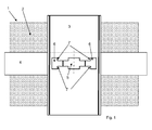
- the formwork is placed on a substantially horizontal surface (floor or floor slab) so that the stiffeners of the panels are arranged in the vertical direction.
- the ribs of the grid sheet perpendicularly cross the stiffeners and are therefore arranged horizontally and preferably at regular intervals over the entire height of the panel.
- the notions of vertical and horizontal are relative because the entire formwork can be rotated at an angle of 90 °. Thus the vertical elements at the beginning become horizontal and vice versa.
- a panel can be used as a single wall and placed either vertically against a wall to form a simple formwork, or horizontally for the realization of slabs.
- the form is formed by two panels arranged vertically and parallel to each other. They can be connected by a connecting device creating a space to be filled with a material such as concrete.
- a panel can be arranged vertically against a wall to form a simple formwork. It can also be used as a basis for the construction of various civil engineering works such as a slab of floor or roof, poles, beams, pillars etc.
- a panel can be arranged vertically against a wall to form a simple formwork. It can also be used as a base for the construction of a slab or roof, poles, beams, pillars and various civil engineering works can be built using the panel
- the ribs are profiled V-shaped or U-shaped solid metal parts integrated into the mesh of the sheet for stiffening stiffening manner.
- the grid sheet is preferably attached at each intersection of a rib with a stiffener to minimize deformations caused by the weight of concrete poured into the formwork using these panels.
- This fixing is performed by crimping in which at least one tongue of the metal of the rib is cut by stamping and bent in a corresponding hole of the stiffener.
- the recess forms a stop which prevents the exit of the tongue out of the orifice under the effect of pressure forces exerted by the concrete on the mesh. This stop bears against the stiffener on one side of the narrow part of the corresponding orifice.
- a preferred form of the tongue comprises two recesses forming two symmetrical abutments facing one another. These abutments bear against the stiffener on each side of the narrow portion of the orifice under the effect of pressure forces on the grid sheet.
- a formwork panel (1) comprises a mesh metal sheet (2) extending over a plurality of stiffeners (3) arranged parallel to one another at regular intervals preferably.
- the grid sheet (2) has a plurality of parallel ribs (4) crossing the stiffeners (3), perpendicular preferably, and also arranged at regular intervals on the surface of the sheet (2).
- the grid sheet (2) is preferably crimped at each intersection between the ribs (4) and the stiffeners (3) in order to minimize the deformations due to the pressure of the concrete and ensure optimum fixation.
- the stiffeners (3) consist of profiled steel bars generally U-shaped as shown in sectional views of figure 4 and 5 .
- the mesh sheet (2) is applied against the lower sides of the U-shaped sections and held by the ribs (4) at each crossing with these profiles.
- the ribs (4) are also U-shaped with the flat bottom portion placed on the stiffeners (3).
- the screen (2) is made by a known method, by stretching or deployment of a punched steel sheet with a plurality of blades.
- the ribs (4) are formed by stamping at predefined intervals of the sheet prior to deployment. They thus constitute integral parts of the screen sheet (2) without being reported on the screen as additional parts.
- the width of the U ribs (4) is 1.5 to 2.5 cm with a width of U stiffeners (3) of about 5 cm.
- the profile of the ribs (4) may have a different shape without a flat portion applied against the stiffener such as V-shaped where the edge is placed on the stiffener (3).
- the crimping operation locally deforms the rib (4) so as to flatten it in the vicinity of the tongues (6). This deformation is considered acceptable both in terms of the strength of the crimping and the surface of the panel where the concrete coating compensates for irregularities.
- the figure 1 shows an enlarged view of a preferred example of crimping according to the invention at the intersection of a rib (4) and a stiffener (3) seen from its inner face to the bottom of the U-shaped section.
- the perpendicularly crossing rib the stiffener is supported on the outer face of the U-shaped section.
- the stiffener (3) and the rib (4) comprise an orifice (5) traversed by tabs (6, 6 ') resulting from stamping performed at once. in the rib (4) and the stiffener.
- the tabs (6, 6 ') are bent, for example, on two opposite edges of the orifice (8) towards the inside of the U-shaped section as shown in FIG.
- the tabs (6) issuing from the rib (4) passing through the orifice (5).
- They each comprise a part of a given width (5.6 mm in one embodiment) whose end is attached to the rib (4), respectively to the stiffener (3) and a wider part (8 mm for example) having one end free.
- the contour of the junction of the narrow part and the wider part of a tongue (6, 6 ') forms two stops (7, 7') symmetrical preferably placed one facing the other. These stops (7, 7 ') have a contour preferably forming a right angle and are located at a predetermined distance from one end of the tongue (6, 6'), for example about 5 mm from the end free of the tongue (6, 6 '). Each abutment (7, 7 ') of width 1.2 mm in the example plays a role of locking the tongue (6) issuing from the rib (4) once bent over the edge (8) of the orifice (5).
- the width of the orifice (5) in the vicinity of the attached end of the tongue (6) is less than the width of said orifice (5) near its center. This difference in width constituting the abutments (7) makes it possible to prevent the tabs (6) issuing from the rib (4) from leaving the orifice (5) from being pressed against the mesh sheet (2).
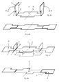
- the figure 2a shows a first crimping option in which the respective tabs (6, 6 ') issuing from the stiffener (3) and the rib (4) are bent substantially at right angles to the plane of the orifice (5).
- a crimp of this type has a clearance equivalent to the distance separating the attached end of the tongue (6) and the stops (7) (about 5 mm according to the example).
- Internal pressure P due to the filling concrete on the grid sheet (2) will advance the grid sheet (2) relative to the stiffeners (3) leaving a space equivalent to the clearance between the stiffeners (3) and the ribs (4) .
- This movement remains limited to the game thanks to the stops (7) of the tongues (6) which prevent the release of these out of their orifices (5) corresponding.
- play is reduced to a minimum.
- the tongues (6, 6 ') are folded against the internal face of the stiffener (3) at the bottom of the U-section using a suitable tool.
- the figure 2b shows a crimping in which the two tabs (6, 6 ') of the stiffener (3) and the rib (4) are folded symmetrically along their ends attached to the edge (8) of the orifice (5) so as to apply against the face of the stiffener (3) on two opposite sides of the orifice (5) (arrows R).
- This type of crimping provides better resistance of the mesh (2) on the stiffeners (3) leaving no clearance between the ribs (4) and the stiffeners (3) as presented in the first option.
- the Figure 2c shows the behavior of a crimped tab (6, 6 ') folded as shown in FIG. figure 2b when pressure forces P are exerted on the grid sheet (2).
- the pressure P causes the tongues (6) coming from the rib (4) to be straightened so as to form an angle close to 90 degrees with the plane of the orifice (5) or that of the internal face of the stiffener profile (3). ), the tabs (6 ') from the stiffener (3) remaining folded.
- the abutments (7) rest on the inner face of the stiffener (3) at the edge (8) of the narrow portion of the orifice (5) preventing the exit of the tongue (6).
- the stall removal problem (2) proper crimping tabs of constant width over their entire length as described in document W02007 / 079989 is thus solved by stops (7) acting as locking.
- figure 2d shows tabs each having a recess acting as a stop.
- the staggered arrangement of the recesses avoids a torsion effect of the rib at the crimping under the effect of pressure forces.
- the asymmetrical shape of the orifice (5) corresponds to the shape of each of the tongues.
- the preferred configuration of the crimping corresponds to that comprising symmetrical tongues with two recesses forming two abutments one facing each other as represented by the figures 1 , 2a, 2b and 2c .
- the advantage of the crimping is that it can be done quickly with a suitable machine tool allowing at first time to stamp the rib (4) and the stiffener (3) and in a second time fold respectively the tabs (6) of the rib (4) and the tongues (6 ') of the stiffener (3) in the orifice (5) of the stiffener (3).
- stamping and bending operations of the tongues (6, 6 ') are performed simultaneously when the ribs (4) and the stiffeners (3) are kept in their final position on the machine.
- the orifices (5) of the stiffeners (3) can be stamped during a preliminary stage. In this case, only the tabs (6) from the ribs are folded towards the inner face of the profile of the stiffener (3) during crimping.
- This variant requires a prior positioning of the stiffeners (3) and an alignment of the orifices (5) accurate with respect to the ribs (4) of the mesh (2) so as to stamp and fold the tongues (6) under optimal conditions.
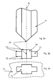
- the invention also relates to a crimping tool of a plurality of stiffeners (3) to a grid sheet (2) having a plurality of ribs (4) forming a panel (1) formwork comprising a stamp (9) and a support (14) capable of forming an orifice (5) and two tabs (6) at an intersection between a rib (4) and a stiffener (3) having a first portion with an end attached to the rib (4) and a free end characterized in that the end of the die (9) forms a symmetrical tip with a central edge (12) and two pairs of lateral edges (13) inclined perpendicular to the central edge (12) and in that the section comprises a central portion of greater width than the width of the parts located on either side of the central part, said stamp (9) and said support (14) being able to create two opposite symmetrical tongues (6) having in the vicinity the end attached to the rib (4), a first portion of width less than the width of a second portion in the vicinity of the free end, the contour of the two parts
- the stamping of tabs (6, 6 ') and the orifice (5) as illustrated by the Figures 2a to 2c is performed with tools comprising a stamp (9) and a support (14) as represented by the Figures 3a to 3c .
- the section of the stamp (9) has a shape corresponding to that of the orifice (5) with a part near the center wider than the parts located on either side of said center.
- the end forms a tip with a central sharp edge (12) for creating the free ends of each tongue (6, 6 ').
- the cutting of the rest of the contour of the tongues (6) with the stops (7) is performed by two pairs of sharp edges (13) sideways inclined perpendicularly to each side of the central edge (12).
- the figure 3b shows a top view of the tip of the stamp (9) with the central ridge (12) passing through the wide part of the section.
- the stamp (9) first passes through the metal of the rib (4) then that of the stiffener (3) while cutting in a single operation the tongues (6, 6 ') and the orifice (5) both in the rib (4) and in the stiffener (3).
- the support (14) illustrated by the figure 3c having a window (15) similar to the orifice (5) created by the stamp (9) is placed against the inner face of the stiffener (3) facing the stamp (9) so as to slide it after having formed the tabs (6, 6 ') in the metal of the rib (4) and the stiffener (4).
- the window (15) of the support (14) has a depth dimensioned so as to position the tabs (6, 6 ') perpendicular to the plane of the window (15).
- the tabs (6, 6 ') are then folded against the inner face of the stiffener profile (3) with a suitable tool after removal of the stamp (9) and the support (14). .
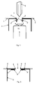
- the figure 4 shows a schematic form of a stamping tool (9) for making an orifice (5) both through the rib (4) and the stiffener (3) while forming tabs opposite to one another with respect to the other with each end attached to the edge (8) of the two opposite sides of the orifice (5) and a free end.
- the tongues (6, 6 ') directed towards the inner face of the stiffener profile (3) are folded against this face by means of a crimping tool (16) from the underside of the panel (1).
- a support portion of the not shown die acting after removal of the stamp presses the rib (4) on an area adjacent the orifice (5) to maintain the rib assembly (4) stiffener (3) when the folding tool (16) folds the tabs (6, 6 ').
- This tool (16) has a shaped end dimensioned and adapted to bend the tabs (6, 6 ') against the inner face of the stiffener (3) as illustrated by the figure 5 .
- the end of this tool (16) of folding can deviate as it advances to completely flatten the tabs (6, 6 ') against the stiffener (3).
- crimping according to the invention can be performed with a single tongue (6, 6 ') when for example the width of the U of the stiffener is insufficient to contain two tabs (6, 6') symmetrical opposite and folded down share and other of the orifice (5).
- the outline of the orifice (5) corresponds to the contour of a tongue (6) with two parts of different width as represented by the figures 1 , 2a, 2b and 2c considering only half left or right of the axis of symmetry A.
- the stamp (9) also adapted to form a tongue, has an asymmetrical tip whose shape corresponds to the left half or the half right with respect to the axis of symmetry A of the point represented by the Figures 3a and 3b .
- the window (15) of the support (14) naturally has a shape corresponding to one of the halves with respect to the axis A of the form illustrated by the figure 3c .
- the figure 6 illustrates an example of crimping with a single tongue (6, 6 ') per orifice (5).
- the stamping of the tongues (6, 6 ') is carried out so that they are retained alternately on the straight sides and left ports (5) aligned along the same rib (4).
- the tongues (6, 6 ') can also be alternately attached to the right and left sides of each orifice (5) along each stiffener (3). They thus have a staggered configuration on all the intersections between the ribs (4) and the stiffeners (3) of the panel (1)
- the manufacture of a panel (1) is performed by a machine on which the grid sheet (2) is held temporarily flat on stiffeners (3) by means of clamping devices.
- stamping and folding steps of the tongues (6, 6 ') are generally performed simultaneously on a plurality of intersections between at least one rib (4) and stiffeners (3) by a plurality of stamping tools. (9) and drawdown (16). These tools, aligned on at least one support parallel to the ribs (4) and arranged opposite said intersections advance along the interval between the ribs (4) in order to crimp the mesh sheet (2) at each crossing of the ribs (4) with the stiffeners (3).
- the present invention also relates to a formwork comprising two panels (1), as described above, placed facing each other and connected by connecting elements articulated to the panels by means of the stiffeners (3). .
- the wall erected with integrated formwork as described above is also an object of the present invention.
- the gap between the two panels (1) is filled with concrete or similar material.
- a concrete slab made with a panel (1) described above is also an object of the present invention.
- the slab is made by placing the panel (1) generally horizontally with the face having the stiffeners (3) directed upwards.
- Reinforcing reinforcements are generally placed on the stiffeners before pouring a layer of concrete preferably uniform on this face.
- the quantity of reinforcement and the thickness of the concrete layer are determined according to the slab range, the loads, the concrete quality, etc.
Landscapes
- Engineering & Computer Science (AREA)
- Architecture (AREA)
- Civil Engineering (AREA)
- Structural Engineering (AREA)
- Mechanical Engineering (AREA)
- Physics & Mathematics (AREA)
- Electromagnetism (AREA)
- Forms Removed On Construction Sites Or Auxiliary Members Thereof (AREA)
Abstract
Description
La présente invention concerne le domaine des coffrages destinés à la construction d'un mur ou d'une dalle en béton ou matériau semblable. Plus précisément, elle se rapporte aux parois coffrantes ou panneaux de coffrage qui constituent le coffrage proprement dit. Un panneau comprend une feuille grillagée s'étendant sur des barres verticales appelées raidisseurs espacés à intervalles prédéfinis fixés à la feuille grillagée.The present invention relates to the field of formwork for the construction of a wall or slab of concrete or similar material. More specifically, it refers to the formwork walls or shuttering panels that constitute the formwork itself. A panel comprises a screen sheet extending over vertical bars called stiffeners spaced at predefined intervals attached to the screen sheet.
Dans le cas d'un mur ou d'une paroi, le coffrage est formé par des panneaux disposés verticalement et parallèlement l'un en face de l'autre. Ils peuvent être reliés par un dispositif de liaison créant un espace destiné à être rempli d'un matériau tel que le béton.In the case of a wall or a wall, the formwork is formed by panels arranged vertically and parallel to each other opposite. They can be connected by a connecting device creating a space to be filled with a material such as concrete.
Un tel système de coffrage est utilisé en général en tant que coffrage perdu ou intégré c'est-à-dire qu'il subsiste comme faisant partie intégrante du mur après avoir coulé le béton dans l'espace séparant les deux panneaux.Such a formwork system is generally used as a formwork lost or integrated that is to say that it remains as an integral part of the wall after pouring the concrete in the space between the two panels.
Le document
Le coffrage avec ses deux parois coffrantes munies des raidisseurs et assemblées avec les dispositifs de liaison sont préfabriqués en usine. Il est transporté sur le chantier de construction sous forme pliée grâce aux articulations des éléments de liaisons sur les raidisseurs. L'avantage d'un tel coffrage est sa maniabilité et sa rapidité de montage sur le chantier avec un minimum d'outillage et de main d'oeuvre. Afin de minimiser les coûts globaux de construction et d'assurer une qualité élevée des murs érigés, chaque étape de la fabrication du coffrage doit être optimisée tant en rapidité d'exécution qu'en fiabilité des composants ou du produit fini. Un composant important est ici la paroi coffrante ou le panneau de coffrage conçu pour résister aux déformations dues à la pression et au poids du béton coulé dans le coffrage formé par ces panneaux.The formwork with its two formwork walls equipped with stiffeners and assembled with the connecting devices are prefabricated at the factory. It is transported to the construction site in folded form thanks to the joints of the elements of links on the stiffeners. The advantage of such a formwork is its maneuverability and speed of assembly on site with a minimum of tools and manpower. In order to minimize the overall construction costs and to ensure a high quality of the erected walls, each step of the formwork manufacture must be optimized both in speed of execution and reliability of the components or the finished product. An important component here is the formwork wall or the formwork panel designed to withstand the deformations due to the pressure and weight of concrete poured into the formwork formed by these panels.
Le document
Le document
Le document
Selon un exemple de réalisation pratique, l'orifice est étampé en forme de rectangle de manière à créer des languettes à la fois dans le métal de la nervure et dans celui du raidisseur attachées aux deux petits côtés opposés du rectangle. Les languettes dirigées vers la face interne du profilé du raidisseur sont ensuite rabattues contre cette face dans une zone adjacente aux petits côtés du rectangle.According to a practical embodiment, the orifice is stamped in the form of a rectangle so as to create tabs both in the metal of the rib and in that of the stiffener attached to the two small opposite sides of the rectangle. The tabs directed towards the inner face of the stiffener profile are then folded against this face in an area adjacent to the short sides of the rectangle.
Des essais avec des coffrages constitués de panneaux avec grillage serti selon la méthode ci-dessus ont montré que sous une pression élevée exercée par du béton coulé entre les deux panneaux, les languettes rabattues des nervures peuvent se redresser et traverser l'orifice du raidisseur. Ce relâchement du sertissage entraîne un détachement local de la feuille grillagée du raidisseur et provoque des renflements indésirables de la surface externe du coffrage rempli de béton. Le détachement de la feuille grillagée peut même se généraliser à toute la paroi coffrante s'il n'est pas détecté à temps lors du coulage du béton Ce phénomène est encore accentué lorsque la qualité, l'épaisseur et la dureté de l'acier utilisé pour la fabrication du grillage sont insuffisantes.Tests with formwork made of panels with grid crimped according to the above method have shown that under a high pressure exerted by poured concrete between the two panels, the folded tabs of the ribs can straighten and pass through the stiffener orifice. This loosening of the crimping results in a local detachment of the mesh sheet from the stiffener and causes undesirable bulges of the outer surface of the formwork filled with concrete. The detachment of the mesh sheet can even be generalized to the entire formwork wall if it is not detected in time during the pouring of the concrete. This phenomenon is further accentuated when the quality, the thickness and the hardness of the steel used. for the manufacture of the mesh are insufficient.
Lorsque les languettes sont repliées sur la face externe des parois comme dans l'agrafage des raidisseurs au grillage décrit dans le document
Une fixation avec des vis ou autres moyens d'attache ajoute des pièces supplémentaires au panneau, ce qui n'est pas souhaitable lorsque la fabrication doit être rationalisée et automatisée au maximum surtout pour des grandes séries.Fastening with screws or other fastening means adds additional parts to the panel, which is undesirable when the manufacturing has to be streamlined and automated to the maximum especially for large series.
Par rapport à la soudure par points, le sertissage du grillage aux raidisseurs présente des avantages non négligeables à savoir:
- le sertissage peut se réaliser avec un outillage automatisé, indépendamment des conditions extérieures et sans altération du traitement de surface de l'acier qui est en général galvanisé.
- les défauts éventuels de fixation par sertissage sont visibles immédiatement et peuvent être corrigés avant la sortie du coffrage de l'usine.
- le sertissage ne dégrade pas le traitement de surface de l'acier comme le ferait la soudure par oxydation des points de fixation de la feuille grillagée nuisant à la durée de vie du mur construit avec le coffrage intégré.
- le sertissage ne nécessite pas un environnement particulièrement propre et exempt de poussières impliquant des conditions de fabrication onéreuses à mettre en place et à respecter.
- crimping can be achieved with automated tooling, regardless of external conditions and without altering the surface treatment of steel which is usually galvanized.
- any crimping fixing defects are visible immediately and can be corrected before the factory shuttering is removed.
- crimping does not degrade the surface treatment of the steel as would the oxidation welding of the attachment points of the mesh sheet adversely affecting the life of the wall built with the integrated formwork.
- crimping does not require a particularly clean and dust-free environment involving expensive manufacturing conditions to implement and respect.
Le but de la présente invention est d'améliorer notablement la solidité du sertissage de l'art antérieur tout en conservant les avantages propres au sertissage par rapport à la fixation du grillage par soudure et autres moyens d'attache. De plus, le sertissage permet de réduire les coûts de production et de rationaliser la fabrication en grande série des panneaux de coffrage en usine tout en garantissant une résistance maximale aux murs construits avec ce type de coffrage.The object of the present invention is to significantly improve the strength of the crimping of the prior art while retaining the advantages of crimping with respect to the fixing of the mesh by welding and other fastening means. In addition, crimping reduces production costs and streamlines the mass production of factory formwork panels while ensuring maximum strength for walls built with this type of formwork.
Ce but est atteint par un panneau pour coffrage de murs ou de dalles en béton comprenant une feuille métallique grillagée renforcée d'une part par une pluralité de raidisseurs formés de barres métalliques rigides profilées disposées parallèlement les unes par rapport aux autres et espacées à intervalles prédéfinis, et d'autre part par des nervures intégrées au grillage de la feuille espacées à intervalles prédéfinis et croisant les raidisseurs, la feuille grillagée étant fixée sur les raidisseurs au moyen d'un sertissage effectué au niveau d'au moins une intersection entre une nervure et un raidisseur de sorte qu'au moins une portion de métal de la nervure, formant une languette ayant une extrémité attachée à la nervure et une extrémité libre, maintient le raidisseur en passant à travers un orifice dudit raidisseur, l'orifice ayant une forme correspondant à la forme de la languette, ledit panneau est caractérisé en ce que la languette comporte, au voisinage de l'extrémité attachée à la nervure, une première partie de largeur inférieure à la largeur d'une seconde partie au voisinage de l'extrémité libre, le contour des deux parties formant à leur jonction au moins un décrochement à une distance prédéterminée de l'une des extrémités de la languette, ledit décrochement formant une butée empêchant le dégagement de la languette hors de l'orifice correspondant sous l'effet de forces de pression exercées sur la feuille métallique grillagée.This object is achieved by a panel for formwork of walls or concrete slabs comprising a mesh metal sheet reinforced on the one hand by a plurality of stiffeners formed of profiled rigid metal bars arranged parallel to each other and spaced at predetermined intervals and on the other hand ribs integrated in the mesh of the sheet spaced at predetermined intervals and crossing the stiffeners, the mesh sheet being fixed on the stiffeners by means of a crimping performed at at least one intersection between a rib and a stiffener so that at least one metal portion of the rib, forming a tongue having one end attached to the rib and a free end, holds the stiffener through an orifice of said stiffener, the orifice having a shape corresponding to the shape of the tongue, said panel is characterized in that the tongue comprises, at sinage of the end attached to the rib, a first portion of width less than the width of a second portion in the vicinity of the free end, the contour of the two parts forming at their junction at least one recess at a predetermined distance from one end of the tongue, said recess forming a stop preventing the release of the tongue out of the corresponding hole under the effect of pressure forces exerted on the wire mesh sheet.
Dans la pratique, lors de la construction d'un mur, le coffrage est posé sur une surface sensiblement horizontale (sol ou dalle de plancher) de manière à ce que les raidisseurs des panneaux soient disposés dans le sens vertical. Les nervures de la feuille grillagée croisent perpendiculairement les raidisseurs et sont donc disposées horizontalement et de préférence à intervalles réguliers sur toute la hauteur du panneau. Les notions de vertical et d'horizontal sont relatives car l'ensemble du coffrage peut être tourné selon un angle de 90°. Ainsi les éléments verticaux à l'origine deviennent horizontaux et vice versa.In practice, during the construction of a wall, the formwork is placed on a substantially horizontal surface (floor or floor slab) so that the stiffeners of the panels are arranged in the vertical direction. The ribs of the grid sheet perpendicularly cross the stiffeners and are therefore arranged horizontally and preferably at regular intervals over the entire height of the panel. The notions of vertical and horizontal are relative because the entire formwork can be rotated at an angle of 90 °. Thus the vertical elements at the beginning become horizontal and vice versa.
Un panneau peut être utilisé comme paroi simple et placée soit verticalement contre un mur pour constituer un coffrage simple, soit horizontalement pour la réalisation de dalles.A panel can be used as a single wall and placed either vertically against a wall to form a simple formwork, or horizontally for the realization of slabs.
Dans le cas d'un mur ou d'une paroi, le coffrage est formé par deux panneaux disposés verticalement et parallèlement l'un en face de l'autre. Ils peuvent être reliés par un dispositif de liaison créant un espace destiné à être rempli d'un matériau tel que le béton. Un panneau peut être disposé verticalement contre un mur pour constituer un coffrage simple. Il peut également servir de base pour la construction de divers ouvrages de génie civil tels qu'une dalle de plancher ou de toiture, des poteaux, des poutres, des piliers etc.In the case of a wall or wall, the form is formed by two panels arranged vertically and parallel to each other. They can be connected by a connecting device creating a space to be filled with a material such as concrete. A panel can be arranged vertically against a wall to form a simple formwork. It can also be used as a basis for the construction of various civil engineering works such as a slab of floor or roof, poles, beams, pillars etc.
Un panneau peut être disposé verticalement contre un mur pour constituer un coffrage simple. Il peut également servir de base pour la construction d'une dalle ou d'une toiture, des poteaux, des poutres, des piliers et divers ouvrages de génie civil peuvent être construits à l'aide du panneauA panel can be arranged vertically against a wall to form a simple formwork. It can also be used as a base for the construction of a slab or roof, poles, beams, pillars and various civil engineering works can be built using the panel
Les nervures sont des parties profilées en V ou en U longilignes en métal plein intégrées au grillage de la feuille servant à le rigidifier à la façon de raidisseurs.The ribs are profiled V-shaped or U-shaped solid metal parts integrated into the mesh of the sheet for stiffening stiffening manner.
La feuille grillagée est fixée de préférence à chaque intersection d'une nervure avec un raidisseur afin de minimiser les déformations causées par le poids du béton coulé dans le coffrage utilisant ces panneaux. Cette fixation est effectuée par sertissage dans lequel au moins une languette du métal de la nervure est découpée par étampage puis recourbée dans un orifice correspondant du raidisseur.The grid sheet is preferably attached at each intersection of a rib with a stiffener to minimize deformations caused by the weight of concrete poured into the formwork using these panels. This fixing is performed by crimping in which at least one tongue of the metal of the rib is cut by stamping and bent in a corresponding hole of the stiffener.
A l'endroit où la largeur de la languette change, le décrochement forme une butée qui empêche la sortie de la languette hors de l'orifice sous l'effet de forces de pression exercées par le béton sur le grillage. Cette butée s'appuie contre le raidisseur sur un côté de la partie étroite de l'orifice correspondant.At the point where the width of the tongue changes, the recess forms a stop which prevents the exit of the tongue out of the orifice under the effect of pressure forces exerted by the concrete on the mesh. This stop bears against the stiffener on one side of the narrow part of the corresponding orifice.
Une forme préférée de la languette comporte deux décrochements formant deux butées symétriques situées l'une en regard de l'autre. Ces butées s'appuient contre le raidisseur de chaque côté de la partie étroite de l'orifice sous l'effet de forces de pression sur la feuille grillagée.A preferred form of the tongue comprises two recesses forming two symmetrical abutments facing one another. These abutments bear against the stiffener on each side of the narrow portion of the orifice under the effect of pressure forces on the grid sheet.
L'invention sera mieux comprise grâce à la description détaillée qui va suivre et qui se réfère aux dessins annexés qui sont donnés à titre d'exemples nullement limitatifs, à savoir:
- la
figure 1 représente un sertissage selon l'invention à une intersection entre un raidisseur et une nervure de la feuille grillagée. - la
figure 2a montre une vue schématique des languettes du sertissage redressées de chaque côté de l'orifice. - la
figure 2b montre les languettes de lafigure 2a rabattues de chaque côté de l'orifice. - la
figure 2c illustre la position des languettes et l'effet des butées lorsqu'une pression est exercée sur la feuille grillagée. - la
figure 2d illustre un exemple de languettes opposées rabattues comportant chacune un décrochement disposé en quinconce l'un par rapport à l'autre. - la
figure 3a représente une vue frontale de l'extrémité d'une étampe servant à découper les languettes et former l'orifice que les languettes traversent pour réaliser le sertissage. - la
figure 3b montre une vue de dessus de l'extrémité de l'étampe de lafigure 3a - la
figure 3c montre un orifice tel qu'il serait usiné dans un support fixe avec un contour correspondant à celui d'une section de l'étampe. - la
figure 4 illustre schématiquement sur une vue en coupe d'un raidisseur l'étape de rabattement des languettes étampées contre la face interne d'un raidisseur. - la
figure 5 illustre schématiquement le résultat obtenu après rabattement des languettes contre la face interne du raidisseur. - la
figure 6 illustre schématiquement une variante du sertissage dans laquelle l'orifice comporte des languettes sur un seul côté. Elles sont retenues alternativement sur chaque côté des orifices étampés le long d'une nervure.
- the
figure 1 represents a crimp according to the invention at an intersection between a stiffener and a rib of the grid sheet. - the
figure 2a shows a schematic view of the tongues crimping rectified on each side of the orifice. - the
figure 2b shows the tabs of thefigure 2a folded on each side of the hole. - the
Figure 2c illustrates the position of the tongues and the effect of the stops when pressure is exerted on the grid sheet. - the
figure 2d illustrates an example of opposite tabs folded each having a recess arranged staggered with respect to each other. - the
figure 3a is a front view of the end of a stamp for cutting the tabs and form the hole that the tabs through to achieve the crimping. - the
figure 3b shows a top view of the end of the stamp of thefigure 3a - the
figure 3c shows an orifice as it would be machined in a fixed support with a contour corresponding to that of a section of the stamp. - the
figure 4 illustrates schematically in a sectional view of a stiffener the step of folding the tabs stamped against the inner face of a stiffener. - the
figure 5 schematically illustrates the result obtained after folding of the tabs against the inner face of the stiffener. - the
figure 6 schematically illustrates a variant of crimping in which the orifice has tabs on one side. They are held alternately on each side of the orifices stamped along a rib.
Un panneau de coffrage (1) comprend une feuille métallique grillagée (2) s'étendant sur une pluralité de raidisseurs (3) disposés parallèlement les uns par rapport aux autres à intervalles réguliers de préférence. La feuille grillagée (2) comporte une pluralité de nervures (4) parallèles croisant les raidisseurs (3), perpendiculairement de préférence, et également disposées à intervalles réguliers sur la surface de la feuille (2). La feuille grillagée (2) est sertie de préférence à chaque intersection entre les nervures (4) et les raidisseurs (3) afin de réduire au minimum les déformations dues à la pression du béton et assurer une fixation optimale.A formwork panel (1) comprises a mesh metal sheet (2) extending over a plurality of stiffeners (3) arranged parallel to one another at regular intervals preferably. The grid sheet (2) has a plurality of parallel ribs (4) crossing the stiffeners (3), perpendicular preferably, and also arranged at regular intervals on the surface of the sheet (2). The grid sheet (2) is preferably crimped at each intersection between the ribs (4) and the stiffeners (3) in order to minimize the deformations due to the pressure of the concrete and ensure optimum fixation.
Les raidisseurs (3) sont constitués de barres d'acier profilées généralement en forme de U comme le montre les vues en coupe des
Le grillage (2) est réalisé selon un procédé connu, par étirement ou déploiement d'une feuille d'acier poinçonnée à l'aide d'une pluralité de lames. Les nervures (4) sont formées par emboutissage à intervalles prédéfinis de la feuille préalablement au déploiement. Elles constituent ainsi des parties intégrantes de la feuille grillagée (2) sans être rapportées sur le grillage comme pièces supplémentaires. Selon une réalisation pratique la largeur du U des nervures (4) est de 1.5 à 2.5 cm avec une largeur du U des raidisseurs (3) d'environ 5 cm.The screen (2) is made by a known method, by stretching or deployment of a punched steel sheet with a plurality of blades. The ribs (4) are formed by stamping at predefined intervals of the sheet prior to deployment. They thus constitute integral parts of the screen sheet (2) without being reported on the screen as additional parts. In a practical embodiment the width of the U ribs (4) is 1.5 to 2.5 cm with a width of U stiffeners (3) of about 5 cm.
Le profil des nervures (4) peut présenter une forme différente sans partie plane appliquée contre le raidisseur comme par exemple en forme de V où l'arête est posée sur le raidisseur (3). Dans ce cas, l'opération de sertissage déforme localement la nervure (4) de manière à l'aplatir dans le voisinage des languettes (6). Cette déformation est jugée acceptable tant au niveau de la solidité du sertissage qu'à celui de la surface du panneau où le revêtement de béton compense les irrégularités.The profile of the ribs (4) may have a different shape without a flat portion applied against the stiffener such as V-shaped where the edge is placed on the stiffener (3). In this case, the crimping operation locally deforms the rib (4) so as to flatten it in the vicinity of the tongues (6). This deformation is considered acceptable both in terms of the strength of the crimping and the surface of the panel where the concrete coating compensates for irregularities.
La
Le contour de la jonction de la partie étroite et de la partie plus large d'une languette (6, 6') forme deux butées (7, 7') symétriques de préférence placées l'une en regard de l'autre. Ces butées (7, 7') ont un contour formant de préférence un angle droit et sont situées à une distance prédéterminée de l'une les extrémités de la languette (6, 6'), par exemple à environ 5 mm de l'extrémité libre de la languette (6, 6'). Chaque butée (7, 7') de largeur 1.2 mm dans l'exemple joue un rôle de verrouillage de la languette (6) issue de la nervure (4) une fois recourbée sur le bord (8) de l'orifice (5). En effet, la largeur de l'orifice (5) au voisinage de l'extrémité attachée de la languette (6) est inférieure à la largeur dudit orifice (5) au voisinage de son centre. Cette différence de largeur constituant les butées (7) permet d'empêcher la sortie des languettes (6) issues de la nervure (4) hors de l'orifice (5) par pression sur la feuille grillagée (2).The contour of the junction of the narrow part and the wider part of a tongue (6, 6 ') forms two stops (7, 7') symmetrical preferably placed one facing the other. These stops (7, 7 ') have a contour preferably forming a right angle and are located at a predetermined distance from one end of the tongue (6, 6'), for example about 5 mm from the end free of the tongue (6, 6 '). Each abutment (7, 7 ') of width 1.2 mm in the example plays a role of locking the tongue (6) issuing from the rib (4) once bent over the edge (8) of the orifice (5). Indeed, the width of the orifice (5) in the vicinity of the attached end of the tongue (6) is less than the width of said orifice (5) near its center. This difference in width constituting the abutments (7) makes it possible to prevent the tabs (6) issuing from the rib (4) from leaving the orifice (5) from being pressed against the mesh sheet (2).
Il est à noter que d'autres formes d'orifice et de languettes correspondantes dont le contour comporte un ou des décrochements formant une ou des butées disposées de manière symétrique ou non sont également possibles pourvu que leur rôle de verrouillage soit maintenu.It should be noted that other forms of orifice and corresponding tabs whose contour comprises one or more recesses forming one or more abutments arranged symmetrically or not are also possible provided that their role of locking is maintained.
La
Selon une seconde option les languettes (6, 6') sont rabattues contre la face interne du raidisseur (3) au fond du profilé en U à l'aide d'un outil adéquat. La
La
L'exemple de la
L'avantage du sertissage est qu'il peut être effectué rapidement avec une machine outil appropriée permettant dans un premier temps d'étamper la nervure (4) et le raidisseur (3) et dans un deuxième temps replier respectivement les languettes (6) de la nervure (4) et les languettes (6') du raidisseur (3) dans l'orifice (5) du raidisseur (3). Afin de conserver un alignement précis des languettes (6) avec les orifices (5) correspondants, les opérations d'étampage et de courbure des languettes (6, 6') sont effectuées simultanément lorsque les nervures (4) et les raidisseurs (3) sont maintenus dans leur position définitive sur la machine.The advantage of the crimping is that it can be done quickly with a suitable machine tool allowing at first time to stamp the rib (4) and the stiffener (3) and in a second time fold respectively the tabs (6) of the rib (4) and the tongues (6 ') of the stiffener (3) in the orifice (5) of the stiffener (3). In order to maintain a precise alignment of the tongues (6) with the corresponding holes (5), stamping and bending operations of the tongues (6, 6 ') are performed simultaneously when the ribs (4) and the stiffeners (3) are kept in their final position on the machine.
Selon une variante les orifices (5) des raidisseurs (3) peuvent être étampés lors d'une étape préliminaire. Dans ce cas, seules les languettes (6) issues des nervures sont repliées vers la face interne du profil du raidisseur (3) lors du sertissage. Cette variante nécessite un positionnement préalable des raidisseurs (3) et un alignement des orifices (5) précis par rapport aux nervures (4) du grillage (2) de manière à étamper et rabattre les languettes (6) dans des conditions optimales.According to one variant, the orifices (5) of the stiffeners (3) can be stamped during a preliminary stage. In this case, only the tabs (6) from the ribs are folded towards the inner face of the profile of the stiffener (3) during crimping. This variant requires a prior positioning of the stiffeners (3) and an alignment of the orifices (5) accurate with respect to the ribs (4) of the mesh (2) so as to stamp and fold the tongues (6) under optimal conditions.
L'invention concerne également un outillage de sertissage d'une pluralité de raidisseurs (3) à une feuille grillagée (2) comportant une pluralité de nervures (4) formant un panneau (1) de coffrage comprenant une étampe (9) et un support (14) aptes à former un orifice (5) et deux languettes (6) à une intersection entre une nervure (4) et un raidisseur (3) ayant une première partie avec une extrémité attachée à la nervure (4) et une extrémité libre caractérisé en ce que l'extrémité de l'étampe (9) forme une pointe symétrique avec une arête centrale (12) et deux paires d'arêtes latérales (13) inclinées perpendiculaires à l'arête centrale (12) et en ce que la section comporte une partie centrale de largeur supérieure à la largeur des parties situées de part et d'autre de la partie centrale, ladite étampe (9) et ledit support (14) étant aptes à créer deux languettes (6) symétriques opposées comportant au voisinage de l'extrémité attachée à la nervure (4), une première partie de largeur inférieure à la largeur d'une seconde partie au voisinage de l'extrémité libre, le contour des deux parties formant à leur jonction deux butées (7) situées l'une en regard de l'autre à une distance prédéterminée de l'une des extrémités de la languette (6).The invention also relates to a crimping tool of a plurality of stiffeners (3) to a grid sheet (2) having a plurality of ribs (4) forming a panel (1) formwork comprising a stamp (9) and a support (14) capable of forming an orifice (5) and two tabs (6) at an intersection between a rib (4) and a stiffener (3) having a first portion with an end attached to the rib (4) and a free end characterized in that the end of the die (9) forms a symmetrical tip with a central edge (12) and two pairs of lateral edges (13) inclined perpendicular to the central edge (12) and in that the section comprises a central portion of greater width than the width of the parts located on either side of the central part, said stamp (9) and said support (14) being able to create two opposite symmetrical tongues (6) having in the vicinity the end attached to the rib (4), a first portion of width less than the width of a second portion in the vicinity of the free end, the contour of the two parts forming at their junction two abutments (7) located one opposite the other at a predetermined distance from one end of the tongue (6).
L'étampage de languettes (6, 6') et de l'orifice (5) comme illustrés par les
La
Le support (14) illustré par la
La
Lors d'une seconde étape facultative, les languettes (6, 6') dirigées vers la face interne du profilé du raidisseur (3) sont repliées contre cette face à l'aide d'un outil de rabattement (16) depuis la face inférieure du panneau (1). Une partie support de l'étampe non représentée intervenant après retrait de l'étampe appuie sur la nervure (4) sur une zone avoisinant l'orifice (5) afin de maintenir l'assemblage nervure (4) raidisseur (3) lorsque l'outil de rabattement (16) replie les languettes (6, 6'). Cet outil (16) comporte une extrémité de forme dimensionnée et adaptée de manière à recourber les languettes (6, 6') contre la face interne du raidisseur (3) comme illustré par la
Selon une variante, l'extrémité de cet outil (16) de rabattement peut s'écarter lors de son avancement afin d'aplatir complètement les languettes (6, 6') contre le raidisseur (3).According to a variant, the end of this tool (16) of folding can deviate as it advances to completely flatten the tabs (6, 6 ') against the stiffener (3).
Il est à noter que le sertissage selon l'invention peut être effectué avec une seule languette (6, 6') lorsque par exemple la largeur du U du raidisseur est insuffisante pour contenir deux languettes (6, 6') symétriques opposées et rabattues de part et d'autre de l'orifice (5). Dans ce cas, le contour de l'orifice (5) correspond au contour d'une languette (6) avec deux parties de largeur différente comme représenté par les
La
La fabrication d'un panneau (1) est effectuée par une machine sur laquelle la feuille grillagée (2) est maintenue temporairement à plat sur des raidisseurs (3) au moyen de dispositifs de serrage.The manufacture of a panel (1) is performed by a machine on which the grid sheet (2) is held temporarily flat on stiffeners (3) by means of clamping devices.
Les étapes d'étampage et de rabattement des languettes (6, 6') sont exécutées en général simultanément sur une pluralité d'intersections entre au moins une nervure (4) et des raidisseurs (3) par une pluralité d'outils d'étampage (9) et de rabattement (16). Ces outils, alignés sur au moins un support parallèle aux nervures (4) et disposés en regard des dites intersections avancent selon l'intervalle entre les nervures (4) afin de sertir la feuille grillagée (2) à chaque croisement des nervures (4) avec les raidisseurs (3).The stamping and folding steps of the tongues (6, 6 ') are generally performed simultaneously on a plurality of intersections between at least one rib (4) and stiffeners (3) by a plurality of stamping tools. (9) and drawdown (16). These tools, aligned on at least one support parallel to the ribs (4) and arranged opposite said intersections advance along the interval between the ribs (4) in order to crimp the mesh sheet (2) at each crossing of the ribs (4) with the stiffeners (3).
La présente invention concerne également un coffrage comprenant deux panneaux (1), tels que décrits ci-dessus, placés l'un en face de l'autre et connectés par des éléments de liaison articulés aux panneaux par l'intermédiaire des raidisseurs (3).The present invention also relates to a formwork comprising two panels (1), as described above, placed facing each other and connected by connecting elements articulated to the panels by means of the stiffeners (3). .
Ces éléments de liaison permettant de maintenir les panneaux (1), soit à un écartement définissant un intervalle destiné à recevoir du béton ou matériau similaire, soit replié pour le stockage et le transport.These connecting elements to maintain the panels (1), either at a gap defining a gap for receiving concrete or similar material, or folded for storage and transport.
Le mur érigé avec un coffrage intégré comme décrit ci-dessus constitue aussi un objet de la présente invention. L'intervalle entre les deux panneaux (1) est rempli de béton ou matériau similaire.The wall erected with integrated formwork as described above is also an object of the present invention. The gap between the two panels (1) is filled with concrete or similar material.
Une dalle en béton réalisée avec un panneau (1) décrit ci-dessus est également un objet de la présente invention. La dalle est réalisée en plaçant le panneau (1) généralement horizontalement avec la face comportant les raidisseurs (3) dirigée vers le haut. Des armatures de renforcement sont généralement posées sur les raidisseurs avant de couler une couche de béton de préférence uniforme sur cette face. La quantité des armatures et l'épaisseur de la couche de béton sont déterminées en fonction de la portée de la dalle, des charges, de la qualité du béton, etc.A concrete slab made with a panel (1) described above is also an object of the present invention. The slab is made by placing the panel (1) generally horizontally with the face having the stiffeners (3) directed upwards. Reinforcing reinforcements are generally placed on the stiffeners before pouring a layer of concrete preferably uniform on this face. The quantity of reinforcement and the thickness of the concrete layer are determined according to the slab range, the loads, the concrete quality, etc.
Claims (15)
Priority Applications (5)
| Application Number | Priority Date | Filing Date | Title |
|---|---|---|---|
| EP09150171A EP2206847A1 (en) | 2009-01-07 | 2009-01-07 | Formworking panel with secured setting |
| EP10700021A EP2386006A1 (en) | 2009-01-07 | 2010-01-06 | Panel for formwork with secured crimping |
| RU2011130251/03A RU2011130251A (en) | 2009-01-07 | 2010-01-06 | BENDING FORMWORK PANEL |
| PCT/EP2010/050084 WO2010079186A1 (en) | 2009-01-07 | 2010-01-06 | Panel for formwork with secured crimping |
| CN2010800040742A CN102272392A (en) | 2009-01-07 | 2010-01-06 | Panel for formwork with secured crimping |
Applications Claiming Priority (1)
| Application Number | Priority Date | Filing Date | Title |
|---|---|---|---|
| EP09150171A EP2206847A1 (en) | 2009-01-07 | 2009-01-07 | Formworking panel with secured setting |
Publications (1)
| Publication Number | Publication Date |
|---|---|
| EP2206847A1 true EP2206847A1 (en) | 2010-07-14 |
Family
ID=40637923
Family Applications (2)
| Application Number | Title | Priority Date | Filing Date |
|---|---|---|---|
| EP09150171A Withdrawn EP2206847A1 (en) | 2009-01-07 | 2009-01-07 | Formworking panel with secured setting |
| EP10700021A Withdrawn EP2386006A1 (en) | 2009-01-07 | 2010-01-06 | Panel for formwork with secured crimping |
Family Applications After (1)
| Application Number | Title | Priority Date | Filing Date |
|---|---|---|---|
| EP10700021A Withdrawn EP2386006A1 (en) | 2009-01-07 | 2010-01-06 | Panel for formwork with secured crimping |
Country Status (4)
| Country | Link |
|---|---|
| EP (2) | EP2206847A1 (en) |
| CN (1) | CN102272392A (en) |
| RU (1) | RU2011130251A (en) |
| WO (1) | WO2010079186A1 (en) |
Families Citing this family (1)
| Publication number | Priority date | Publication date | Assignee | Title |
|---|---|---|---|---|
| CN111366530B (en) * | 2020-03-26 | 2023-10-27 | 马鞍山十七冶工程科技有限责任公司 | Bonding plate fixing device for field bonding drawing detection test |
Citations (5)
| Publication number | Priority date | Publication date | Assignee | Title |
|---|---|---|---|---|
| FR2497857A1 (en) | 1981-01-13 | 1982-07-16 | Atlas Maisons | Metal profiles for prefabricated panel frames - have punched tongues to loop into and hold sheet metal panels |
| FR2712016A1 (en) | 1993-11-02 | 1995-05-12 | Coffratherm Ste Civile Invente | Method of manufacturing formwork walls for building and related production line. |
| WO2005042864A1 (en) | 2003-11-03 | 2005-05-12 | Polyfinance Coffor Holding S.A. | High-strength concrete wall formwork |
| WO2007079989A1 (en) | 2006-01-12 | 2007-07-19 | Polyfinance Coffor Holding S.A. | Formwork panel |
| WO2008041024A1 (en) * | 2006-10-04 | 2008-04-10 | Expamet Building Products Limited | Formwork system |
Family Cites Families (1)
| Publication number | Priority date | Publication date | Assignee | Title |
|---|---|---|---|---|
| CN2658251Y (en) * | 2003-11-03 | 2004-11-24 | 杨爱华 | Building form net without removing |
-
2009
- 2009-01-07 EP EP09150171A patent/EP2206847A1/en not_active Withdrawn
-
2010
- 2010-01-06 RU RU2011130251/03A patent/RU2011130251A/en not_active Application Discontinuation
- 2010-01-06 WO PCT/EP2010/050084 patent/WO2010079186A1/en active Application Filing
- 2010-01-06 EP EP10700021A patent/EP2386006A1/en not_active Withdrawn
- 2010-01-06 CN CN2010800040742A patent/CN102272392A/en active Pending
Patent Citations (5)
| Publication number | Priority date | Publication date | Assignee | Title |
|---|---|---|---|---|
| FR2497857A1 (en) | 1981-01-13 | 1982-07-16 | Atlas Maisons | Metal profiles for prefabricated panel frames - have punched tongues to loop into and hold sheet metal panels |
| FR2712016A1 (en) | 1993-11-02 | 1995-05-12 | Coffratherm Ste Civile Invente | Method of manufacturing formwork walls for building and related production line. |
| WO2005042864A1 (en) | 2003-11-03 | 2005-05-12 | Polyfinance Coffor Holding S.A. | High-strength concrete wall formwork |
| WO2007079989A1 (en) | 2006-01-12 | 2007-07-19 | Polyfinance Coffor Holding S.A. | Formwork panel |
| WO2008041024A1 (en) * | 2006-10-04 | 2008-04-10 | Expamet Building Products Limited | Formwork system |
Also Published As
| Publication number | Publication date |
|---|---|
| RU2011130251A (en) | 2013-02-20 |
| WO2010079186A1 (en) | 2010-07-15 |
| EP2386006A1 (en) | 2011-11-16 |
| CN102272392A (en) | 2011-12-07 |
Similar Documents
| Publication | Publication Date | Title |
|---|---|---|
| EP1756367B1 (en) | Lightweight metal joint for concrete surfaces | |
| EP1644592B1 (en) | High-strength concrete wall formwork | |
| FR2481248A1 (en) | LIGHTWEIGHT AND RESISTANT ARROW ELEMENTS FOR TELESCOPIC CRANE ARROW AND CRANE ARROW SHAPED OF SUCH ELEMENTS | |
| EP2674538B1 (en) | Modular construction and corresponding assembly method | |
| FR2991359A1 (en) | FORMWORK BANK OF A CONCRETE WALL | |
| WO2007079989A1 (en) | Formwork panel | |
| EP3483339B1 (en) | Method for easier renovation of expansion joint for concrete slabs shuttering system | |
| EP2206847A1 (en) | Formworking panel with secured setting | |
| CA2252007A1 (en) | Wall or casing made of metal sheets stretched over a frame or structure, and construction procedure | |
| EP1749951B1 (en) | Permanent formwork element and module for building such an element | |
| EP0568441A1 (en) | Load-bearing structure such as a floor, comprising beams and a concret slab and construction method therefor | |
| BE1017376A5 (en) | METAL JOINT FOR EXPANSION BETWEEN CONCRETE SLABS. | |
| FR2893058A1 (en) | Rubble wall, slab and concrete floor casing and mounting device, has profiled monoblock armature with upper part and upper wing presenting vertical bend edged with respect to upper wing, where upper part constitutes support for floor | |
| EP3428109A1 (en) | Dynamic and adaptive anchor for hoisting a construction element, especially thin elements, multi-configurations and multiple forces | |
| WO2018002276A1 (en) | Formwork panel | |
| FR3036419A1 (en) | REINFORCING BEAM FOR WALL FORMWORK OF SWIMMING WALL | |
| EP1176086A1 (en) | Frame with a reduced number of welds, bearer for such a chassis, and process for making such a bearer | |
| EP2722458B1 (en) | Roof gutter | |
| EP3221207B1 (en) | Assembly of reinforcement inserts made from a polymer material, with separable reinforcement inserts | |
| EP2505731B1 (en) | Method for manufacturing a sheet with open ribs intended for forming a framework for a composite floor | |
| EP1678389B1 (en) | Large-span self-supporting metal formwork | |
| FR2878877A1 (en) | Formwork block for e.g. manufacturing lintel, has vertical walls with flanges exceeding horizontal wall to form U-shape of height greater than beam, where inner sides of flanges have abutments separated at distance equal to beam`s thickness | |
| FR2969939A3 (en) | Cutting tool for severing metallic U-shaped cross-sectional profiles utilized as e.g. building elements, has support comprising recess that is opened towards top to transversally receive profile with respect to cutting plane | |
| FR3058168A1 (en) | PREMUR COMPRISING A STEEL FRAME AND BACK FRAME | |
| FR2962066A1 (en) | Method for manufacturing structural prefabricated concrete element i.e. beam, in bay cover, involves pouring concrete in longitudinal casing that is made of ultra high performance fiber concrete and fixed at reinforcement |
Legal Events
| Date | Code | Title | Description |
|---|---|---|---|
| PUAI | Public reference made under article 153(3) epc to a published international application that has entered the european phase |
Free format text: ORIGINAL CODE: 0009012 |
|
| AK | Designated contracting states |
Kind code of ref document: A1 Designated state(s): AT BE BG CH CY CZ DE DK EE ES FI FR GB GR HR HU IE IS IT LI LT LU LV MC MK MT NL NO PL PT RO SE SI SK TR |
|
| AX | Request for extension of the european patent |
Extension state: AL BA RS |
|
| AKY | No designation fees paid | ||
| REG | Reference to a national code |
Ref country code: DE Ref legal event code: R108 Effective date: 20110222 Ref country code: DE Ref legal event code: 8566 |
|
| STAA | Information on the status of an ep patent application or granted ep patent |
Free format text: STATUS: THE APPLICATION IS DEEMED TO BE WITHDRAWN |
|
| 18D | Application deemed to be withdrawn |
Effective date: 20110115 |