EP2206832A2 - Drainage device - Google Patents
Drainage device Download PDFInfo
- Publication number
- EP2206832A2 EP2206832A2 EP10000132A EP10000132A EP2206832A2 EP 2206832 A2 EP2206832 A2 EP 2206832A2 EP 10000132 A EP10000132 A EP 10000132A EP 10000132 A EP10000132 A EP 10000132A EP 2206832 A2 EP2206832 A2 EP 2206832A2
- Authority
- EP
- European Patent Office
- Prior art keywords
- cover
- dewatering device
- lighting
- drainage
- plastic body
- Prior art date
- Legal status (The legal status is an assumption and is not a legal conclusion. Google has not performed a legal analysis and makes no representation as to the accuracy of the status listed.)
- Withdrawn
Links
Images
Classifications
-
- E—FIXED CONSTRUCTIONS
- E01—CONSTRUCTION OF ROADS, RAILWAYS, OR BRIDGES
- E01C—CONSTRUCTION OF, OR SURFACES FOR, ROADS, SPORTS GROUNDS, OR THE LIKE; MACHINES OR AUXILIARY TOOLS FOR CONSTRUCTION OR REPAIR
- E01C11/00—Details of pavings
- E01C11/22—Gutters; Kerbs ; Surface drainage of streets, roads or like traffic areas
- E01C11/224—Surface drainage of streets
- E01C11/227—Gutters; Channels ; Roof drainage discharge ducts set in sidewalks
-
- E—FIXED CONSTRUCTIONS
- E01—CONSTRUCTION OF ROADS, RAILWAYS, OR BRIDGES
- E01C—CONSTRUCTION OF, OR SURFACES FOR, ROADS, SPORTS GROUNDS, OR THE LIKE; MACHINES OR AUXILIARY TOOLS FOR CONSTRUCTION OR REPAIR
- E01C17/00—Pavement lights, i.e. translucent constructions forming part of the surface
-
- E—FIXED CONSTRUCTIONS
- E03—WATER SUPPLY; SEWERAGE
- E03F—SEWERS; CESSPOOLS
- E03F5/00—Sewerage structures
- E03F5/04—Gullies inlets, road sinks, floor drains with or without odour seals or sediment traps
- E03F5/06—Gully gratings
-
- F—MECHANICAL ENGINEERING; LIGHTING; HEATING; WEAPONS; BLASTING
- F21—LIGHTING
- F21V—FUNCTIONAL FEATURES OR DETAILS OF LIGHTING DEVICES OR SYSTEMS THEREOF; STRUCTURAL COMBINATIONS OF LIGHTING DEVICES WITH OTHER ARTICLES, NOT OTHERWISE PROVIDED FOR
- F21V15/00—Protecting lighting devices from damage
- F21V15/01—Housings, e.g. material or assembling of housing parts
-
- F—MECHANICAL ENGINEERING; LIGHTING; HEATING; WEAPONS; BLASTING
- F21—LIGHTING
- F21V—FUNCTIONAL FEATURES OR DETAILS OF LIGHTING DEVICES OR SYSTEMS THEREOF; STRUCTURAL COMBINATIONS OF LIGHTING DEVICES WITH OTHER ARTICLES, NOT OTHERWISE PROVIDED FOR
- F21V33/00—Structural combinations of lighting devices with other articles, not otherwise provided for
- F21V33/006—General building constructions or finishing work for buildings, e.g. roofs, gutters, stairs or floors; Garden equipment; Sunshades or parasols
-
- G—PHYSICS
- G09—EDUCATION; CRYPTOGRAPHY; DISPLAY; ADVERTISING; SEALS
- G09F—DISPLAYING; ADVERTISING; SIGNS; LABELS OR NAME-PLATES; SEALS
- G09F13/00—Illuminated signs; Luminous advertising
- G09F13/20—Illuminated signs; Luminous advertising with luminescent surfaces or parts
- G09F13/22—Illuminated signs; Luminous advertising with luminescent surfaces or parts electroluminescent
-
- F—MECHANICAL ENGINEERING; LIGHTING; HEATING; WEAPONS; BLASTING
- F21—LIGHTING
- F21Y—INDEXING SCHEME ASSOCIATED WITH SUBCLASSES F21K, F21L, F21S and F21V, RELATING TO THE FORM OR THE KIND OF THE LIGHT SOURCES OR OF THE COLOUR OF THE LIGHT EMITTED
- F21Y2115/00—Light-generating elements of semiconductor light sources
- F21Y2115/10—Light-emitting diodes [LED]
Definitions
- the invention relates to a drainage device for spot or line drainage of preferably sealed surfaces, wherein the drainage device comprises a drainage body and a cover with drainage openings and at least one lighting element is integrated into this drainage device, which is fastened below the cover of the drainage device by means of a fastening device is emitted by one or more of the drainage openings of the cover light.
- Such a dewatering device is approximately from the DE 10 2007 057 214 A1 previously known.
- the luminous means is preferably fastened to or in at least one of the side walls of the channel.
- the bulb can also an attached to the cover of the gutter Plexiglas plate be integrated or protected under the cover.
- the illuminant may be potted in a plastic matrix to improve its durability.
- a similar drainage device is approximately from the WO 2006/042694 A1 previously known. It is known from the international application referred to above to provide drainage devices with a drainage body which can be installed in the floor and a cover for this drainage body with lighting fixture fixtures, a power supply and a cover for operating lighting fixtures integrated into the drainage fixture. This is intended to create the possibility of lighting drainage channels to increase traffic safety.
- the drainage channel is thus supplemented by an additional optical function in that it can be used at the same time as a visible marking at night and thus demarcate drivable areas or can also realize partitions to the traffic management or pedestrian areas.
- the holding device for the integrated in the dewatering device lighting fixture is provided with a cover for waterproofing of the lighting fixture to prevent the penetration of the surface water to be drained into the lighting fixture.
- a cover for waterproofing of the lighting fixture to prevent the penetration of the surface water to be drained into the lighting fixture.
- separate support body may be installed inside the gutter, or it may alternatively in the case of use of the lighting elements in drainage channels, which are designed for high load classes, and the frames for Edition of the cover can be used as a power supply device.
- the invention is based on the object of providing an illuminable drainage device which is used in the heavy-load sector, ie also in the area of drainage of traffic areas can.
- the solution of this problem is achieved with a dewatering device according to the features of the main claim.
- Advantageous embodiments of the invention can be taken from the dependent claims 2 to 15.
- the dewatering device is associated with a lighting device, which is characterized in that it can be integrated by means of an elastically deformable fastening device with the cover of a dewatering device and, moreover, the lighting element is cast as such with an elastically deformable plastic body, any elastic deformations, in particular the cover of the dewatering device, received by a corresponding positive and positive deformation of the plastic body and the fastening device and in this respect survived destructive and failure-free.
- the lighting element is thus resiliently integrated into the said cover and fixed immediately below the cover.
- the illuminated channels can also be used in the heavy-duty area, ie for drainage of traffic areas. This is particularly important because the marking and guiding function of the illuminated gutters makes sense, especially in the traffic sector.
- the lighting elements can be connected directly to the cover, that is to be arranged directly below the cover, so that the light emitted by the lighting element exits through the drainage opening of the cover.
- the lighting effect is most impressive, otherwise a large part of the lighting effect is uselessly wasted in the gutter more or less invisible due to pollution.
- the luminous element of the lighting element is an LED module which is cast in a transparent plastic body, wherein the plastic body the required elastic deformability has.
- the plastic body is ideally transparent or opaque and waterproof and resistant to any potentially aggressive environmental media.
- the lighting elements are, if necessary, designed for indoor or outdoor use, so preferably formed weatherproof.
- this plastic body of a likewise elastically deformable fastening web which may be made of metal, in particular made of sheet metal, under attack, said fastening web is screwed or clamped by means of over the filament protruding mounting tabs with the cover.
- the fastening web has the luminous body at least partially laterally enclosing fastening webs, so that as a result of the plastic body is connected as a housing of the lighting element form-fitting manner with the fastening web.
- the fastening web is resilient, so that acting loads are resiliently compensated.
- the extent associated unit of lighting element and fastening device is thus an elastically deformable in itself unit, so that in the installed state about when overpassing a cover acting deformation energy is absorbed by elastic deformation of the lighting element and / or the fastening device as a whole.
- the lighting element can optionally be flush with the surface of the cover of the dewatering device due to the shape of the luminous element conclude, be inferior or, if necessary, survive.
- a flush or (slightly) protruding formation of the lighting element in particular for use in the outdoor area to prevent dirt deposits on the lighting elements.
- a single dewatering device or cover can also be assigned a plurality of lighting elements, which can then optionally be connected in series or in parallel and are connected to a common power supply and control.
- special lighting effects such as a running light can be generated to improve the control function or design effects such as different light colors can be implemented.
- a single control of the individual lighting elements or a group control can be realized if necessary.
- the lighting function can be supplemented by a guidance and display function by the lighting elements are interconnected to possibly even varying symbols, numbers or letters.
- the individual lighting elements are connected to each other by connectors that are waterproof plug and / or screwed.
- the illuminated dewatering device is designed as a slot groove.
- the lighting element is designed as an LED module and cast in a plastic body, which in turn is elastically deformable and / or displaceable.
- the lighting system is detachably connected to the cover, the illumination system can be removed with the cover at the same time. As a result, if necessary, an unhindered cleaning of the gutter is possible.
- the invention will be explained in more detail with reference to several embodiments shown only schematically in the appendix.
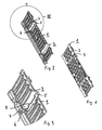
- Fig. 1 shows a cover 1 of a drainage channel not shown here, wherein the cover 1 is provided in the present case with linear drainage holes 2.
- the cover 1 is provided in the present case with linear drainage holes 2.
- it is a so-called web-cast cover, as used for example in the heavy load range.
- web-cast covers are usually included in the frame region of a concrete channel, which is not shown here in a line drainage or a concrete shaft at a point drainage.
- Fig. 1 can be removed, at least two of the line-like drainage openings 2 lighting elements 3 are assigned.
- the lighting element 3 consists, as shown in FIG Fig. 2 , which shows the web-cast cover in a bottom view, of a transparent plastic body 4, which is engaged by a fastening device 5.
- an elastically resilient sheet metal web is provided as a fastening device 5, which can be clipped with the cover 1 as intended.
- the clip connection shown represents a possible detachable connection between the cover 1 and the lighting element 3.
- the fastening lugs 6 of the fastening device 5 designed as clip connections can thus be opened again without any problems, eg if a different lighting image is desired. You can also be moved along the cover 1 under cross-longitudinal ridge and thus associated with another drainage opening 2.
- the fastening web 7 of the fastening device 5 engages under the plastic body 4 of the lighting element 3 positively.
- 7 side tabs 8 are integrally formed on the fastening web, between which the filament 4 is received positively.
- the lighting element 3 is an LED module which is cast in a plastic body 4 functioning as a luminous element.
- the plastic as well as the fastening device 5 is elastically deformable, so that in the case of overrunning the cover 1 and the extent resulting deflection of the cover 1 as well as the associated with this lighting element 3 the extent acting forces absorbed and derived by elastic deformation.
- the arrangement and attachment of the lighting element 3 is in the partial view in Fig. 3 shown in detail.
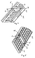
- FIG. 4 shows the bottom view of a formed as BlechSteg cover 1, which is again associated with a lighting element 3, which comprises a plastic body 4 and a fastening device 5. Unlike the one from the Fig.
- the fastening web 7 of the fastening device 5 is not verklippst with the cover 1, but jammed by the over the filament 4 protruding lateral fixing webs 7 are resilient and can be compressed so that a shortening of the longitudinal extent of the fastening device 5 occurs, to position in this state, the fastening device 5 with the plastic body 4 received therein below the cover 1 so that the plastic body 4 is assigned to a predetermined drainage opening 2, and then release the fastening web 7 again, then in full longitudinal extent is clamped with corresponding side flanges 10 of the cover 1.
- the lighting element 3 as shown in FIG Fig. 5 be associated with a cast grate.
- the plastic body 4 is again attacked by the fastening web 7 of the fastening device 5, wherein the protruding over the plastic body 4 mounting tabs 6 are bolted directly to the cover 1 in this case.
- the screw 11 is carried out directly with the casting of acting as a cover 1 grid.
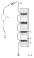
- a plurality of interconnected lighting elements 3 a single cover 1 be assigned.
- the connectors 12 used in this case are waterproof screwed and can therefore be installed without problems in the drainage channel.
- the optionally connected in series or parallel lighting elements 3 are connected to a common power supply 13. This is a low voltage network supplied by a conventional power supply 13.
- the individual lighting elements 3 can also be embodied as multi-colored lighting modules which can cover the entire color spectrum red / green / blue, for example in the LED range, so that virtually any desired color can be set by means of the control, and as a group or be controlled separately.
- RGB controller For the purpose of driving a not shown here RGB controller is used.
- the above illumination examples thus show that the lighting element 3 according to the invention can be used without problems in connection with most diverse covers 1. Due to the special design of an elastically deformable lighting device, the additional assignment of a lighting device, which can also be retrofitted, without any limitation to the load capacity and thus the scope of the corresponding upgraded drainage device is possible. Due to the use of special suitable materials, the light elements are resistant to high pressure cleaners and UV-resistant. Special receptacles or ancillary structures are not required in the case of retrofit or equipment with corresponding lighting elements 3.
- both existing drainage devices can be retrofitted with the lighting device according to the invention or factory already equipped with it.
Abstract
Description
Die Erfindung betrifft eine Entwässerungsvorrichtung zur Punkt- oder Linienentwässerung von vorzugsweise versiegelten Oberflächen, wobei die Entwässerungsvorrichtung einen Entwässerungskörper und eine Abdeckung mit Entwässerungsöffnungen umfasst und in diese Entwässerungsvorrichtung zumindest ein Beleuchtungselement integriert ist, welches mittels einer Befestigungsvorrichtung derart unterhalb der Abdeckung der Entwässerungsvorrichtung befestigt ist, dass durch eine oder mehrere der Entwässerungsöffnungen der Abdeckung Licht emittiert wird.The invention relates to a drainage device for spot or line drainage of preferably sealed surfaces, wherein the drainage device comprises a drainage body and a cover with drainage openings and at least one lighting element is integrated into this drainage device, which is fastened below the cover of the drainage device by means of a fastening device is emitted by one or more of the drainage openings of the cover light.
Eine solche Entwässerungsvorrichtung ist etwa aus der
Eine ähnlich Entwässerungsvorrichtung ist etwa aus der
In bevorzugter Ausgestaltung ist die Haltevorrichtung für den in die Entwässerungsvorrichtung integrierten Beleuchtungskörper mit einer Abdeckung zur wasserdichten Abkapselung des Beleuchtungskörpers versehen, um das Eindringen des zu entwässernden Oberflächenwassers in den Beleuchtungskörper zu verhindern. Zum Zwecke der Stromzuführung können gesonderte Stützkörper im Inneren der Rinne verlegt sein, oder es können alternativ im Falle des Einsatzes der Beleuchtungselemente in Entwässerungsrinnen, die für hohe Belastungsklassen ausgelegt sind, auch die Zargen zur Auflage der Abdeckung als Stromzuführungsvorrichtung eingesetzt werden.In a preferred embodiment, the holding device for the integrated in the dewatering device lighting fixture is provided with a cover for waterproofing of the lighting fixture to prevent the penetration of the surface water to be drained into the lighting fixture. For the purpose of power supply separate support body may be installed inside the gutter, or it may alternatively in the case of use of the lighting elements in drainage channels, which are designed for high load classes, and the frames for Edition of the cover can be used as a power supply device.
Aus der
Auch in der
Es besteht also zweifellos ein Bedarf an der durch die in die Entwässerungsvorrichtung integrierte Beleuchtungsvorrichtung geschaffenen Doppelfunktion der Entwässerungsrinne, also dass neben die Entwässerungsfunktion eine Beleuchtungs- und Markierungsfunktion oder auch ein Design-Element tritt. Allerdings müssen die genannten Beleuchtungselemente auch den zum Teil rauen Umgebungsbedingungen entsprechend ausgebildet sein und versagens- und zerstörungsfrei, gerade im Bereich der Entwässerung von Verkehrsflächen, auch dann zuverlässig funktionieren, wenn die Entwässerungsrinnen entweder bestimmungsgemäß oder zumindest zeitweise vom Straßenverkehr überfahren werden.There is thus clearly a need for the double function of the drainage channel created by the lighting device integrated in the dewatering device, ie, in addition to the dewatering function, a lighting and marking function or even a design element occurs. However, the lighting elements mentioned must also be designed in accordance with the sometimes harsh environmental conditions and function reliably without failure and destruction, especially in the area of drainage of traffic areas, if the drainage channels are either overrun or at least temporarily run over by traffic.
Der Erfindung liegt hiervon ausgehend die Aufgabe zu Grunde, eine beleuchtbare Entwässerungsvorrichtung zu schaffen, die im Schwerlastbereich, also auch im Bereich der Entwässerung von Verkehrsflächen, eingesetzt werden kann. Die Lösung dieser Aufgabe gelingt mit einer Entwässerungsvorrichtung gemäß den Merkmalen des Hauptanspruchs. Vorteilhafte Ausgestaltungen der Erfindung können den abhängigen Ansprüchen 2 bis 15 entnommen werden.On this basis, the invention is based on the object of providing an illuminable drainage device which is used in the heavy-load sector, ie also in the area of drainage of traffic areas can. The solution of this problem is achieved with a dewatering device according to the features of the main claim. Advantageous embodiments of the invention can be taken from the
Dadurch, dass der Entwässerungsvorrichtung eine Beleuchtungsvorrichtung zugeordnet ist, die sich dadurch auszeichnet, dass sie mittels einer elastisch verformbaren Befestigungsvorrichtung mit der Abdeckung einer Entwässerungsvorrichtung integrierbar ist und überdies auch das Beleuchtungselement als solches mit einem elastisch verformbaren Kunststoffkörpers vergossen ist, können etwaige elastische Verformungen, insbesondere der Abdeckung der Entwässerungsvorrichtung, durch eine korrespondierende kraft- und formschlüssige Verformung des Kunststoffkörpers und der Befestigungsvorrichtung aufgenommen und insoweit zerstörungs- und versagensfrei überstanden werden. Das Beleuchtungselement ist demnach federnd in die besagte Abdeckung integriert und unmittelbar unterhalb der Abdeckung befestigt. Hierdurch wird auch dem Problem begegnet, dass wenn beim Überfahren der Abdeckung Fremdkörper, etwa Kieselsteine, auf das Beleuchtungselement gedrückt werden, diesen einfach unter Ausnutzung des Federwegs des Befestigungselements ausgewichen werden kann.Characterized in that the dewatering device is associated with a lighting device, which is characterized in that it can be integrated by means of an elastically deformable fastening device with the cover of a dewatering device and, moreover, the lighting element is cast as such with an elastically deformable plastic body, any elastic deformations, in particular the cover of the dewatering device, received by a corresponding positive and positive deformation of the plastic body and the fastening device and in this respect survived destructive and failure-free. The lighting element is thus resiliently integrated into the said cover and fixed immediately below the cover. As a result, the problem is encountered that when driving over the cover foreign matter, such as pebbles, are pressed onto the lighting element, this can be avoided by simply using the spring travel of the fastener.
Durch die elastische Ausgestaltung des Beleuchtungselementes insgesamt können die beleuchteten Rinnen auch im Schwerlastbereich, also zur Entwässerung von Verkehrsflächen, eingesetzt werden. Dies ist insbesondere deshalb bedeutsam, weil die Markierungs- und Leitungsfunktion der beleuchteten Rinnen insbesondere im Verkehrsbereich sinnvoll ist.Due to the elastic configuration of the lighting element as a whole, the illuminated channels can also be used in the heavy-duty area, ie for drainage of traffic areas. This is particularly important because the marking and guiding function of the illuminated gutters makes sense, especially in the traffic sector.
Auf Grund dieser Ausgestaltung können die Beleuchtungselemente direkt mit der Abdeckung verbunden werden, also direkt unterhalb der Abdeckung angeordnet werden, so dass das von dem Beleuchtungselement emittierte Licht durch die Entwässerungsöffnung der Abdeckung austritt. Im Falle einer Befestigung der Beleuchtungselemente direkt unmittelbar unterhalb der Abdeckung ist der Lichteffekt am eindrucksvollsten, da ansonsten ein Großteil des Beleuchtungseffektes sinnloser Weise innerhalb der Rinne mehr oder minder unsichtbar infolge Verschmutzung vergeudet wird.Due to this configuration, the lighting elements can be connected directly to the cover, that is to be arranged directly below the cover, so that the light emitted by the lighting element exits through the drainage opening of the cover. In the case of attachment of the lighting elements directly below the cover, the lighting effect is most impressive, otherwise a large part of the lighting effect is uselessly wasted in the gutter more or less invisible due to pollution.
Ein weiterer Beitrag zur Erhöhung der Effizienz des eingesetzten Leuchtelementes, aber auch im Hinblick auf die geforderte Robustheit der Einrichtung ist es, dass das Leuchtelement des Beleuchtungselementes ein LED-Modul ist, das in einen transparenten Kunststoffkörper eingegossen ist, wobei der Kunststoffkörper die verlangte elastische Verformbarkeit besitzt. Durch die entsprechende Werkstoffauswahl des Kunststoffes, also insbesondere des Elastizitätsmoduls, kann das Beleuchtungselement an die jeweiligen Anforderungen ideal angepasst werden. Der Kunststoffkörper ist darüber hinaus idealerweise transparent oder opak ausgebildet und wasserdicht sowie resistent gegen gegebenenfalls einwirkende aggressive Umweltmedien.Another contribution to increasing the efficiency of the luminous element used, but also with regard to the required robustness of the device is that the luminous element of the lighting element is an LED module which is cast in a transparent plastic body, wherein the plastic body the required elastic deformability has. Through the appropriate choice of material of the plastic, so in particular the modulus of elasticity, the lighting element can be ideally adapted to the particular requirements. In addition, the plastic body is ideally transparent or opaque and waterproof and resistant to any potentially aggressive environmental media.
Über den Kunststoffkörper des eingesetzten Beleuchtungselements kann eine ideale Anpassung des Beleuchtungselementes an die Entwässerungsöffnungen der Abdeckung erfolgen, so dass auch insoweit eine optimale Abstimmung von Beleuchtungselement und Abdeckung gewährleistet ist.By way of the plastic body of the lighting element used, an ideal adaptation of the lighting element to the drainage openings of the cover can take place, so that optimum matching of lighting element and cover is ensured in this respect as well.
Die Beleuchtungselemente sind bedarfsweise für den Innen- oder Außenbereich ausgelegt, also vorzugsweise witterungsfest ausgebildet.The lighting elements are, if necessary, designed for indoor or outdoor use, so preferably formed weatherproof.
Im Einbauzustand wird dieser Kunststoffkörper von einem ebenfalls elastisch verformbaren Befestigungssteg, der etwa aus Metall, insbesondere aus Blech gefertigt sein kann, untergriffen, wobei dieser Befestigungssteg mittels über den Leuchtkörper überstehender Befestigungslaschen mit der Abdeckung verschraubt oder verklemmt ist. Darüber hinaus besitzt der Befestigungssteg den Leuchtkörper zumindest teilweise seitlich einfassende Befestigungsstege, so dass im Ergebnis der Kunststoffkörper als Gehäuse des Beleuchtungselementes formschlüssig mit dem Befestigungssteg verbunden ist. Der Befestigungssteg ist federnd ausgebildet, so dass einwirkende Belastungen federnd ausgeglichen werden.In the installed state of this plastic body of a likewise elastically deformable fastening web, which may be made of metal, in particular made of sheet metal, under attack, said fastening web is screwed or clamped by means of over the filament protruding mounting tabs with the cover. In addition, the fastening web has the luminous body at least partially laterally enclosing fastening webs, so that as a result of the plastic body is connected as a housing of the lighting element form-fitting manner with the fastening web. The fastening web is resilient, so that acting loads are resiliently compensated.
Die insoweit verbundene Einheit von Beleuchtungselement und Befestigungsvorrichtung ist also eine in sich elastisch verformbare Einheit, so dass im Einbauzustand etwa beim Überfahren einer Abdeckung einwirkende Verformungsenergie durch elastische Verformung des Beleuchtungselementes und/oder der Befestigungsvorrichtung insgesamt aufgenommen wird. Dies gilt gleichermaßen für senkrecht einwirkende Oberflächenlasten wie auch für etwa seitlich einwirkende Schublasten, wie sie typischerweise beim Überfahren oder bei Bremsvorgängen derartiger Entwässerungsvorrichtungen auftreten.The extent associated unit of lighting element and fastening device is thus an elastically deformable in itself unit, so that in the installed state about when overpassing a cover acting deformation energy is absorbed by elastic deformation of the lighting element and / or the fastening device as a whole. This applies equally to vertically acting surface loads as well as to approximately laterally acting thrust loads, as they typically occur when driving over or during braking of such drainage devices.
Durch die Ausformung des Leuchtkörpers kann je nach Anforderung das Beleuchtungselement wahlweise bündig mit der Oberfläche der Abdeckung der Entwässerungsvorrichtung abschließen, tiefergelegt sein oder bedarfsweise auch überstehen. Vorteilhaft ist eine bündige oder (leicht) überstehende Ausbildung des Beleuchtungselements, insbesondere für den Einsatz im Außenbereich, um Schmutzablagerungen auf den Beleuchtungselementen zu verhindern.Depending on the requirements, the lighting element can optionally be flush with the surface of the cover of the dewatering device due to the shape of the luminous element conclude, be inferior or, if necessary, survive. Advantageously, a flush or (slightly) protruding formation of the lighting element, in particular for use in the outdoor area to prevent dirt deposits on the lighting elements.
Bestimmungsgemäß können einer einzigen Entwässerungsvorrichtung oder Abdeckung auch mehrere Beleuchtungselemente zugeordnet sein, die dann wahlweise in Reihe oder parallel geschaltet sein können und mit einer gemeinsamen Stromversorgung und Steuerung verbunden sind. Bei einer derartigen Ausführung können auch spezielle Lichteffekte wie etwa ein Lauflicht zur Verbesserung der Leitfunktion erzeugt oder auch Design-Effekte wie unterschiedliche Lichtfarben umgesetzt werden. Dabei kann eine Einzelansteuerung der einzelnen Leuchtelemente oder auch eine Gruppenansteuerung bedarfsweise realisiert werden.As intended, a single dewatering device or cover can also be assigned a plurality of lighting elements, which can then optionally be connected in series or in parallel and are connected to a common power supply and control. In such an embodiment, special lighting effects such as a running light can be generated to improve the control function or design effects such as different light colors can be implemented. In this case, a single control of the individual lighting elements or a group control can be realized if necessary.
Im Falle mehrer Beleuchtungselemente, die einer Entwässerungsvorrichtung zugeordnet sind, kann die Beleuchtungsfunktion durch eine Leit- und Anzeigefunktion ergänzt sein, indem die Beleuchtungselemente zu ggf. sogar variierenden Symbolen, Zahlen oder Buchstaben verschaltet sind.In the case of several lighting elements, which are associated with a dewatering device, the lighting function can be supplemented by a guidance and display function by the lighting elements are interconnected to possibly even varying symbols, numbers or letters.
In vorteilhafter Ausgestaltung sind die einzelnen Leuchtelemente durch Steckverbinder miteinander verbunden, die wasserdicht steck- und/oder verschraubbar sind.In an advantageous embodiment, the individual lighting elements are connected to each other by connectors that are waterproof plug and / or screwed.
Fertigungstechnisch hat es sich als vorteilhaft erwiesen, wenn Entwässerungskörper und Abdeckung aus ein und dem selben Material hergestellt sind. In bevorzugter Ausführung ist die beleuchtete Entwässerungsvorrichtung als Schlitzrinne ausgebildet.Manufacturing technology, it has proved to be advantageous if drainage body and cover are made of one and the same material. In a preferred embodiment, the illuminated dewatering device is designed as a slot groove.
In besonders robuster Ausgestaltung ist das Beleuchtungselement als LED-Modul ausgebildet und in einem Kunststoffkörper vergossen, der seinerseits elastisch verformbar und/oder verschiebbar ist.In a particularly robust embodiment, the lighting element is designed as an LED module and cast in a plastic body, which in turn is elastically deformable and / or displaceable.
Dadurch, dass das Beleuchtungssystem mit der Abdeckung lösbar verbunden ist, kann mit der Abdeckung zugleich das Beleuchtungssystem entnommen werden. Hierdurch ist bedarfsweise eine ungehinderte Reinigung der Rinne möglich.
Die Erfindung wird anhand mehrerer in der Anlage nur schematisch dargestellter Ausführungsbeispiele näher erläutert.The fact that the lighting system is detachably connected to the cover, the illumination system can be removed with the cover at the same time. As a result, if necessary, an unhindered cleaning of the gutter is possible.
The invention will be explained in more detail with reference to several embodiments shown only schematically in the appendix.
Es zeigen
Figur 1- eine Abdeckung einer Entwässerungsvorrichtung im Schwerlastbereich mit dieser Abdeckung zugeordneten Beleuchtungselementen in einer Draufsicht,
Figur 2- die in
Fig. 1 gezeigte Abdeckung in teilperspektivischer Unteransicht, Figur 3- ein in
Figur 2Figs. 1 und 2 gezeigten Abdeckung, Figur 4- eine Blech-Stegabdeckung einer Entwässerungsvorrichtung mit einem zugeordneten Beleuchtungselement in einer teilperspektivischen Ansicht von unten,
Figur 5- eine Guss-Gitterrost-Abdeckung mit einem zugeordneten Beleuchtungselement in einer teilperspektivischen Ansicht von unten, und
Figur 6- ein Prinzipschaltbild zur Zusammenschaltung von mehreren einer einzigen Abdeckung zugeordneten Beleuchtungselementen.
- FIG. 1
- a cover of a drainage device in the heavy load area with lighting elements associated with this cover in a plan view,
- FIG. 2
- in the
Fig. 1 shown cover in partial perspective bottom view, - FIG. 3
- a in
FIG. 2 with III designated detail of the in theFigs. 1 and 2 shown cover, - FIG. 4
- a sheet metal web cover of a dewatering device with an associated lighting element in a partial perspective view from below,
- FIG. 5
- a cast grate cover with an associated lighting element in a partial perspective view from below, and
- FIG. 6
- a schematic diagram for the interconnection of a plurality of single cover associated lighting elements.
Wie ebenfalls
Das Beleuchtungselement 3 besteht gemäß der Darstellung in
Der Befestigungssteg 7 der Befestigungsvorrichtung 5 untergreift dabei den Kunststoffkörper 4 des Beleuchtungselementes 3 formschlüssig. Zusätzlich sind an den Befestigungssteg 7 Seitenlaschen 8 angeformt, zwischen denen der Leuchtkörper 4 formschlüssig aufgenommen ist.The
Bei richtigem Verständnis handelt es sich bei dem Beleuchtungselement 3 um ein LED-Modul, das in einen als Leuchtkörper fungierenden Kunststoffkörper 4 vergossen ist. Dabei ist der Kunststoff genauso wie die Befestigungsvorrichtung 5 elastisch verformbar ausgebildet, so das im Falle eines Überfahrens der Abdeckung 1 und der insoweit resultierenden Durchbiegung der Abdeckung 1 wie auch des mit dieser verbundenen Beleuchtungselementes 3 die insoweit einwirkenden Kräfte durch elastische Verformung aufgenommen und abgeleitet werden.If properly understood, the
Die Anordnung und Befestigung des Beleuchtungselementes 3 ist in der Teilansicht in
Eine alternative Ausgestaltung der Erfindung ist in
In abermals alternativer Ausgestaltung kann das Beleuchtungselement 3 gemäß der Darstellung in
Dabei können ergänzend zu den bereits gezeigten Ausführungsbeispielen gemäß dem Prinzipschaltbild in
Über die Spannungsversorgung können die einzelnen Beleuchtungselemente 3 gegebenenfalls auch als mehrfarbige Leuchtmodule ausgebildet sein, die etwa im LED-Bereich das gesamte Farbspektrum Rot/Grün/Blau abdecken können, so dass quasi im Wege der Ansteuerung jede beliebige Farbe einstellbar ist, und als Gruppe oder separat angesteuert sein.If necessary, the
Zum Zwecke der Ansteuerung wird ein hier nicht weiter dargestellter RGB-Controller eingesetzt.For the purpose of driving a not shown here RGB controller is used.
Im Ergebnis zeigen die vorstehenden Beleuchtungsbeispiele also, dass das erfindungsgemäße Beleuchtungselement 3 in Verbindung mit verschiedenartigsten Abdeckungen 1 unproblematisch eingesetzt werden kann. Auf Grund der speziellen Ausführung einer elastisch verformbaren Beleuchtungsvorrichtung ist die zusätzliche Zuordnung einer Beleuchtungsvorrichtung, die auch nachgerüstet werden kann, ohne jede Einschränkung für die Belastbarkeit und damit den Anwendungsbereich der entsprechend aufgerüsteten Entwässerungsvorrichtung möglich. Die Leuchtelemente sind auf Grund des Einsatzes von speziellen geeigneten Materialien hochdruckreinigerfest und UV-beständig. Spezielle Aufnahmevorrichtungen oder Zusatzkonstruktionen sind für den Fall der Nachrüstung oder Ausrüstung mit entsprechenden Beleuchtungselementen 3 nicht erforderlich.As a result, the above illumination examples thus show that the
Im Ergebnis können also sowohl bestehende Entwässerungsvorrichtungen mit der erfindungsgemäßen Beleuchtungsvorrichtung nachgerüstet werden oder werkseitig bereits damit ausgestattet sein.As a result, therefore, both existing drainage devices can be retrofitted with the lighting device according to the invention or factory already equipped with it.
- 11
- Abdeckungcover
- 22
- Entwässerungsöffnungdrainage opening
- 33
- Beleuchtungselementlighting element
- 44
- KunststoffkörperPlastic body
- 55
- Befestigungsvorrichtungfastening device
- 66
- Befestigungslaschenmounting tabs
- 77
- Befestigungsstegfastening web
- 88th
- Seitenlascheside flap
- 1111
- SchraubbefestigungScrew
- 1212
- SteckverbinderConnectors
- 1313
- Netzteilpower adapter
Claims (15)
dadurch gekennzeichnet, dass die Befestigungsvorrichtung (5) elastisch verformbar ist und bei Lasteinwirkung auf die Entwässerungsvorrichtung etwaige elastische Verformungen, insbesondere der Abdeckung (1), mittels kraft- und formschlüssiger Verformung der Befestigungsvorrichtung (5) des Beleuchtungselements (3) aufnehmbar sind.Dewatering device for point or line drainage of preferably sealed surfaces, wherein the dewatering device comprises a drainage body and a cover (1) with drainage openings (2) and in this dewatering device at least one lighting element (3) is integrated, which by means of a fastening device (5) below the cover (1) of the dewatering device is fastened so that light is emitted through one or more of the drainage openings (2) of the cover (1),
characterized in that the fastening device (5) is elastically deformable and upon load on the dewatering device any elastic deformations, in particular the cover (1), by means of non-positive and positive deformation of the fastening device (5) of the lighting element (3) are receivable.
Applications Claiming Priority (1)
| Application Number | Priority Date | Filing Date | Title |
|---|---|---|---|
| DE202009000014U DE202009000014U1 (en) | 2009-01-09 | 2009-01-09 | dehydrator |
Publications (2)
| Publication Number | Publication Date |
|---|---|
| EP2206832A2 true EP2206832A2 (en) | 2010-07-14 |
| EP2206832A3 EP2206832A3 (en) | 2011-11-30 |
Family
ID=40530999
Family Applications (1)
| Application Number | Title | Priority Date | Filing Date |
|---|---|---|---|
| EP10000132A Withdrawn EP2206832A3 (en) | 2009-01-09 | 2010-01-08 | Drainage device |
Country Status (2)
| Country | Link |
|---|---|
| EP (1) | EP2206832A3 (en) |
| DE (2) | DE202009000014U1 (en) |
Families Citing this family (6)
| Publication number | Priority date | Publication date | Assignee | Title |
|---|---|---|---|---|
| AT511519B1 (en) * | 2011-06-01 | 2013-12-15 | Alexander Mag Fh Peschke | CASE WITH A FOLDING FOOTBOARD |
| DE202011051310U1 (en) | 2011-09-15 | 2011-10-20 | Aco Severin Ahlmann Gmbh & Co. Kg | Shower channel with permanent lighting |
| FR2997994B1 (en) * | 2012-11-13 | 2015-07-17 | Gerard Charrier | SOLIDARIZED SUPPORT PART WITH AN EXTERIOR FRAMING COMPRISING A CANIVEAU AND A TRAPPE VISIT. |
| ITVR20130015A1 (en) * | 2013-01-23 | 2014-07-24 | Pircher S P A | PERFECT GRILL FOR SURFACE WATER TREATMENT. |
| DE202013012559U1 (en) | 2013-07-17 | 2017-06-27 | Hauraton Gmbh & Co. Kg | drainage channel |
| EP2826924A1 (en) | 2013-07-17 | 2015-01-21 | Hauraton GmbH & Co. KG | Drainage gutter with solar powered lighting |
Citations (3)
| Publication number | Priority date | Publication date | Assignee | Title |
|---|---|---|---|---|
| DE10355900B3 (en) * | 2003-11-29 | 2005-06-02 | Insta Elektro Gmbh | Building lighting device secured in rain gutter via integral spring arms of fixing clips for lamp housing |
| DE202008002774U1 (en) * | 2008-01-30 | 2008-06-19 | Aco Severin Ahlmann Gmbh & Co. Kg | Illuminated shower channel |
| DE102007057214A1 (en) * | 2007-11-28 | 2009-06-04 | Birco Baustoffwerk Gmbh | Drain gutter for discharging mud and/or water from e.g. lanes, has water channel, and illuminant e.g. red green blue LED, which is arranged at gutter or cover and extends along length of gutter, where cover overlies on inlet region |
Family Cites Families (1)
| Publication number | Priority date | Publication date | Assignee | Title |
|---|---|---|---|---|
| WO2006042694A1 (en) | 2004-10-18 | 2006-04-27 | Aco Severin Ahlmann Gmbh & Co. Kg | Drainage channel |
-
2009
- 2009-01-09 DE DE202009000014U patent/DE202009000014U1/en not_active Expired - Lifetime
-
2010
- 2010-01-08 EP EP10000132A patent/EP2206832A3/en not_active Withdrawn
- 2010-01-08 DE DE202010018063U patent/DE202010018063U1/en not_active Expired - Lifetime
Patent Citations (3)
| Publication number | Priority date | Publication date | Assignee | Title |
|---|---|---|---|---|
| DE10355900B3 (en) * | 2003-11-29 | 2005-06-02 | Insta Elektro Gmbh | Building lighting device secured in rain gutter via integral spring arms of fixing clips for lamp housing |
| DE102007057214A1 (en) * | 2007-11-28 | 2009-06-04 | Birco Baustoffwerk Gmbh | Drain gutter for discharging mud and/or water from e.g. lanes, has water channel, and illuminant e.g. red green blue LED, which is arranged at gutter or cover and extends along length of gutter, where cover overlies on inlet region |
| DE202008002774U1 (en) * | 2008-01-30 | 2008-06-19 | Aco Severin Ahlmann Gmbh & Co. Kg | Illuminated shower channel |
Also Published As
| Publication number | Publication date |
|---|---|
| DE202010018063U1 (en) | 2013-12-02 |
| DE202009000014U1 (en) | 2009-04-09 |
| EP2206832A3 (en) | 2011-11-30 |
Similar Documents
| Publication | Publication Date | Title |
|---|---|---|
| DE102007056600B4 (en) | Photovoltaic system with a matrix of frameless solar modules | |
| EP2206832A2 (en) | Drainage device | |
| EP1918480B1 (en) | Handrail with electric illumination sources provided in the handrail | |
| DE202006020571U1 (en) | Stable light for firing a tower | |
| DE102016220478A1 (en) | Elongated clamping unit | |
| DE102012025222A1 (en) | Toilet seat | |
| DE202008004786U1 (en) | Modular light band | |
| WO2006042694A1 (en) | Drainage channel | |
| EP3543420B1 (en) | Profile system with a light holding rail | |
| EP0877198A2 (en) | Lighting apparatus | |
| EP3524880A1 (en) | Eave profile, terrasse covering | |
| EP1182306A2 (en) | Connection system for wall elements on building walls | |
| CH697355B1 (en) | Door seal. | |
| DE102006022211B4 (en) | Backlit wall element system | |
| DE202004011168U1 (en) | Paving stone lamp for ground, wall and ceiling installation has transparent cover | |
| DE202011051310U1 (en) | Shower channel with permanent lighting | |
| DE19524103A1 (en) | Hollow column for mounting electrical measurement and control components e.g. for sewage- and chemical-plants, and pumping stations - uses several elements fitting together with tongue-groove connectors and screws in corners, plus detachable foot-plate and lid | |
| DE102007049532A1 (en) | Light for insertion into floor tile of bathroom, has transparent locking disk that is provided with sealing ring that causes sealing between locking disk and delimitation surface of recess of floor tile, which partially accommodates light | |
| AT11153U1 (en) | ILLUMINATED SHOWER | |
| EP2330342A2 (en) | Light with light housing and fixing element attached to the outside | |
| EP2761114B1 (en) | Water basin with illuminated edge stones | |
| DE202010012662U1 (en) | floor lamp | |
| DE10219570B4 (en) | Ventilation valve for dirty water pipes | |
| DE202004017750U1 (en) | Escalator or moving walk | |
| DE102020101152A1 (en) | Method of forming a lamp |
Legal Events
| Date | Code | Title | Description |
|---|---|---|---|
| PUAI | Public reference made under article 153(3) epc to a published international application that has entered the european phase |
Free format text: ORIGINAL CODE: 0009012 |
|
| AK | Designated contracting states |
Kind code of ref document: A2 Designated state(s): AT BE BG CH CY CZ DE DK EE ES FI FR GB GR HR HU IE IS IT LI LT LU LV MC MK MT NL NO PL PT RO SE SI SK SM TR |
|
| AX | Request for extension of the european patent |
Extension state: AL BA RS |
|
| PUAL | Search report despatched |
Free format text: ORIGINAL CODE: 0009013 |
|
| AK | Designated contracting states |
Kind code of ref document: A3 Designated state(s): AT BE BG CH CY CZ DE DK EE ES FI FR GB GR HR HU IE IS IT LI LT LU LV MC MK MT NL NO PL PT RO SE SI SK SM TR |
|
| AX | Request for extension of the european patent |
Extension state: AL BA RS |
|
| RIC1 | Information provided on ipc code assigned before grant |
Ipc: F21S 8/00 20060101ALI20111021BHEP Ipc: F21V 21/00 20060101ALI20111021BHEP Ipc: F21V 33/00 20060101ALI20111021BHEP Ipc: E01C 11/22 20060101AFI20111021BHEP |
|
| 17P | Request for examination filed |
Effective date: 20120229 |
|
| 17Q | First examination report despatched |
Effective date: 20121218 |
|
| STAA | Information on the status of an ep patent application or granted ep patent |
Free format text: STATUS: THE APPLICATION IS DEEMED TO BE WITHDRAWN |
|
| 18D | Application deemed to be withdrawn |
Effective date: 20130629 |