EP2205448B1 - Retractable nib writing instrument - Google Patents
Retractable nib writing instrument Download PDFInfo
- Publication number
- EP2205448B1 EP2205448B1 EP08782200A EP08782200A EP2205448B1 EP 2205448 B1 EP2205448 B1 EP 2205448B1 EP 08782200 A EP08782200 A EP 08782200A EP 08782200 A EP08782200 A EP 08782200A EP 2205448 B1 EP2205448 B1 EP 2205448B1
- Authority
- EP
- European Patent Office
- Prior art keywords
- barrel
- instrument
- cap
- arm
- gear
- Prior art date
- Legal status (The legal status is an assumption and is not a legal conclusion. Google has not performed a legal analysis and makes no representation as to the accuracy of the status listed.)
- Not-in-force
Links
- 239000012530 fluid Substances 0.000 claims abstract description 5
- 238000004891 communication Methods 0.000 claims abstract description 4
- 230000008878 coupling Effects 0.000 claims description 10
- 238000010168 coupling process Methods 0.000 claims description 10
- 238000005859 coupling reaction Methods 0.000 claims description 10
- 239000002989 correction material Substances 0.000 claims description 5
- 239000003973 paint Substances 0.000 claims description 5
- 230000033001 locomotion Effects 0.000 description 4
- NJPPVKZQTLUDBO-UHFFFAOYSA-N novaluron Chemical compound C1=C(Cl)C(OC(F)(F)C(OC(F)(F)F)F)=CC=C1NC(=O)NC(=O)C1=C(F)C=CC=C1F NJPPVKZQTLUDBO-UHFFFAOYSA-N 0.000 description 4
- 230000008859 change Effects 0.000 description 3
- 238000001035 drying Methods 0.000 description 3
- 230000005484 gravity Effects 0.000 description 3
- 230000009471 action Effects 0.000 description 2
- 239000000853 adhesive Substances 0.000 description 2
- 230000001070 adhesive effect Effects 0.000 description 2
- 239000007788 liquid Substances 0.000 description 2
- 239000000463 material Substances 0.000 description 2
- BASFCYQUMIYNBI-UHFFFAOYSA-N platinum Chemical compound [Pt] BASFCYQUMIYNBI-UHFFFAOYSA-N 0.000 description 2
- 230000000087 stabilizing effect Effects 0.000 description 2
- 230000005540 biological transmission Effects 0.000 description 1
- 238000000151 deposition Methods 0.000 description 1
- 238000005516 engineering process Methods 0.000 description 1
- 230000007613 environmental effect Effects 0.000 description 1
- 238000001704 evaporation Methods 0.000 description 1
- 230000008020 evaporation Effects 0.000 description 1
- 239000006260 foam Substances 0.000 description 1
- PCHJSUWPFVWCPO-UHFFFAOYSA-N gold Chemical compound [Au] PCHJSUWPFVWCPO-UHFFFAOYSA-N 0.000 description 1
- 239000010931 gold Substances 0.000 description 1
- 229910052737 gold Inorganic materials 0.000 description 1
- 239000000976 ink Substances 0.000 description 1
- 239000003550 marker Substances 0.000 description 1
- 230000007246 mechanism Effects 0.000 description 1
- 238000000034 method Methods 0.000 description 1
- 229910052697 platinum Inorganic materials 0.000 description 1
- 239000010970 precious metal Substances 0.000 description 1
- 238000007789 sealing Methods 0.000 description 1
- 239000000758 substrate Substances 0.000 description 1
Images






Classifications
-
- B—PERFORMING OPERATIONS; TRANSPORTING
- B43—WRITING OR DRAWING IMPLEMENTS; BUREAU ACCESSORIES
- B43K—IMPLEMENTS FOR WRITING OR DRAWING
- B43K5/00—Pens with ink reservoirs in holders, e.g. fountain-pens
- B43K5/02—Ink reservoirs
- B43K5/14—Exchangeable ink cartridges
-
- B—PERFORMING OPERATIONS; TRANSPORTING
- B43—WRITING OR DRAWING IMPLEMENTS; BUREAU ACCESSORIES
- B43K—IMPLEMENTS FOR WRITING OR DRAWING
- B43K23/00—Holders or connectors for writing implements; Means for protecting the writing-points
- B43K23/08—Protecting means, e.g. caps
- B43K23/12—Protecting means, e.g. caps for pens
- B43K23/126—Protecting means, e.g. caps for pens with clips
-
- B—PERFORMING OPERATIONS; TRANSPORTING
- B43—WRITING OR DRAWING IMPLEMENTS; BUREAU ACCESSORIES
- B43K—IMPLEMENTS FOR WRITING OR DRAWING
- B43K24/00—Mechanisms for selecting, projecting, retracting or locking writing units
- B43K24/02—Mechanisms for selecting, projecting, retracting or locking writing units for locking a single writing unit in only fully projected or retracted positions
- B43K24/06—Mechanisms for selecting, projecting, retracting or locking writing units for locking a single writing unit in only fully projected or retracted positions operated by turning means
-
- B—PERFORMING OPERATIONS; TRANSPORTING
- B43—WRITING OR DRAWING IMPLEMENTS; BUREAU ACCESSORIES
- B43K—IMPLEMENTS FOR WRITING OR DRAWING
- B43K25/00—Attaching writing implements to wearing apparel or objects involving constructional changes of the implements
- B43K25/02—Clips
- B43K25/028—Clips combined with means for propelling, projecting or retracting the writing unit
-
- B—PERFORMING OPERATIONS; TRANSPORTING
- B43—WRITING OR DRAWING IMPLEMENTS; BUREAU ACCESSORIES
- B43K—IMPLEMENTS FOR WRITING OR DRAWING
- B43K5/00—Pens with ink reservoirs in holders, e.g. fountain-pens
- B43K5/005—Pen barrels
-
- B—PERFORMING OPERATIONS; TRANSPORTING
- B43—WRITING OR DRAWING IMPLEMENTS; BUREAU ACCESSORIES
- B43K—IMPLEMENTS FOR WRITING OR DRAWING
- B43K5/00—Pens with ink reservoirs in holders, e.g. fountain-pens
- B43K5/16—Pens with ink reservoirs in holders, e.g. fountain-pens with retractable nibs
-
- B—PERFORMING OPERATIONS; TRANSPORTING
- B43—WRITING OR DRAWING IMPLEMENTS; BUREAU ACCESSORIES
- B43L—ARTICLES FOR WRITING OR DRAWING UPON; WRITING OR DRAWING AIDS; ACCESSORIES FOR WRITING OR DRAWING
- B43L19/00—Erasers, rubbers, or erasing devices; Holders therefor
- B43L19/0018—Erasers, rubbers, or erasing devices; Holders therefor with fluids
-
- B—PERFORMING OPERATIONS; TRANSPORTING
- B43—WRITING OR DRAWING IMPLEMENTS; BUREAU ACCESSORIES
- B43L—ARTICLES FOR WRITING OR DRAWING UPON; WRITING OR DRAWING AIDS; ACCESSORIES FOR WRITING OR DRAWING
- B43L19/00—Erasers, rubbers, or erasing devices; Holders therefor
- B43L19/0056—Holders for erasers
- B43L19/0068—Hand-held holders
Definitions
- the invention generally relates to a instrument according to the preamble of claim 1.
- Conventional writing instruments have a separate cap that protects the nib and prevents the writing instrument from drying out. Additionally, most conventional writing instrument caps have a clip that can be used to secure the writing instrument to another object when the writing instrument is not in use. For example, the clip may be used to secure the writing instrument in a shirt pocket. When the cap is removed in order to use the writing instrument, the cap is unattached and thus the cap is easily misplaced or lost, and the writing instrument becomes susceptible to drying out and cannot be attached to an object.
- U.S. 4,629,348 discloses a writing instrument having a barrel with a front opening that is covered by a sealing body.
- a writing member is disposed within the barrel and is movable within the barrel for advancing and retracting a writing tip.
- the writing member is advanced by a transmission mechanism disposed between the writing member and the barrel.
- DE 200 10 971 discloses a writing instrument having a top end and a bottom end.
- the writing instrument includes a cap attached to a bracket, the bracket being secured to the writing instrument body. As the bracket pivots the cap may be secured to either end of the writing instrument.
- DE 26 07 219 discloses ball point pen having two different color writing cartridges.
- a first color cartridge When a first color cartridge is moved into a writing position, a second color cartridge is automatically retracted.
- the first and second color cartridges move in opposite directions to one another during extension and/or retraction.
- Each color cartridge includes a toothed rack operatively coupled to opposite sides of a pinion for moving the cartridges in opposite directions.
- the invention provides an instrument according to claim 1. Preferred embodiments are disclosed in the subclaims.
- a writing instrument constructed in accordance with the teachings of the disclosure includes a barrel having a hollow channel, an open end and a closed end.
- a cartridge is slidably movable in the hollow channel and the cartridge has a nib in fluid communication with a reservoir.
- An arm is pivotably mounted to the barrel and a cap is attached to the arm, the cap is adapted to close the open end of the barrel when the arm is in a closed position. As the arm pivots, moving the cap from the closed position to an open position, the cartridge extends toward the open end of the barrel and exposes the nib. When the arm is rotated approximately 180 degrees, the nib is fully extended and ready for use.
- the writing instrument described herein advantageously provides a cap which is not separable from the writing instrument.
- the cap is not easily misplaced or lost.
- the cartridge may be easily and quickly replaced as a unit thus reducing the chance of spilling ink during refill.
- the arms rotate away from the front end of the barrel where a user will generally hold the writing instrument.
- a gripping area on the front of the barrel may be kept free and unobstructed during use.
- the pivoting action of the arms coupled with the sliding action of the cartridge provide a well balanced writing instrument.
- the change in the center of gravity due to the rearward pivoting of the arms may be offset by a similar change in the center of gravity due to the forward sliding of the cartridge. In this way, the overall center of gravity of the instrument may be maintained throughout the range of motion of the arms.
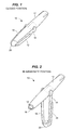
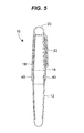
- Fig. 1 is a perspective view of a writing instrument constructed in accordance with the disclosure, the writing instrument being in a closed condition;
- Fig. 2 is a perspective view of the writing instrument of Fig. 1 in a partially open condition
- Fig. 3 is a perspective view of the writing instrument of Fig. 1 in a fully open position
- Fig. 4 is perspective partially cutaway and exploded view of the writing instrument of Fig. 1 ;
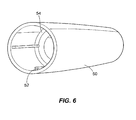
- Fig. 5 is a longitudinal cut away view of the barrel, arms and cap of the writing instrument of Fig. 1 ;
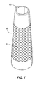
- Fig. 6 is a perspective view of a bottom portion of the barrel of the writing instrument of Fig. 1 ;
- Fig. 7 is a perspective view of a top portion of the barrel of the writing instrument of Fig. 1 ;
- Fig. 8 is a bottom perspective view of a coupler assembly that connects the top and bottom portions of the barrel of the writing instrument of Fig. 1 ;
- Fig. 9 is a top perspective view of the coupler assembly of Fig. 8 ;
- Fig. 10 is a perspective view of the arms of the writing instrument of Fig. 1 ;
- Fig. 11 is a perspective view of one of the arms of Fig. 10 ;
- Fig. 12 is another perspective view of the arm of Fig. 11 ;
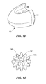
- Fig. 13 is a perspective view of the cap of the writing instrument of Fig. 1 ;
- Fig. 14 is a perspective view of a gear that connects an arm to the ink cartridge of the writing instrument of Fig. 1 ;
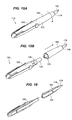
- Figs 15A and 15B are perspective views of an alternate embodiment of a writing instrument constructed in accordance with the teachings of the disclosure.
- Fig. 16 is a cut-away perspective view of the writing instrument of Figs. 15A and 15B ;
- Figs. 17A-17D are perspective cut-away views of the front barrel of the writing instrument of Figs. 15A and 15B during changing of the ink reservoir;
- Figs. 18A and 18B are close up partially cut-away views of a portion of the rear barrel of the writing instrument of Figs. 15A and 15B showing a slot and an internal stop;
- Fig. 19 is an exploded perspective view of the arms, clip and cap of the writing instrument of Figs. 15A and 15B .
- a fountain pen 10 is exemplified in the drawings, however, other writing instruments including, but not limited to markers, highlighters, ball pens, felt tip pens, and other fluid application devices including, but not limited to, correction fluid applicators and paint applicators could also be made in accordance with the teachings of the disclosure by selection of appropriate components. Similarly, other types of tools such as utility blades, screw drivers, punches, flashlights, etc., may be constructed in accordance with the teachings of the disclosure by substituting a tool for a nib.
- the fountain pen 10 comprises an outer hollow barrel 12 having an opening 14 at one end thereof through which a nib 16 extends and retracts.
- First and second arms 18 are rotatably attached to the outer barrel 12.
- a cap 20 is attached to the first and second arms 18.
- the nib 16 extends and retracts through the opening 14 as a result of a pivoting movement of the first and second arms 18.
- a clip 22 may be attached to one of the first and second arms 18 to attach the fountain pen 10 to an object, such as a shirt pocket, when the fountain pen 10 is not in use.
- Fig. 1 is a perspective view of the fountain pen 10 with the cap 20 and first and second arms 18 in a closed, capped position.
- the nib 16 (not shown in Fig. 1 ) retracts within the outer barrel 12 and the cap 20 covers and seals the opening 14.
- the cap 20 prevents evaporation of ink from the fountain pen 10 (i.e., "drying-out" of the fountain pen).
- the cap 20 also protects the nib 16 from environmental damage in the closed, capped position.
- Fig. 2 is a perspective view of the fountain pen 10 with the cap 20 and first and second arms 18 in an intermediate position. As the cap 20 and first and second arms 18 pivot away from the closed, capped position of Fig. 1 towards an open, writing position (shown in Fig. 3 ), the nib 16 begins to extend through the opening 14. The nib 16 extends at a rate proportional to the rotation of the first and second arms 18.
- Fig. 3 is a perspective view of the fountain pen 10 with the cap 20 and first and second arms 18 in the open, writing position.
- the nib 16 In the open, writing position, the nib 16 is fully extended through the opening 14 and the arms are approximately 180 degrees rotated from the closed, capped position of Fig. 1 .
- the open, writing position shown in Fig. 3 is a position where the nib 16 is accessible for writing.
- the nib 16 comprises a fountain pen nib having an angular flexible section that terminates in a ball-like tip.
- the fountain pen nib may be made from precious metals such as gold, platinum, and the like as is known in the art.
- the nib 16 is not limited to a fountain pen nib and may include writing instrument nibs of any sort.
- a ball point or maker nib could be employed.
- a brush applicator or a foam applicator could be used in combination with a correction fluid or paint applicator, of course, marker type applicators could be used with such correction fluid and paint applicators.
- Fig. 4 shows an exploded perspective view of the fountain pen 10. In this view, only one half of the outer barrel 12 is shown. The non shown half of the outer barrel 12 is a mirror image of the half shown.
- the nib 16 is attached to an ink cartridge 24 that includes a reservoir (not shown).
- the reservoir may hold ink, correction fluid, paint, etc. depending on the type of writing instrument and/or marking device employed. Additionally, the reservoir may be any type of liquid reservoir.
- the reservoir may be a free ink reservoir (for fountain pens, markers, felt tip pens, etc.), a fibrous reservoir (for markers, etc.), a tube reservoir with a follower (for ball pens), a cartridge reservoir, or any other known liquid reservoir.
- ink from an ink reservoir is fluidly connected to the nib 16.
- the ink cartridge 24 includes a sleeve 26 that is disposed around an outer surface of the ink cartridge 24.
- the sleeve 26 completely surrounds a portion of the ink cartridge 24.
- the sleeve 26 may comprise one or more partial sleeves 26 that may or may not completely surround the ink cartridge 24.
- the sleeve 26 may also be integral with the ink cartridge 24 if desired.
- the sleeve 26 includes a plurality of teeth 28 that mesh with teeth on one or more gears 30 disposed inside the outer barrel 12. In the embodiment of Fig.
- the sleeve has two sets of sleeve teeth 28 (one is hidden on the far side of the sleeve in Fig. 4 ). However, the sleeve may include only one set of sleeve teeth 28.
- the one or more gears 30 are connected to both of the first and second arms 18 respectively and rotate as the first and second arms 18 pivot. As the one or more gears 30 rotate, gear teeth 32 mesh with the sleeve teeth 28 thereby causing the sleeve 26 (and the ink cartridge 24) to slide longitudinally within the outer barrel 12.
- the fountain pen 10 includes a gear or gears 30 that are attached to only one arm.
- An annular shoulder 34 extends from an inner surface of the barrel 12.
- the shoulder 34 forms a stop which limits forward travel of the ink cartridge 24.
- the first and second arms 18 and gears 30 are arranged such that when the first and second arms 18 reach the open, writing position of Fig. 3 , the ink cartridge 24 reaches a fully forward travel location in which a front edge of the sleeve 26 abuts the shoulder 34 thereby stabilizing the ink cartridge 24 within the barrel 12.
- one or more shelves 36 extend from the inner surface of the barrel 12. The shelves 36 support and guide the ink cartridge 24 during extension and retraction.
- Fig. 5 shows a longitudinal cross section of the fountain pen 10.
- the first and second arms 18 are rotatably attached to the barrel 12 at respective hubs 40 that extend through the barrel 12.
- the hubs 40 may be connected to the gears 30 ( Fig. 4 ) by any known method such as press-fit, adhesives and/or fasteners.
- the clip 22 may be attached to one arm 18, or the clip 22 may be integrally formed with one arm 18.
- the outer barrel 12 may be formed in sections.
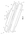
- Fig. 6 shows a rear barrel section 50.
- the rear barrel section 50 is a hollow tube that is closed at one end and open at another end.
- the rear barrel section 50 may include one or more ribs 52 and/or rings 54 to strengthen the rear barrel section 50 while reducing material required for the rear barrel section 50.
- Fig. 7 shows a front barrel section 60.
- the front barrel section 60 is a hollow tube, like the rear barrel section 50. However, the front barrel section 60 is open at both tube ends.
- the front barrel section 60 provides a gripping area 61 that may be covered by a comfortable gripping material if desired.
- the front barrel section 60 may taper from one end towards another end forming a gentle cone shape.
- one end of the front barrel section 60 may include an alignment shoulder 62.
- the alignment shoulder 62 cooperates with an alignment notch (discussed further hereinafter) on the cap 20 to properly align and seat the cap 20 on the front barrel section 60 when the cap 20 and first and second arms 18 are in the closed, capped position shown in Fig. 1 .
- the rear barrel section 50 and the front barrel section 60 may be connected to one another by a coupling section 70, which is shown in Figs. 8 and 9 .
- the coupling section 70 may include a center portion 72 and two end portions 74, the end portions 74 having a smaller outer diameter than the center portion 72.
- the end portions 74 may include one or more tabs 76. Alternately, the one or more tabs 76 may be joined to form a single annular flange (not shown).
- the one or more tabs 76 (or annular flanges) are inserted into the front barrel section 60 and the rear barrel section 50 respectively thereby joining both the front barrel section 60 and the rear barrel section 50 to the coupling section 70.
- the rear barrel section 50, front barrel section 60 and the coupling section 70 form the outer barrel 12.
- the coupling section may include one or more openings 76 that accommodate the hub 40 for the first and second arms 18.
- the openings 76 may be surrounded by a flange 78 and pedestal 80 if desired.
- the flange 78 and pedestal 80 cooperate with the first and second arms 18 to form a smooth appealing connection between the first and second arms 18 and the outer barrel 12 while allowing the first and second arms 18 to pivot with respect to the outer barrel 12.
- the flange 78 receives an axle (See Figs. 10-12 ) thereby aligning and stabilizing the arm about a pivot axis.
- the pedestal provides a locating surface to prevent the arms 18 from being pushed too far into the opening 76.
- Inner surfaces 82 of the one or more tabs 76 form generally planar guiding surfaces that corral the sleeve 26 and thus guide and support the ink cartridge 24 during longitudinal translation of the ink cartridge 24 within the barrel 12.
- Figs. 10-12 show the first and second arms 18 of the fountain pen 10.
- the first and second arms 18 are joined to one another at the cap 20. While the embodiment shown in Figs. 10-20 includes two arms 18, other embodiments may only include a single arm 18.
- each arm includes the hub 40.
- the hub 40 includes an annular shoulder surface 90 and an axle 92.
- Each axle 92 is inserted through one opening 76 in the coupling portion 70 and each axle 92 is connected to one gear 30 ( Fig. 4 ).
- the annular shoulder surface 90 abuts the pedestal 80 on the coupling section 70 to stabilize the first and second arms 18 in respective openings 76 and to prevent the arms 18 from being pushed too far into the openings 76.
- each arm includes a foot 94 that fits into a recess 96 ( Fig. 13 ) on the cap 20.
- the foot 94 may be secured to the cap 20 via any known means, such as, adhesives, fasteners, press-fit, etc.
- the cap may be integrally molded with one or both of the arms.
- Fig. 13 shows the cap 20.
- the cap 20 is generally conical in shape and includes two recesses 96 opposite one another. As discussed earlier, the recesses 96 receive the feet 94 of the first and second arms 18 thereby securing the first and second arms 18 to the cap 20. Additionally, the cap 20 may include a seal 98.
- the seal 98 may be disposed on an inner surface of the cap 20 or along the end of the cap 20. The seal 98 provides a substantially airtight fit between the cap 20 and the outer barrel 12 when the first and second arms 18 and cap 20 are in the closed, capped position shown in Fig. 1 , thus preventing ink in the fountain pen 10 from drying out when the fountain pen 10 is not in use.
- the cap includes an alignment notch that cooperates with the alignment shoulder 62 on the front barrel section 60. As the cap 20 is moved into the closed position of Fig. 1 , the alignment notch engages the alignment shoulder 62 to ensure proper alignment of the cap 20 on the front barrel section 60.
- Fig. 14 shows an example of the gear 30 that connects the first and second arms 18 to the sleeve 26.
- the gear 30 includes an outer plurality of teeth 32 and an inner plurality of teeth 32a.
- the inner plurality of teeth 32a are disposed about a circumference that is generally smaller than the circumference of the outer plurality of teeth 32.
- the ratio between the inner plurality of teeth 32a and the outer plurality of teeth 32 may be varied.
- the ratio may be approximately 1:2 between the inner plurality of teeth 32a and the outer plurality of teeth 32. Different ratios may provide faster or slower extension and retraction of the ink cartridge 24.
- a second gear may be added (not shown), which reverses the extension/retraction of the ink cartridge 24 relative to the direction of arm 18 movement.
- the outer plurality of teeth 32 and the inner plurality of teeth 32a may be disposed on separate gears 30.
- Figs. 15A and 15B show an example of a second embodiment of a writing instrument 110 constructed in accordance with the teachings of the disclosure, wherein like elements are labeled exactly 100 greater than corresponding elements of the embodiment shown in Figs. 1-14 .
- the writing instrument 110 comprises an outer hollow barrel 112 having an opening 114 at one end thereof through which a nib 116 extends and retracts.
- the outer hollow barrel 112 comprises a rear barrel section 150 and a front barrel section 160.
- the writing instrument 110 will be depleted of ink.
- An ink reservoir within the writing instrument 110 may be replaced when needed.
- the front barrel section 160 is rotated (as shown by the arrow in Fig. 15A ) to unlock the front barrel section 160 from the rear barrel section in order to facilitate changing of an ink reservoir.
- the front barrel section 160 is preferably rotated between approximately 90 degrees and approximately five full turns to unlock the front barrel section 160 from the rear barrel section 150. However, any number of turns, or fractions thereof, may be required to unlock the front and rear barrel sections 160, 150.
- the front barrel section 160 is moved away from the rear barrel section 150 as shown in Fig. 15B exposing the ink reservoir 125.
- the ink reservoir 125 is detachably connected to the nib 116.
- the nib 116 is in fluid communication with ink stored in the ink reservoir 125 and the ink stored in the ink reservoir 125 flows to the nib 116 for depositing on a substrate.
- the nib 116 is moved rearward, away from the opening 114 until the nib 116 contacts a rear edge of the front barrel section 160 ( Fig. 17B ), thereby forcing the ink reservoir 125 out of the back of the front barrel 160.
- the depleted ink reservoir 125 is removed from the nib 116 as shown in Fig. 17B .
- a fresh ink reservoir 125 is positioned within the front barrel 160 as shown in Fig. 17C .
- the fresh ink reservoir 125 pushes the nib 116 forward, towards the opening 114, until the nib 116 contacts a forward edge of the front barrel section 160 as shown in Fig. 17D .
- the fresh ink reservoir 125 is pushed towards the nib 116 to positively seat the fresh ink reservoir 125 on the nib 116, once again providing ink to the nib 116.
- 18A, 18B is disposed on an interior of the rear barrel section 150 and provides stops for the nib 116 during normal operation of the writing instrument 110 The stops prevent over-extension of the nib 116 and thus over-rotation of the arms 118.
- a post 117 disposed on the nib slidably engages within the channel 163 to limit forward and rearward movement of the nib 116.
- Fig. 19 shows an exploded view of the arms 118, clip 122 and cap 120a, 120b of the writing instrument 110 of Figs. 15A and 15B .
- the arms 118 are joined by a connecting portion 115 having an opening 119.
- other embodiments may include a one piece arm 118 or a two piece arm 118.
- the clip 122 likewise includes an opening 123.
- the cap 120 in this embodiment includes a first cap portion 120a and a second cap portion 120b.
- the first and second cap portions 120a, 120b also have openings.
- the second cap portion 120b includes a seal part 129 that cooperates with the opening 114 of the front barrel 160 to seal the nib 116 when the writing instrument is in the closed position.
- openings in the first cap portion 120a, clip 122, arms 118, and second cap portion 120b are aligned and a rivet 127 is inserted into the openings thereby securing the cap 120, clip 122 and arms 118 to one another.
- the disclosure is not limited to a fountain pen.
- the disclosure could be applied to virtually any writing instrument or tool, such as utility blades, flashlights, screw drivers, or other similar instruments.
Landscapes
- Engineering & Computer Science (AREA)
- Mechanical Engineering (AREA)
- Mechanical Pencils And Projecting And Retracting Systems Therefor, And Multi-System Writing Instruments (AREA)
- Pens And Brushes (AREA)
Applications Claiming Priority (2)
| Application Number | Priority Date | Filing Date | Title |
|---|---|---|---|
| US11/872,616 US8336583B2 (en) | 2007-10-15 | 2007-10-15 | Retractable nib writing instrument |
| PCT/US2008/070771 WO2009051873A1 (en) | 2007-10-15 | 2008-07-22 | Retractable nib writing instrument |
Publications (2)
| Publication Number | Publication Date |
|---|---|
| EP2205448A1 EP2205448A1 (en) | 2010-07-14 |
| EP2205448B1 true EP2205448B1 (en) | 2011-12-28 |
Family
ID=39847020
Family Applications (1)
| Application Number | Title | Priority Date | Filing Date |
|---|---|---|---|
| EP08782200A Not-in-force EP2205448B1 (en) | 2007-10-15 | 2008-07-22 | Retractable nib writing instrument |
Country Status (7)
| Country | Link |
|---|---|
| US (1) | US8336583B2 (cg-RX-API-DMAC10.html) |
| EP (1) | EP2205448B1 (cg-RX-API-DMAC10.html) |
| JP (1) | JP5497649B2 (cg-RX-API-DMAC10.html) |
| CN (1) | CN101821112B (cg-RX-API-DMAC10.html) |
| AT (1) | ATE538945T1 (cg-RX-API-DMAC10.html) |
| TW (1) | TW200927515A (cg-RX-API-DMAC10.html) |
| WO (1) | WO2009051873A1 (cg-RX-API-DMAC10.html) |
Families Citing this family (11)
| Publication number | Priority date | Publication date | Assignee | Title |
|---|---|---|---|---|
| CH704790C1 (fr) * | 2011-03-09 | 2017-03-15 | Swiss Finest S A | Instrument d’écriture à pointe rétractable. |
| US20140012205A1 (en) * | 2011-03-23 | 2014-01-09 | Sanofi-Aventis Deutschland Gmbh | Drug Delivery Device with Pivoting Protective Cap |
| CN102303468A (zh) * | 2011-06-07 | 2012-01-04 | 董德田 | 一种新型抗摔钢笔 |
| CN105690310A (zh) * | 2016-03-15 | 2016-06-22 | 中山纽创自动化科技有限公司 | 一种螺丝刀工具笔 |
| US10293630B2 (en) * | 2017-10-04 | 2019-05-21 | Alpha Engineering Works LLC | Spinning writing instruments |
| CN110328986B (zh) * | 2019-07-22 | 2020-08-11 | 温州市简系文具有限公司 | 一种伸缩笔 |
| USD1010003S1 (en) * | 2020-07-01 | 2024-01-02 | Sanford, L.P. | Writing instrument cap |
| CN114103527B (zh) * | 2020-08-31 | 2023-05-23 | 青岛点石文具用品有限公司 | 按压式书写文具 |
| CN112549820B (zh) * | 2020-12-14 | 2021-09-14 | 温州大学 | 一种防摔签字笔 |
| US12589176B2 (en) | 2021-10-29 | 2026-03-31 | Scentral Zone, Llc | Passive emission fragrance diffuser for personal use |
| CN116141850B (zh) * | 2021-11-22 | 2025-05-27 | 青岛点石文具用品有限公司 | 按动式书写笔 |
Family Cites Families (31)
| Publication number | Priority date | Publication date | Assignee | Title |
|---|---|---|---|---|
| US1615506A (en) * | 1925-12-08 | 1927-01-25 | George G Felt | Cap attachment for fountain pens |
| US1809416A (en) * | 1929-07-11 | 1931-06-09 | John G Liddell | Fountain pen |
| FR784223A (fr) * | 1934-09-15 | 1935-07-22 | Plume D Or | Porte-plume-réservoir |
| GB1064517A (en) * | 1963-11-27 | 1967-04-05 | Pilot Pen Co Ltd | Retractable nib fountain-pen |
| US3362778A (en) * | 1965-04-16 | 1968-01-09 | Pavese Angelo | Fountain pen |
| GB1095389A (cg-RX-API-DMAC10.html) * | 1966-02-25 | |||
| US3399778A (en) * | 1966-08-10 | 1968-09-03 | Laval Turbine | Filter apparatus having tubular filter medium |
| US3427112A (en) * | 1967-12-26 | 1969-02-11 | Pilot Pen Co Ltd | Capless fountain pen |
| DE2607219A1 (de) | 1976-02-23 | 1977-09-01 | Schaeffer Homberg Gmbh | Schreibgeraet mit laengsbeweglichen schreibeinheiten, insbesondere kugelschreiber |
| JPS57501274A (cg-RX-API-DMAC10.html) * | 1980-08-19 | 1982-07-22 | ||
| JPS5889399A (ja) * | 1981-11-20 | 1983-05-27 | 株式会社パイロット | ペン先出入万年筆の前端開口部開閉装置 |
| IT8223063U1 (it) * | 1982-09-30 | 1984-03-30 | Larizza & Scuratti | Strumento per scrittura o disegno |
| US4629348A (en) * | 1983-01-27 | 1986-12-16 | Ancos Co., Ltd. | Writing instrument with sealing cap and additional rearward seal |
| JPS6083583U (ja) * | 1983-11-16 | 1985-06-10 | 株式会社長谷川刃物製作所 | 有底収納部を設けた横止式収納具 |
| JPS6145071U (ja) * | 1984-08-24 | 1986-03-25 | 株式会社貝印刃物開発センター | ナイフ |
| JPH01118770U (cg-RX-API-DMAC10.html) * | 1988-02-03 | 1989-08-10 | ||
| JPH0273378U (cg-RX-API-DMAC10.html) * | 1988-11-25 | 1990-06-05 | ||
| JPH067989U (ja) * | 1992-07-08 | 1994-02-01 | 株式会社トンボ鉛筆 | ノック式マーカー筆記具 |
| US5352053A (en) * | 1993-07-08 | 1994-10-04 | Frederick Reitze | Writing instrument and cap |
| JP3668523B2 (ja) * | 1995-04-12 | 2005-07-06 | 三菱鉛筆株式会社 | キャップレス式筆記具 |
| JPH08332797A (ja) * | 1995-06-08 | 1996-12-17 | Takashi Yokoyama | リング付きキャップ |
| JP2673501B2 (ja) * | 1995-10-05 | 1997-11-05 | 巴豊 小林 | キャップ付き筆記具 |
| JP3042580U (ja) * | 1997-04-16 | 1997-10-21 | 有限会社テックメック | 持ち軸に取り付けられたままワンタッチで開閉されるキャップ |
| US6264080B1 (en) * | 1999-05-10 | 2001-07-24 | Stephan C. Ewing | Body mounted marker holder |
| JP2001252485A (ja) * | 2000-03-09 | 2001-09-18 | Daiwa Seiko Inc | ナイフ |
| DE20010971U1 (de) | 2000-06-21 | 2000-10-05 | TROIKA Böll GmbH & Co. KG, 57645 Nister | Schreibgerät |
| CN2508973Y (zh) * | 2001-11-27 | 2002-09-04 | 黄松朝 | 齿轮式笔芯尖随动伸缩笔 |
| AU2003230963B2 (en) * | 2002-04-17 | 2008-07-03 | Avery Dennison Corporation | Self-sealing retractable writing instrument |
| US7220073B2 (en) * | 2004-02-26 | 2007-05-22 | Morris Corporation | Slide-type writing instrument with a dry prevention unit |
| USD497644S1 (en) * | 2004-03-15 | 2004-10-26 | Sanford, L.P. | Correction marker |
| CN2858295Y (zh) * | 2006-01-05 | 2007-01-17 | 上海迈仕制笔有限公司 | 伸缩笔 |
-
2007
- 2007-10-15 US US11/872,616 patent/US8336583B2/en not_active Expired - Fee Related
-
2008
- 2008-07-22 EP EP08782200A patent/EP2205448B1/en not_active Not-in-force
- 2008-07-22 CN CN200880111531.0A patent/CN101821112B/zh not_active Expired - Fee Related
- 2008-07-22 AT AT08782200T patent/ATE538945T1/de active
- 2008-07-22 JP JP2010529993A patent/JP5497649B2/ja not_active Expired - Fee Related
- 2008-07-22 WO PCT/US2008/070771 patent/WO2009051873A1/en not_active Ceased
- 2008-08-11 TW TW097130570A patent/TW200927515A/zh unknown
Also Published As
| Publication number | Publication date |
|---|---|
| JP2011500371A (ja) | 2011-01-06 |
| JP5497649B2 (ja) | 2014-05-21 |
| US8336583B2 (en) | 2012-12-25 |
| EP2205448A1 (en) | 2010-07-14 |
| TW200927515A (en) | 2009-07-01 |
| CN101821112A (zh) | 2010-09-01 |
| US20090097906A1 (en) | 2009-04-16 |
| ATE538945T1 (de) | 2012-01-15 |
| CN101821112B (zh) | 2013-08-21 |
| WO2009051873A1 (en) | 2009-04-23 |
Similar Documents
| Publication | Publication Date | Title |
|---|---|---|
| US8336583B2 (en) | Retractable nib writing instrument | |
| EP1568510B1 (en) | Retractable writing instrument having a spherical door as a dry prevention unit | |
| US7147392B2 (en) | Combination writing instrument | |
| CA2710314C (en) | Adapter for writing instruments | |
| PH25975A (en) | Pen | |
| JP2011500371A5 (cg-RX-API-DMAC10.html) | ||
| JP2008260291A (ja) | 筆記用具 | |
| RU2350475C2 (ru) | Комбинированный пишущий инструмент | |
| US20060115314A1 (en) | Capless writing instrument with closing device | |
| US9452634B1 (en) | Writing instrument | |
| JPH0541918Y2 (cg-RX-API-DMAC10.html) | ||
| US20070110499A1 (en) | Dual-purpose pen for painting | |
| US5709491A (en) | Pencil-like eraser | |
| JP2566099Y2 (ja) | 複式筆記具 | |
| JP2002205493A (ja) | 複式筆記具 | |
| JPH0617591Y2 (ja) | 複式筆記具 | |
| JP2026004925A (ja) | 筆記具 | |
| JPH0679586U (ja) | 塗布具および塗布具のチップとコアとの接合構造 | |
| JPH1095194A (ja) | 液体塗布具 | |
| JPS60120889U (ja) | 複式筆記具 | |
| JP2007055029A (ja) | 芯先隠蔽式ボールペン | |
| JPH0939484A (ja) | 複式筆記具 | |
| JPH04135391U (ja) | 複式筆記具 | |
| JPH0939485A (ja) | 複式筆記具 |
Legal Events
| Date | Code | Title | Description |
|---|---|---|---|
| PUAI | Public reference made under article 153(3) epc to a published international application that has entered the european phase |
Free format text: ORIGINAL CODE: 0009012 |
|
| 17P | Request for examination filed |
Effective date: 20100406 |
|
| AK | Designated contracting states |
Kind code of ref document: A1 Designated state(s): AT BE BG CH CY CZ DE DK EE ES FI FR GB GR HR HU IE IS IT LI LT LU LV MC MT NL NO PL PT RO SE SI SK TR |
|
| AX | Request for extension of the european patent |
Extension state: AL BA MK RS |
|
| RIN1 | Information on inventor provided before grant (corrected) |
Inventor name: JACOBS, BARRY, H. Inventor name: BIELECKI, ANDREW |
|
| DAX | Request for extension of the european patent (deleted) | ||
| GRAP | Despatch of communication of intention to grant a patent |
Free format text: ORIGINAL CODE: EPIDOSNIGR1 |
|
| GRAS | Grant fee paid |
Free format text: ORIGINAL CODE: EPIDOSNIGR3 |
|
| GRAA | (expected) grant |
Free format text: ORIGINAL CODE: 0009210 |
|
| AK | Designated contracting states |
Kind code of ref document: B1 Designated state(s): AT BE BG CH CY CZ DE DK EE ES FI FR GB GR HR HU IE IS IT LI LT LU LV MC MT NL NO PL PT RO SE SI SK TR |
|
| REG | Reference to a national code |
Ref country code: GB Ref legal event code: FG4D |
|
| REG | Reference to a national code |
Ref country code: CH Ref legal event code: EP |
|
| REG | Reference to a national code |
Ref country code: AT Ref legal event code: REF Ref document number: 538945 Country of ref document: AT Kind code of ref document: T Effective date: 20120115 |
|
| REG | Reference to a national code |
Ref country code: IE Ref legal event code: FG4D |
|
| REG | Reference to a national code |
Ref country code: DE Ref legal event code: R082 Ref document number: 602008012378 Country of ref document: DE Representative=s name: BOEHMERT & BOEHMERT, DE Ref country code: DE Ref legal event code: R082 Ref document number: 602008012378 Country of ref document: DE Representative=s name: BOEHMERT & BOEHMERT ANWALTSPARTNERSCHAFT MBB -, DE |
|
| REG | Reference to a national code |
Ref country code: DE Ref legal event code: R096 Ref document number: 602008012378 Country of ref document: DE Effective date: 20120308 |
|
| REG | Reference to a national code |
Ref country code: NL Ref legal event code: VDEP Effective date: 20111228 |
|
| PG25 | Lapsed in a contracting state [announced via postgrant information from national office to epo] |
Ref country code: NO Free format text: LAPSE BECAUSE OF FAILURE TO SUBMIT A TRANSLATION OF THE DESCRIPTION OR TO PAY THE FEE WITHIN THE PRESCRIBED TIME-LIMIT Effective date: 20120328 Ref country code: LT Free format text: LAPSE BECAUSE OF FAILURE TO SUBMIT A TRANSLATION OF THE DESCRIPTION OR TO PAY THE FEE WITHIN THE PRESCRIBED TIME-LIMIT Effective date: 20111228 |
|
| LTIE | Lt: invalidation of european patent or patent extension |
Effective date: 20111228 |
|
| PG25 | Lapsed in a contracting state [announced via postgrant information from national office to epo] |
Ref country code: SE Free format text: LAPSE BECAUSE OF FAILURE TO SUBMIT A TRANSLATION OF THE DESCRIPTION OR TO PAY THE FEE WITHIN THE PRESCRIBED TIME-LIMIT Effective date: 20111228 Ref country code: GR Free format text: LAPSE BECAUSE OF FAILURE TO SUBMIT A TRANSLATION OF THE DESCRIPTION OR TO PAY THE FEE WITHIN THE PRESCRIBED TIME-LIMIT Effective date: 20120329 Ref country code: LV Free format text: LAPSE BECAUSE OF FAILURE TO SUBMIT A TRANSLATION OF THE DESCRIPTION OR TO PAY THE FEE WITHIN THE PRESCRIBED TIME-LIMIT Effective date: 20111228 Ref country code: HR Free format text: LAPSE BECAUSE OF FAILURE TO SUBMIT A TRANSLATION OF THE DESCRIPTION OR TO PAY THE FEE WITHIN THE PRESCRIBED TIME-LIMIT Effective date: 20111228 Ref country code: SI Free format text: LAPSE BECAUSE OF FAILURE TO SUBMIT A TRANSLATION OF THE DESCRIPTION OR TO PAY THE FEE WITHIN THE PRESCRIBED TIME-LIMIT Effective date: 20111228 |
|
| PG25 | Lapsed in a contracting state [announced via postgrant information from national office to epo] |
Ref country code: BE Free format text: LAPSE BECAUSE OF FAILURE TO SUBMIT A TRANSLATION OF THE DESCRIPTION OR TO PAY THE FEE WITHIN THE PRESCRIBED TIME-LIMIT Effective date: 20111228 Ref country code: CY Free format text: LAPSE BECAUSE OF FAILURE TO SUBMIT A TRANSLATION OF THE DESCRIPTION OR TO PAY THE FEE WITHIN THE PRESCRIBED TIME-LIMIT Effective date: 20111228 |
|
| PG25 | Lapsed in a contracting state [announced via postgrant information from national office to epo] |
Ref country code: NL Free format text: LAPSE BECAUSE OF FAILURE TO SUBMIT A TRANSLATION OF THE DESCRIPTION OR TO PAY THE FEE WITHIN THE PRESCRIBED TIME-LIMIT Effective date: 20111228 Ref country code: BG Free format text: LAPSE BECAUSE OF FAILURE TO SUBMIT A TRANSLATION OF THE DESCRIPTION OR TO PAY THE FEE WITHIN THE PRESCRIBED TIME-LIMIT Effective date: 20120328 Ref country code: EE Free format text: LAPSE BECAUSE OF FAILURE TO SUBMIT A TRANSLATION OF THE DESCRIPTION OR TO PAY THE FEE WITHIN THE PRESCRIBED TIME-LIMIT Effective date: 20111228 Ref country code: CZ Free format text: LAPSE BECAUSE OF FAILURE TO SUBMIT A TRANSLATION OF THE DESCRIPTION OR TO PAY THE FEE WITHIN THE PRESCRIBED TIME-LIMIT Effective date: 20111228 Ref country code: SK Free format text: LAPSE BECAUSE OF FAILURE TO SUBMIT A TRANSLATION OF THE DESCRIPTION OR TO PAY THE FEE WITHIN THE PRESCRIBED TIME-LIMIT Effective date: 20111228 Ref country code: IS Free format text: LAPSE BECAUSE OF FAILURE TO SUBMIT A TRANSLATION OF THE DESCRIPTION OR TO PAY THE FEE WITHIN THE PRESCRIBED TIME-LIMIT Effective date: 20120428 |
|
| PG25 | Lapsed in a contracting state [announced via postgrant information from national office to epo] |
Ref country code: RO Free format text: LAPSE BECAUSE OF FAILURE TO SUBMIT A TRANSLATION OF THE DESCRIPTION OR TO PAY THE FEE WITHIN THE PRESCRIBED TIME-LIMIT Effective date: 20111228 Ref country code: PT Free format text: LAPSE BECAUSE OF FAILURE TO SUBMIT A TRANSLATION OF THE DESCRIPTION OR TO PAY THE FEE WITHIN THE PRESCRIBED TIME-LIMIT Effective date: 20120430 Ref country code: PL Free format text: LAPSE BECAUSE OF FAILURE TO SUBMIT A TRANSLATION OF THE DESCRIPTION OR TO PAY THE FEE WITHIN THE PRESCRIBED TIME-LIMIT Effective date: 20111228 |
|
| REG | Reference to a national code |
Ref country code: AT Ref legal event code: MK05 Ref document number: 538945 Country of ref document: AT Kind code of ref document: T Effective date: 20111228 |
|
| PG25 | Lapsed in a contracting state [announced via postgrant information from national office to epo] |
Ref country code: DK Free format text: LAPSE BECAUSE OF FAILURE TO SUBMIT A TRANSLATION OF THE DESCRIPTION OR TO PAY THE FEE WITHIN THE PRESCRIBED TIME-LIMIT Effective date: 20111228 |
|
| PLBE | No opposition filed within time limit |
Free format text: ORIGINAL CODE: 0009261 |
|
| STAA | Information on the status of an ep patent application or granted ep patent |
Free format text: STATUS: NO OPPOSITION FILED WITHIN TIME LIMIT |
|
| PG25 | Lapsed in a contracting state [announced via postgrant information from national office to epo] |
Ref country code: IT Free format text: LAPSE BECAUSE OF FAILURE TO SUBMIT A TRANSLATION OF THE DESCRIPTION OR TO PAY THE FEE WITHIN THE PRESCRIBED TIME-LIMIT Effective date: 20111228 |
|
| 26N | No opposition filed |
Effective date: 20121001 |
|
| REG | Reference to a national code |
Ref country code: DE Ref legal event code: R097 Ref document number: 602008012378 Country of ref document: DE Effective date: 20121001 |
|
| PG25 | Lapsed in a contracting state [announced via postgrant information from national office to epo] |
Ref country code: AT Free format text: LAPSE BECAUSE OF FAILURE TO SUBMIT A TRANSLATION OF THE DESCRIPTION OR TO PAY THE FEE WITHIN THE PRESCRIBED TIME-LIMIT Effective date: 20111228 |
|
| PG25 | Lapsed in a contracting state [announced via postgrant information from national office to epo] |
Ref country code: MC Free format text: LAPSE BECAUSE OF NON-PAYMENT OF DUE FEES Effective date: 20120731 |
|
| REG | Reference to a national code |
Ref country code: CH Ref legal event code: PL |
|
| PG25 | Lapsed in a contracting state [announced via postgrant information from national office to epo] |
Ref country code: ES Free format text: LAPSE BECAUSE OF FAILURE TO SUBMIT A TRANSLATION OF THE DESCRIPTION OR TO PAY THE FEE WITHIN THE PRESCRIBED TIME-LIMIT Effective date: 20120408 Ref country code: CH Free format text: LAPSE BECAUSE OF NON-PAYMENT OF DUE FEES Effective date: 20120731 Ref country code: LI Free format text: LAPSE BECAUSE OF NON-PAYMENT OF DUE FEES Effective date: 20120731 |
|
| REG | Reference to a national code |
Ref country code: IE Ref legal event code: MM4A |
|
| PG25 | Lapsed in a contracting state [announced via postgrant information from national office to epo] |
Ref country code: FI Free format text: LAPSE BECAUSE OF FAILURE TO SUBMIT A TRANSLATION OF THE DESCRIPTION OR TO PAY THE FEE WITHIN THE PRESCRIBED TIME-LIMIT Effective date: 20111228 |
|
| PG25 | Lapsed in a contracting state [announced via postgrant information from national office to epo] |
Ref country code: IE Free format text: LAPSE BECAUSE OF NON-PAYMENT OF DUE FEES Effective date: 20120722 Ref country code: MT Free format text: LAPSE BECAUSE OF FAILURE TO SUBMIT A TRANSLATION OF THE DESCRIPTION OR TO PAY THE FEE WITHIN THE PRESCRIBED TIME-LIMIT Effective date: 20111228 |
|
| PG25 | Lapsed in a contracting state [announced via postgrant information from national office to epo] |
Ref country code: TR Free format text: LAPSE BECAUSE OF FAILURE TO SUBMIT A TRANSLATION OF THE DESCRIPTION OR TO PAY THE FEE WITHIN THE PRESCRIBED TIME-LIMIT Effective date: 20111228 |
|
| PG25 | Lapsed in a contracting state [announced via postgrant information from national office to epo] |
Ref country code: LU Free format text: LAPSE BECAUSE OF NON-PAYMENT OF DUE FEES Effective date: 20120722 |
|
| PG25 | Lapsed in a contracting state [announced via postgrant information from national office to epo] |
Ref country code: HU Free format text: LAPSE BECAUSE OF FAILURE TO SUBMIT A TRANSLATION OF THE DESCRIPTION OR TO PAY THE FEE WITHIN THE PRESCRIBED TIME-LIMIT Effective date: 20080722 |
|
| PGFP | Annual fee paid to national office [announced via postgrant information from national office to epo] |
Ref country code: DE Payment date: 20150729 Year of fee payment: 8 |
|
| REG | Reference to a national code |
Ref country code: FR Ref legal event code: PLFP Year of fee payment: 9 |
|
| REG | Reference to a national code |
Ref country code: DE Ref legal event code: R119 Ref document number: 602008012378 Country of ref document: DE |
|
| PG25 | Lapsed in a contracting state [announced via postgrant information from national office to epo] |
Ref country code: DE Free format text: LAPSE BECAUSE OF NON-PAYMENT OF DUE FEES Effective date: 20170201 |
|
| REG | Reference to a national code |
Ref country code: FR Ref legal event code: PLFP Year of fee payment: 10 |
|
| PGFP | Annual fee paid to national office [announced via postgrant information from national office to epo] |
Ref country code: FR Payment date: 20170726 Year of fee payment: 10 Ref country code: GB Payment date: 20170727 Year of fee payment: 10 |
|
| GBPC | Gb: european patent ceased through non-payment of renewal fee |
Effective date: 20180722 |
|
| PG25 | Lapsed in a contracting state [announced via postgrant information from national office to epo] |
Ref country code: GB Free format text: LAPSE BECAUSE OF NON-PAYMENT OF DUE FEES Effective date: 20180722 Ref country code: FR Free format text: LAPSE BECAUSE OF NON-PAYMENT OF DUE FEES Effective date: 20180731 |