EP2205162B1 - Dispositif de fixation extensible - Google Patents
Dispositif de fixation extensible Download PDFInfo
- Publication number
- EP2205162B1 EP2205162B1 EP08843886.6A EP08843886A EP2205162B1 EP 2205162 B1 EP2205162 B1 EP 2205162B1 EP 08843886 A EP08843886 A EP 08843886A EP 2205162 B1 EP2205162 B1 EP 2205162B1
- Authority
- EP
- European Patent Office
- Prior art keywords
- expandable
- attachment device
- radially
- section
- expandable attachment
- Prior art date
- Legal status (The legal status is an assumption and is not a legal conclusion. Google has not performed a legal analysis and makes no representation as to the accuracy of the status listed.)
- Active
Links
- 238000002513 implantation Methods 0.000 claims description 2
- 210000000988 bone and bone Anatomy 0.000 description 44
- 206010017076 Fracture Diseases 0.000 description 13
- 230000001054 cortical effect Effects 0.000 description 9
- 239000000945 filler Substances 0.000 description 9
- 239000000463 material Substances 0.000 description 8
- 238000000034 method Methods 0.000 description 8
- 239000003795 chemical substances by application Substances 0.000 description 7
- 210000001519 tissue Anatomy 0.000 description 7
- 210000003811 finger Anatomy 0.000 description 6
- 208000010392 Bone Fractures Diseases 0.000 description 5
- -1 polyethylene Polymers 0.000 description 5
- 229920000642 polymer Polymers 0.000 description 5
- 229910045601 alloy Inorganic materials 0.000 description 4
- 239000000956 alloy Substances 0.000 description 4
- 238000012800 visualization Methods 0.000 description 4
- 239000004098 Tetracycline Substances 0.000 description 3
- 239000004568 cement Substances 0.000 description 3
- 230000006835 compression Effects 0.000 description 3
- 238000007906 compression Methods 0.000 description 3
- 238000001727 in vivo Methods 0.000 description 3
- 230000033001 locomotion Effects 0.000 description 3
- 229910001000 nickel titanium Inorganic materials 0.000 description 3
- 229920006149 polyester-amide block copolymer Polymers 0.000 description 3
- 229920001343 polytetrafluoroethylene Polymers 0.000 description 3
- 239000004810 polytetrafluoroethylene Substances 0.000 description 3
- 239000004814 polyurethane Substances 0.000 description 3
- 229920002635 polyurethane Polymers 0.000 description 3
- 229930101283 tetracycline Natural products 0.000 description 3
- 229960002180 tetracycline Drugs 0.000 description 3
- 235000019364 tetracycline Nutrition 0.000 description 3
- 150000003522 tetracyclines Chemical class 0.000 description 3
- 102000008186 Collagen Human genes 0.000 description 2
- 108010035532 Collagen Proteins 0.000 description 2
- 208000032170 Congenital Abnormalities Diseases 0.000 description 2
- 108010037464 Cyclooxygenase 1 Proteins 0.000 description 2
- 239000004812 Fluorinated ethylene propylene Substances 0.000 description 2
- HEFNNWSXXWATRW-UHFFFAOYSA-N Ibuprofen Chemical compound CC(C)CC1=CC=C(C(C)C(O)=O)C=C1 HEFNNWSXXWATRW-UHFFFAOYSA-N 0.000 description 2
- 206010061246 Intervertebral disc degeneration Diseases 0.000 description 2
- 206010023509 Kyphosis Diseases 0.000 description 2
- 102000002274 Matrix Metalloproteinases Human genes 0.000 description 2
- 108010000684 Matrix Metalloproteinases Proteins 0.000 description 2
- 102000001776 Matrix metalloproteinase-9 Human genes 0.000 description 2
- 108010015302 Matrix metalloproteinase-9 Proteins 0.000 description 2
- 208000006670 Multiple fractures Diseases 0.000 description 2
- 206010028980 Neoplasm Diseases 0.000 description 2
- 239000004696 Poly ether ether ketone Substances 0.000 description 2
- 239000004698 Polyethylene Substances 0.000 description 2
- 229920000954 Polyglycolide Polymers 0.000 description 2
- 102100038277 Prostaglandin G/H synthase 1 Human genes 0.000 description 2
- XLOMVQKBTHCTTD-UHFFFAOYSA-N Zinc monoxide Chemical compound [Zn]=O XLOMVQKBTHCTTD-UHFFFAOYSA-N 0.000 description 2
- HZEWFHLRYVTOIW-UHFFFAOYSA-N [Ti].[Ni] Chemical compound [Ti].[Ni] HZEWFHLRYVTOIW-UHFFFAOYSA-N 0.000 description 2
- 208000002223 abdominal aortic aneurysm Diseases 0.000 description 2
- TZCXTZWJZNENPQ-UHFFFAOYSA-L barium sulfate Chemical compound [Ba+2].[O-]S([O-])(=O)=O TZCXTZWJZNENPQ-UHFFFAOYSA-L 0.000 description 2
- 239000001506 calcium phosphate Substances 0.000 description 2
- OSGAYBCDTDRGGQ-UHFFFAOYSA-L calcium sulfate Chemical compound [Ca+2].[O-]S([O-])(=O)=O OSGAYBCDTDRGGQ-UHFFFAOYSA-L 0.000 description 2
- 229920001436 collagen Polymers 0.000 description 2
- 230000007850 degeneration Effects 0.000 description 2
- 201000010099 disease Diseases 0.000 description 2
- 208000037265 diseases, disorders, signs and symptoms Diseases 0.000 description 2
- 238000006073 displacement reaction Methods 0.000 description 2
- 239000000835 fiber Substances 0.000 description 2
- 239000003292 glue Substances 0.000 description 2
- 239000007943 implant Substances 0.000 description 2
- CGIGDMFJXJATDK-UHFFFAOYSA-N indomethacin Chemical compound CC1=C(CC(O)=O)C2=CC(OC)=CC=C2N1C(=O)C1=CC=C(Cl)C=C1 CGIGDMFJXJATDK-UHFFFAOYSA-N 0.000 description 2
- 239000003112 inhibitor Substances 0.000 description 2
- 208000014674 injury Diseases 0.000 description 2
- 238000003780 insertion Methods 0.000 description 2
- 230000037431 insertion Effects 0.000 description 2
- 229910052751 metal Inorganic materials 0.000 description 2
- 239000002184 metal Substances 0.000 description 2
- 150000002739 metals Chemical class 0.000 description 2
- 239000000041 non-steroidal anti-inflammatory agent Substances 0.000 description 2
- 230000002188 osteogenic effect Effects 0.000 description 2
- 229920009441 perflouroethylene propylene Polymers 0.000 description 2
- 229920001432 poly(L-lactide) Polymers 0.000 description 2
- 229920001652 poly(etherketoneketone) Polymers 0.000 description 2
- 229920003229 poly(methyl methacrylate) Polymers 0.000 description 2
- 229920001610 polycaprolactone Polymers 0.000 description 2
- 239000004632 polycaprolactone Substances 0.000 description 2
- 229920000728 polyester Polymers 0.000 description 2
- 229920002530 polyetherether ketone Polymers 0.000 description 2
- 229920000573 polyethylene Polymers 0.000 description 2
- 239000004633 polyglycolic acid Substances 0.000 description 2
- 239000004926 polymethyl methacrylate Substances 0.000 description 2
- 108090000623 proteins and genes Proteins 0.000 description 2
- 210000001991 scapula Anatomy 0.000 description 2
- 206010039722 scoliosis Diseases 0.000 description 2
- QFJCIRLUMZQUOT-HPLJOQBZSA-N sirolimus Chemical compound C1C[C@@H](O)[C@H](OC)C[C@@H]1C[C@@H](C)[C@H]1OC(=O)[C@@H]2CCCCN2C(=O)C(=O)[C@](O)(O2)[C@H](C)CC[C@H]2C[C@H](OC)/C(C)=C/C=C/C=C/[C@@H](C)C[C@@H](C)C(=O)[C@H](OC)[C@H](O)/C(C)=C/[C@@H](C)C(=O)C1 QFJCIRLUMZQUOT-HPLJOQBZSA-N 0.000 description 2
- 241000894007 species Species 0.000 description 2
- 238000001228 spectrum Methods 0.000 description 2
- 230000003068 static effect Effects 0.000 description 2
- 238000001356 surgical procedure Methods 0.000 description 2
- 238000012360 testing method Methods 0.000 description 2
- 230000008733 trauma Effects 0.000 description 2
- QORWJWZARLRLPR-UHFFFAOYSA-H tricalcium bis(phosphate) Chemical compound [Ca+2].[Ca+2].[Ca+2].[O-]P([O-])([O-])=O.[O-]P([O-])([O-])=O QORWJWZARLRLPR-UHFFFAOYSA-H 0.000 description 2
- 229920000785 ultra high molecular weight polyethylene Polymers 0.000 description 2
- KIUKXJAPPMFGSW-DNGZLQJQSA-N (2S,3S,4S,5R,6R)-6-[(2S,3R,4R,5S,6R)-3-Acetamido-2-[(2S,3S,4R,5R,6R)-6-[(2R,3R,4R,5S,6R)-3-acetamido-2,5-dihydroxy-6-(hydroxymethyl)oxan-4-yl]oxy-2-carboxy-4,5-dihydroxyoxan-3-yl]oxy-5-hydroxy-6-(hydroxymethyl)oxan-4-yl]oxy-3,4,5-trihydroxyoxane-2-carboxylic acid Chemical compound CC(=O)N[C@H]1[C@H](O)O[C@H](CO)[C@@H](O)[C@@H]1O[C@H]1[C@H](O)[C@@H](O)[C@H](O[C@H]2[C@@H]([C@@H](O[C@H]3[C@@H]([C@@H](O)[C@H](O)[C@H](O3)C(O)=O)O)[C@H](O)[C@@H](CO)O2)NC(C)=O)[C@@H](C(O)=O)O1 KIUKXJAPPMFGSW-DNGZLQJQSA-N 0.000 description 1
- UKVFUEBRZQZUSZ-BRPMRXRMSA-N (8r,9s,10s,13r,14s,17r)-10,13-dimethyl-17-[(2r)-pent-4-en-2-yl]-2,3,4,5,6,7,8,9,11,12,14,15,16,17-tetradecahydro-1h-cyclopenta[a]phenanthrene Chemical compound C1CC2CCCC[C@]2(C)[C@@H]2[C@@H]1[C@@H]1CC[C@H]([C@@H](CC=C)C)[C@@]1(C)CC2 UKVFUEBRZQZUSZ-BRPMRXRMSA-N 0.000 description 1
- DSUFPYCILZXJFF-UHFFFAOYSA-N 4-[[4-[[4-(pentoxycarbonylamino)cyclohexyl]methyl]cyclohexyl]carbamoyloxy]butyl n-[4-[[4-(butoxycarbonylamino)cyclohexyl]methyl]cyclohexyl]carbamate Chemical compound C1CC(NC(=O)OCCCCC)CCC1CC1CCC(NC(=O)OCCCCOC(=O)NC2CCC(CC3CCC(CC3)NC(=O)OCCCC)CC2)CC1 DSUFPYCILZXJFF-UHFFFAOYSA-N 0.000 description 1
- BSYNRYMUTXBXSQ-FOQJRBATSA-N 59096-14-9 Chemical compound CC(=O)OC1=CC=CC=C1[14C](O)=O BSYNRYMUTXBXSQ-FOQJRBATSA-N 0.000 description 1
- BSYNRYMUTXBXSQ-UHFFFAOYSA-N Aspirin Chemical compound CC(=O)OC1=CC=CC=C1C(O)=O BSYNRYMUTXBXSQ-UHFFFAOYSA-N 0.000 description 1
- 208000011708 Avulsion fracture Diseases 0.000 description 1
- 102000007350 Bone Morphogenetic Proteins Human genes 0.000 description 1
- 108010007726 Bone Morphogenetic Proteins Proteins 0.000 description 1
- 241001647372 Chlamydia pneumoniae Species 0.000 description 1
- 229910000531 Co alloy Inorganic materials 0.000 description 1
- 229910000684 Cobalt-chrome Inorganic materials 0.000 description 1
- 208000024779 Comminuted Fractures Diseases 0.000 description 1
- 206010010214 Compression fracture Diseases 0.000 description 1
- 108010037462 Cyclooxygenase 2 Proteins 0.000 description 1
- 229920004934 Dacron® Polymers 0.000 description 1
- 229920000219 Ethylene vinyl alcohol Polymers 0.000 description 1
- 206010018720 Greenstick fracture Diseases 0.000 description 1
- 206010021143 Hypoxia Diseases 0.000 description 1
- 206010066386 Impacted fracture Diseases 0.000 description 1
- JVTAAEKCZFNVCJ-REOHCLBHSA-N L-lactic acid Chemical compound C[C@H](O)C(O)=O JVTAAEKCZFNVCJ-REOHCLBHSA-N 0.000 description 1
- OUYCCCASQSFEME-QMMMGPOBSA-N L-tyrosine Chemical compound OC(=O)[C@@H](N)CC1=CC=C(O)C=C1 OUYCCCASQSFEME-QMMMGPOBSA-N 0.000 description 1
- 102000010445 Lactoferrin Human genes 0.000 description 1
- 108010063045 Lactoferrin Proteins 0.000 description 1
- 229920000106 Liquid crystal polymer Polymers 0.000 description 1
- 239000004977 Liquid-crystal polymers (LCPs) Substances 0.000 description 1
- 229910001182 Mo alloy Inorganic materials 0.000 description 1
- ZOKXTWBITQBERF-UHFFFAOYSA-N Molybdenum Chemical compound [Mo] ZOKXTWBITQBERF-UHFFFAOYSA-N 0.000 description 1
- 239000004677 Nylon Substances 0.000 description 1
- 208000002565 Open Fractures Diseases 0.000 description 1
- OAICVXFJPJFONN-UHFFFAOYSA-N Phosphorus Chemical compound [P] OAICVXFJPJFONN-UHFFFAOYSA-N 0.000 description 1
- 229920008285 Poly(ether ketone) PEK Polymers 0.000 description 1
- 229920002614 Polyether block amide Polymers 0.000 description 1
- 239000004721 Polyphenylene oxide Substances 0.000 description 1
- 239000004743 Polypropylene Substances 0.000 description 1
- 102100038280 Prostaglandin G/H synthase 2 Human genes 0.000 description 1
- 229910000691 Re alloy Inorganic materials 0.000 description 1
- FAPWRFPIFSIZLT-UHFFFAOYSA-M Sodium chloride Chemical compound [Na+].[Cl-] FAPWRFPIFSIZLT-UHFFFAOYSA-M 0.000 description 1
- 208000010040 Sprains and Strains Diseases 0.000 description 1
- RTAQQCXQSZGOHL-UHFFFAOYSA-N Titanium Chemical compound [Ti] RTAQQCXQSZGOHL-UHFFFAOYSA-N 0.000 description 1
- 239000004699 Ultra-high molecular weight polyethylene Substances 0.000 description 1
- 229920000508 Vectran Polymers 0.000 description 1
- 239000004979 Vectran Substances 0.000 description 1
- HCHKCACWOHOZIP-UHFFFAOYSA-N Zinc Chemical compound [Zn] HCHKCACWOHOZIP-UHFFFAOYSA-N 0.000 description 1
- QXZUUHYBWMWJHK-UHFFFAOYSA-N [Co].[Ni] Chemical compound [Co].[Ni] QXZUUHYBWMWJHK-UHFFFAOYSA-N 0.000 description 1
- 229960001138 acetylsalicylic acid Drugs 0.000 description 1
- 239000002253 acid Substances 0.000 description 1
- 150000007513 acids Chemical class 0.000 description 1
- 229940013181 advil Drugs 0.000 description 1
- 125000001931 aliphatic group Chemical group 0.000 description 1
- 238000004873 anchoring Methods 0.000 description 1
- 239000002260 anti-inflammatory agent Substances 0.000 description 1
- 229940121363 anti-inflammatory agent Drugs 0.000 description 1
- 208000007474 aortic aneurysm Diseases 0.000 description 1
- 125000003118 aryl group Chemical group 0.000 description 1
- 238000000429 assembly Methods 0.000 description 1
- 230000000712 assembly Effects 0.000 description 1
- 239000011324 bead Substances 0.000 description 1
- 238000005452 bending Methods 0.000 description 1
- 239000005313 bioactive glass Substances 0.000 description 1
- 239000012620 biological material Substances 0.000 description 1
- 230000005540 biological transmission Effects 0.000 description 1
- 230000015572 biosynthetic process Effects 0.000 description 1
- WMWLMWRWZQELOS-UHFFFAOYSA-N bismuth(III) oxide Inorganic materials O=[Bi]O[Bi]=O WMWLMWRWZQELOS-UHFFFAOYSA-N 0.000 description 1
- 239000002639 bone cement Substances 0.000 description 1
- 210000002805 bone matrix Anatomy 0.000 description 1
- 229940112869 bone morphogenetic protein Drugs 0.000 description 1
- 229910000389 calcium phosphate Inorganic materials 0.000 description 1
- 235000011010 calcium phosphates Nutrition 0.000 description 1
- 229940047495 celebrex Drugs 0.000 description 1
- RZEKVGVHFLEQIL-UHFFFAOYSA-N celecoxib Chemical compound C1=CC(C)=CC=C1C1=CC(C(F)(F)F)=NN1C1=CC=C(S(N)(=O)=O)C=C1 RZEKVGVHFLEQIL-UHFFFAOYSA-N 0.000 description 1
- 229920002301 cellulose acetate Polymers 0.000 description 1
- 239000000919 ceramic Substances 0.000 description 1
- 210000003109 clavicle Anatomy 0.000 description 1
- 229920006018 co-polyamide Polymers 0.000 description 1
- 239000010952 cobalt-chrome Substances 0.000 description 1
- 230000008602 contraction Effects 0.000 description 1
- 229940111134 coxibs Drugs 0.000 description 1
- 239000003260 cyclooxygenase 1 inhibitor Substances 0.000 description 1
- 239000003255 cyclooxygenase 2 inhibitor Substances 0.000 description 1
- 230000002559 cytogenic effect Effects 0.000 description 1
- 239000000824 cytostatic agent Substances 0.000 description 1
- 239000002254 cytotoxic agent Substances 0.000 description 1
- 229940127089 cytotoxic agent Drugs 0.000 description 1
- 231100000599 cytotoxic agent Toxicity 0.000 description 1
- 230000006378 damage Effects 0.000 description 1
- 230000001419 dependent effect Effects 0.000 description 1
- 238000011161 development Methods 0.000 description 1
- 230000018109 developmental process Effects 0.000 description 1
- 239000000032 diagnostic agent Substances 0.000 description 1
- 229940039227 diagnostic agent Drugs 0.000 description 1
- 239000003814 drug Substances 0.000 description 1
- 230000002884 effect on inflammation Effects 0.000 description 1
- 229910000701 elgiloys (Co-Cr-Ni Alloy) Inorganic materials 0.000 description 1
- 210000003989 endothelium vascular Anatomy 0.000 description 1
- HQQADJVZYDDRJT-UHFFFAOYSA-N ethene;prop-1-ene Chemical group C=C.CC=C HQQADJVZYDDRJT-UHFFFAOYSA-N 0.000 description 1
- 239000004715 ethylene vinyl alcohol Substances 0.000 description 1
- 210000002082 fibula Anatomy 0.000 description 1
- 210000002683 foot Anatomy 0.000 description 1
- PCHJSUWPFVWCPO-UHFFFAOYSA-N gold Chemical compound [Au] PCHJSUWPFVWCPO-UHFFFAOYSA-N 0.000 description 1
- 229910052737 gold Inorganic materials 0.000 description 1
- 239000010931 gold Substances 0.000 description 1
- 239000003102 growth factor Substances 0.000 description 1
- 210000004349 growth plate Anatomy 0.000 description 1
- 210000004247 hand Anatomy 0.000 description 1
- RZXDTJIXPSCHCI-UHFFFAOYSA-N hexa-1,5-diene-2,5-diol Chemical compound OC(=C)CCC(O)=C RZXDTJIXPSCHCI-UHFFFAOYSA-N 0.000 description 1
- 210000002758 humerus Anatomy 0.000 description 1
- 229920002674 hyaluronan Polymers 0.000 description 1
- 229960003160 hyaluronic acid Drugs 0.000 description 1
- 229910052588 hydroxylapatite Inorganic materials 0.000 description 1
- 230000001146 hypoxic effect Effects 0.000 description 1
- 229960001680 ibuprofen Drugs 0.000 description 1
- 229940125721 immunosuppressive agent Drugs 0.000 description 1
- 239000003018 immunosuppressive agent Substances 0.000 description 1
- 229960000905 indomethacin Drugs 0.000 description 1
- 239000005550 inflammation mediator Substances 0.000 description 1
- 230000028709 inflammatory response Effects 0.000 description 1
- 230000005764 inhibitory process Effects 0.000 description 1
- 238000011835 investigation Methods 0.000 description 1
- 150000002576 ketones Chemical class 0.000 description 1
- CSSYQJWUGATIHM-IKGCZBKSSA-N l-phenylalanyl-l-lysyl-l-cysteinyl-l-arginyl-l-arginyl-l-tryptophyl-l-glutaminyl-l-tryptophyl-l-arginyl-l-methionyl-l-lysyl-l-lysyl-l-leucylglycyl-l-alanyl-l-prolyl-l-seryl-l-isoleucyl-l-threonyl-l-cysteinyl-l-valyl-l-arginyl-l-arginyl-l-alanyl-l-phenylal Chemical compound C([C@H](N)C(=O)N[C@@H](CCCCN)C(=O)N[C@@H](CS)C(=O)N[C@@H](CCCNC(N)=N)C(=O)N[C@@H](CCCNC(N)=N)C(=O)N[C@@H](CC=1C2=CC=CC=C2NC=1)C(=O)N[C@@H](CCC(N)=O)C(=O)N[C@@H](CC=1C2=CC=CC=C2NC=1)C(=O)N[C@@H](CCCNC(N)=N)C(=O)N[C@@H](CCSC)C(=O)N[C@@H](CCCCN)C(=O)N[C@@H](CCCCN)C(=O)N[C@@H](CC(C)C)C(=O)NCC(=O)N[C@@H](C)C(=O)N1CCC[C@H]1C(=O)N[C@@H](CO)C(=O)N[C@@H]([C@@H](C)CC)C(=O)N[C@@H]([C@@H](C)O)C(=O)N[C@@H](CS)C(=O)N[C@@H](C(C)C)C(=O)N[C@@H](CCCNC(N)=N)C(=O)N[C@@H](CCCNC(N)=N)C(=O)N[C@@H](C)C(=O)N[C@@H](CC=1C=CC=CC=1)C(O)=O)C1=CC=CC=C1 CSSYQJWUGATIHM-IKGCZBKSSA-N 0.000 description 1
- 229940078795 lactoferrin Drugs 0.000 description 1
- 235000021242 lactoferrin Nutrition 0.000 description 1
- 210000002414 leg Anatomy 0.000 description 1
- 239000007788 liquid Substances 0.000 description 1
- HYYBABOKPJLUIN-UHFFFAOYSA-N mefenamic acid Chemical compound CC1=CC=CC(NC=2C(=CC=CC=2)C(O)=O)=C1C HYYBABOKPJLUIN-UHFFFAOYSA-N 0.000 description 1
- 229960003464 mefenamic acid Drugs 0.000 description 1
- 210000001872 metatarsal bone Anatomy 0.000 description 1
- 229910052750 molybdenum Inorganic materials 0.000 description 1
- 239000011733 molybdenum Substances 0.000 description 1
- 230000000921 morphogenic effect Effects 0.000 description 1
- HLXZNVUGXRDIFK-UHFFFAOYSA-N nickel titanium Chemical compound [Ti].[Ti].[Ti].[Ti].[Ti].[Ti].[Ti].[Ti].[Ti].[Ti].[Ti].[Ni].[Ni].[Ni].[Ni].[Ni].[Ni].[Ni].[Ni].[Ni].[Ni].[Ni].[Ni].[Ni].[Ni] HLXZNVUGXRDIFK-UHFFFAOYSA-N 0.000 description 1
- 229940021182 non-steroidal anti-inflammatory drug Drugs 0.000 description 1
- 229920001778 nylon Polymers 0.000 description 1
- 230000002138 osteoinductive effect Effects 0.000 description 1
- 239000002245 particle Substances 0.000 description 1
- 210000004417 patella Anatomy 0.000 description 1
- 230000037361 pathway Effects 0.000 description 1
- 210000004197 pelvis Anatomy 0.000 description 1
- XYJRXVWERLGGKC-UHFFFAOYSA-D pentacalcium;hydroxide;triphosphate Chemical compound [OH-].[Ca+2].[Ca+2].[Ca+2].[Ca+2].[Ca+2].[O-]P([O-])([O-])=O.[O-]P([O-])([O-])=O.[O-]P([O-])([O-])=O XYJRXVWERLGGKC-UHFFFAOYSA-D 0.000 description 1
- 229920003023 plastic Polymers 0.000 description 1
- 239000004033 plastic Substances 0.000 description 1
- 229920002463 poly(p-dioxanone) polymer Polymers 0.000 description 1
- 229920006260 polyaryletherketone Polymers 0.000 description 1
- 239000000622 polydioxanone Substances 0.000 description 1
- 229920000570 polyether Polymers 0.000 description 1
- 229920000120 polyethyl acrylate Polymers 0.000 description 1
- 239000004626 polylactic acid Substances 0.000 description 1
- 229920001155 polypropylene Polymers 0.000 description 1
- 229920001296 polysiloxane Polymers 0.000 description 1
- 239000004800 polyvinyl chloride Substances 0.000 description 1
- 239000000843 powder Substances 0.000 description 1
- 235000018102 proteins Nutrition 0.000 description 1
- 102000004169 proteins and genes Human genes 0.000 description 1
- 230000017854 proteolysis Effects 0.000 description 1
- 230000002285 radioactive effect Effects 0.000 description 1
- 239000012857 radioactive material Substances 0.000 description 1
- 210000002320 radius Anatomy 0.000 description 1
- 229940099538 rapamune Drugs 0.000 description 1
- ZAHRKKWIAAJSAO-UHFFFAOYSA-N rapamycin Natural products COCC(O)C(=C/C(C)C(=O)CC(OC(=O)C1CCCCN1C(=O)C(=O)C2(O)OC(CC(OC)C(=CC=CC=CC(C)CC(C)C(=O)C)C)CCC2C)C(C)CC3CCC(O)C(C3)OC)C ZAHRKKWIAAJSAO-UHFFFAOYSA-N 0.000 description 1
- DECCZIUVGMLHKQ-UHFFFAOYSA-N rhenium tungsten Chemical compound [W].[Re] DECCZIUVGMLHKQ-UHFFFAOYSA-N 0.000 description 1
- 210000000614 rib Anatomy 0.000 description 1
- RZJQGNCSTQAWON-UHFFFAOYSA-N rofecoxib Chemical compound C1=CC(S(=O)(=O)C)=CC=C1C1=C(C=2C=CC=CC=2)C(=O)OC1 RZJQGNCSTQAWON-UHFFFAOYSA-N 0.000 description 1
- 238000000926 separation method Methods 0.000 description 1
- 229960002930 sirolimus Drugs 0.000 description 1
- 239000011780 sodium chloride Substances 0.000 description 1
- 210000004872 soft tissue Anatomy 0.000 description 1
- 239000007787 solid Substances 0.000 description 1
- 210000000278 spinal cord Anatomy 0.000 description 1
- 229910001220 stainless steel Inorganic materials 0.000 description 1
- 239000010935 stainless steel Substances 0.000 description 1
- 229910001256 stainless steel alloy Inorganic materials 0.000 description 1
- 210000001562 sternum Anatomy 0.000 description 1
- 238000003786 synthesis reaction Methods 0.000 description 1
- 229910052715 tantalum Inorganic materials 0.000 description 1
- GUVRBAGPIYLISA-UHFFFAOYSA-N tantalum atom Chemical compound [Ta] GUVRBAGPIYLISA-UHFFFAOYSA-N 0.000 description 1
- 210000000457 tarsus Anatomy 0.000 description 1
- 229940124597 therapeutic agent Drugs 0.000 description 1
- 230000001225 therapeutic effect Effects 0.000 description 1
- 229920001169 thermoplastic Polymers 0.000 description 1
- 239000004416 thermosoftening plastic Substances 0.000 description 1
- 230000002885 thrombogenetic effect Effects 0.000 description 1
- 210000003813 thumb Anatomy 0.000 description 1
- 210000002303 tibia Anatomy 0.000 description 1
- 229910052719 titanium Inorganic materials 0.000 description 1
- 239000010936 titanium Substances 0.000 description 1
- 210000003371 toe Anatomy 0.000 description 1
- 230000036346 tooth eruption Effects 0.000 description 1
- 230000001131 transforming effect Effects 0.000 description 1
- 238000013519 translation Methods 0.000 description 1
- 229910000391 tricalcium phosphate Inorganic materials 0.000 description 1
- 235000019731 tricalcium phosphate Nutrition 0.000 description 1
- 229940078499 tricalcium phosphate Drugs 0.000 description 1
- OUYCCCASQSFEME-UHFFFAOYSA-N tyrosine Natural products OC(=O)C(N)CC1=CC=C(O)C=C1 OUYCCCASQSFEME-UHFFFAOYSA-N 0.000 description 1
- 210000000623 ulna Anatomy 0.000 description 1
- 210000000689 upper leg Anatomy 0.000 description 1
- 229940087652 vioxx Drugs 0.000 description 1
- 229910052725 zinc Inorganic materials 0.000 description 1
- 239000011701 zinc Substances 0.000 description 1
- 239000011787 zinc oxide Substances 0.000 description 1
Images


Classifications
-
- A—HUMAN NECESSITIES
- A61—MEDICAL OR VETERINARY SCIENCE; HYGIENE
- A61B—DIAGNOSIS; SURGERY; IDENTIFICATION
- A61B17/00—Surgical instruments, devices or methods, e.g. tourniquets
- A61B17/56—Surgical instruments or methods for treatment of bones or joints; Devices specially adapted therefor
- A61B17/58—Surgical instruments or methods for treatment of bones or joints; Devices specially adapted therefor for osteosynthesis, e.g. bone plates, screws, setting implements or the like
- A61B17/68—Internal fixation devices, including fasteners and spinal fixators, even if a part thereof projects from the skin
- A61B17/84—Fasteners therefor or fasteners being internal fixation devices
- A61B17/86—Pins or screws or threaded wires; nuts therefor
- A61B17/864—Pins or screws or threaded wires; nuts therefor hollow, e.g. with socket or cannulated
-
- A—HUMAN NECESSITIES
- A61—MEDICAL OR VETERINARY SCIENCE; HYGIENE
- A61B—DIAGNOSIS; SURGERY; IDENTIFICATION
- A61B17/00—Surgical instruments, devices or methods, e.g. tourniquets
- A61B17/56—Surgical instruments or methods for treatment of bones or joints; Devices specially adapted therefor
- A61B17/58—Surgical instruments or methods for treatment of bones or joints; Devices specially adapted therefor for osteosynthesis, e.g. bone plates, screws, setting implements or the like
- A61B17/68—Internal fixation devices, including fasteners and spinal fixators, even if a part thereof projects from the skin
- A61B17/70—Spinal positioners or stabilisers ; Bone stabilisers comprising fluid filler in an implant
- A61B17/7001—Screws or hooks combined with longitudinal elements which do not contact vertebrae
- A61B17/7035—Screws or hooks, wherein a rod-clamping part and a bone-anchoring part can pivot relative to each other
- A61B17/7037—Screws or hooks, wherein a rod-clamping part and a bone-anchoring part can pivot relative to each other wherein pivoting is blocked when the rod is clamped
-
- A—HUMAN NECESSITIES
- A61—MEDICAL OR VETERINARY SCIENCE; HYGIENE
- A61B—DIAGNOSIS; SURGERY; IDENTIFICATION
- A61B17/00—Surgical instruments, devices or methods, e.g. tourniquets
- A61B17/56—Surgical instruments or methods for treatment of bones or joints; Devices specially adapted therefor
- A61B17/58—Surgical instruments or methods for treatment of bones or joints; Devices specially adapted therefor for osteosynthesis, e.g. bone plates, screws, setting implements or the like
- A61B17/68—Internal fixation devices, including fasteners and spinal fixators, even if a part thereof projects from the skin
- A61B17/84—Fasteners therefor or fasteners being internal fixation devices
- A61B17/86—Pins or screws or threaded wires; nuts therefor
- A61B17/8625—Shanks, i.e. parts contacting bone tissue
-
- A—HUMAN NECESSITIES
- A61—MEDICAL OR VETERINARY SCIENCE; HYGIENE
- A61B—DIAGNOSIS; SURGERY; IDENTIFICATION
- A61B17/00—Surgical instruments, devices or methods, e.g. tourniquets
- A61B17/56—Surgical instruments or methods for treatment of bones or joints; Devices specially adapted therefor
- A61B17/58—Surgical instruments or methods for treatment of bones or joints; Devices specially adapted therefor for osteosynthesis, e.g. bone plates, screws, setting implements or the like
- A61B17/88—Osteosynthesis instruments; Methods or means for implanting or extracting internal or external fixation devices
- A61B17/885—Tools for expanding or compacting bones or discs or cavities therein
- A61B17/8852—Tools for expanding or compacting bones or discs or cavities therein capable of being assembled or enlarged, or changing shape, inside the bone or disc
- A61B17/8858—Tools for expanding or compacting bones or discs or cavities therein capable of being assembled or enlarged, or changing shape, inside the bone or disc laterally or radially expansible
-
- A—HUMAN NECESSITIES
- A61—MEDICAL OR VETERINARY SCIENCE; HYGIENE
- A61B—DIAGNOSIS; SURGERY; IDENTIFICATION
- A61B17/00—Surgical instruments, devices or methods, e.g. tourniquets
- A61B17/56—Surgical instruments or methods for treatment of bones or joints; Devices specially adapted therefor
- A61B17/58—Surgical instruments or methods for treatment of bones or joints; Devices specially adapted therefor for osteosynthesis, e.g. bone plates, screws, setting implements or the like
- A61B17/68—Internal fixation devices, including fasteners and spinal fixators, even if a part thereof projects from the skin
- A61B17/70—Spinal positioners or stabilisers ; Bone stabilisers comprising fluid filler in an implant
- A61B17/7097—Stabilisers comprising fluid filler in an implant, e.g. balloon; devices for inserting or filling such implants
- A61B17/7098—Stabilisers comprising fluid filler in an implant, e.g. balloon; devices for inserting or filling such implants wherein the implant is permeable or has openings, e.g. fenestrated screw
-
- A—HUMAN NECESSITIES
- A61—MEDICAL OR VETERINARY SCIENCE; HYGIENE
- A61B—DIAGNOSIS; SURGERY; IDENTIFICATION
- A61B17/00—Surgical instruments, devices or methods, e.g. tourniquets
- A61B17/04—Surgical instruments, devices or methods, e.g. tourniquets for suturing wounds; Holders or packages for needles or suture materials
- A61B17/0401—Suture anchors, buttons or pledgets, i.e. means for attaching sutures to bone, cartilage or soft tissue; Instruments for applying or removing suture anchors
- A61B2017/042—Suture anchors, buttons or pledgets, i.e. means for attaching sutures to bone, cartilage or soft tissue; Instruments for applying or removing suture anchors plastically deformed during insertion
Definitions
- the present invention relates generally to a device for attaching to bones.
- Broken bones such as compression fractures of one or more vertebrae in the spine, may be treated with internal fixation. Any indication needed spinal stability can also be treated by internal fixation. Examples include scoliosis, kyphosis, spondylothisthesis and rotation, segmental instability, such as disc degeneration and fracture caused by disease and trauma and congenital defects, and degeneration caused by tumors.
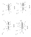
- FIG. 1 internal fixation in the spine is often accomplished by first screwing fixation screws 200 into the pedicles and vertebral bodies of the vertebrae 88.
- Figure 2 shows that the fixation screws 200 are then typically attached to a rigid fixation rod or plate 94 that provides support between one or more weakened vertebra 88. This support often immobilizes the vertebra 88 to which the fixation screws 200 have been inserted.
- Figure 3 illustrates that existing fixation systems often have the fixation rod or plate 94 , through which a number of fixation screws 200 are deployed.
- the screw head 202 prevents the fixation rod 88 from separating from the fixation screw 200 .
- the fixation screw 200 also has a screw body 204 which has a screw longitudinal axis 206 often static relative to the fixation rod 94 .
- Figure 4 illustrates that in some existing fixation systems, the fixation screws 200 can be polyaxial screws: attached to the fixation rod or plate 94 in a manner so that the screw longitudinal axis 206 can rotate, as shown by arrows, with respect to the fixation rod 94 .
- the bones are often weak and under heavy loads, the bones can fail and the fixation screws can be ripped from the bone resulting in complete failure and additional damage to the bone.
- fixation screw that can substantially eliminate the risk of backout, and can provide a higher anchoring force is desired.
- a fixation screw that can also minimize bone failure is desired.
- Document WO 01/54598 discloses an implant adapted to anchor in cancellus bone, comprising a shaft defining an inflation lumen therethrough and at least one inflatable anchor portion connected to said lumen, whereby inflation of said anchor portion causes said implant to engage the cancellus bone.
- document WO 2006/116760 discloses an expandable support device that can be screwed into a damaged tissue site and then expands within the damaged tissue site.
- document US 2002/0049447 discloses a surgical fixation device for fixation in a biological medium, wherein the device comprises an outer, threaded member having an internal longitudinal bore in which a shaft member is slidably received, said shaft member having a cam surface for transforming axial displacement of the shaft member into radial expansion of the threaded outer member. Axial displacement of said inner shaft member can be effected by means of a rotatable tool.
- the present invention provides for an attachment device for biological implantation as described in claim 1.
- the devices described herein can be used as substitutes for fixation screws in existing fixation systems.
- the devices can be used to treat broken bones, scoliosis, kyphosis, spondylothisthesis and rotation, segmental instability, such as disc degeneration and fracture caused by disease and trauma and congenital defects, and degeneration caused by tumors.
- Figure 5 illustrates that the expandable attachment device 2 can have an unexpandable section 4 at a proximal end, an expandable section 6 at a medial length along the expandable attachment device 2 , and a distal end 8 .
- the unexpandable section 4 can be distal to the expandable section 6
- the expandable attachment device 2 can have more than one expandable section 6 and/or unexpandable section 4 that can be interspersed with each other.
- the expandable attachment device 2 can have an expandable attachment device axis 10 .
- the expandable device axis can be substantially straight.
- the proximal end of the expandable attachment device 2 can have a tip 12.
- the tip 12 can be sharpened or otherwise configured to seat the expandable attachment device 2 in bone (e.g., having cutting teeth).
- the unexpandable section 4 can have unexpandable thread 14, for example, configured to screw the expandable attachment device 2 into bone.
- Figure 5 shows that the expandable attachment device 2 can have a radially contracted configuration.
- Figure 6 illustrates that the expandable attachment device 2 can have a radially expanded configuration.
- the expandable section 6 can be radially expanded, as shown by arrows.
- the expandable section 6 can be resiliently and/or deformably expandable.
- the expandable sections 6 can be radially expanded by axial compression (e.g., see Figs. 8-11 ), rotation (e.g., see Figs. 26-29 ), use of a lever such as a wedge, ramp or jack (e.g., see Figs. 58-64), or combinations thereof.
- the expandable attachment device 2 can be substantially flat or planar.
- the expandable section 6 can be biased to resiliently radially expand.
- the expandable section 6 can be self-expandable or releasable spring.
- the expandable section 6 can be resiliently radially expandable and can be additionally deformably radially expandable to a larger radius than achieved by resilient expansion alone.
- the expandable section 6 can have one or more anchors extending radially therefrom when the expandable section 6 is in the radially expanded configuration.
- the anchors can be brads, hooks, pins, teeth, fasteners, pegs, screws, skewers, spikes, stakes, or combinations thereof.
- the expandable attachment device 2 can be configured to radially expand in volumetrically, for example to have radial expansion in two dimensions.
- the expandable attachment device 2 can be configured to radially expand planarly, for example, in a single dimension (i.e., to have radial expansion in only two substantially opposite directions).
- Figure 7 illustrates that the expandable attachment device axis 10 can be substantially curved or angled.
- the expandable attachment device axis 10 can have one or more curved, ad/or angled, and/or straight lengths.
- the expandable attachment device axis 10 can have a substantially straight length along the unexpandable section 4 and the distal end 8 , and a curved length along the expandable section 6 .
- the expandable attachment device axis 10 can have one or more curves with a constant or variable (i.e., changing along the length of the attachment device axis 10 ) radius of curvature and/or one or more abrupt and discrete non-zero angles.
- the expandable attachment device 2 When the expandable attachment device 2 is inserted in a bone, such as a vertebra, the expandable attachment device 2 can follow a longitudinal axis of insertion that is straight, curved, or a combination thereof.
- the expandable attachment device 2 can follow a longitudinal axis of insertion through the bone that is substantially similar in shape to the expandable attachment device axis 10 .
- Figures 8 and 9 illustrates that the expandable attachment device 2 can be radially expanded by applying a proximally-directed force to the distal end 8 as shown by arrows of Figure 8 .
- the proximally-directed force can be substantially parallel to the expandable attachment device axis 10 .
- the proximal force can be opposed by a distal force applied, for example, by the bone and/or a deployment tool 16 .
- the expandable section 6 can then radially expand, as shown by arrows in Figure 9 .
- Figures 10 and 11 illustrate that the expandable attachment device 2 can have expandable thread 18 on the expandable section 6 and unexpandable thread 14 on the unexpandable section 4 .
- the expandable thread 18 can radially expand with the remainder of the expandable section 14 .
- the expandable attachment device 2 shown in Figures 10 and 11 can be radially expanded by the method as shown in Figures 8 and 9 .
- Figures 12 and 13 illustrate that the expandable attachment device 2 can be radially expanded by applying a distally-directed force to the distal end 8 as shown by arrow.
- the distally-directed force can be substantially parallel to the expandable attachment device axis 10 .
- the distal force can be opposed by a proximal force applied, for example, by the bone and/or a deployment tool 16 .
- the expandable section 6 can then radially expand, as shown by arrows in Figure 13 .
- Figures 14 and 15 illustrate that the expandable attachment device 2 can have expandable thread 18 on the expandable section 6 and unexpandable thread 14 on the unexpandable section 4 .
- the expandable thread 18 can radially expand with the remainder of the expandable section 6 .
- the expandable attachment device 2 shown in Figures 14 and 15 can be radially expanded by the method as shown in Figures 12 and 13 .
- Figures 16 illustrate that substantially the entire length of the expandable attachment device 2 can be the expandable section 6.
- the distal end can extend distally from the expandable section 6 .
- Figure 17 illustrates that the entire expandable section 6 can radially expand.
- Figures 16 and 17 illustrate that the expandable section 6 can have expandable thread 18 .
- Figures 18 and 19 illustrate the variation of the expandable attachment device 2 of Figures 16 and 17 , respectively, without expandable thread 18 .
- Figure 20 illustrates that the expandable attachment device 2 can have, from distal to proximal, a first expandable section 20, a third expandable section 24, and a second expandable section 22.
- the first, second and third expandable sections 20 , 22 , 24 can radially expand at different rates (e.g., under different deployment loads, for example one or more are resiliently and one or more are deformably expandable).
- the first and second expandable sections 20, 22 can radially expand at the same rate
- the third expandable section 24 can radially expand at a lesser rate.
- Figure 21 illustrates that the expandable section 6 can have a number of struts 26 attached to each other at joints 28.
- the struts 26 can be configured to form diamond-shaped ports 30 .
- the expandable section 6 can have a distal hoop 32 at the distal end 8 and/or a proximal hoop 34 at the proximal end.
- the hoops can attach to all of the struts 26 at the respective end.
- the hoops and struts 26 can all be integral with and/or attached to each other.
- Figure 22 illustrates that longitudinal compressive force, shown by arrow 36 , can be applied to the expandable section 6 , for example resulting in radial expansion, shown by arrows 38 .
- the struts 26 can deform near the joints 28 .
- the hoops can remain substantially static.
- Figures 23 and 24 illustrates that the expandable section 6 can be radially expanded by longitudinally compressing the expandable section 6 .
- the deployment tool 16 ( or expandable attachment device 2 ) can have an anvil 40 and a deployment cap 42 .
- the anvil 40 can be the distal end 8 and/or the unexpandable section 14 .
- the deployment cap 42 can be the unexpandable section 14 and/or the distal end 8 , for example, the opposite of the anvil 40.
- the expandable section can be compressed between the anvil 40 and the deployment cap 42.
- the deployment tool 16 (or expandable attachment device 2) can have a deployment rod 44, for example to transmit the compressive force to the deployment cap 42.
- the deployment rod 44 can be releasably attached to the deployment cap 42, for example via a releasable deployment anchor 46.
- the releasable deployment anchor 46 can be released and the deployment rod 44 can be removed after the expandable section 6 is radially expanded.
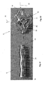
- Figure 25 illustrates that the expandable attachment device 2 can have a fixation joint 48.
- the fixation joint 48 can be fixedly or removably attached to the expandable attachment device 2 , for example interference fit with the distal end 8.
- the fixation joint 48 can be uniaxially or polyaxially rotatably (e.g., with one, two or three degrees or rotational freedom) and/or translatably attached to the expandable support device 2 .
- the fixation joint 48 can be configured to attach to a fixation element, such as a rod or plate configured to substantially fix the bone into which the expandable attachment device 2 is inserted.
- the cells 50 can be W-shaped, A-shaped, V-shaped, another configuration disclosed herein for cells 50 , or combinations thereof.
- a single expandable section can have various cell 50 configurations.
- a scale 51 is shown numbered in millimeters.
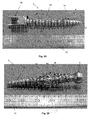
- Figure 26 illustrates that the struts 26 can be in a radially expanded configuration.
- the cells can be in an opened configuration.
- the expander can be configured to be a radially non-expandable center shaft or radially expandable.
- the expandable attachment device 2 can be radially expanded, for example, by compressing the expander 52 and/or by longitudinally compressing the expandable attachment device 2 .
- the longitudinally distal end 8 can be removably or fixedly attached to a cap.
- the cap can be configured to attach to the fixation joint 48.
- a scale 51 is shown numbered in millimeters.
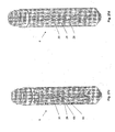
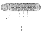
- Figures 27a-e illustrate variations of the strut 26 , port 30 and joint 28 configuration of the expandable section.
- Figure 27a illustrates that the ports 30 can be larger near the longitudinal median or a central section 31a of the expandable section 6 .
- the lengths of the expandable section 6 with larger ports 30 can radially expand during longitudinal compression 54 before the lengths of the expandable section 6 with smaller ports 30 , for example along the end regions 31b .
- the expandable attachment device 2 can have an engagement configuration, such as thread 33, that can be configured to removably attach to a deployment tool.
- the engagement configuration can be at or near the proximal end of the expandable support device 2 .
- the engagement configuration can have a tool port 35 .
- the tool port 35 can be configured to engage a deployment tool, for example a hex key or Allen wrench.
- the tool port 35 can be an open port.
- the tool port 35 can provide access through the proximal end of the expandable support device into the central channel 37 of the expandable support device.
- filler can be deployed through the tool port 35 and into the central channel 37 . Filler can then exit from the central channel 37 through the cells or side ports 30 and, for example, into the cancellous bone surrounding the device 2 .
- Figure 27b illustrates that the struts 26 and ports 30 can be substantially identical along the entire length of the expandable section 6 .
- Figure 27c can have main struts 68 and smaller folded cross-struts 80 that attach to multiple main struts 68.
- Figure 27d illustrates that the struts 26 and ports 30 can be substantially identical along the entire length of the expandable section 6 and that the ports 30 can be longer in the longitudinal direction that in the angular direction, with respect to the expandable section 6.
- Figure 27e that the struts 26 and ports 30 can be substantially identical along the entire length of the expandable section 6 and that the ports 30 can be longer in the longitudinal direction that in the angular direction, with respect to the expandable section 6 , and smaller and more numerous than as shown in Figure 27d .
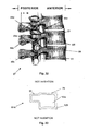
- Figure 28 illustrates that the expandable attachment device 2 can be releasably attached to the deployment tool 16 .
- the deployment tool 16 can have deployment engagement teeth 56 that can align and intersect with the distal end cap 58 , for example at the cap deployment tool attachments 60.
- Figure 29 illustrates that the deployment tool 16 can have a first tool handle 62 , a second tool handle 64 , a third tool handle 66 , or combinations thereof
- the tool handles 62 , 64 , 66 can be independently or jointly attached to, and configured to control, one or more tools within, attached or attachable to the deployment tool 16 , such as a mechanical driver (e.g., screw driver 70 , expander driver 72 , holder, or combinations thereof) or a valve or power control for controlling the flow of a filler material or saline, or for operating a visualization or electrocautery or RF device.
- the tool handles can be configured to provide mechanical stability for the deployment tool 16 .
- the tool handles can be configured to ratchet (i.e., unidirectional movement or substantially free unidirectional motion with safety-controlled bi-directional motion).
- the tool handles can be configured to control rotation and translation or screwing of the expandable attachment device 2 into the target site.
- the tool handles can be configured to control the expandable attachment device 2 attachment to and release from the deployment tool 16.
- the tool handles can be configured to control the radial expansion 38 of the expandable attachment device 2.
- the tool handles can be longitudinally translatable and/or rotatable.
- the tool handles can be configured for ergonomic use.
- the third tool handle 66 can have a knurled surface.
- the second tool handle 64 can have wings, for example configured as finger or thumb controls.
- the first tool handle 62 can have a configuration that is conical, cylindrical or combinations thereof.
- the deployment tool 16 can have a tool shaft 74.
- the expandable attachment device 2 can be releasably attached to the tool shaft 74 .
- Figure 30a illustrates that the tool shaft 74 can have an expander driver 72 and a screw driver 70.
- the terminal end of the tool shaft 74 can be aligned with the distal end 8 of the expandable attachment device 2 .
- Figure 30b illustrates that the terminal end of the tool shaft 74 can be placed, as shown by arrow, in contact with the expandable attachment device 2.
- the screw driver 70 e.g., the distal end of the deployment tool attachment
- the expander driver 72 can releasably attach to or engage the expander head (e.g., the expander deployment tool attachment).
- the deployment tool 16 can screw the expandable attachment device 2 into a target tissue site (e.g., a bone, such as vertebral body 76 ) .
- Figure 30c illustrates that the expander driver 72 can deploy a longitudinal compressive force, shown by arrow 36 , to the expander 52 .
- the surrounding tissue can resist the longitudinal compressive force, as shown by in vivo resisting force arrow 78 .
- the expander 52 fingers can radially expand, as shown by arrows 38 .
- the expander 52 fingers can force the expandable section 6 (e.g., the struts 26 ) radially outward, as shown by arrows.
- the expandable attachment device 2 can be deformably or resiliently radially expanded.
- Figure 30d illustrates that the tool shaft 74 can be detached or disengaged and withdrawn from the expandable attachment device 2 and the target site.
- Figure 31a illustrates that the tool shaft 74 can have a holder shaft 82 terminating in one or more holder grips 86 .
- the holder grips 86 can be rotatably attached to the holder shaft 82 at holder hinges. When the tool shaft 74 is aligned with and adjacent to the expandable attachment device 2, the holder grips 86 can be flexed or rotated radially outward.
- the holder grips 86 can be configured to attach to the distal end 8 of the expandable attachment device 2 .
- Figure 31b illustrates that the terminal end of the tool shaft 74 can be placed, as shown by arrow, in contact with the expandable attachment device 2 .
- the holder grips 86 can be flexed or rotated radially inward.
- the holder grips 86 can attach to the distal end 8 of the expandable attachment device 2 .
- Figure 31c illustrates that the expander driver 72 can deploy a longitudinal compressive force 36 , shown by arrow, to the expander 52 .
- the surrounding tissue can resist the longitudinal compressive force 36 , as shown by in vivo resisting force arrow 78 , and/or the holder shaft 82 and holder grips 86 can pull, as shown by arrows 84 , on the distal end 8 producing an external resisting force to oppose the longitudinal compressive force, as shown by arrow 36 .
- the expander 52 fingers can radially expand, as shown by arrows 38 .
- the expander 52 fingers can force the expandable section 6 (e.g., the struts 26 ) radially outward, as shown by arrows.
- the expandable attachment device 2 can be deformably or resiliently radially expanded.
- Figure 31d illustrates that the holder grips 86 can flex or rotate radially outward, as shown by arrows.
- the holder grips 86 can detach or disengage from the distal end 8 of the expandable attachment device 2.
- the tool shaft 74 can be withdrawn from the expandable attachment device 2 and the target site.
- the expandable attachment device 2 can be removed by reversing the deployment method.
- the expander 52 and/or screw can be longitudinally pulled and expanded resulting in radial contraction of the expandable attachment device 2 (e.g., the struts 26 ).
- the expandable attachment device 2 can then be unscrewed or otherwise removed from the target site.
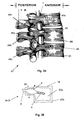
- Figure 32 illustrates a side view of a spine 87 .
- Vertebrae 88 within the spine 87 can have known anatomical features such as transverse processes 88a , spinous processes 88b , interior articular facets 88c , superior articular processes 88d , intervertebral foramen 88e , and vertebral bodies 88f .
- the spine 87 can also have intervertebral discs 89 and a spinal cord 9 1 .
- Figure 33 illustrates that harder, cortical bone 92b surrounds softer, cancellous bone 92a in the vertebra 88.
- Figure 34 illustrates that the expandable attachment device 2 can be translated and/or rotated into the pedicle 90 and/or into the vertebral body 76.
- the expanded section 6 can be positioned in the cortical bone 92b.
- Figures 35 and 36 illustrate that the expandable section 6 can be radially expanded, for example in the cancellous bone 92a of the pedicle 90 and/or the vertebral body 76.
- the radius of the radially expanded section 6 can be larger than the entry hole created to insert the attachment device 2 into the vertebra 88.
- the distal end 8 can extend from the bone.
- a separate device such as a fixation rod 94 or plate, can be attached to the distal end 8.
- Figure 37 illustrates that the expandable attachment device 2 can be aligned with or adjacent to the pedicle 90 of the vertebral arch.
- Figure 38 illustrates that the expandable attachment device 2 can be screwed or otherwise inserted, as shown by arrow 47 , into the vertebral body 76 through cortical bone 92b and cancellous bone 92a .
- the tip 12 can pierce the bone.
- the expandable thread 18 and unexpandable thread 14 can screw through the bone and anchor in the bone.
- the fixation joint 48 can rotate, as shown by arrow 45 , relative to the remainder of the expandable attachment device 2.
- Figure 39 illustrates that the expandable attachment device 2 and/or the expander 52 can be longitudinally compressed, as shown by arrow 54 .
- the longitudinal compression of the expandable attachment device 2 and/or the expander 52 can radially expand, as shown by arrows 38 , the expandable section 6 .
- the expandable section 6 can be configured to expand through the cancellous bone 92a and confirm to the cortical bone 92b during radial expansion.
- Figure 40 illustrates that a filler 49, such as materials disclosed herein, can be deployed, as shown by arrows, through or adjacent to the expandable attachment device 2, for example through the open cells 50.
- the filler 49 can be a liquid, gel, small solid particles (e.g., morselized bone), or combinations thereof.
- Figure 41 illustrates that the fixation joint 48 can substantially partially minimize the transmission of excessive forces to the bone from the expandable attachment device 2 from.
- the fixation joint 48 can rotate, as shown by arrow 77 , about one or more axes.
- the fixation joint 48 can absorb, as shown by arrow 79, mechanical loads, for example by flexing, deforming, bending, and/or translating relatively small distances.
- Figure 42 illustrates that the expandable attachment device 2 can be screwed through cortical bone 92b and into the cancellous bone 92a of a vertebral body 76 .
- Figure 43 illustrates that a longitudinal force can be applied by the deployment tool 16 .
- the expandable section 6 can partially radially expand, as shown by arrows.
- the radial expansion 38 of the expandable section 6 can be directionally unequal, for example, conforming to the cortical bone 92b of the vertebra 88 .
- the unexpandable section 4 of the expandable attachment device 2 can remain substantially stationary, for example, due to normal resistive forces from the surrounding tissue in vivo, and/or due to external resistive forces 84 deployed by the deployment tool 16 , for example on the distal end 8 of the expandable attachment device 2 (e.g., as shown in Figure 31 c) ,
- Figures 44 and 45 illustrate additional application of longitudinal force, as shown by arrow 36 , by the deployment tool 16.
- the expandable section 6 can more fully radially expand, as shown by arrows 38 , compared to the partial radial expansion shown in Figure 43 .
- the expandable section 6 can further radially expand to conform to the inner surface of the cortical bone 92b .
- Figure 46 illustrates that a non-expandable screw 98 and an expandable attachment device 2 can be inserted into the same vertebral body 76 .
- Figure 47 illustrates that the non-expandable screw 98 can be forcibly withdrawn, as shown by arrow 100 , from the vertebral body 76 by a screw translational withdrawal force.
- the minimum screw translational withdrawal force needed to remove the non-expandable screw 98 from the vertebral body 76 without rotating the non-expandable screw 98 can be, for example, about 400 N (90 lbs.).
- Figure 48 illustrates that the expandable attachment device 2 can be forcibly withdrawn, as shown by arrow 102 , from the vertebral body 76 by an expandable attachment device translational withdrawal force 102 .
- the minimum expandable attachment device translational withdrawal force 102 needed to remove the expandable attachment device 2 from the vertebral body 76 without rotating or radially contracting the non-expandable screw 98 can be, for example, about 556 N (125 lbs.).
- Figure 49 illustrates that the after use (e.g., a high expandable attachment device translational withdrawal force applied) the cortical bone 92b surrounding the deployed expandable attachment device 2 can be substantially unaffected.
- the struts 26 can distribute withdrawal forces across a large area of cancellous and cortical bone 92a and 92b , for example reducing pressure compared with a comparable non-expandable screw 98.
- Figure 50 illustrates that a second expandable attachment device 2b can be deployed inside of a first expandable attachment device 2a .
- the second unexpandable section 22 and, optionally, the second expandable section 22 can be longitudinally placed inside the expanded or unexpanded first expandable section 20 .
- the first expandable section 20 can be expanded before of after the introduction of the second expandable attachment device 2b in the first expandable section 20.
- the first expandable section 20 can be radially expanded by the expansion of the second expandable section 22.
- the cells on the first expandable attachment device 2a can be obstructed (i.e., be out of phase or out of sequence) by the struts 26 of the second expandable attachment device 2b , and/or the cells 50 on the first expandable attachment device 2b can be open and align (i.e., be in phase or in sequence) with the cells 50 of the second expandable attachment device 2b .
- Filler can be introduced into the second expandable attachment device 2b and deployed through the cells 50 of the first and second expandable attachment devices 2b into the target site.
- any or all elements of the expandable attachment device 2 and/or other devices or apparatuses described herein can be made from, for example, a single or multiple stainless steel alloys, nickel titanium alloys (e.g., Nitinol), cobalt-chrome alloys (e.g., ELGILOY® from Elgin Specialty Metals, Elgin, IL; CONICHROME® from Carpenter Metals Corp., Wyomissing, PA), nickel-cobalt alloys (e.g., MP35N® from Magellan Industrial Trading Company, Inc., Westport, CT), molybdenum alloys (e.g., molybdenum TZM alloy, for example as disclosed in International Pub. No.
- nickel titanium alloys e.g., Nitinol
- cobalt-chrome alloys e.g., ELGILOY® from Elgin Specialty Metals, Elgin, IL; CONICHROME® from Carpenter Metals Corp., Wyomissing, PA
- WO 03/082363 A2 published 9 October 2003 , which is herein incorporated by reference in its entirety
- tungsten-rhenium alloys for example, as disclosed in International Pub. No. WO 03/082363
- polymers such as polyethylene teraphathalate (PET), polyester (e.g., DACRON® from E. I.
- poly ester amide polypropylene
- aromatic polyesters such as liquid crystal polymers (e.g., Vectran, from Kuraray Co., Ltd., Tokyo, Japan), ultra high molecular weight polyethylene (i.e., extended chain, high-modulus or high-performance polyethylene) fiber and/or yarn (e.g., SPECTRA® Fiber and SPECTRA® Guard, from Honeywell International, Inc., Morris Township, NJ, or DYNEEMA® from Royal DSM N.V., Heerlen, the Netherlands), polytetrafluoroethylene (PTFE), expanded PTFE (ePTFE), polyether ketone (PEK), polyether ether ketone (PEEK), poly ether ketone ketone (PEKK) (also poly aryl ether ketone ketone), nylon, polyetherblock co-polyamide polymers (e.g., PEBAX® from ATOFINA, Paris, France), aliphatic polymers (e.g., PEBAX® from ATOFINA
- any or all elements of the expandable attachment device 2 and/or other devices or apparatuses described herein can be, have, and/or be completely or partially coated with agents for cell ingrowth.
- the expandable attachment device 2 and/or elements of the expandable attachment device 2 and/or other devices or apparatuses described herein can be filled, coated, layered and/or otherwise made with and/or from cements, fillers, and/or glues known to one having ordinary skill in the art and/or a therapeutic and/or diagnostic agent. Any of these cements and/or fillers and/or glues can be osteogenic and osteoinductive growth factors.
- cements and/or fillers examples include bone chips, demineralized bone matrix (DBM), calcium sulfate, coralline hydroxyapatite, biocoral, tricalcium phosphate, calcium phosphate, polymethyl methacrylate (PMMA), biodegradable ceramics, bioactive glasses, hyaluronic acid, lactoferrin, bone morphogenic proteins (BMPs) such as recombinant human bone morphogenetic proteins (rhBMPs), other materials described herein, or combinations thereof.
- DBM demineralized bone matrix
- PMMA polymethyl methacrylate
- BMPs bone morphogenic proteins
- rhBMPs recombinant human bone morphogenetic proteins
- the agents within these matrices can include any agent disclosed herein or combinations thereof, including radioactive materials; radiopaque materials; cytogenic agents; cytotoxic agents; cytostatic agents; thrombogenic agents, for example polyurethane, cellulose acetate polymer mixed with bismuth trioxide, and ethylene vinyl alcohol; lubricious, hydrophilic materials; phosphor cholene; anti-inflammatory agents, for example non-steroidal anti-inflammatories (NSAIDs) such as cyclooxygenase-1 (COX-1) inhibitors (e.g., acetylsalicylic acid, for example ASPIRIN® from Bayer AG, Leverkusen, Germany; ibuprofen, for example ADVIL® from Wyeth, Collegeville, PA; indomethacin; mefenamic acid), COX-2 inhibitors (e.g., VIOXX® from Merck & Co., Inc., Whitehouse Station, NJ; CELEBREX® from Pharmacia Corp
- fractures types that can be treated with the disclosed device include Greenstick fractures, transverse fractures, fractures across growth plates, simple fractures, wedge fractures, complex fractures, compound fractures, complete fractures, incomplete fractures, linear fractures, spiral fractures, transverse fractures, oblique fractures, comminuted fractures, impacted fractures, and soft tissue tears, separations (e.g., avulsion fracture), sprains, and combinations thereof.
- Plastic deformations of bones can also be treated with the disclosed device.
- fingers e.g., phalanges
- hands e.g., metacarpals, carpus
- toes e.g., tarsals
- feet metalatarsals, tarsus
- legs e.g., femur, tibia, fibula
- arms e.g., humerus, radius, ulna
- scapula
- All dimensions shown herein are exemplary.
- the dimensions shown herein can at least be expanded to ranges from about 50% to about 150% of the exemplary dimension shown herein, more narrowly from about 75% to about 125% of the exemplary dimension shown herein.
- radial expansion refers to both a volumetric increase of an element, or an increase in the radial dimension of the element itself, or the increase in the maximum radius of the element as measured from the expandable attachment device axis 10.
- Any elements described herein as singular can be pluralized (i.e., anything described as "one” can be more than one).
- Any species element of a genus element can have the characteristics or elements of any other species element of that genus.
- the above-described configurations, elements or complete assemblies and methods and their elements for carrying out the invention, and variations of aspects of the invention can be combined and modified with each other in any combination.
Claims (7)
- Dispositif de fixation pour implantation biologique, doté d'un axe longitudinal (10) et d'une longueur longitudinale, comprenant :une vis présentant une section extensible radialement (6 ; 20, 22, 24) et une section non extensible radialement (4), la section extensible radialement présentant un rayon extensible radialement ; etun élément d'extension (52) reçu coulissant par la vis, l'élément d'extension (52) comprenant une tête d'extension,l'élément d'extension comprenant un premier doigt d'extension s'étendant longitudinalement depuis la tête d'extension, et un second doigt d'extension s'étendant longitudinalement depuis la tête d'extension, la vis comprenant des filets s'étendant radialement (14, 18), et l'élément d'extension (52) comprenant des filets s'étendant radialement,caractérisé en ce que la vis comporte une première cellule (50) et une seconde cellule (50), et en ce que la première cellule (50) est décalée longitudinalement par rapport à la seconde cellule (50).
- Dispositif selon la revendication 1, dans lequel le rayon extensible radialement est configuré pour s'agrandir radialement quand la longueur longitudinale est contractée longitudinalement.
- Dispositif selon la revendication 1, comprenant en outre un joint de fixation (48) fixé rotatif à la vis, dans lequel le joint de fixation est configuré pour se fixer à un dispositif séparé.
- Dispositif selon la revendication 3, dans lequel le joint de fixation (48) est fixé rotatif à la vis avec plus d'un degré de liberté en rotation.
- Dispositif selon la revendication 1, dans lequel la section extensible radialement (6) comprend deux entretoises (26).
- Dispositif selon la revendication 1, dans lequel au moins une partie de l'axe longitudinal (10) comprend une configuration essentiellement incurvée.
- Dispositif selon la revendication 1, dans lequel l'élément d'extension (52) est essentiellement plan.
Priority Applications (1)
| Application Number | Priority Date | Filing Date | Title |
|---|---|---|---|
| EP15177513.7A EP2974672B1 (fr) | 2007-11-02 | 2008-10-31 | Dispositif de fixation expansible |
Applications Claiming Priority (2)
| Application Number | Priority Date | Filing Date | Title |
|---|---|---|---|
| US98508707P | 2007-11-02 | 2007-11-02 | |
| PCT/US2008/082118 WO2009059227A1 (fr) | 2007-11-02 | 2008-10-31 | Dispositif de fixation extensible et procédé |
Related Child Applications (2)
| Application Number | Title | Priority Date | Filing Date |
|---|---|---|---|
| EP15177513.7A Division-Into EP2974672B1 (fr) | 2007-11-02 | 2008-10-31 | Dispositif de fixation expansible |
| EP15177513.7A Division EP2974672B1 (fr) | 2007-11-02 | 2008-10-31 | Dispositif de fixation expansible |
Publications (3)
| Publication Number | Publication Date |
|---|---|
| EP2205162A1 EP2205162A1 (fr) | 2010-07-14 |
| EP2205162A4 EP2205162A4 (fr) | 2012-01-04 |
| EP2205162B1 true EP2205162B1 (fr) | 2015-09-09 |
Family
ID=40591501
Family Applications (2)
| Application Number | Title | Priority Date | Filing Date |
|---|---|---|---|
| EP15177513.7A Active EP2974672B1 (fr) | 2007-11-02 | 2008-10-31 | Dispositif de fixation expansible |
| EP08843886.6A Active EP2205162B1 (fr) | 2007-11-02 | 2008-10-31 | Dispositif de fixation extensible |
Family Applications Before (1)
| Application Number | Title | Priority Date | Filing Date |
|---|---|---|---|
| EP15177513.7A Active EP2974672B1 (fr) | 2007-11-02 | 2008-10-31 | Dispositif de fixation expansible |
Country Status (4)
| Country | Link |
|---|---|
| US (1) | US8636784B2 (fr) |
| EP (2) | EP2974672B1 (fr) |
| JP (3) | JP2011502584A (fr) |
| WO (1) | WO2009059227A1 (fr) |
Cited By (1)
| Publication number | Priority date | Publication date | Assignee | Title |
|---|---|---|---|---|
| DE102020131376A1 (de) | 2020-11-26 | 2022-06-02 | Universität Leipzig | Implantatschraube |
Families Citing this family (45)
| Publication number | Priority date | Publication date | Assignee | Title |
|---|---|---|---|---|
| US20080288003A1 (en) * | 2006-11-06 | 2008-11-20 | Mckinley Laurence M | Reversibly expandable fixation device |
| WO2008112308A1 (fr) * | 2007-03-12 | 2008-09-18 | Stout Medical Group, L.P. | Dispositif de fixation gonflable et procédé associé |
| US8556949B2 (en) * | 2007-11-14 | 2013-10-15 | DePuy Synthes Products, LLC | Hybrid bone fixation element and methods of using the same |
| US20090138043A1 (en) * | 2007-11-28 | 2009-05-28 | Medtronic Spine Llc | Threaded access cannula and methods of using the same |
| CN102626338B (zh) | 2008-01-14 | 2014-11-26 | 康文图斯整形外科公司 | 用于骨折修补的装置和方法 |
| CA2728312A1 (fr) * | 2008-06-19 | 2009-12-23 | Synthes Usa, Llc | Techniques, systemes et implants permettant d'augmenter la prise d'une vis a os |
| US20100228301A1 (en) * | 2009-03-09 | 2010-09-09 | Greenhalgh E Skott | Attachment device and methods of use |
| US8734497B2 (en) | 2009-03-13 | 2014-05-27 | The University Of Toledo | Removable anchoring pedicle screw |
| CA2760749A1 (fr) | 2009-05-08 | 2010-11-11 | Synthes Usa, Llc | Implant d'os extensible |
| WO2011088172A1 (fr) | 2010-01-15 | 2011-07-21 | Brenzel Michael P | Tige orthopédique tournante rigide |
| WO2011091052A1 (fr) | 2010-01-20 | 2011-07-28 | Kyle Taylor | Appareil et procédés pour accès à un os et préparation d'une cavité |
| US20120029578A1 (en) * | 2010-02-05 | 2012-02-02 | Sean Suh | Bio-Resorbable Capsule Containing Fenestrated Screw System For Osteoporotic Subject |
| US8906022B2 (en) * | 2010-03-08 | 2014-12-09 | Conventus Orthopaedics, Inc. | Apparatus and methods for securing a bone implant |
| US9498273B2 (en) | 2010-06-02 | 2016-11-22 | Wright Medical Technology, Inc. | Orthopedic implant kit |
| US9724140B2 (en) | 2010-06-02 | 2017-08-08 | Wright Medical Technology, Inc. | Tapered, cylindrical cruciform hammer toe implant and method |
| US8608785B2 (en) | 2010-06-02 | 2013-12-17 | Wright Medical Technology, Inc. | Hammer toe implant with expansion portion for retrograde approach |
| EP2446842B1 (fr) * | 2010-10-26 | 2015-12-02 | Christian Röbling | Dispositif de stabilisation d'une colonne vertébrale |
| US9220535B2 (en) | 2010-10-26 | 2015-12-29 | Christian Röbling | Process for introducing a stabilizing element into a vertebral column |
| US20120123481A1 (en) * | 2010-11-15 | 2012-05-17 | Lin Chih I | Bone fixation device |
| US9161794B2 (en) * | 2011-04-14 | 2015-10-20 | Globus Medical, Inc. | Expanding spinal anchor |
| US9155578B2 (en) | 2012-02-28 | 2015-10-13 | DePuy Synthes Products, Inc. | Expandable fastener |
| EP2676622B1 (fr) | 2012-06-18 | 2015-12-30 | Biedermann Technologies GmbH & Co. KG | Ancrage osseux |
| EP2910210B1 (fr) | 2012-06-18 | 2018-03-07 | Biedermann Technologies GmbH & Co. KG | Ancrage osseux |
| WO2014055368A1 (fr) * | 2012-10-02 | 2014-04-10 | Alphatec Spine, Inc. | Vis expansible et procédés d'utilisation |
| TWI495458B (zh) * | 2012-11-13 | 2015-08-11 | Univ Chang Gung | A device that supports bone strength |
| EP2740428B1 (fr) | 2012-12-05 | 2019-05-08 | Biedermann Technologies GmbH & Co. KG | Élément d'ancrage osseux dynamique et procédé de fabrication d'un élément d'ancrage osseux dynamique |
| US20140180428A1 (en) * | 2012-12-21 | 2014-06-26 | Wright Medical Technology, Inc. | Percutaneous expanding hammertoe implant |
| US8945232B2 (en) | 2012-12-31 | 2015-02-03 | Wright Medical Technology, Inc. | Ball and socket implants for correction of hammer toes and claw toes |
| US9474561B2 (en) | 2013-11-19 | 2016-10-25 | Wright Medical Technology, Inc. | Two-wire technique for installing hammertoe implant |
| US10022132B2 (en) | 2013-12-12 | 2018-07-17 | Conventus Orthopaedics, Inc. | Tissue displacement tools and methods |
| US9498266B2 (en) | 2014-02-12 | 2016-11-22 | Wright Medical Technology, Inc. | Intramedullary implant, system, and method for inserting an implant into a bone |
| US9545274B2 (en) | 2014-02-12 | 2017-01-17 | Wright Medical Technology, Inc. | Intramedullary implant, system, and method for inserting an implant into a bone |
| US9566095B2 (en) * | 2014-05-01 | 2017-02-14 | Morgan Packard Lorio | Sacroiliac joint fastener, systems, and methods of using the same |
| US20160038201A1 (en) * | 2014-08-11 | 2016-02-11 | Wright Medical Technology, Inc. | Flexible screw and methods for syndesmosis repair |
| EP3193788A4 (fr) | 2014-09-18 | 2018-09-05 | Wright Medical Technology, Inc. | Implant pour orteil en marteau et instrument |
| CN105960211B (zh) | 2014-12-19 | 2019-01-11 | 瑞特医疗技术公司 | 用于趾间关节固定术的髓内锚定件 |
| US10265110B2 (en) | 2015-10-19 | 2019-04-23 | Alphatec Spine, Inc. | Pedicle screw with raised root |
| WO2017147140A1 (fr) * | 2016-02-22 | 2017-08-31 | Conventus Orthopaedics, Inc. | Appareil et procédés de réparation de colonne vertébrale et d'articulation sacro-iliaque |
| WO2019010252A2 (fr) | 2017-07-04 | 2019-01-10 | Conventus Orthopaedics, Inc. | Appareil et méthodes de traitement d'os |
| US11026669B2 (en) * | 2017-07-13 | 2021-06-08 | Medtronic Vascular, Inc. | Collapsible dilator |
| US10172656B1 (en) * | 2017-09-15 | 2019-01-08 | Alphatec Spine, Inc. | Surgical screw |
| US10888363B2 (en) * | 2017-12-06 | 2021-01-12 | Stout Medical Group, L.P. | Attachment device and method for use |
| NL2020071B1 (en) * | 2017-12-12 | 2019-06-21 | Umc Utrecht Holding Bv | Deformable body and combination of such deformable body and a surgical screw element. |
| CN108670394B (zh) * | 2018-06-14 | 2024-04-19 | 谢少鹏 | 一种骨扩张结构 |
| KR102309109B1 (ko) * | 2019-11-26 | 2021-10-05 | 충남대학교산학협력단 | 골 고정용 치밀골 나사 보강구조체 및 그를 포함하는 치밀골 나사모듈, 치밀골 나사모듈의 골 내 설치방법 |
Family Cites Families (80)
| Publication number | Priority date | Publication date | Assignee | Title |
|---|---|---|---|---|
| US1438648A (en) * | 1921-08-04 | 1922-12-12 | Benjamin F Jacobs | Set screw |
| GR81919B (fr) | 1983-06-20 | 1984-12-12 | Ethicon Inc | |
| US4738255A (en) * | 1986-04-07 | 1988-04-19 | Biotron Labs, Inc. | Suture anchor system |
| US4898156A (en) * | 1987-05-18 | 1990-02-06 | Mitek Surgical Products, Inc. | Suture anchor |
| DE3936703A1 (de) * | 1989-11-03 | 1991-05-08 | Lutz Biedermann | Knochenschraube |
| US5360431A (en) * | 1990-04-26 | 1994-11-01 | Cross Medical Products | Transpedicular screw system and method of use |
| US5065490A (en) * | 1990-05-31 | 1991-11-19 | Combustion Engineering, Inc. | Threaded insert for repairing a nuclear assembly |
| US5037422A (en) * | 1990-07-02 | 1991-08-06 | Acufex Microsurgical, Inc. | Bone anchor and method of anchoring a suture to a bone |
| US5236445A (en) * | 1990-07-02 | 1993-08-17 | American Cyanamid Company | Expandable bone anchor and method of anchoring a suture to a bone |
| US5480403A (en) * | 1991-03-22 | 1996-01-02 | United States Surgical Corporation | Suture anchoring device and method |
| US5207679A (en) * | 1991-09-26 | 1993-05-04 | Mitek Surgical Products, Inc. | Suture anchor and installation tool |
| US5649950A (en) * | 1992-01-22 | 1997-07-22 | C. R. Bard | System for the percutaneous transluminal front-end loading delivery and retrieval of a prosthetic occluder |
| US5261909A (en) * | 1992-02-18 | 1993-11-16 | Danek Medical, Inc. | Variable angle screw for spinal implant system |
| US5501695A (en) * | 1992-05-27 | 1996-03-26 | The Anspach Effort, Inc. | Fastener for attaching objects to bones |
| CA2094111C (fr) | 1992-06-15 | 1999-02-16 | Daniel R. Lee | Dispositif et methode de fixation des sutures |
| US5522844A (en) * | 1993-06-22 | 1996-06-04 | Johnson; Lanny L. | Suture anchor, suture anchor installation device and method for attaching a suture to a bone |
| US5824011A (en) * | 1993-06-23 | 1998-10-20 | Kevin R. Stone | Suture anchor assembly |
| US5411522A (en) * | 1993-08-25 | 1995-05-02 | Linvatec Corporation | Unitary anchor for soft tissue fixation |
| FR2718012A1 (fr) * | 1994-03-30 | 1995-10-06 | T2C Sarl | Ancrage intra osseux. |
| US5489210A (en) * | 1994-05-13 | 1996-02-06 | Hanosh; Frederick N. | Expanding dental implant and method for its use |
| US5472452A (en) * | 1994-08-30 | 1995-12-05 | Linvatec Corporation | Rectilinear anchor for soft tissue fixation |
| US5649963A (en) * | 1994-11-10 | 1997-07-22 | Innovasive Devices, Inc. | Suture anchor assembly and methods |
| US5643321A (en) * | 1994-11-10 | 1997-07-01 | Innovasive Devices | Suture anchor assembly and methods |
| US5882350A (en) * | 1995-04-13 | 1999-03-16 | Fastenetix, Llc | Polyaxial pedicle screw having a threaded and tapered compression locking mechanism |
| US5662654A (en) * | 1995-06-14 | 1997-09-02 | Incont, Inc. | Bone anchor, insertion tool and surgical kit employing same |
| DE19607517C1 (de) * | 1996-02-28 | 1997-04-10 | Lutz Biedermann | Knochenschraube |
| GR1003032B (el) * | 1996-07-10 | 1998-12-16 | Ενδομυελικος, ευκαμπτος μηχανισμος θεραπειας καταγματων με χρηση διαξονικης προεντασεως. | |
| US5849004A (en) * | 1996-07-17 | 1998-12-15 | Bramlet; Dale G. | Surgical anchor |
| DE19652608C1 (de) * | 1996-12-18 | 1998-08-27 | Eska Implants Gmbh & Co | Prophylaxe-Implantat gegen Frakturen osteoporotisch befallener Knochensegmente |
| US5709708A (en) * | 1997-01-31 | 1998-01-20 | Thal; Raymond | Captured-loop knotless suture anchor assembly |
| US20070282443A1 (en) * | 1997-03-07 | 2007-12-06 | Disc-O-Tech Medical Technologies Ltd. | Expandable element |
| WO2001054598A1 (fr) | 1998-03-06 | 2001-08-02 | Disc-O-Tech Medical Technologies, Ltd. | Implants osseux expansibles |
| US5935129A (en) * | 1997-03-07 | 1999-08-10 | Innovasive Devices, Inc. | Methods and apparatus for anchoring objects to bone |
| IL128261A0 (en) | 1999-01-27 | 1999-11-30 | Disc O Tech Medical Tech Ltd | Expandable element |
| US20060271061A1 (en) * | 2001-07-25 | 2006-11-30 | Disc-O-Tech, Ltd. | Deformable tools and implants |
| US5782866A (en) * | 1997-03-25 | 1998-07-21 | Ethicon, Inc. | System for anchoring tissue to bone |
| US6585770B1 (en) * | 1997-06-02 | 2003-07-01 | Sdgi Holdings, Inc. | Devices for supporting bony structures |
| US6146406A (en) * | 1998-02-12 | 2000-11-14 | Smith & Nephew, Inc. | Bone anchor |
| US6200330B1 (en) * | 1998-11-23 | 2001-03-13 | Theodore V. Benderev | Systems for securing sutures, grafts and soft tissue to bone and periosteum |
| US6224604B1 (en) * | 1999-07-30 | 2001-05-01 | Loubert Suddaby | Expandable orthopedic drill for vertebral interbody fusion techniques |
| US6231561B1 (en) * | 1999-09-20 | 2001-05-15 | Appriva Medical, Inc. | Method and apparatus for closing a body lumen |
| DE69925169T2 (de) * | 1999-11-11 | 2006-02-23 | Synthes Ag Chur, Chur | Radial aufweitbarer marknagel |
| US20020049447A1 (en) * | 2000-08-29 | 2002-04-25 | Li Medical Technologies, Inc. | Expandable surgical fastener and method |
| US6350126B1 (en) * | 2000-09-01 | 2002-02-26 | Ricardo Levisman | Bone implant |
| US6652561B1 (en) * | 2000-10-13 | 2003-11-25 | Opus Medical, Inc | Method and apparatus for attaching connective tissues to bone using a perforated suture anchoring device |
| US6648893B2 (en) * | 2000-10-27 | 2003-11-18 | Blackstone Medical, Inc. | Facet fixation devices |
| US6733506B1 (en) * | 2000-11-16 | 2004-05-11 | Ethicon, Inc. | Apparatus and method for attaching soft tissue to bone |
| DE10122828A1 (de) | 2001-05-11 | 2002-11-14 | Philips Corp Intellectual Pty | Verfahren zum Training oder zur Adaption eines Spracherkenners |
| NL1018438C1 (nl) | 2001-07-02 | 2003-01-08 | Baat Medical Engineering B V | In- en uitklapbaar gereedschap voor plaatsing in een ruggenwervel. |
| GB0128953D0 (en) | 2001-12-04 | 2002-01-23 | Univ Dundee | Fixing device |
| US6743463B2 (en) | 2002-03-28 | 2004-06-01 | Scimed Life Systems, Inc. | Method for spray-coating a medical device having a tubular wall such as a stent |
| US20040138707A1 (en) * | 2003-01-14 | 2004-07-15 | Greenhalgh E. Skott | Anchor removable from a substrate |
| US20060052788A1 (en) * | 2003-02-04 | 2006-03-09 | Thelen Sarah L | Expandable fixation devices for minimally invasive surgery |
| US6945975B2 (en) * | 2003-07-07 | 2005-09-20 | Aesculap, Inc. | Bone fixation assembly and method of securement |
| WO2005034764A1 (fr) | 2003-09-12 | 2005-04-21 | Nmt Medical, Inc. | Dispositif et procedes permettant d'eviter la formation de thrombi dans l'appendice auriculaire gauche |
| US20050177182A1 (en) | 2003-12-04 | 2005-08-11 | Van Der Burg Erik J. | System and method for delivering a left atrial appendage containment device |
| DE102004009429A1 (de) * | 2004-02-24 | 2005-09-22 | Biedermann Motech Gmbh | Knochenverankerungselement |
| US7507241B2 (en) * | 2004-04-05 | 2009-03-24 | Expanding Orthopedics Inc. | Expandable bone device |
| WO2006034396A2 (fr) | 2004-09-21 | 2006-03-30 | Stout Medical Group, L.P. | Ballonnet et procedes de fabrication et d'utilisation |
| WO2006034436A2 (fr) | 2004-09-21 | 2006-03-30 | Stout Medical Group, L.P. | Dispositif de support expansible et procede d'utilisation |
| WO2006068682A1 (fr) | 2004-09-24 | 2006-06-29 | Stout Medical Group, L.P. | Dispositif de support expansible et procede d'utilisation |
| EP1804733A4 (fr) | 2004-09-24 | 2010-01-20 | Stout Medical Group Lp | Dispositifs de support expansibles et leurs procedes d'utilisation |
| US8162985B2 (en) * | 2004-10-20 | 2012-04-24 | The Board Of Trustees Of The Leland Stanford Junior University | Systems and methods for posterior dynamic stabilization of the spine |
| US7316715B2 (en) * | 2005-02-18 | 2008-01-08 | Howmedica Osteonics Corp. | Polyaxial screw for acetabular cup |
| US8696707B2 (en) * | 2005-03-08 | 2014-04-15 | Zyga Technology, Inc. | Facet joint stabilization |
| US7731751B2 (en) | 2005-03-31 | 2010-06-08 | Life Spine, Inc. | Expandable spinal devices and method of insertion |
| WO2006116760A2 (fr) | 2005-04-27 | 2006-11-02 | Stout Medical Group, L.P. | Dispositif support extensible et son procede d'utilisation |
| US7246811B2 (en) * | 2005-04-27 | 2007-07-24 | K-2 Corporation | Snowboard binding engagement mechanism |
| JP5112295B2 (ja) | 2005-04-27 | 2013-01-09 | スタウト メディカル グループ,エル.ピー. | 拡張型支持具およびその使用方法 |
| JP2008540037A (ja) * | 2005-05-18 | 2008-11-20 | ソノマ・オーソペディック・プロダクツ・インコーポレイテッド | 低侵襲で作動可能な骨固定装置、システムおよび使用方法 |
| US20070032791A1 (en) | 2005-07-14 | 2007-02-08 | Greenhalgh E S | Expandable support device and method of use |
| US20070093899A1 (en) * | 2005-09-28 | 2007-04-26 | Christof Dutoit | Apparatus and methods for treating bone |
| EP1948072A2 (fr) | 2005-10-04 | 2008-07-30 | Stout Medical Group, L.P. | Dispositif a support deployable et procede d'utilisation |
| WO2007065137A2 (fr) | 2005-11-30 | 2007-06-07 | Stout Medical Group, L.P. | Ballonnet, et ses methodes de fabrication et d'utilisation |
| WO2007073488A2 (fr) * | 2005-12-19 | 2007-06-28 | Stout Medical Group, L.P | Dispositif de support extensible et procede d'utilisation |
| WO2007076374A2 (fr) | 2005-12-19 | 2007-07-05 | Stout Medical Group, L.P. | Dispositif de support dilatable et son procede d’utilisation |
| WO2007076377A2 (fr) | 2005-12-19 | 2007-07-05 | Stout Medical Group, L.P. | Dispositif de support dilatable |
| ES2313472T3 (es) * | 2006-02-23 | 2009-03-01 | Biedermann Motech Gmbh | Dispositivo de anclaje oseo. |
| US8343200B2 (en) * | 2006-03-13 | 2013-01-01 | The Johns Hopkins University | Orthopedic screw system |
| US20080288003A1 (en) * | 2006-11-06 | 2008-11-20 | Mckinley Laurence M | Reversibly expandable fixation device |
-
2008
- 2008-10-31 EP EP15177513.7A patent/EP2974672B1/fr active Active
- 2008-10-31 EP EP08843886.6A patent/EP2205162B1/fr active Active
- 2008-10-31 JP JP2010532301A patent/JP2011502584A/ja not_active Withdrawn
- 2008-10-31 WO PCT/US2008/082118 patent/WO2009059227A1/fr active Application Filing
- 2008-11-03 US US12/264,181 patent/US8636784B2/en active Active
-
2013
- 2013-09-03 JP JP2013181781A patent/JP5755297B2/ja active Active
-
2015
- 2015-05-26 JP JP2015106133A patent/JP6195868B2/ja active Active
Cited By (1)
| Publication number | Priority date | Publication date | Assignee | Title |
|---|---|---|---|---|
| DE102020131376A1 (de) | 2020-11-26 | 2022-06-02 | Universität Leipzig | Implantatschraube |
Also Published As
| Publication number | Publication date |
|---|---|
| JP2011502584A (ja) | 2011-01-27 |
| JP5755297B2 (ja) | 2015-07-29 |
| JP6195868B2 (ja) | 2017-09-13 |
| JP2014000452A (ja) | 2014-01-09 |
| EP2205162A1 (fr) | 2010-07-14 |
| US8636784B2 (en) | 2014-01-28 |
| EP2974672B1 (fr) | 2019-12-04 |
| JP2015165933A (ja) | 2015-09-24 |
| US20090131992A1 (en) | 2009-05-21 |
| EP2974672A1 (fr) | 2016-01-20 |
| EP2205162A4 (fr) | 2012-01-04 |
| WO2009059227A1 (fr) | 2009-05-07 |
Similar Documents
| Publication | Publication Date | Title |
|---|---|---|
| EP2205162B1 (fr) | Dispositif de fixation extensible | |
| US20200015873A1 (en) | Expandable attachment device and method | |
| EP2416716B1 (fr) | Dispositif de support spinal extensible avec éléments pouvant être fixés | |
| EP2023864B1 (fr) | Dispositif de soutien expansible | |
| US20090018524A1 (en) | Expandable delivery device | |
| US20100286692A1 (en) | Expandable orthopedic device and method | |
| EP2228015B1 (fr) | Dispositif de fixation | |
| US20080294205A1 (en) | Expandable support device and method of use | |
| US8382842B2 (en) | Expandable support device and method of use | |
| US8690886B2 (en) | Posterior insertion instrument for an expandable support device | |
| EP2173268B1 (fr) | Dispositifs permettant de stabiliser un os compatible pour une utilisation avec des vis à os | |
| US20100191336A1 (en) | Fixation device and method |
Legal Events
| Date | Code | Title | Description |
|---|---|---|---|
| PUAI | Public reference made under article 153(3) epc to a published international application that has entered the european phase |
Free format text: ORIGINAL CODE: 0009012 |
|
| 17P | Request for examination filed |
Effective date: 20100415 |
|
| AK | Designated contracting states |
Kind code of ref document: A1 Designated state(s): AT BE BG CH CY CZ DE DK EE ES FI FR GB GR HR HU IE IS IT LI LT LU LV MC MT NL NO PL PT RO SE SI SK TR |
|
| AX | Request for extension of the european patent |
Extension state: AL BA MK RS |
|
| DAX | Request for extension of the european patent (deleted) | ||
| A4 | Supplementary search report drawn up and despatched |
Effective date: 20111207 |
|
| RIC1 | Information provided on ipc code assigned before grant |
Ipc: A61B 17/88 20060101ALI20111201BHEP Ipc: A61B 17/86 20060101ALI20111201BHEP Ipc: A61B 17/04 20060101AFI20111201BHEP Ipc: A61B 17/70 20060101ALI20111201BHEP Ipc: A61F 2/08 20060101ALI20111201BHEP |
|
| 17Q | First examination report despatched |
Effective date: 20120717 |
|
| GRAP | Despatch of communication of intention to grant a patent |
Free format text: ORIGINAL CODE: EPIDOSNIGR1 |
|
| INTG | Intention to grant announced |
Effective date: 20150324 |
|
| GRAS | Grant fee paid |
Free format text: ORIGINAL CODE: EPIDOSNIGR3 |
|
| GRAA | (expected) grant |
Free format text: ORIGINAL CODE: 0009210 |
|
| AK | Designated contracting states |
Kind code of ref document: B1 Designated state(s): AT BE BG CH CY CZ DE DK EE ES FI FR GB GR HR HU IE IS IT LI LT LU LV MC MT NL NO PL PT RO SE SI SK TR |
|
| REG | Reference to a national code |
Ref country code: GB Ref legal event code: FG4D |
|
| REG | Reference to a national code |
Ref country code: AT Ref legal event code: REF Ref document number: 747444 Country of ref document: AT Kind code of ref document: T Effective date: 20150915 Ref country code: CH Ref legal event code: EP |
|
| REG | Reference to a national code |
Ref country code: IE Ref legal event code: FG4D |
|
| REG | Reference to a national code |
Ref country code: DE Ref legal event code: R096 Ref document number: 602008040135 Country of ref document: DE |
|
| REG | Reference to a national code |
Ref country code: NL Ref legal event code: MP Effective date: 20150909 |
|
| PG25 | Lapsed in a contracting state [announced via postgrant information from national office to epo] |
Ref country code: NO Free format text: LAPSE BECAUSE OF FAILURE TO SUBMIT A TRANSLATION OF THE DESCRIPTION OR TO PAY THE FEE WITHIN THE PRESCRIBED TIME-LIMIT Effective date: 20151209 Ref country code: FI Free format text: LAPSE BECAUSE OF FAILURE TO SUBMIT A TRANSLATION OF THE DESCRIPTION OR TO PAY THE FEE WITHIN THE PRESCRIBED TIME-LIMIT Effective date: 20150909 Ref country code: GR Free format text: LAPSE BECAUSE OF FAILURE TO SUBMIT A TRANSLATION OF THE DESCRIPTION OR TO PAY THE FEE WITHIN THE PRESCRIBED TIME-LIMIT Effective date: 20151210 Ref country code: LT Free format text: LAPSE BECAUSE OF FAILURE TO SUBMIT A TRANSLATION OF THE DESCRIPTION OR TO PAY THE FEE WITHIN THE PRESCRIBED TIME-LIMIT Effective date: 20150909 Ref country code: LV Free format text: LAPSE BECAUSE OF FAILURE TO SUBMIT A TRANSLATION OF THE DESCRIPTION OR TO PAY THE FEE WITHIN THE PRESCRIBED TIME-LIMIT Effective date: 20150909 |
|
| REG | Reference to a national code |
Ref country code: LT Ref legal event code: MG4D |
|
| REG | Reference to a national code |
Ref country code: AT Ref legal event code: MK05 Ref document number: 747444 Country of ref document: AT Kind code of ref document: T Effective date: 20150909 |
|
| PG25 | Lapsed in a contracting state [announced via postgrant information from national office to epo] |
Ref country code: SE Free format text: LAPSE BECAUSE OF FAILURE TO SUBMIT A TRANSLATION OF THE DESCRIPTION OR TO PAY THE FEE WITHIN THE PRESCRIBED TIME-LIMIT Effective date: 20150909 Ref country code: ES Free format text: LAPSE BECAUSE OF FAILURE TO SUBMIT A TRANSLATION OF THE DESCRIPTION OR TO PAY THE FEE WITHIN THE PRESCRIBED TIME-LIMIT Effective date: 20150909 Ref country code: HR Free format text: LAPSE BECAUSE OF FAILURE TO SUBMIT A TRANSLATION OF THE DESCRIPTION OR TO PAY THE FEE WITHIN THE PRESCRIBED TIME-LIMIT Effective date: 20150909 |
|
| PG25 | Lapsed in a contracting state [announced via postgrant information from national office to epo] |
Ref country code: NL Free format text: LAPSE BECAUSE OF FAILURE TO SUBMIT A TRANSLATION OF THE DESCRIPTION OR TO PAY THE FEE WITHIN THE PRESCRIBED TIME-LIMIT Effective date: 20150909 |
|
| PG25 | Lapsed in a contracting state [announced via postgrant information from national office to epo] |
Ref country code: EE Free format text: LAPSE BECAUSE OF FAILURE TO SUBMIT A TRANSLATION OF THE DESCRIPTION OR TO PAY THE FEE WITHIN THE PRESCRIBED TIME-LIMIT Effective date: 20150909 Ref country code: IT Free format text: LAPSE BECAUSE OF FAILURE TO SUBMIT A TRANSLATION OF THE DESCRIPTION OR TO PAY THE FEE WITHIN THE PRESCRIBED TIME-LIMIT Effective date: 20150909 Ref country code: SK Free format text: LAPSE BECAUSE OF FAILURE TO SUBMIT A TRANSLATION OF THE DESCRIPTION OR TO PAY THE FEE WITHIN THE PRESCRIBED TIME-LIMIT Effective date: 20150909 Ref country code: CZ Free format text: LAPSE BECAUSE OF FAILURE TO SUBMIT A TRANSLATION OF THE DESCRIPTION OR TO PAY THE FEE WITHIN THE PRESCRIBED TIME-LIMIT Effective date: 20150909 Ref country code: IS Free format text: LAPSE BECAUSE OF FAILURE TO SUBMIT A TRANSLATION OF THE DESCRIPTION OR TO PAY THE FEE WITHIN THE PRESCRIBED TIME-LIMIT Effective date: 20160109 |
|
| PG25 | Lapsed in a contracting state [announced via postgrant information from national office to epo] |
Ref country code: AT Free format text: LAPSE BECAUSE OF FAILURE TO SUBMIT A TRANSLATION OF THE DESCRIPTION OR TO PAY THE FEE WITHIN THE PRESCRIBED TIME-LIMIT Effective date: 20150909 Ref country code: PL Free format text: LAPSE BECAUSE OF FAILURE TO SUBMIT A TRANSLATION OF THE DESCRIPTION OR TO PAY THE FEE WITHIN THE PRESCRIBED TIME-LIMIT Effective date: 20150909 Ref country code: RO Free format text: LAPSE BECAUSE OF FAILURE TO SUBMIT A TRANSLATION OF THE DESCRIPTION OR TO PAY THE FEE WITHIN THE PRESCRIBED TIME-LIMIT Effective date: 20150909 Ref country code: PT Free format text: LAPSE BECAUSE OF FAILURE TO SUBMIT A TRANSLATION OF THE DESCRIPTION OR TO PAY THE FEE WITHIN THE PRESCRIBED TIME-LIMIT Effective date: 20160111 |
|
| REG | Reference to a national code |
Ref country code: CH Ref legal event code: PL |
|
| REG | Reference to a national code |
Ref country code: DE Ref legal event code: R097 Ref document number: 602008040135 Country of ref document: DE |
|
| PG25 | Lapsed in a contracting state [announced via postgrant information from national office to epo] |
Ref country code: MC Free format text: LAPSE BECAUSE OF FAILURE TO SUBMIT A TRANSLATION OF THE DESCRIPTION OR TO PAY THE FEE WITHIN THE PRESCRIBED TIME-LIMIT Effective date: 20150909 |
|
| PLBE | No opposition filed within time limit |
Free format text: ORIGINAL CODE: 0009261 |
|
| STAA | Information on the status of an ep patent application or granted ep patent |
Free format text: STATUS: NO OPPOSITION FILED WITHIN TIME LIMIT |
|
| REG | Reference to a national code |
Ref country code: IE Ref legal event code: MM4A |
|
| PG25 | Lapsed in a contracting state [announced via postgrant information from national office to epo] |
Ref country code: CH Free format text: LAPSE BECAUSE OF NON-PAYMENT OF DUE FEES Effective date: 20151031 Ref country code: LI Free format text: LAPSE BECAUSE OF NON-PAYMENT OF DUE FEES Effective date: 20151031 |
|
| REG | Reference to a national code |
Ref country code: FR Ref legal event code: ST Effective date: 20160630 |
|
| 26N | No opposition filed |
Effective date: 20160610 |
|
| GBPC | Gb: european patent ceased through non-payment of renewal fee |
Effective date: 20151209 |
|
| PG25 | Lapsed in a contracting state [announced via postgrant information from national office to epo] |
Ref country code: SI Free format text: LAPSE BECAUSE OF FAILURE TO SUBMIT A TRANSLATION OF THE DESCRIPTION OR TO PAY THE FEE WITHIN THE PRESCRIBED TIME-LIMIT Effective date: 20150909 Ref country code: FR Free format text: LAPSE BECAUSE OF NON-PAYMENT OF DUE FEES Effective date: 20151109 Ref country code: DK Free format text: LAPSE BECAUSE OF FAILURE TO SUBMIT A TRANSLATION OF THE DESCRIPTION OR TO PAY THE FEE WITHIN THE PRESCRIBED TIME-LIMIT Effective date: 20150909 |
|
| PG25 | Lapsed in a contracting state [announced via postgrant information from national office to epo] |
Ref country code: GB Free format text: LAPSE BECAUSE OF NON-PAYMENT OF DUE FEES Effective date: 20151209 Ref country code: IE Free format text: LAPSE BECAUSE OF NON-PAYMENT OF DUE FEES Effective date: 20151031 |
|
| PG25 | Lapsed in a contracting state [announced via postgrant information from national office to epo] |
Ref country code: BE Free format text: LAPSE BECAUSE OF FAILURE TO SUBMIT A TRANSLATION OF THE DESCRIPTION OR TO PAY THE FEE WITHIN THE PRESCRIBED TIME-LIMIT Effective date: 20150909 |
|
| PG25 | Lapsed in a contracting state [announced via postgrant information from national office to epo] |
Ref country code: HU Free format text: LAPSE BECAUSE OF FAILURE TO SUBMIT A TRANSLATION OF THE DESCRIPTION OR TO PAY THE FEE WITHIN THE PRESCRIBED TIME-LIMIT; INVALID AB INITIO Effective date: 20081031 Ref country code: BG Free format text: LAPSE BECAUSE OF FAILURE TO SUBMIT A TRANSLATION OF THE DESCRIPTION OR TO PAY THE FEE WITHIN THE PRESCRIBED TIME-LIMIT Effective date: 20150909 |
|
| PG25 | Lapsed in a contracting state [announced via postgrant information from national office to epo] |
Ref country code: CY Free format text: LAPSE BECAUSE OF FAILURE TO SUBMIT A TRANSLATION OF THE DESCRIPTION OR TO PAY THE FEE WITHIN THE PRESCRIBED TIME-LIMIT Effective date: 20150909 |
|
| PG25 | Lapsed in a contracting state [announced via postgrant information from national office to epo] |
Ref country code: TR Free format text: LAPSE BECAUSE OF FAILURE TO SUBMIT A TRANSLATION OF THE DESCRIPTION OR TO PAY THE FEE WITHIN THE PRESCRIBED TIME-LIMIT Effective date: 20150909 Ref country code: MT Free format text: LAPSE BECAUSE OF FAILURE TO SUBMIT A TRANSLATION OF THE DESCRIPTION OR TO PAY THE FEE WITHIN THE PRESCRIBED TIME-LIMIT Effective date: 20150909 |
|
| PG25 | Lapsed in a contracting state [announced via postgrant information from national office to epo] |
Ref country code: LU Free format text: LAPSE BECAUSE OF NON-PAYMENT OF DUE FEES Effective date: 20151031 |
|
| PGFP | Annual fee paid to national office [announced via postgrant information from national office to epo] |
Ref country code: DE Payment date: 20230920 Year of fee payment: 16 |