EP2204828B1 - Mechanism for coupling a high- or medium-voltage switchgear control, with improved compactness and cost - Google Patents
Mechanism for coupling a high- or medium-voltage switchgear control, with improved compactness and cost Download PDFInfo
- Publication number
- EP2204828B1 EP2204828B1 EP09180797.4A EP09180797A EP2204828B1 EP 2204828 B1 EP2204828 B1 EP 2204828B1 EP 09180797 A EP09180797 A EP 09180797A EP 2204828 B1 EP2204828 B1 EP 2204828B1
- Authority
- EP
- European Patent Office
- Prior art keywords
- wheel
- opening
- closing
- control
- arming
- Prior art date
- Legal status (The legal status is an assumption and is not a legal conclusion. Google has not performed a legal analysis and makes no representation as to the accuracy of the status listed.)
- Not-in-force
Links
Images


Classifications
-
- H—ELECTRICITY
- H01—ELECTRIC ELEMENTS
- H01H—ELECTRIC SWITCHES; RELAYS; SELECTORS; EMERGENCY PROTECTIVE DEVICES
- H01H3/00—Mechanisms for operating contacts
- H01H3/22—Power arrangements internal to the switch for operating the driving mechanism
- H01H3/30—Power arrangements internal to the switch for operating the driving mechanism using spring motor
- H01H3/3031—Means for locking the spring in a charged state
-
- H—ELECTRICITY
- H01—ELECTRIC ELEMENTS
- H01H—ELECTRIC SWITCHES; RELAYS; SELECTORS; EMERGENCY PROTECTIVE DEVICES
- H01H3/00—Mechanisms for operating contacts
- H01H3/22—Power arrangements internal to the switch for operating the driving mechanism
- H01H3/30—Power arrangements internal to the switch for operating the driving mechanism using spring motor
- H01H2003/3063—Decoupling charging handle or motor at end of charging cycle or during charged condition
-
- H—ELECTRICITY
- H01—ELECTRIC ELEMENTS
- H01H—ELECTRIC SWITCHES; RELAYS; SELECTORS; EMERGENCY PROTECTIVE DEVICES
- H01H3/00—Mechanisms for operating contacts
- H01H3/22—Power arrangements internal to the switch for operating the driving mechanism
- H01H3/30—Power arrangements internal to the switch for operating the driving mechanism using spring motor
- H01H3/3042—Power arrangements internal to the switch for operating the driving mechanism using spring motor using a torsion spring
Definitions
- the invention relates to the field of control of electrical equipment with high or medium voltage provided with at least one switch.
- the equipment covered by the invention may include up to three switches with different function: current switch, bar switch, earthing switch.
- the invention relates more particularly to the controls which comprise a hooking mechanism whose disarming is capable of causing a closing / opening cycle of at least one operating switch of the electrical equipment.
- the invention aims to propose a new structure of the snap mechanism.
- a control of a high or medium voltage switchgear equipped with at least one switch comprises a mechanism usually called a double snap mechanism.
- the double latching mechanisms can store energy to perform two operations of at least one switch of the electrical equipment which is provided with a closing maneuver and an opening maneuver.
- a known type of double-hook mechanisms is that comprising two spiral springs, typically having a high stiffness for high or medium voltage application. They are compressed during a maneuver called “arming" that can be performed manually (with a lever) and / or motorized. The arming of this mechanism is obtained, for normative reasons, by rotation in the same direction of rotation.
- the mechanisms comprising two coaxial coil springs are preferred over those comprising one (or two) compression spring (s) because they make it possible on the one hand to design a compact system and on the other hand to obtain a ideal energy distribution since the torque supplied by each of the spiral springs is maximum at the beginning maneuver (when the spring is compressed to the maximum) and that it is always ideally oriented (zero radial force).
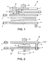
- FIG. figure 1 A double-hook mechanism already commercialized and using two coaxial coil springs to accumulate the energy necessary for closing and opening the switch is shown schematically in FIG. figure 1 .
- the frame of said command, as well as the switch of high or medium voltage switchgear are not shown: the movements and rotational connections of the various elements are described below with reference to the fixed frame.
- unrepresented rotational coupling means are arranged between the opening wheel 3 and the exit / closure wheel 4 such that beyond a rotation of the opening wheel 3 counterclockwise, the latter rotates in the same direction the closing output wheel 4.
- the mechanism M is in an initial state corresponding to the open switch.
- the springs 5, 6 are disarmed, the closing finger 8 hooks the wheel of exit / closure 4 while the opening finger 7 is free.
- the mechanism M In this locking position, the mechanism M is in a state corresponding to the open switch, the springs 5, 6 compressed (or armed) and the gripping fingers 7, 8 respectively hooked on the opening wheel 3 and the exit / exit wheel 4.
- the closing finger 8 is automatically attached to the output wheel 4.
- the new state of the fully disarmed mechanism therefore corresponds to the initial state, that is to say with the open switch, the springs relaxed or 5, 6, the fastening gripping finger 8 in engagement with the closing wheel 4 and the opening gripping finger 7 free.
- This mechanism M has the particular advantage of providing a maneuver cocking and closing in the same direction (clockwise).
- the mechanism M thus provides for a disengagement or in other words a disengagement between the cocking axis 20 and the light 11 made in the opening wheel 1.
- the mechanism M according to the state of the art is not completely satisfactory because, it is complex to achieve, includes a high number of parts with in particular a stack of parts too important detrimental to cost and space of the mechanism. This stack of parts is due to the presence of the rotary arming system 2, the arming pin 20 which serves thus uncoupling or disengagement between the manual operating lever (and the opening wheel 1 which is connected thereto by splines) and the rest of the mechanism.
- the inventors have judiciously thought to reduce the number of layers of rotating parts to two (instead of four) by integrating the functions of opening, arming, and control on the same wheel and incorporating disengagement or disengagement means at the end of the arming stroke between the operating lever and the combined wheel on the thickness of the latter.
- the mechanism constitutes a double-hooking mechanism and the attachment means consist of two separate fingers, one of which is a closing engagement finger pivotally mounted opposite the closing wheel and able to lock it in a compression position of the closing spring, the other said opening hooking finger pivotally mounted opposite the opening wheel and adapted to block it in a position of compression of the opening spring.
- the opening finger and the closing finger are pivotally mounted on the same axis.
- a double latching mechanism according to the invention can be particularly used in the so-called "normal / emergency" applications that are encountered when part of an electrical network must always be supplied permanently (for example hospitals).
- the part of the electrical network comprises two separate power sources, one being active while the other remains inactive.
- the main source active in normal conditions fails, its associated switch opens while the so-called emergency switch closes under the action of the release of the closing energy of the double latching mechanism which is dedicated.
- the main source is restored, its switch is closed and the emergency switch is then automatically re-opened by releasing the opening energy of the dedicated double latching mechanism.
- the closing fastening means can be released automatically at the end of the arming maneuver. This can be made possible for example by ejection of a closing finger. We do so somehow a simple snap mechanism by making the closing snap temporarily.
- a simple snap mechanism according to the invention thus has, after a closing of the switch, immediately after the arming phase, enough energy to be able to open the switch by releasing an opening hooking means. .
- the main application of this type of simple snap mechanism is the fuse-protected switches whose melting causes mechanical actuation of the mechanism, the latter opening the switch with the appropriate switch disconnector equipment equipment.
- the means of coupling and uncoupling at the end of arming between the manual lever and the combined opening, arming and control wheel which are integrated on the thickness of the latter advantageously comprise a fixed mechanical stop and a finger said control finger pivotally mounted on the combined wheel between two positions one said control position in which it delimits a space with the combined wheel inside a portion of the manual lever can be inserted by being locked in rotation to achieve the coupling and the other said so-called ejection position in which the portion of the manual lever is free to perform the uncoupling at the end of arming, the passage from the control position to the ejection position being caused by the setting in support of the control finger or a member secured to the control finger on the mechanical stop after a lever rotation stroke manual that allowed the compression of the springs opening and closing and their attachment.
- the bearing on the mechanical stop is preferably carried out by direct contact of a lever part which is fixed on the control finger, the lever arm between the fulcrum of the lever on the stop and the point of attachment. from the lever to the control finger being made so as to reduce to a predetermined value, the effort at the end of the manual cocking lever.
- the use of a lever arm system adapted with the control finger significantly reduces the forces at the end of manual arming lever at a predetermined value typically of the order of 250N. This takes into account the fact that by technical specification, the effort at the end of the manual arming lever must not exceed a value of the order of 250N.
- the length of the manual arming lever must not increase the size of the control functional unit which comprises the mechanism according to the invention, which means that it is not possible to increase this length to reduce efforts.
- At least one wheel or both wheels may be made of thermoplastic material.
- the invention also relates to high or medium voltage electrical equipment provided with at least one switch, comprising a control provided with a hook mechanism as described above.
- the double latching mechanism (M) according to the state of the art has already been commented on above and will not be discussed below.
- the mechanism according to the invention Mi is in an initial state corresponding to the open switch.
- the springs 5, 6 are disarmed, the closing finger 8 catches the exit / closure wheel 4 while the opening finger 7 is free.
- the closing finger 8 is automatically attached to the output wheel 4.
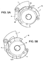
- the mechanism according to the invention is in a state corresponding to the open switch, the two springs of opening 5 and closing 6 released or disarmed, the closing gripping finger 8 hooked on the closing wheel 4 and the gripping finger 7 of free opening ( Figure 5B ).
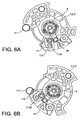
- the pin portion 90 of the manual lever 9 is housed in a space S delimited between a control finger 11 pivotally mounted on the wheel 1, 2, 3 and the latter, the finger 11 being moreover in contact with the wheel 1, 2, 3 in this nearest command position.
- This control finger 11 is integrated completely on the height E of the wheel 1, 2, 3.
- a lever member 110 is attached to the finger 11.
- Another abutment member 111 is attached to the frame not shown. This stop 111 is also completely integrated on the height E of the wheel 1, 2, 3.
- the pallet 110 bears directly against the fixed stop 111 ( Figure 6B ).
- the rotation stroke is of the order of 65 °.
- the attachment of the wheel 1, 2, 3 is then achieved by the opening hooking finger 7.
- the kinematics of the double latching mechanism (Mi) according to the invention has been successfully tested using a kinematic software.
Landscapes
- Mechanisms For Operating Contacts (AREA)
- Driving Mechanisms And Operating Circuits Of Arc-Extinguishing High-Tension Switches (AREA)
Description
L'invention concerne le domaine des commandes d'appareillages électriques à haute ou moyenne tension munis au moins d'un interrupteur.The invention relates to the field of control of electrical equipment with high or medium voltage provided with at least one switch.
Les appareillages visés par l'invention peuvent comporter jusqu'à trois interrupteurs à fonction différente : interrupteur de courant, sectionneur de barre, sectionneur de terre.The equipment covered by the invention may include up to three switches with different function: current switch, bar switch, earthing switch.
L'invention a trait plus particulièrement aux commandes qui comprennent un mécanisme à accrochage dont le désarmement est apte à provoquer un cycle de fermeture/ouverture d'au moins un interrupteur en exploitation de l'appareillage électrique.The invention relates more particularly to the controls which comprise a hooking mechanism whose disarming is capable of causing a closing / opening cycle of at least one operating switch of the electrical equipment.
L'invention vise à proposer une nouvelle structure du mécanisme à accrochage.The invention aims to propose a new structure of the snap mechanism.
Une commande d'un appareillage électrique haute ou moyenne tension muni d'au moins un interrupteur comprend un mécanisme appelé usuellement mécanisme à double accrochage.A control of a high or medium voltage switchgear equipped with at least one switch comprises a mechanism usually called a double snap mechanism.
Les mécanismes dits à double accrochage d'une commande d'appareillage haute ou moyenne tension comprenant au moins un interrupteur, présentent comme caractéristiques de fonctionnement, les phases suivantes :
- on arme le mécanisme (on stocke de l'énergie pour effectuer les manoeuvres de fermeture et d'ouverture d'au moins un interrupteur de l'appareillage),
- on ferme l'interrupteur en libérant une partie de l'énergie stockée dans le mécanisme (on libère un accrochage dit accrochage de fermeture),
- on ouvre l'interrupteur en libérant le reste de l'énergie stockée (on libère l'accrochage dit accrochage d'ouverture).
- the mechanism is armed (energy is stored to perform the closing and opening operations of at least one switch of the apparatus),
- the switch is closed by releasing a part of the energy stored in the mechanism (it releases a hooking said closing hook),
- we open the switch by releasing the rest of the stored energy (we release the hooking said opening snap).
Ainsi, les mécanismes à double accrochage permettent de stocker de l'énergie pour effectuer deux manoeuvres d'au moins un interrupteur de l'appareillage électrique qui en est muni: une manoeuvre de fermeture puis une manoeuvre d'ouverture.Thus, the double latching mechanisms can store energy to perform two operations of at least one switch of the electrical equipment which is provided with a closing maneuver and an opening maneuver.
Un type connu des mécanismes à double accrochage est celui comprenant deux ressorts en spirale, présentant typiquement une forte raideur pour l'application haute ou moyenne tension. Ils sont comprimés lors d'une manoeuvre dite « d'armement » qui peut être réalisée manuellement (avec un levier) et/ou motorisée. L'armement de ce mécanisme est obtenu, pour des raisons normatives, par rotation selon un même sens de rotation.A known type of double-hook mechanisms is that comprising two spiral springs, typically having a high stiffness for high or medium voltage application. They are compressed during a maneuver called "arming" that can be performed manually (with a lever) and / or motorized. The arming of this mechanism is obtained, for normative reasons, by rotation in the same direction of rotation.
Les mécanismes comprenant deux ressorts à spirales coaxiaux sont privilégiés par rapport à ceux comprenant un (ou deux) ressort(s) de compression du fait qu'ils permettent d'une part de concevoir un système compact et d'autre part d'obtenir une distribution d'énergie idéale puisque le couple fourni par chacun des ressorts à spirales est maximal en début de manoeuvre (lorsque le ressort est comprimé au maximum) et qu'il est toujours idéalement orienté (effort radial nul).The mechanisms comprising two coaxial coil springs are preferred over those comprising one (or two) compression spring (s) because they make it possible on the one hand to design a compact system and on the other hand to obtain a ideal energy distribution since the torque supplied by each of the spiral springs is maximum at the beginning maneuver (when the spring is compressed to the maximum) and that it is always ideally oriented (zero radial force).
Un mécanisme à double accrochage déjà commercialisé et utilisant deux ressorts à spirales coaxiaux pour accumuler l'énergie nécessaire pour la fermeture et l'ouverture de l'interrupteur est représenté schématiquement en
Ce mécanisme connu M comprend, selon une direction d'empilement de pièces, les éléments principaux suivants:
- un premier organe rotatif dit roue de
commande 1 qui est solidaire d'un axe dit axe decommande 10, - un deuxième organe rotatif, dit système d'armement 2 qui est adapté pour être accouplé en rotation à la roue de
commande 1 par l'intermédiaire d'un deuxième axe dit axe d'armement 20 susceptible de coulisser dans unelumière 11 pratiquée dans la roue decommande 1, - un troisième organe rotatif dit roue d'ouverture 3 solidaire du système d'armement 2 par un troisième axe dit d'ouverture 30 emboité dans un
logement 21 pratiqué dans le système d'armement 2, - un quatrième organe rotatif dit roue de sortie /
fermeture 4 comprenant unquatrième axe 40 dit axe de liaison permanente avec au moins un interrupteur de l'appareillage haute ou moyenne tension lorsque celui-ci est en configuration installée, - deux ressorts à
spirale fermeture 6 est apte à fermer l'interrupteur de l'appareillage en se relâchant depuis un état comprimé; les deuxressorts fermeture 6 est fixée à la roue defermeture 4, - deux
doigts fermeture 8 est apte à accrocher la roue defermeture 6 depuis un état comprimé du ressort defermeture 6.
- a first rotary member, called the
control wheel 1, which is integral with an axis referred to as thecontrol axis 10, - a second rotary member, called the
cocking system 2, which is adapted to be rotatably coupled to thecontrol wheel 1 via a second axis, called thecocking axis 20, which can slide in aslot 11 formed in thecontrol wheel 1, - a third rotary member said
opening wheel 3 secured to thecocking system 2 by a third axis called opening 30 nested in ahousing 21 formed in thecocking system 2, - a fourth rotary member called exit /
closure wheel 4 comprising afourth axis 40 said permanent connection axis with at least one switch of the high or medium voltage switchgear when the latter is in the installed configuration, - two
coil springs spring 5 is adapted to open the switch of the apparatus by relaxing from a compressed state and the other saidclosing spring 6 is adapted to close the switch of the equipment by relaxing from a compressed state; the twosprings opening wheel 3 while the other end of theopening spring 5 is fixed to the frame of the mechanism and the other end of theclosing spring 6 is fixed at theclosing wheel 4, - two
fingers finger 7 is adapted to hook theopening wheel 3 in a compressed state of theopening spring 5 and the other said finger ofclosing catch 8 is able to hook theclosing wheel 6 from a compressed state of theclosing spring 6.
En outre, des moyens d'accouplement en rotation non représentés sont agencés entre la roue d'ouverture 3 et la roue de sortie/fermeture 4 tels que au-delà d'une rotation de la roue d'ouverture 3 dans le sens antihoraire, cette dernière entraîne en rotation dans le même sens la roue de sortie fermeture 4.In addition, unrepresented rotational coupling means are arranged between the
Tel que schématisé en
Le fonctionnement d'armement manuel du mécanisme M selon l'état de l'art est le suivant :
- mise en place d'un levier manuel de manoeuvre sur l'axe de commande 10 (le levier et l'axe de commande sont liés en rotation par un système de cannelure non représenté),
- rotation du levier manuel de manoeuvre dans le sens horaire afin de comprimer les deux
ressorts commande 1 liée en rotation conduit à une rotation du système d'armement 2 une fois l'axe de commande en butée dans lalumière 11 et à la rotation de la roue d'ouverture 3. La compression simultanée des deuxressorts 5, 6 a lieu jusqu'à ce qu'une partie de la roue d'ouverture 3 vient à être accrochée par le doigt d'ouverture 7 (le doigt defermeture 8 étant initialement accroché). En effet, l'agencement de la partie accrochage (protubérance ou encoche) prévue sur la roue d'ouverture 3 est réalisé pour que dans une position donnée le doigt d'accrochage d'ouverture 7 vienne s'accrocher automatiquement sur ladite partie d'accrochage. Lesroues
- setting up a manual operating lever on the control shaft 10 (the lever and the control shaft are connected in rotation by a not shown spline system),
- rotation of the manual operating lever in the clockwise direction to compress the two
springs control wheel 1 connected in rotation leads to a rotation of thecocking system 2 once the axis in which the twosprings opening wheel 3 is hung up. by the opening finger 7 (theclosing finger 8 being initially hooked). Indeed, the arrangement of the attachment part (protuberance or notch) provided on theopening wheel 3 is designed so that in a given position the opening hookingfinger 7 comes to hook automatically on said part of hanging. Thewheels
Dans cette position de blocage, le mécanisme M est dans un état correspondant à l'interrupteur ouvert, les ressorts 5, 6 comprimés (ou armés) et les doigts d'accrochage 7, 8 respectivement accrochés sur la roue d'ouverture 3 et la roue de sortie/fermeture 4.In this locking position, the mechanism M is in a state corresponding to the open switch, the
Un cycle ou manoeuvre de fermeture/ouverture d'un interrupteur lié à une commande équipée d'un mécanisme M est le suivant :
- décrochage du doigt de
fermeture 8 par un dispositif approprié (manuel du type bouton-poussoir ou automatique par remontée mécanique de l'information de fusion d'un fusible), ce qui permet la détente du ressort defermeture 6 et donc la rotation de la roue desortie 4 dans le sens horaire. La roue desortie 4 étant liée à l'interrupteur par l'axe desortie 40, sa rotation dans le sens horaire va donc conduire à la fermeture de l'interrupteur, - décrochage du doigt d'ouverture 7 également par un dispositif approprié, ce qui permet la détente du ressort d'ouverture 5 et donc la rotation de la roue d'ouverture 3 dans le sens antihoraire qui par l'intermédiaire des moyens d'accouplement entraîne la roue de sortie/
fermeture 4 dans ce même sens. L'interrupteur lié à la roue de sortie/fermeture 4 est également entraîné en rotation dans ce même sens.
- releasing of the
closing finger 8 by an appropriate device (manual push-button type or automatic by mechanical rise of the fusing information of a fuse), which allows the relaxation of theclosing spring 6 and therefore the rotation of theexit wheel 4 clockwise. Theoutput wheel 4 being connected to the switch by theoutput shaft 40, its rotation in the clockwise direction will therefore lead to the closing of the switch, - stalling the
opening finger 7 also by a suitable device, which allows theopening spring 5 to relax and thus the rotation of theopening wheel 3 in the counterclockwise direction which, via the coupling means, causes the exit /closure wheel 4 in the same direction. The switch linked to the exit /closure wheel 4 is also rotated in the same direction.
En fin de course, le doigt de fermeture 8 vient se raccrocher automatiquement sur la roue de sortie 4. Le nouvel état du mécanisme complètement désarmé correspond donc à l'état initial, c'est-à-dire avec l'interrupteur ouvert, les ressorts détendus ou 5, 6, le doigt d'accrochage de fermeture 8 en prise avec la roue de fermeture 4 et le doigt d'accrochage d'ouverture 7 libre.At the end of the race, the
Ce mécanisme M selon l'art antérieur présente notamment l'avantage de proposer une manoeuvre d'armement et de fermeture dans le même sens (sens horaire).This mechanism M according to the prior art has the particular advantage of providing a maneuver cocking and closing in the same direction (clockwise).
Il présente par ailleurs l'avantage de répondre aux deux conditions normatives selon lesquelles :
- l'armement à la fois du ressort d'ouverture 5 et du ressort de
fermeture 6 est réalisé en en une seule manoeuvre manuelle, - en cas de fermeture de l'interrupteur sur court-circuit par exemple, le mécanisme doit être capable d'être ré ouvert immédiatement sans risque de blesser un opérateur présent à proximité de la commande sur laquelle le levier manuel serait toujours présent : en effet, lors d'une réouverture il y a alors le risque que le levier toujours présent soit ramené en arrière par le mouvement dans le même sens de la roue d'ouverture.
- the arming of both the
opening spring 5 and theclosing spring 6 is achieved in a single manual operation, - if the switch is closed on short circuit for example, the mechanism must be able to be reopened immediately without risk of injuring an operator present near the control on which the manual lever would always be present: indeed, when reopening then there is the risk that the always present lever is brought back by the movement in the same direction of the opening wheel.
Pour répondre à cette dernière condition normative, le mécanisme M selon l'état de l'art prévoit donc un désaccouplement ou autrement dit un débrayage entre l'axe d'armement 20 et la lumière 11 pratiquée dans la roue d'ouverture 1.To meet this last normative condition, the mechanism M according to the state of the art thus provides for a disengagement or in other words a disengagement between the cocking
Le mécanisme M selon l'état de l'art n'est pas complètement satisfaisant car, il s'avère complexe à réaliser, comprend un nombre élevé de pièces avec en particulier un empilement de pièces trop important nuisible au coût et à l'encombrement du mécanisme. Cet empilement de pièces est dû à la présence du système d'armement rotatif 2, de l'axe d'armement 20 qui sert donc au désaccouplement ou débrayage entre le levier de manoeuvre manuel (et de la roue d'ouverture 1 qui lui est liée par cannelures) et le reste du mécanisme.The mechanism M according to the state of the art is not completely satisfactory because, it is complex to achieve, includes a high number of parts with in particular a stack of parts too important detrimental to cost and space of the mechanism. This stack of parts is due to the presence of the
Or, plus l'encombrement du mécanisme est important, plus il peut s'avérer délicat d'intégrer dans la commande complète des fonctions annexes (bobine de déclenchement, indication, verrouillages...).However, the larger the size of the mechanism, the more difficult it may be to integrate in the complete control ancillary functions (trigger coil, indication, locks ...).
Le but de l'invention est alors de proposer un nouveau mécanisme à accrochage de commande d'appareillage haute ou moyenne tension comprenant au moins un interrupteur qui réponde aux exigences suivantes:
- accumuler l'énergie nécessaire aux manoeuvres de fermeture et d'ouverture de l'interrupteur en une seule opération,
- réaliser une manoeuvre d'armement de l'énergie nécessaire aux manoeuvres de fermeture et d'ouverture proprement dites selon le même sens,
- délivrer un couple maximal en début de manoeuvre d'ouverture ou de fermeture,
- réduire le coût,
- être le plus compact possible afin de faciliter l'intégration des fonctions annexes (bobine de déclenchement, indication, verrouillages...).
- accumulate the energy required for the closing and opening operations of the switch in a single operation,
- perform a maneuver arming the energy necessary for closing and opening operations proper in the same direction,
- deliver maximum torque at the beginning of the opening or closing maneuver,
- reduce the cost,
- be as compact as possible in order to facilitate the integration of ancillary functions (trigger coil, indication, interlocks ...).
Pour ce faire, l'invention a pour objet un mécanisme dit à accrochage de commande d'appareillage électrique haute ou moyenne tension muni d'au moins un interrupteur comprenant :
- un arbre de commande,
- un premier organe rotatif dit roue combinée de commande, d'armement et d'ouverture, solidaire de l'arbre de commande et adapté pour être mis en rotation par un levier manuel,
- un deuxième organe rotatif dit roue de sortie/ouverture montée libre en rotation autour de l'arbre de commande et à laquelle est fixé un axe,
- deux ressorts en spirale dont l'un dit ressort d'ouverture est apte à ouvrir l'interrupteur de l'appareillage en se relâchant depuis un état comprimé et dont l'autre dit ressort de fermeture est apte à fermer l'interrupteur de l'appareillage en se relâchant depuis un état comprimé, les extrémités intérieures du ressort d'ouverture et de fermeture étant chacune fixées à l'arbre de commande tandis que l'extrémité extérieure du ressort d'ouverture est fixée au bâti du mécanisme et l'extrémité extérieure du ressort de fermeture est fixée à la roue de fermeture,
- des moyens d'accrochage de fermeture et d'ouverture, montés pivotants entre deux états, l'un des états permettant le blocage de la roue de sortie/fermeture puis de la roue combinée de commande, d'armement et d'ouverture par les compressions simultanées du ressort de fermeture et du ressort d'ouverture par l'intermédiaire du levier manuel en rotation dans un sens, l'autre des états permettant successivement la rotation de la roue de sortie/fermeture puis de la roue combinée de commande, d'armement et d'ouverture dans le sens opposé par les relâchements successifs du ressort de fermeture et d'ouverture,
- des moyens d'accouplement entre le levier manuel et la roue combinée de commande, d'armement et d'ouverture, lesdits moyens d'accouplement étant intégrés sur l'épaisseur de la roue combinée de commande, d'armement et d'ouverture et conçus pour réaliser un désaccouplement entre ladite roue et le levier manuel en fin de course d'armement.
- a control shaft,
- a first rotary member, said combined control, cocking and opening wheel, integral with the control shaft and adapted to be rotated by a manual lever,
- a second rotary member, called an exit / opening wheel mounted free to rotate around the control shaft and to which an axis is fixed,
- two spiral springs, one of which said opening spring is able to open the switch of the apparatus by relaxing from a compressed state and the other said closing spring is able to close the switch of the apparatus by releasing from a compressed state, the inner ends of the opening and closing spring being each attached to the drive shaft while the outer end of the opening spring is attached to the mechanism frame and the end outer of the closing spring is attached to the closing wheel,
- fastening means for closing and opening pivotally mounted between two states, one of the states allowing the blocking of the exit / closure wheel and then the combined wheel for controlling, cocking and opening by the simultaneous compression of the closing spring and the opening spring by means of the manual lever rotated in one direction, the other of the states successively allowing the rotation of the exit / closure wheel and then the combined control wheel, d arming and opening in the opposite direction by the successive releases of the closing and opening spring,
- coupling means between the manual lever and the combined control wheel, arming and opening, said coupling means being integrated on the thickness of the combined wheel control, arming and opening and designed to disengage between said wheel and the manual lever at the end of the arming stroke.
Par rapport au mécanisme à double accrochage M selon l'état de l'art représenté en
Toutes choses égales par ailleurs, les gains économique et en volume sont donc indéniables puisque:
- d'une part, il n'y a plus qu'à fabriquer une roue combinée d'armement, d'ouverture et de commande au lieu de trois différentes comme dans l'art antérieur,
- d'autre part, l'épaisseur totale du mécanisme (encombrement selon l'axe de rotation des roues) est réduite.
- on the one hand, there is only to manufacture a combined arming, opening and control wheel instead of three different as in the prior art,
- on the other hand, the total thickness of the mechanism (size along the axis of rotation of the wheels) is reduced.
Selon un mode avantageux de l'invention, le mécanisme constitue un mécanisme à double accrochage et les moyens d'accrochage consistent en deux doigts distincts, l'un dit doigt d'accrochage de fermeture monté pivotant en regard de la roue de fermeture et apte à bloquer celle-ci dans une position de compression du ressort de fermeture, l'autre dit doigt d'accrochage d'ouverture monté pivotant en regard de la roue d'ouverture et apte à bloquer celle-ci dans une position de compression du ressort d'ouverture.According to an advantageous embodiment of the invention, the mechanism constitutes a double-hooking mechanism and the attachment means consist of two separate fingers, one of which is a closing engagement finger pivotally mounted opposite the closing wheel and able to lock it in a compression position of the closing spring, the other said opening hooking finger pivotally mounted opposite the opening wheel and adapted to block it in a position of compression of the opening spring.
De préférence, le doigt d'ouverture et le doigt de fermeture sont montés pivotants sur un même axe.Preferably, the opening finger and the closing finger are pivotally mounted on the same axis.
Un mécanisme à double accrochage selon l'invention peut être particulièrement utilisé dans les applications dites « normal/secours » qui se rencontrent lorsqu'une partie d'un réseau électrique doit impérativement être alimentée en permanence (cas des hôpitaux par exemple). Dans ce cas, la partie du réseau électrique comprend deux sources d'alimentation électriques distinctes, l'une étant active tandis que l'autre reste inactive. Ainsi, lorsque la source principale active en conditions normales tombe en panne, son interrupteur associé s'ouvre tandis que l'interrupteur dit de secours se ferme sous l'action de la libération de l'énergie de fermeture du mécanisme à double accrochage qui lui est dédié. Lorsque la source principale est rétablie, son interrupteur est refermé et l'interrupteur de secours est alors automatiquement ré-ouvert par la libération de l'énergie d'ouverture du mécanisme de double accrochage dédié.A double latching mechanism according to the invention can be particularly used in the so-called "normal / emergency" applications that are encountered when part of an electrical network must always be supplied permanently (for example hospitals). In this case, the part of the electrical network comprises two separate power sources, one being active while the other remains inactive. Thus, when the main source active in normal conditions fails, its associated switch opens while the so-called emergency switch closes under the action of the release of the closing energy of the double latching mechanism which is dedicated. When the main source is restored, its switch is closed and the emergency switch is then automatically re-opened by releasing the opening energy of the dedicated double latching mechanism.
Selon une alternative, le moyen d'accrochage de fermeture peut être libéré automatiquement en fin de manoeuvre d'armement. Cela peut être rendu possible par exemple par éjection d'un doigt de fermeture. On réalise ainsi en quelque sorte un mécanisme à simple accrochage en rendant l'accrochage de fermeture temporaire. Un mécanisme à simple accrochage selon l'invention possède ainsi, après une fermeture de l'interrupteur, immédiatement après la phase d'armement, suffisamment d'énergie pour pouvoir ouvrir l'interrupteur par libération d'un moyen d'accrochage d'ouverture. L'application principale de ce type de mécanisme à simple accrochage vise les interrupteurs protégés par fusible dont la fusion provoque un actionnement mécanique du mécanisme, ce dernier ouvrant l'interrupteur avec le cas échéant le sectionneur qui équipe l'appareillage.According to an alternative, the closing fastening means can be released automatically at the end of the arming maneuver. This can be made possible for example by ejection of a closing finger. We do so somehow a simple snap mechanism by making the closing snap temporarily. A simple snap mechanism according to the invention thus has, after a closing of the switch, immediately after the arming phase, enough energy to be able to open the switch by releasing an opening hooking means. . The main application of this type of simple snap mechanism is the fuse-protected switches whose melting causes mechanical actuation of the mechanism, the latter opening the switch with the appropriate switch disconnector equipment equipment.
Les moyens d'accouplement et de désaccouplement en fin d'armement entre le levier manuel et la roue combinée d'ouverture, d'armement et de commande qui sont intégrés sur l'épaisseur de cette dernière comprennent avantageusement une butée mécanique fixe et un doigt dit doigt de commande monté pivotant sur la roue combinée entre deux positions l'une dite position de commande dans laquelle il délimite un espace avec la roue combinée à l'intérieur une partie du levier manuel peut s'insérer en étant bloquée en rotation pour réaliser l'accouplement et l'autre dite position dite d'éjection dans laquelle la partie du levier manuel est libre pour réaliser le désaccouplement en fin d'armement, le passage de la position de commande à la position d'éjection étant provoqué par la mise en appui du doigt de commande ou d'un élément solidaire du doigt de commande sur la butée mécanique après une course de rotation du levier manuel ayant permis la compression des ressorts d'ouverture et de fermeture et leur accrochage.The means of coupling and uncoupling at the end of arming between the manual lever and the combined opening, arming and control wheel which are integrated on the thickness of the latter advantageously comprise a fixed mechanical stop and a finger said control finger pivotally mounted on the combined wheel between two positions one said control position in which it delimits a space with the combined wheel inside a portion of the manual lever can be inserted by being locked in rotation to achieve the coupling and the other said so-called ejection position in which the portion of the manual lever is free to perform the uncoupling at the end of arming, the passage from the control position to the ejection position being caused by the setting in support of the control finger or a member secured to the control finger on the mechanical stop after a lever rotation stroke manual that allowed the compression of the springs opening and closing and their attachment.
La mise en appui sur la butée mécanique est réalisée de préférence par contact direct d'une pièce formant levier qui est fixée sur le doigt de commande, le bras de levier entre le point d'appui du levier sur la butée et le point de fixation du levier au doigt de commande étant réalisé de manière à réduire à une valeur prédéterminée, l'effort en bout de levier d'armement manuel. L'utilisation d'un système de bras de levier adapté avec le doigt de commande permet de réduire significativement les efforts en bout de levier manuel d'armement à une valeur prédéterminée typiquement de l'ordre de 250N. Cela tient compte du fait que par spécification technique, l'effort en bout de levier d'armement manuel ne doit pas excéder une valeur de l'ordre de 250N. Or, la longueur du levier manuel d'armement ne doit pas augmenter l'encombrement de l'unité fonctionnelle de commande qui comprend le mécanisme selon l'invention, ce qui signifie qu'il n'est pas possible d'augmenter cette longueur pour réduire les efforts.The bearing on the mechanical stop is preferably carried out by direct contact of a lever part which is fixed on the control finger, the lever arm between the fulcrum of the lever on the stop and the point of attachment. from the lever to the control finger being made so as to reduce to a predetermined value, the effort at the end of the manual cocking lever. The use of a lever arm system adapted with the control finger significantly reduces the forces at the end of manual arming lever at a predetermined value typically of the order of 250N. This takes into account the fact that by technical specification, the effort at the end of the manual arming lever must not exceed a value of the order of 250N. However, the length of the manual arming lever must not increase the size of the control functional unit which comprises the mechanism according to the invention, which means that it is not possible to increase this length to reduce efforts.
Au moins une roue ou les deux roues (roue combinée d'armement, d'ouverture et de commande et roue de sortie/fermeture) selon l'invention peu (ven) t être réalisée(s) en matière thermoplastique.At least one wheel or both wheels (combined arming, opening and control wheel and exit / closing wheel) according to the invention may be made of thermoplastic material.
L'invention concerne également un appareillage électrique haute ou moyenne tension muni d'au moins d'un interrupteur, comprenant une commande muni d'un mécanisme à accrochage tel que décrit précédemment.The invention also relates to high or medium voltage electrical equipment provided with at least one switch, comprising a control provided with a hook mechanism as described above.
D'autres avantages et caractéristiques de l'invention ressortiront mieux à la lecture de la description détaillée d'un mode de réalisation de l'invention faite à titre illustratif en référence aux figures suivantes :
- la
figure 1 est une vue schématique en coupe axiale d'un mécanisme à double accrochage (M) selon l'état de l'art, - la
figure 2 est une vue schématique en coupe axiale d'un mécanisme à double accrochage (Mi) selon l'invention, - la
figure 3 est une vue en perspective du mécanisme (Mi) selon lafigure 2 , - les
figures 4A et 4B montrent en vue de dessus les étapes d'armement manuel du mécanisme (Mi) selon lesfigures 2 et 3 , - les
figures 5A et 5B montrent en vue de dessus les étapes d'un cycle de manoeuvre de fermeture/ouverture d'un interrupteur lié à une commande comprenant le mécanisme (Mi) selon lesfigures 2 et 3 , - la
figure 6 illustre en vue en perspective les moyens d'accouplement et de désaccouplement en fin d'armement entre le levier manuel d'armement et le mécanisme (Mi) selon l'invention, - Les
figures 6A à 6E illustrent schématiquement en vue de dessus les différentes étapes d'armement et de désaccouplement au niveau les moyens d'accouplement et de désaccouplement en fin d'armement entre le levier manuel d'armement et le mécanisme (Mi) selon lafigure 6 .
- the
figure 1 is a schematic view in axial section of a double latching mechanism (M) according to the state of the art, - the
figure 2 is a diagrammatic view in axial section of a double-hook mechanism (Mi) according to the invention, - the
figure 3 is a perspective view of the mechanism (Mi) according to thefigure 2 , - the
Figures 4A and 4B show in plan view the manual arming steps of the mechanism (Mi) according to thefigures 2 and3 , - the
Figures 5A and 5B show in plan view the steps of a closing / opening operation cycle of a switch linked to a control comprising the mechanism (Mi) according to thefigures 2 and3 , - the
figure 6 illustrates in perspective view the means of coupling and uncoupling at the end of arming between the manual cocking lever and the mechanism (Mi) according to the invention, - The
Figures 6A to 6E schematically illustrate in a view from above the different stages of arming and uncoupling at the level of the means of coupling and uncoupling at the end of arming between the manual arming lever and the mechanism (Mi) according to thefigure 6 .
Le mécanisme à double accrochage (M) selon l'état de l'art a déjà été commenté plus haut et ne le sera pas ci-après.The double latching mechanism (M) according to the state of the art has already been commented on above and will not be discussed below.
Par souci de clarté, les éléments communs au mécanisme à double accrochage selon l'état de l'art (M) et au mécanisme à double accrochage selon l'invention (Mi) sont désignés par les mêmes références numériques.For the sake of clarity, the elements common to the double latching mechanism according to the state of the art (M) and to the double latching mechanism according to the invention (Mi) are designated by the same reference numerals.
Le mécanisme selon l'invention (Mi) comprend, selon une direction d'empilement de pièces, les éléments principaux suivants :
- un premier organe rotatif dit roue de commande 1 qui est solidaire d'un axe dit axe de commande 10 adapté pour être mis en rotation par
un levier manuel 9. Cette roue fait comme expliqué ci-après également fonction de roue d'ouverture 2 et intègreun système d'armement 3, - un arbre de commande 12 solidaire de la roue 1, 2, 3 combinée de commande d'ouverture et d'armement,
- un deuxième organe rotatif dit roue de sortie /
fermeture 4comprenant un axe 40 dit axe de liaison permanente avec au moins un interrupteur de l'appareillage haute ou moyenne tension lorsque celui-ci est en configuration installée, - deux ressorts à spirale 5, 6 montés coaxiaux, l'un dit ressort d'ouverture 5 est apte à ouvrir l'interrupteur de l'appareillage en se relâchant depuis un état comprimé et dont l'autre dit ressort de fermeture 6 est apte à fermer au moins un interrupteur de l'appareillage en se relâchant depuis un état comprimé; les deux ressorts 5, 6 ont chacun une de leur extrémité intérieure fixée à l'arbre de commande 12 tandis que l'extrémité extérieure du ressort d'ouverture 5 est fixée au bâti du mécanisme et l'extrémité extérieure du ressort de fermeture 6 est fixée à la roue de fermeture 4,
- deux doigts 7, 8 montés pivotants dans le bâti, l'un dit doigt d'accrochage d'ouverture 7 est apte à accrocher la roue d'ouverture 1, 2, 3 dans un état comprimé du ressort d'ouverture 5 et l'autre dit doigt d'accrochage de fermeture 8 est apte accrocher la roue de fermeture 4 depuis un état comprimé du ressort de fermeture 6,
- des moyens 11, 110, 111 d'accouplement entre le levier
manuel figure 6 ).
- a first rotary member, called a
control wheel 1, which is integral with an axis referred to as acontrol shaft 10 adapted to be rotated by amanual lever 9. This wheel, as explained hereinafter, also functions as anopening wheel 2 and integrates anarming system 3, - a
control shaft 12 integral with thewheel - a second rotary member called an exit /
closure wheel 4 comprising anaxis 40 called permanent link axis with at least one switch of the high or medium voltage switchgear when the latter is in the installed configuration, - two
coil springs opening spring 5 is adapted to open the switch of the apparatus by relaxing from a compressed state and the other saidclosing spring 6 is adapted to closing at least one switch of the apparatus while relaxing from a compressed state; the twosprings control shaft 12 while the outer end of theopening spring 5 is fixed to the frame of the mechanism and the outer end of theclosing spring 6 is attached to theclosing wheel 4, - two
fingers opening hooking finger 7 is adapted to hook theopening wheel opening spring 5 and the other saidclosing hooking finger 8 is able to hook theclosing wheel 4 from a compressed state of theclosing spring 6, - coupling means 11, 110, 111 between the
manual lever figure 6 ).
Tel que schématisé en
Le fonctionnement d'armement manuel du mécanisme Mi est le suivant :
- mise en place du levier de
manoeuvre 9 dans l'axe de commande 10 comme expliqué par la suite en référence auxfigures 6 à 6E , - rotation du levier
manuel 9 de manoeuvre dans le sens horaire. Cette rotation du levier 9 et donc de la roue combinée d'armement, d'ouverture et de commande 1, 2, 3 et de l'arbre de commande 12 conduit à une compression des deux ressorts spirale 5, 6 (figure 4A ). La rotation du levier 9 s'interrompt lorsque le doigt d'ouverture est accroché et lorsque le levier est débrayé de la roue de commande. Dans cette position de blocage, le mécanisme Mi selon l'invention est dans un état correspondant à l'interrupteur ouvert, les ressorts 5, 6 comprimés (ou armés) et les doigts d'accrochage 7, 8 respectivement accrochés sur la roue combinée d'armement, de commande et d'ouverture 1 et sur la roue de sortie/fermeture 4.
- placing the operating
lever 9 in thecontrol shaft 10 as explained later with reference toFigures 6 to 6E , - rotation of the
manual lever 9 to maneuver clockwise. This rotation of thelever 9 and thus of the combined arming, opening andcontrol wheel control shaft 12 leads to a compression of the twospiral springs 5, 6 (Figure 4A ). The rotation of thelever 9 stops when the opening finger is hooked and when the lever is disengaged from the control wheel. In this locking position, the mechanism Mi according to the invention is in a state corresponding to the open switch, thesprings gripping fingers opening 1 and on the exit /exit wheel 4.
Un cycle de manoeuvre de fermeture/ouverture d'un interrupteur haute ou moyenne tension lié à une commande comprenant le mécanisme Mi selon l'invention est le suivant :
- décrochage ou déclenchement du doigt de fermeture 8 par pivotement et sortie du
pion 80 d'accrochage de la roue de fermeture 4, ce qui permet la détente du ressort de fermeture 6 et donc la rotation de la roue desortie 4 dans le sens horaire. La roue de sortie étant liée à l'interrupteur, sa rotation dans le sens horaire va donc conduire à la fermeture de l'interrupteur. Dans cette nouvelle position de blocage, le mécanisme selon l'invention est dans un état correspondant à l'interrupteur fermé, le ressort de fermeture 6 relâché ou désarmé, le ressort d'ouverture 5 comprimé ou armé, le doigt d'accrochage 8 de fermeture libéré et le doigt d'accrochage d'ouverture accroché sur la roue combinée d'armement, de commande et d'ouverture 1 (figure 5A ), - décrochage ou déclenchement du doigt d'ouverture 7 de l'encoche 100 de la roue combinée d'ouverture, de commande et d'armement 1 ce qui conduit à sa rotation dans le sens antihoraire. Les moyens d'accouplement 13, 41 entre la roue 1 et la roue de
sortie 4 sont agencés de sorte que, la rotation de la roue 1 dans le sens antihoraire entraîne également la rotation de la roue de sortie 4 (et donc de l'interrupteur qui lui est lié) dans ce même sens.
- stall or release of the
closing finger 8 by pivoting and output of thepin 80 for hooking theclosing wheel 4, which allows the relaxation of theclosing spring 6 and thus the rotation of theoutput wheel 4 in the clockwise direction. The output wheel being linked to the switch, its clockwise rotation will therefore lead to the closing of the switch. In this new locking position, the mechanism according to the invention is in a state corresponding to the closed switch, theclosing spring 6 released or disarmed, theopening spring 5 compressed or armed, thegripping finger 8 of released closure and the opening hooking finger hooked to the combined arming, control and opening wheel 1 (Figure 5A ) - stalling or triggering the
opening finger 7 of thenotch 100 of the combined opening wheel, control and arming 1 which leads to its rotation in the counterclockwise direction. The coupling means 13, 41 between thewheel 1 and theoutput wheel 4 are arranged so that the rotation of thewheel 1 in the counterclockwise direction also causes the rotation of the output wheel 4 (and therefore of the switch linked to it) in the same direction.
En fin de course, le doigt de fermeture 8 vient se raccrocher automatiquement sur la roue de sortie 4. Dans cette nouvelle position de blocage, le mécanisme selon l'invention est dans un état correspondant à l'interrupteur ouvert, les deux ressorts d'ouverture 5 et de fermeture 6 relâchés ou désarmés, le doigt d'accrochage 8 de fermeture accroché sur la roue de fermeture 4 et le doigt d'accrochage 7 d'ouverture libre (
Sur la
Sur cette figure, on voit que la partie pion 90 du levier manuel 9 est logée dans un espace S délimité entre un doigt de commande 11 monté pivotant sur la roue 1, 2, 3 et cette dernière, le doigt 11 étant par ailleurs en contact avec la roue 1, 2, 3 dans cette position la plus proche dite de commande.In this figure, it can be seen that the
Ce doigt de commande 11 est intégré complètement sur la hauteur E de la roue 1, 2, 3.This
Un élément formant levier 110 est fixé sur le doigt 11.A
Un autre élément formant butée 111 est fixé au bâti non représenté. Cette butée 111 est également complètement intégrée sur la hauteur E de la roue 1, 2, 3.Another
Lorsqu'un opérateur insère le levier d'armement manuel 9 dans la roue 1, 2, 3, le pion 90 vient se loger dans l'espace S.When an operator inserts the
L'opérateur fait tourner le levier manuel 9 dans le sens horaire comme expliqué ci-dessus (
Au bout d'une course de rotation donnée, la palette 110 vient en appui direct contre la butée fixe 111 (
Les actions conjuguées de la rotation de la roue 1, 2, 3 sous l'effet du couple transmis par l'opérateur au levier manuel 9 et donc à la roue 1, 2, 3 et de l'appui direct du levier 110 sur la butée mécanique 111 ont pour effets simultanés de continuer à mettre en rotation la roue 1, 2, 3 et de faire pivoter le levier 110 au niveau de la fixation 1100 du doigt de commande 11 sur la roue 1, 2, 3 (
Au bout d'une certaine course de rotation, le pivotement du levier 110 et donc du doigt de commande 11 met ce dernier dans une position dite d'éjection dans laquelle le pion 90 du levier 9 est libre car il n'est plus maintenu dans l'espace entre le doigt et la roue combinée 1, 2, 3 (
La cinématique du mécanisme à double accrochage (Mi) selon l'invention a été testée avec succès à l'aide d'un logiciel de cinématique.The kinematics of the double latching mechanism (Mi) according to the invention has been successfully tested using a kinematic software.
La tenue mécanique des principales pièces (roues 1 et 4, ressorts spirale 5, 6 et doigts d'ouverture 7 et de fermeture 8) a elle aussi été validée avec succès à l'aide du logiciel de simulation numérique commercialisé sous la dénomination « Ansys ».The mechanical strength of the main parts (
En outre, un prototype de mécanisme à double accrochage a lui aussi été testé avec succès.In addition, a prototype double-snap mechanism has also been successfully tested.
Le mécanisme à double accrochage selon l'invention Mi qui vient d'être décrit présente de nombreux avantages par rapport au mécanisme M selon l'état de l'art :
- sa chaîne cinématique étant très simple de réalisation, son rendement est élevé,
- le nombre d'empilement de pièces qui le constituent étant limité, sa compacité est accrue,
- le nombre de pièces qui le constituent étant limité, son coût est réduit.
- its kinematic chain being very simple to implement, its efficiency is high,
- the number of stack of parts that constitute it being limited, its compactness is increased,
- the number of parts constituting it being limited, its cost is reduced.
Claims (8)
- A latch mechanism (Mi) for a control device for high or medium voltage switchgear having at least one interrupter, the latching mechanism comprising:- a control shaft (12);- a first rotary member (1, 2, 3), referred to as a combined actuating, arming, and opening wheel, that is fastened to the control shaft (12) and adapted to be set in rotation by a manual key;- a second rotary member referred to as an output and closing wheel (4), mounted for free rotation around the control shaft (12), with an output shaft being fastened to the output and closing wheel;- two spiral springs (5, 6), one of which, referred to as the opening spring (5), is adapted to open the interrupter of the switchgear by being released from a compressed state, the other of which, referred to as the closing spring (6), is adapted to close the interrupter of the switchgear by being released from a compressed state, with each of the inner ends of the opening spring (5) and closing spring (6) being fastened to the control shaft (12), while the outer end of the opening spring (5) is fastened to the body of the mechanism and the outer end of the closing spring (6) is fastened to the closing wheel (4);- closing latch means (8) and opening latch means (7), both of which are mounted for pivoting movement between two states, one of which states is a state in which one said latch means is enabled to block movement of the output and closing wheel (4) and then of the combined actuating, arming, and opening wheel (1, 2, 3), by simultaneous compression of the closing spring (6) and opening spring (5), effected by rotation of the manual key in one direction, the other state permitting, in succession, the rotation of the output and closing wheel and the rotation of the combined actuating, arming, and opening wheel in the opposite direction by the release, in succession, of the closing spring (6) and the opening spring (5); and- coupling means (11, 110, 111) between the manual key (9) and the combined control, arming, and opening wheel, said coupling means being incorporated within the thickness (E) of the combined actuating, arming, and opening wheel, and being designed for uncoupling said combined wheel (1, 2, 3) from the manual key (9) at the end of the arming movement.
- A control mechanism (Mi) according to claim 1, constituting a double latch mechanism in which the latch means consist of two separate fingers, one of which, referred to as the closing latch finger (8), is mounted for pivoting movement facing the closing wheel, and is adapted to block movement of the closing wheel in a position in which the closing spring is compressed, the other of which, referred to as the opening latch finger (7), being mounted for pivoting movement facing the opening wheel and being adapted to block movement of the opening wheel in a position in which the opening spring is compressed.
- A double latch control mechanism (Mi) according to claim 2, wherein the opening finger (7) and the closing finger (8) are mounted for pivoting movement on a common axis.
- A control mechanism (Mi) according to claim 1, wherein the closing latch means is adapted to be released automatically at the end of an arming operation.
- A control mechanism (Mi) according to any preceding claims, wherein at least one of the wheels (1, 2, 3, or 4) is made of thermoplastic material.
- A control mechanism (Mi) according to any preceding claim, wherein the means for acting, at the end of an arming operation, to effect coupling and uncoupling between the manual key (9) and the combined opening, arming, and control wheel (1, 2, 3), which are incorporated within the thickness (E) of said combined wheel, comprise a stationary mechanical abutment (111) and a finger, referred to as the control finger (11), that is mounted for pivoting movement on the combined wheel between two positions, in one of which, referred to as the control position, a space (S) is defined with between the combined wheel (1, 2, 3), inside which a portion (90) of the manual key (9) is able to be inserted, being blocked against rotation so as thereby to effect said coupling, the other said position being referred to as the ejection position, in which said portion (90) of the manual key (9) is free to effect said uncoupling at the end of an arming operation, changing from the control position to the ejection position, being brought about by engagement of the control finger (11), or an element (110) fastened to the control finger, on the mechanical abutment (111) after a rotational movement of the manual key has caused the opening and closing springs to be compressed and latched.
- A control mechanism (Mi) according to claim 6, wherein said engagement on the mechanical abutment (111) is obtained by direct contact of a lever element (110) that is fastened on the control finger (11), the lever arm between the point of engagement of the lever element (110) on the control finger and the point at which the lever element (110) is fastened to the control finger being such as to reduce to a predetermined value the force on the end of the manual arming key (9).
- High or medium voltage switchgear having at least one interrupter, including a control device having a latch mechanism according to any one of claims 1 to 7.
Applications Claiming Priority (1)
| Application Number | Priority Date | Filing Date | Title |
|---|---|---|---|
| FR0950011A FR2940850B1 (en) | 2009-01-05 | 2009-01-05 | MECHANISM HAVING A HAND OR HIGH VOLTAGE EQUIPMENT CONTROL HAVING IMPROVED COMPACITY AND COST |
Publications (2)
| Publication Number | Publication Date |
|---|---|
| EP2204828A1 EP2204828A1 (en) | 2010-07-07 |
| EP2204828B1 true EP2204828B1 (en) | 2015-04-08 |
Family
ID=40996829
Family Applications (1)
| Application Number | Title | Priority Date | Filing Date |
|---|---|---|---|
| EP09180797.4A Not-in-force EP2204828B1 (en) | 2009-01-05 | 2009-12-28 | Mechanism for coupling a high- or medium-voltage switchgear control, with improved compactness and cost |
Country Status (4)
| Country | Link |
|---|---|
| EP (1) | EP2204828B1 (en) |
| CN (1) | CN101770879B (en) |
| ES (1) | ES2541463T3 (en) |
| FR (1) | FR2940850B1 (en) |
Families Citing this family (2)
| Publication number | Priority date | Publication date | Assignee | Title |
|---|---|---|---|---|
| FR3086455B1 (en) | 2018-09-20 | 2020-08-14 | Schneider Electric Ind Sas | ACTUATION SYSTEM FOR ELECTRICAL APPLIANCE SWITCH |
| FR3089049B1 (en) | 2018-11-26 | 2020-11-06 | Schneider Electric Ind Sas | MECHANISM FOR THE CLOSING AND OPENING COMMAND OF A POWER-CUTTING DEVICE FOR SWITCHES |
Family Cites Families (6)
| Publication number | Priority date | Publication date | Assignee | Title |
|---|---|---|---|---|
| US3672233A (en) * | 1970-07-06 | 1972-06-27 | Clare & Co C P | Actuator mechanism |
| DE7143984U (en) * | 1971-11-23 | 1972-02-03 | Siemens Ag | Drive for an electrical power switch |
| US20060087492A1 (en) * | 2004-09-01 | 2006-04-27 | Speed Tech Corp. | Fixture device for a roller construction module |
| EP1648212B1 (en) * | 2004-10-14 | 2007-03-07 | Research In Motion Limited | Method of mounting thumbwheel switch on printed circuit board and handheld electronic device incorporating same |
| US7368677B2 (en) * | 2005-12-14 | 2008-05-06 | Eaton Corporation | Reverse bias hatchet reset spring |
| US7351107B1 (en) * | 2007-01-03 | 2008-04-01 | Delphi Technologies, Inc. | One-piece electromagnetic shield having mechanical attachment features |
-
2009
- 2009-01-05 FR FR0950011A patent/FR2940850B1/en not_active Expired - Fee Related
- 2009-12-24 CN CN200910261384.1A patent/CN101770879B/en not_active Expired - Fee Related
- 2009-12-28 ES ES09180797.4T patent/ES2541463T3/en active Active
- 2009-12-28 EP EP09180797.4A patent/EP2204828B1/en not_active Not-in-force
Also Published As
| Publication number | Publication date |
|---|---|
| EP2204828A1 (en) | 2010-07-07 |
| FR2940850B1 (en) | 2011-02-11 |
| CN101770879B (en) | 2014-03-19 |
| FR2940850A1 (en) | 2010-07-09 |
| CN101770879A (en) | 2010-07-07 |
| ES2541463T3 (en) | 2015-07-20 |
Similar Documents
| Publication | Publication Date | Title |
|---|---|---|
| EP0997919B1 (en) | Switching device having a mechanical signaling element with three positions | |
| EP0951122B1 (en) | Control device for the discharge and the decoupling of an energy accumulator during the disconnection of a disconnectable circuit breaker | |
| EP3581742B1 (en) | Door flush handle and method of operating the same | |
| EP3221875B1 (en) | Tripping control system for breaking pole and switchgear | |
| FR2931131A1 (en) | RECOVERABLE COUPLING DEVICE AND TRIM CYLINDER | |
| EP1331658B1 (en) | Electrical switch apparatus with a motorised control and controlprocess of such an apparatus | |
| EP2842143B1 (en) | Control of spring(s) type for a high- or medium-voltage breaker furnished with a pawled free wheel coupling device | |
| EP2602804B1 (en) | Pole operating device in a medium-voltage electric control apparatus | |
| EP2204828B1 (en) | Mechanism for coupling a high- or medium-voltage switchgear control, with improved compactness and cost | |
| EP1653593B1 (en) | Dual output electromechanical motor | |
| EP2605256B1 (en) | Operating device of the motor-drive of the contact closing device reset device in an electric protection apparatus and apparatus comprising same | |
| EP2377139B1 (en) | Remote control device and circuit breaker with such device | |
| EP2189995B1 (en) | Control of high- or medium-voltage electrical switchgear with improved double latching and associated arming method | |
| EP1830117B1 (en) | Fire valve actuator | |
| FR3044162A1 (en) | ELECTRICAL PROTECTION APPARATUS AND PARTICULARLY MEDIUM VOLTAGE ELECTRIC CIRCUIT BREAKER | |
| EP3877252B1 (en) | Emergency opening device for an aircraft door, with rotary release | |
| WO2021239572A1 (en) | Emergency access device for vehicle opening panel having a retention lever and a pull wire | |
| EP1649478B1 (en) | Rotary engagement lock mechanism for automatic safety cutout | |
| EP2359379B1 (en) | Control mechanism for a remote-controlled cut-off device, cut-off device, and remote-controlled circuit breaker including such a mechanism | |
| EP2308067B1 (en) | Method of manually decocking a double-latching mechanism of a high-voltage or medium-voltage electrical control apparatus, and associated control | |
| FR3094341A1 (en) | Cabin door system for an airplane and airplane comprising at least one such cabin door system | |
| EP0354107B1 (en) | Fastening device for rapidly docking a structure thereto in a detachable way | |
| EP2575150A1 (en) | Motorization disengagement device of the reset device of the contact closing device in an electric protection apparatus and apparatus comprising same | |
| EP3657522B1 (en) | Mechanism for controlling the opening and closing of a current interruption device for an electrical switch | |
| EP3629351B1 (en) | Actuating system for electrical switching appliance |
Legal Events
| Date | Code | Title | Description |
|---|---|---|---|
| PUAI | Public reference made under article 153(3) epc to a published international application that has entered the european phase |
Free format text: ORIGINAL CODE: 0009012 |
|
| AK | Designated contracting states |
Kind code of ref document: A1 Designated state(s): AT BE BG CH CY CZ DE DK EE ES FI FR GB GR HR HU IE IS IT LI LT LU LV MC MK MT NL NO PL PT RO SE SI SK SM TR |
|
| AX | Request for extension of the european patent |
Extension state: AL BA RS |
|
| RIN1 | Information on inventor provided before grant (corrected) |
Inventor name: MALADEN, ROMAIN Inventor name: VICAIGNE, ANTOINE Inventor name: MARQUET, MATHIEU |
|
| 17P | Request for examination filed |
Effective date: 20101222 |
|
| RAP1 | Party data changed (applicant data changed or rights of an application transferred) |
Owner name: SCHNEIDER ELECTRIC ENERGY FRANCE |
|
| RAP1 | Party data changed (applicant data changed or rights of an application transferred) |
Owner name: SCHNEIDER ELECTRIC ENERGY FRANCE |
|
| GRAJ | Information related to disapproval of communication of intention to grant by the applicant or resumption of examination proceedings by the epo deleted |
Free format text: ORIGINAL CODE: EPIDOSDIGR1 |
|
| GRAP | Despatch of communication of intention to grant a patent |
Free format text: ORIGINAL CODE: EPIDOSNIGR1 |
|
| RIC1 | Information provided on ipc code assigned before grant |
Ipc: H01H 3/30 20060101AFI20140430BHEP |
|
| INTG | Intention to grant announced |
Effective date: 20140527 |
|
| GRAP | Despatch of communication of intention to grant a patent |
Free format text: ORIGINAL CODE: EPIDOSNIGR1 |
|
| INTG | Intention to grant announced |
Effective date: 20141103 |
|
| GRAS | Grant fee paid |
Free format text: ORIGINAL CODE: EPIDOSNIGR3 |
|
| GRAA | (expected) grant |
Free format text: ORIGINAL CODE: 0009210 |
|
| AK | Designated contracting states |
Kind code of ref document: B1 Designated state(s): AT BE BG CH CY CZ DE DK EE ES FI FR GB GR HR HU IE IS IT LI LT LU LV MC MK MT NL NO PL PT RO SE SI SK SM TR |
|
| REG | Reference to a national code |
Ref country code: GB Ref legal event code: FG4D Free format text: NOT ENGLISH |
|
| REG | Reference to a national code |
Ref country code: CH Ref legal event code: EP |
|
| REG | Reference to a national code |
Ref country code: IE Ref legal event code: FG4D Free format text: LANGUAGE OF EP DOCUMENT: FRENCH |
|
| REG | Reference to a national code |
Ref country code: AT Ref legal event code: REF Ref document number: 721091 Country of ref document: AT Kind code of ref document: T Effective date: 20150515 |
|
| REG | Reference to a national code |
Ref country code: DE Ref legal event code: R096 Ref document number: 602009030451 Country of ref document: DE Effective date: 20150521 |
|
| REG | Reference to a national code |
Ref country code: ES Ref legal event code: FG2A Ref document number: 2541463 Country of ref document: ES Kind code of ref document: T3 Effective date: 20150720 |
|
| REG | Reference to a national code |
Ref country code: AT Ref legal event code: MK05 Ref document number: 721091 Country of ref document: AT Kind code of ref document: T Effective date: 20150408 |
|
| REG | Reference to a national code |
Ref country code: NL Ref legal event code: VDEP Effective date: 20150408 |
|
| REG | Reference to a national code |
Ref country code: LT Ref legal event code: MG4D |
|
| PG25 | Lapsed in a contracting state [announced via postgrant information from national office to epo] |
Ref country code: NL Free format text: LAPSE BECAUSE OF FAILURE TO SUBMIT A TRANSLATION OF THE DESCRIPTION OR TO PAY THE FEE WITHIN THE PRESCRIBED TIME-LIMIT Effective date: 20150408 |
|
| PG25 | Lapsed in a contracting state [announced via postgrant information from national office to epo] |
Ref country code: PT Free format text: LAPSE BECAUSE OF FAILURE TO SUBMIT A TRANSLATION OF THE DESCRIPTION OR TO PAY THE FEE WITHIN THE PRESCRIBED TIME-LIMIT Effective date: 20150810 Ref country code: FI Free format text: LAPSE BECAUSE OF FAILURE TO SUBMIT A TRANSLATION OF THE DESCRIPTION OR TO PAY THE FEE WITHIN THE PRESCRIBED TIME-LIMIT Effective date: 20150408 Ref country code: NO Free format text: LAPSE BECAUSE OF FAILURE TO SUBMIT A TRANSLATION OF THE DESCRIPTION OR TO PAY THE FEE WITHIN THE PRESCRIBED TIME-LIMIT Effective date: 20150708 Ref country code: LT Free format text: LAPSE BECAUSE OF FAILURE TO SUBMIT A TRANSLATION OF THE DESCRIPTION OR TO PAY THE FEE WITHIN THE PRESCRIBED TIME-LIMIT Effective date: 20150408 Ref country code: HR Free format text: LAPSE BECAUSE OF FAILURE TO SUBMIT A TRANSLATION OF THE DESCRIPTION OR TO PAY THE FEE WITHIN THE PRESCRIBED TIME-LIMIT Effective date: 20150408 |
|
| PG25 | Lapsed in a contracting state [announced via postgrant information from national office to epo] |
Ref country code: LV Free format text: LAPSE BECAUSE OF FAILURE TO SUBMIT A TRANSLATION OF THE DESCRIPTION OR TO PAY THE FEE WITHIN THE PRESCRIBED TIME-LIMIT Effective date: 20150408 Ref country code: IS Free format text: LAPSE BECAUSE OF FAILURE TO SUBMIT A TRANSLATION OF THE DESCRIPTION OR TO PAY THE FEE WITHIN THE PRESCRIBED TIME-LIMIT Effective date: 20150808 Ref country code: AT Free format text: LAPSE BECAUSE OF FAILURE TO SUBMIT A TRANSLATION OF THE DESCRIPTION OR TO PAY THE FEE WITHIN THE PRESCRIBED TIME-LIMIT Effective date: 20150408 Ref country code: GR Free format text: LAPSE BECAUSE OF FAILURE TO SUBMIT A TRANSLATION OF THE DESCRIPTION OR TO PAY THE FEE WITHIN THE PRESCRIBED TIME-LIMIT Effective date: 20150709 |
|
| REG | Reference to a national code |
Ref country code: DE Ref legal event code: R097 Ref document number: 602009030451 Country of ref document: DE |
|
| PG25 | Lapsed in a contracting state [announced via postgrant information from national office to epo] |
Ref country code: EE Free format text: LAPSE BECAUSE OF FAILURE TO SUBMIT A TRANSLATION OF THE DESCRIPTION OR TO PAY THE FEE WITHIN THE PRESCRIBED TIME-LIMIT Effective date: 20150408 Ref country code: DK Free format text: LAPSE BECAUSE OF FAILURE TO SUBMIT A TRANSLATION OF THE DESCRIPTION OR TO PAY THE FEE WITHIN THE PRESCRIBED TIME-LIMIT Effective date: 20150408 |
|
| PLBE | No opposition filed within time limit |
Free format text: ORIGINAL CODE: 0009261 |
|
| STAA | Information on the status of an ep patent application or granted ep patent |
Free format text: STATUS: NO OPPOSITION FILED WITHIN TIME LIMIT |
|
| PG25 | Lapsed in a contracting state [announced via postgrant information from national office to epo] |
Ref country code: RO Free format text: LAPSE BECAUSE OF NON-PAYMENT OF DUE FEES Effective date: 20150408 Ref country code: PL Free format text: LAPSE BECAUSE OF FAILURE TO SUBMIT A TRANSLATION OF THE DESCRIPTION OR TO PAY THE FEE WITHIN THE PRESCRIBED TIME-LIMIT Effective date: 20150408 Ref country code: SK Free format text: LAPSE BECAUSE OF FAILURE TO SUBMIT A TRANSLATION OF THE DESCRIPTION OR TO PAY THE FEE WITHIN THE PRESCRIBED TIME-LIMIT Effective date: 20150408 Ref country code: CZ Free format text: LAPSE BECAUSE OF FAILURE TO SUBMIT A TRANSLATION OF THE DESCRIPTION OR TO PAY THE FEE WITHIN THE PRESCRIBED TIME-LIMIT Effective date: 20150408 |
|
| 26N | No opposition filed |
Effective date: 20160111 |
|
| PG25 | Lapsed in a contracting state [announced via postgrant information from national office to epo] |
Ref country code: SI Free format text: LAPSE BECAUSE OF FAILURE TO SUBMIT A TRANSLATION OF THE DESCRIPTION OR TO PAY THE FEE WITHIN THE PRESCRIBED TIME-LIMIT Effective date: 20150408 Ref country code: BE Free format text: LAPSE BECAUSE OF NON-PAYMENT OF DUE FEES Effective date: 20151231 |
|
| PG25 | Lapsed in a contracting state [announced via postgrant information from national office to epo] |
Ref country code: LU Free format text: LAPSE BECAUSE OF FAILURE TO SUBMIT A TRANSLATION OF THE DESCRIPTION OR TO PAY THE FEE WITHIN THE PRESCRIBED TIME-LIMIT Effective date: 20151228 Ref country code: MC Free format text: LAPSE BECAUSE OF FAILURE TO SUBMIT A TRANSLATION OF THE DESCRIPTION OR TO PAY THE FEE WITHIN THE PRESCRIBED TIME-LIMIT Effective date: 20150408 |
|
| REG | Reference to a national code |
Ref country code: CH Ref legal event code: PL |
|
| REG | Reference to a national code |
Ref country code: IE Ref legal event code: MM4A |
|
| PG25 | Lapsed in a contracting state [announced via postgrant information from national office to epo] |
Ref country code: IE Free format text: LAPSE BECAUSE OF NON-PAYMENT OF DUE FEES Effective date: 20151228 Ref country code: CH Free format text: LAPSE BECAUSE OF NON-PAYMENT OF DUE FEES Effective date: 20151231 Ref country code: LI Free format text: LAPSE BECAUSE OF NON-PAYMENT OF DUE FEES Effective date: 20151231 |
|
| REG | Reference to a national code |
Ref country code: FR Ref legal event code: PLFP Year of fee payment: 8 |
|
| PG25 | Lapsed in a contracting state [announced via postgrant information from national office to epo] |
Ref country code: HU Free format text: LAPSE BECAUSE OF FAILURE TO SUBMIT A TRANSLATION OF THE DESCRIPTION OR TO PAY THE FEE WITHIN THE PRESCRIBED TIME-LIMIT; INVALID AB INITIO Effective date: 20091228 Ref country code: SM Free format text: LAPSE BECAUSE OF FAILURE TO SUBMIT A TRANSLATION OF THE DESCRIPTION OR TO PAY THE FEE WITHIN THE PRESCRIBED TIME-LIMIT Effective date: 20150408 Ref country code: BG Free format text: LAPSE BECAUSE OF FAILURE TO SUBMIT A TRANSLATION OF THE DESCRIPTION OR TO PAY THE FEE WITHIN THE PRESCRIBED TIME-LIMIT Effective date: 20150408 |
|
| PG25 | Lapsed in a contracting state [announced via postgrant information from national office to epo] |
Ref country code: SE Free format text: LAPSE BECAUSE OF FAILURE TO SUBMIT A TRANSLATION OF THE DESCRIPTION OR TO PAY THE FEE WITHIN THE PRESCRIBED TIME-LIMIT Effective date: 20150408 Ref country code: CY Free format text: LAPSE BECAUSE OF FAILURE TO SUBMIT A TRANSLATION OF THE DESCRIPTION OR TO PAY THE FEE WITHIN THE PRESCRIBED TIME-LIMIT Effective date: 20150408 |
|
| PG25 | Lapsed in a contracting state [announced via postgrant information from national office to epo] |
Ref country code: TR Free format text: LAPSE BECAUSE OF FAILURE TO SUBMIT A TRANSLATION OF THE DESCRIPTION OR TO PAY THE FEE WITHIN THE PRESCRIBED TIME-LIMIT Effective date: 20150408 Ref country code: MT Free format text: LAPSE BECAUSE OF FAILURE TO SUBMIT A TRANSLATION OF THE DESCRIPTION OR TO PAY THE FEE WITHIN THE PRESCRIBED TIME-LIMIT Effective date: 20150408 |
|
| REG | Reference to a national code |
Ref country code: FR Ref legal event code: PLFP Year of fee payment: 9 |
|
| PG25 | Lapsed in a contracting state [announced via postgrant information from national office to epo] |
Ref country code: MK Free format text: LAPSE BECAUSE OF FAILURE TO SUBMIT A TRANSLATION OF THE DESCRIPTION OR TO PAY THE FEE WITHIN THE PRESCRIBED TIME-LIMIT Effective date: 20150408 |
|
| PGFP | Annual fee paid to national office [announced via postgrant information from national office to epo] |
Ref country code: GB Payment date: 20181227 Year of fee payment: 10 Ref country code: FR Payment date: 20181219 Year of fee payment: 10 |
|
| PGFP | Annual fee paid to national office [announced via postgrant information from national office to epo] |
Ref country code: IT Payment date: 20181220 Year of fee payment: 10 Ref country code: ES Payment date: 20190102 Year of fee payment: 10 Ref country code: DE Payment date: 20181218 Year of fee payment: 10 |
|
| REG | Reference to a national code |
Ref country code: DE Ref legal event code: R119 Ref document number: 602009030451 Country of ref document: DE |
|
| GBPC | Gb: european patent ceased through non-payment of renewal fee |
Effective date: 20191228 |
|
| PG25 | Lapsed in a contracting state [announced via postgrant information from national office to epo] |
Ref country code: GB Free format text: LAPSE BECAUSE OF NON-PAYMENT OF DUE FEES Effective date: 20191228 Ref country code: IT Free format text: LAPSE BECAUSE OF NON-PAYMENT OF DUE FEES Effective date: 20191228 Ref country code: DE Free format text: LAPSE BECAUSE OF NON-PAYMENT OF DUE FEES Effective date: 20200701 Ref country code: FR Free format text: LAPSE BECAUSE OF NON-PAYMENT OF DUE FEES Effective date: 20191231 |
|
| REG | Reference to a national code |
Ref country code: ES Ref legal event code: FD2A Effective date: 20210524 |
|
| PG25 | Lapsed in a contracting state [announced via postgrant information from national office to epo] |
Ref country code: ES Free format text: LAPSE BECAUSE OF NON-PAYMENT OF DUE FEES Effective date: 20191229 |