EP2204548A1 - Exhaust gas turbine with shroud and corresponding exhaust turbocharger - Google Patents
Exhaust gas turbine with shroud and corresponding exhaust turbocharger Download PDFInfo
- Publication number
- EP2204548A1 EP2204548A1 EP09150103A EP09150103A EP2204548A1 EP 2204548 A1 EP2204548 A1 EP 2204548A1 EP 09150103 A EP09150103 A EP 09150103A EP 09150103 A EP09150103 A EP 09150103A EP 2204548 A1 EP2204548 A1 EP 2204548A1
- Authority
- EP
- European Patent Office
- Prior art keywords
- exhaust gas
- gas turbine
- blades
- turbine
- bristles
- Prior art date
- Legal status (The legal status is an assumption and is not a legal conclusion. Google has not performed a legal analysis and makes no representation as to the accuracy of the status listed.)
- Withdrawn
Links
Images

Classifications
-
- F—MECHANICAL ENGINEERING; LIGHTING; HEATING; WEAPONS; BLASTING
- F01—MACHINES OR ENGINES IN GENERAL; ENGINE PLANTS IN GENERAL; STEAM ENGINES
- F01D—NON-POSITIVE DISPLACEMENT MACHINES OR ENGINES, e.g. STEAM TURBINES
- F01D11/00—Preventing or minimising internal leakage of working-fluid, e.g. between stages
- F01D11/08—Preventing or minimising internal leakage of working-fluid, e.g. between stages for sealing space between rotor blade tips and stator
- F01D11/12—Preventing or minimising internal leakage of working-fluid, e.g. between stages for sealing space between rotor blade tips and stator using a rubstrip, e.g. erodible. deformable or resiliently-biased part
- F01D11/127—Preventing or minimising internal leakage of working-fluid, e.g. between stages for sealing space between rotor blade tips and stator using a rubstrip, e.g. erodible. deformable or resiliently-biased part with a deformable or crushable structure, e.g. honeycomb
-
- F—MECHANICAL ENGINEERING; LIGHTING; HEATING; WEAPONS; BLASTING
- F01—MACHINES OR ENGINES IN GENERAL; ENGINE PLANTS IN GENERAL; STEAM ENGINES
- F01D—NON-POSITIVE DISPLACEMENT MACHINES OR ENGINES, e.g. STEAM TURBINES
- F01D11/00—Preventing or minimising internal leakage of working-fluid, e.g. between stages
- F01D11/08—Preventing or minimising internal leakage of working-fluid, e.g. between stages for sealing space between rotor blade tips and stator
- F01D11/12—Preventing or minimising internal leakage of working-fluid, e.g. between stages for sealing space between rotor blade tips and stator using a rubstrip, e.g. erodible. deformable or resiliently-biased part
- F01D11/122—Preventing or minimising internal leakage of working-fluid, e.g. between stages for sealing space between rotor blade tips and stator using a rubstrip, e.g. erodible. deformable or resiliently-biased part with erodable or abradable material
-
- F—MECHANICAL ENGINEERING; LIGHTING; HEATING; WEAPONS; BLASTING
- F16—ENGINEERING ELEMENTS AND UNITS; GENERAL MEASURES FOR PRODUCING AND MAINTAINING EFFECTIVE FUNCTIONING OF MACHINES OR INSTALLATIONS; THERMAL INSULATION IN GENERAL
- F16J—PISTONS; CYLINDERS; SEALINGS
- F16J15/00—Sealings
- F16J15/16—Sealings between relatively-moving surfaces
- F16J15/32—Sealings between relatively-moving surfaces with elastic sealings, e.g. O-rings
- F16J15/3284—Sealings between relatively-moving surfaces with elastic sealings, e.g. O-rings characterised by their structure; Selection of materials
- F16J15/3288—Filamentary structures, e.g. brush seals
-
- F—MECHANICAL ENGINEERING; LIGHTING; HEATING; WEAPONS; BLASTING
- F05—INDEXING SCHEMES RELATING TO ENGINES OR PUMPS IN VARIOUS SUBCLASSES OF CLASSES F01-F04
- F05D—INDEXING SCHEME FOR ASPECTS RELATING TO NON-POSITIVE-DISPLACEMENT MACHINES OR ENGINES, GAS-TURBINES OR JET-PROPULSION PLANTS
- F05D2220/00—Application
- F05D2220/40—Application in turbochargers
-
- F—MECHANICAL ENGINEERING; LIGHTING; HEATING; WEAPONS; BLASTING
- F05—INDEXING SCHEMES RELATING TO ENGINES OR PUMPS IN VARIOUS SUBCLASSES OF CLASSES F01-F04
- F05D—INDEXING SCHEME FOR ASPECTS RELATING TO NON-POSITIVE-DISPLACEMENT MACHINES OR ENGINES, GAS-TURBINES OR JET-PROPULSION PLANTS
- F05D2240/00—Components
- F05D2240/55—Seals
- F05D2240/56—Brush seals
Definitions
- the invention relates to the field of exhaust gas turbochargers for supercharged internal combustion engines.
- the exhaust gas turbine of an exhaust gas turbocharger, wherein the exhaust gas turbine comprises a turbine wheel with blades and a cover ring radially surrounding the blades.
- Exhaust gas turbochargers are used to increase the performance of internal combustion engines, in particular reciprocating engines.
- an exhaust gas turbocharger usually has a centrifugal compressor and a radial or axial turbine. From a certain size it makes sense to use axial turbines for the drive of the compressor. So that the exhaust gas can not bypass the blades of the axial turbine, they are surrounded by a housing part radially outward. This housing part thus limits the flow channel radially outward in the region of the rotor blades.
- This housing part can be formed as an integral part of a diffuser arranged downstream of the rotor blades, as an integral component of a radially outer housing wall of a nozzle ring arranged upstream of the rotor blades, or as a separate component.
- the exhaust gas is heavily contaminated with soot, ash and other pollutants. These are deposited over time on certain components of the exhaust gas turbine, in particular on the blades, the cover, the guide vanes of the nozzle ring and the diffuser, and reduce the efficiency of the exhaust gas turbine, which reduces the overall performance of the internal combustion engine. For this reason, the soiled components of the exhaust gas turbine must be cleaned at regular intervals. Usually, the Exhaust gas turbine washed with water. In order to minimize the burden on the contaminated components, turbocharger manufacturers dictate that the load on the internal combustion engine be reduced during the wash cycle. As a result, the temperature of the affected components is already slightly reduced before the washing process, resulting in smaller loads.
- the CH 35 11 42 discloses an axial turbine having a turbine wheel with blades and a cover ring radially surrounding the blades, wherein the cover ring is divided into a plurality of separate segments.
- the EP 1 895 107 A1 discloses a cover ring radially outside the blades of the turbine wheel, which is also divided by slots in a plurality of circumferentially separated ring segments.
- the slots between the segments have between the inside and the outside of a deviating from the radial course.
- the cover loses its tangential context. Thus, the cover pulls in a sudden cooling, as occurs in turbine washing, no longer together in the radial direction. This is intended to reduce a strip of the blades on the cover ring.
- the object of the present invention is to further improve an exhaust gas turbine of an exhaust gas turbocharger, so that it withstands cleaning operations under full load without signs of wear on the components of the exhaust gas turbine.
- the cover ring is formed radially outside the blades of the turbine wheel as a brush with a support ring and a plurality of free-standing bristles.
- the brush is advantageously made of metal.
- the bristles can be manufactured as individual wires - per bristle in each case a thin, long, bendable piece of metal with a circular, flat, square or otherwise profiled cross section - or as twisted strands - each strand is twisted several individual wires per bristle.
- the brush as a cover ring has the advantage that in a contact between the blade tips and the bristles there is no material removal on the cover ring or on the blades, as the bristles can bend in the running direction of the blades.
- the bristles may be slightly inclined in the radial direction or deviating from the radial direction in the direction of rotation of the blades.
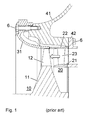
- Fig. 1 shows a section through the axis of an axial turbine of a turbocharger according to the prior art.
- the turbine wheel 10 rotatably mounted in a housing includes a hub 11 and a plurality of blades 12 disposed thereon.
- the exhaust flow needed to drive the turbine is transmitted through a flow channel from the gas inlet housing 42 via the nozzle ring 20 to the blades of the turbine wheel and further through the diffuser 31 led to the gas outlet housing 41.
- the nozzle ring 20 includes an inner wall 21 and an outer wall 22 and vanes 23 disposed therebetween.
- the walls of the nozzle ring as well as the diffuser are housing parts which define the flow channel of the exhaust gas.
- the flow channel in the region of the rotor blades is delimited by a cover ring radially enclosing the rotor blades.
- This housing part can, as in the Fig. 1 , be formed as an integral part of the downstream of the blades arranged diffuser 31.
- the cover ring may be formed as an integral part of the radially outer housing wall 22 of the nozzle ring or as an independent component.
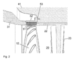
- Fig. 2 shows a section through the axis of an axial turbine of an exhaust gas turbocharger with a trained according to the invention as a brush cover ring, which the Flow channel in the region radially outside the blades 12 of the turbine wheel limited.
- the present invention designed as a brush cover ring consists of a circumferential outer ring 52, which can be positively or non-positively, for example, as shown by means of fasteners 53, attached to the housing 41.
- the ring 52 carries against radially inner a plurality of bristles 51, which close together give a flexible cover of the flow channel.
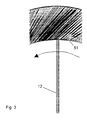
- the bristles 51 may be strictly radially aligned or, unlike the radial direction, may be inclined in the direction of the rotating blades, as shown schematically in FIG Fig. 3 is indicated.
- the support ring 52 and the bristles 51 of the brush are advantageously made of metal.
- the bristles can, as in the execution according to Fig. 4 be formed as a thin, untwisted individual wires. Alternatively, as in the embodiment according to Fig. 5 , in each case several individual wires are twisted into a strand per bristle.
- the individual bristles can be of the same length or different lengths.
- the bristles can also be of different lengths in the axial direction of the brush, that is, in the flow direction of the exhaust gas through the flow channel of the turbines. Any excess lengths can be ground away from the blade tips in a grinding process.
- the inventive exhaust gas turbine can be used instead of driving a compressor as a power turbine, about to drive an electric generator or a mechanical machine.
Landscapes
- Engineering & Computer Science (AREA)
- General Engineering & Computer Science (AREA)
- Mechanical Engineering (AREA)
- Supercharger (AREA)
Abstract
Description
Die Erfindung bezieht sich auf das Gebiet der Abgasturbolader für aufgeladene Brennkraftmaschinen.The invention relates to the field of exhaust gas turbochargers for supercharged internal combustion engines.
Sie betrifft die Abgasturbine eines Abgasturboladers, wobei die Abgasturbine ein Turbinenrad mit Laufschaufeln und einen die Laufschaufeln radial umgebenden Abdeckring umfasst.It relates to the exhaust gas turbine of an exhaust gas turbocharger, wherein the exhaust gas turbine comprises a turbine wheel with blades and a cover ring radially surrounding the blades.
Abgasturbolader werden zur Leistungssteigerung von Brennkraftmaschinen, insbesondere Hubkolbenmotoren, eingesetzt. Dabei besitzt ein Abgasturbolader üblicherweise einen Radialverdichter und eine Radial- oder Axialturbine. Ab einer bestimmten Grösse ist es sinnvoll Axialturbinen für den Antrieb des Verdichters einzusetzen. Damit das Abgas die Laufschaufeln der Axialturbine nicht umgehen kann, werden diese von einem Gehäuseteil radial aussen umschlossen. Dieses Gehäuseteil begrenzt somit im Bereich der Laufschaufeln den Strömungskanal radial nach Aussen. Dieses Gehäuseteil, allgemein als Abdeckring bezeichnet, kann als integraler Bestandteil eines stromab der Laufschaufeln angeordneten Diffusors, als integraler Bestandteil einer radial äusseren Gehäusewand eines stromauf der Laufschaufeln angeordneten Düsenrings oder als separates Bauteil ausgebildet sein.Exhaust gas turbochargers are used to increase the performance of internal combustion engines, in particular reciprocating engines. In this case, an exhaust gas turbocharger usually has a centrifugal compressor and a radial or axial turbine. From a certain size it makes sense to use axial turbines for the drive of the compressor. So that the exhaust gas can not bypass the blades of the axial turbine, they are surrounded by a housing part radially outward. This housing part thus limits the flow channel radially outward in the region of the rotor blades. This housing part, generally referred to as cover ring, can be formed as an integral part of a diffuser arranged downstream of the rotor blades, as an integral component of a radially outer housing wall of a nozzle ring arranged upstream of the rotor blades, or as a separate component.
Je nach verwendetem Treibstoff, vor allem bei Schweröl (Heavy Fuel Oil, HFO), ist das Abgas stark mit Russ, Asche und anderen Schadstoffen verschmutzt. Diese lagern sich mit der Zeit auf gewissen Bauteilen der Abgasturbine, insbesondere auf den Laufschaufeln, dem Abdeckring, den Leitschaufeln des Düsenrings sowie dem Diffusor, ab und mindern den Wirkungsgrad der Abgasturbine, was insgesamt die Leistung der Brennkraftmaschine reduziert. Aus diesem Grund müssen die verschmutzten Bauteile der Abgasturbine in regelmässigen Abständen gereinigt werden. Üblicherweise wird die Abgasturbine mit Wasser gewaschen. Um die Belastungen für die verschmutzten Bauteil gering zu halten, wird von Turboladerherstellern vorgeschrieben, die Last der Brennkraftmaschine während des Waschvorgangs zu reduzieren. Dadurch wird die Temperatur der betroffenen Bauteile schon vor dem Waschvorgang etwas reduziert was zu kleineren Belastungen führt.Depending on the fuel used, especially in heavy fuel oil (HFO), the exhaust gas is heavily contaminated with soot, ash and other pollutants. These are deposited over time on certain components of the exhaust gas turbine, in particular on the blades, the cover, the guide vanes of the nozzle ring and the diffuser, and reduce the efficiency of the exhaust gas turbine, which reduces the overall performance of the internal combustion engine. For this reason, the soiled components of the exhaust gas turbine must be cleaned at regular intervals. Usually, the Exhaust gas turbine washed with water. In order to minimize the burden on the contaminated components, turbocharger manufacturers dictate that the load on the internal combustion engine be reduced during the wash cycle. As a result, the temperature of the affected components is already slightly reduced before the washing process, resulting in smaller loads.
Da die Betreiber der Brennkraftmaschinen in der Regel nicht gerillt sind die Last der Brennkraftmaschine während des Reinigungsvorgangs zu reduzieren, triff das kühle Wasser auf die sehr heissen Bauteile. Da das Turbinenrad eine massive Scheibe jedoch der Abdeckring im Vergleich dazu nur ein dünnes Rohr ist, kühlt der Abdeckring viel schneller ab als das Turbinenrad. Das führt dazu, dass sich dieser schneller in radialer Richtung zusammenzieht. Aufgrund der engen Toleranzen zwischen den radial äussersten Spitzen der Laufschaufeln des Turbinenrades und dem angrenzenden Abdeckring kommt es deshalb häufig vor, dass die Laufschaufeln des Turbinenrades während des Waschvorgangs am Abdeckring streifen. Dies führt zu Abnutzung sowohl am Abdeckring als auch an den Spitzen der Laufschaufeln, was wiederum den Wirkungsgrad der Turbine mindert und insgesamt die Leistung der Brennkraftmaschine reduziert.Since the operators of the internal combustion engines are usually not grooved to reduce the load of the internal combustion engine during the cleaning process, meet the cool water on the very hot components. Since the turbine wheel is a massive disk, however, the cover ring is only a thin tube compared to that, the cover ring cools much faster than the turbine wheel. This causes it to contract faster in the radial direction. Because of the tight tolerances between the radially outermost tips of the blades of the turbine wheel and the adjacent cover ring, it is therefore often the case that the blades of the turbine wheel during the washing process on the cover ring. This leads to wear both on the cover ring and on the tips of the blades, which in turn reduces the efficiency of the turbine and overall reduces the performance of the internal combustion engine.
Die
Die
Eine andere Möglichkeit zum Schutz der Laufschaufelspitzen bei Verunreinigungen besteht gemäss
Obwohl die vorgeschlagenen Lösungen teilweise ansprechende Wirkung zeigen, gibt es für unter Volllast zu reinigende Abgasturbinen weiterhin Verbesserungspotential.Although the proposed solutions show partially appealing effect, there is still room for improvement for exhaust gas turbines to be cleaned under full load.
In diesem Sinne besteht die Aufgabe der vorliegenden Erfindung darin, eine Abgasturbine eines Abgasturboladers weiter zu verbessern, damit sie Reinigungsvorgängen unter Volllast ohne Abnutzungserscheinungen an den Bauteilen der Abgasturbine standhält.In this sense, the object of the present invention is to further improve an exhaust gas turbine of an exhaust gas turbocharger, so that it withstands cleaning operations under full load without signs of wear on the components of the exhaust gas turbine.
Dies wird erfindungsgemäss erreicht, indem der Abdeckring radial ausserhalb der Laufschaufeln des Turbinenrades als Bürste mit einem Tragring und einer Vielzahl von freistehenden Borsten ausgebildet ist.This is achieved according to the invention by the cover ring is formed radially outside the blades of the turbine wheel as a brush with a support ring and a plurality of free-standing bristles.
Die Bürste ist vorteilhafterweise aus Metall gefertigt. Die Borsten können als Einzeldrähte - pro Borste jeweils ein dünnes, langes, biegsames Stück Metall mit kreisförmigem, flachem, vierkantigem oder anders profiliertem Querschnitt - oder aber als verdrillte Litzen - pro Borste jeweils mehrere Einzeldrähte verdrillt - gefertigt sein.The brush is advantageously made of metal. The bristles can be manufactured as individual wires - per bristle in each case a thin, long, bendable piece of metal with a circular, flat, square or otherwise profiled cross section - or as twisted strands - each strand is twisted several individual wires per bristle.
Die Bürste als Abdeckring hat den Vorteil, dass bei einer Berührung zwischen den Schaufelspitzen und den Borsten es zu keiner Materialabtragung am Abdeckring oder an den Laufschaufeln kommt, da sich die Borsten in Laufrichtung der Laufschaufeln biegen können.The brush as a cover ring has the advantage that in a contact between the blade tips and the bristles there is no material removal on the cover ring or on the blades, as the bristles can bend in the running direction of the blades.
Dies ist insbesondere auch beim Reinigungsvorgang unter Volllast von Vorteil, da ein ungleichmässiges Verziehen des Bürsten-Abdeckrings nicht zu gefährlichen Berührungen zwischen den schnell rotierenden Laufschaufelspitzen und feststehenden Gehäuseteilen führt.This is particularly advantageous during the cleaning process under full load, as an uneven distortion of the brush cover ring does not lead to dangerous contact between the rapidly rotating blade tips and stationary housing parts.
Optional können die Borsten in radialer Richtung oder in Abweichung zur radialen Richtung leicht in Drehrichtung der Laufschaufeln geneigt ausgerichtet sein.Optionally, the bristles may be slightly inclined in the radial direction or deviating from the radial direction in the direction of rotation of the blades.
Weitere Vorteile ergeben sich aus den abhängigen Ansprüchen.Further advantages emerge from the dependent claims.
Folgend sind anhand der Zeichnungen Ausführungsformen des Abgasturboladers mit erfindungsgemäss ausgeführten Turbinenabdeckringen beschrieben. Hierbei zeigt
- Fig. 1
- ein Schnittbild einer Abgasturbine gemäss dem Stand der Technik, mit einem im Diffusor integrierten Abdeckring über den Laufschaufeln der Turbine,
- Fig. 2
- ein Schnittbild einer Abgasturbine mit einem erfindungsgemäss als Bürste ausgebildeten Abdeckring,
- Fig. 3
- eine schematische Darstellung eines Schnittes senkrecht zur Turbinenachse mit schräg zur radialen Richtung ausgerichteten Borsten der Bürste,
- Fig. 4
- eine schematische Darstellung eines Schnitts durch die Bürste mit einer ersten Ausführungsform der Borsten der Bürste, und
- Fig. 5
- eine schematische Darstellung eines Schnitts durch die Bürste mit einer zweiten Ausführungsform der Borsten der Bürste.
- Fig. 1
- a sectional view of an exhaust gas turbine according to the prior art, with a built-in diffuser cover over the blades of the turbine,
- Fig. 2
- a sectional view of an exhaust gas turbine with a present invention designed as a brush cover ring,
- Fig. 3
- 1 is a schematic representation of a section perpendicular to the turbine axis with bristles of the brush oriented obliquely to the radial direction,
- Fig. 4
- a schematic representation of a section through the brush with a first embodiment of the bristles of the brush, and
- Fig. 5
- a schematic representation of a section through the brush with a second embodiment of the bristles of the brush.
Damit das Abgas den Laufschaufeln des Turbinenrades nicht ausweichen kann, wird der Strömungskanal im Bereich der Laufschaufeln von einem die Laufschaufeln radial umschliessenden Abdeckring begrenzt. Dieses Gehäuseteil kann, wie in der
Der erfindungsgemäss als Bürste ausgebildete Abdeckring besteht aus einem umlaufenden äusseren Ring 52, welcher form- oder kraftschlüssig, beispielsweise wie dargestellt mittels Befestigungsmitteln 53, am Gehäuse 41 befestigt sein kann. Der Ring 52 trägt gegen radial Innen eine Vielzahl von Borsten 51, welche eng zusammengefügt eine flexible Abdeckung des Strömungskanals ergeben. Die Borsten 51 können streng radial ausgerichtet sein oder aber in Abweichung zur radialen Richtung mit einer Neigung in die Richtung der rotierenden Laufschaufeln versehen sein, wie dies schematisch in
Der Tragring 52 sowie die Borsten 51 der Bürste sind vorteilhafterweise aus Metall gefertigt. Die Borsten können, wie in der Ausführung nach
Die einzelnen Borsten können gleich lang oder unterschiedlich lang ausgebildet sein. Insbesondere können die Borsten auch in axialer Richtung der Bürste, also in Strömungsrichtung des Abgases durch den Strömungskanal der Turbinen unterschiedlich lang ausgebildet sein. Allfällige Überlängen können von den Schaufelspitzen in einem Einschleifprozess abgeschliffen werden.The individual bristles can be of the same length or different lengths. In particular, the bristles can also be of different lengths in the axial direction of the brush, that is, in the flow direction of the exhaust gas through the flow channel of the turbines. Any excess lengths can be ground away from the blade tips in a grinding process.
Die erfindungsgemässe Abgasturbine kann anstatt zum Antreiben eines Verdichters auch als Nutzturbine eingesetzt werden, etwa um einen Elektro-Generator oder eine mechanische Maschine anzutreiben.The inventive exhaust gas turbine can be used instead of driving a compressor as a power turbine, about to drive an electric generator or a mechanical machine.
- 1010
- Turbinenradturbine
- 1111
- Turbinenradnabeturbine hub
- 1212
- Laufschaufeln des TurbinenradesBlades of the turbine wheel
- 2020
- Düsenringnozzle ring
- 2121
- Innenwand des DüsenringsInner wall of the nozzle ring
- 2222
- Aussenwand des DüsenringsOuter wall of the nozzle ring
- 2323
- Leitschaufeln des DüsenringsGuide vanes of the nozzle ring
- 3131
- Diffusordiffuser
- 4141
- GasaustrittsgehäuseGas outlet casing
- 4242
- GaseintrittsgehäuseGas inlet casing
- 5151
- Borsten der BürsteBristles of the brush
- 5252
- Tragring der BürsteCarrying ring of the brush
- 5353
- Befestigungsmittelfastener
- 66
- Befestigungsmittelfastener
Claims (7)
Priority Applications (1)
| Application Number | Priority Date | Filing Date | Title |
|---|---|---|---|
| EP09150103A EP2204548A1 (en) | 2009-01-06 | 2009-01-06 | Exhaust gas turbine with shroud and corresponding exhaust turbocharger |
Applications Claiming Priority (1)
| Application Number | Priority Date | Filing Date | Title |
|---|---|---|---|
| EP09150103A EP2204548A1 (en) | 2009-01-06 | 2009-01-06 | Exhaust gas turbine with shroud and corresponding exhaust turbocharger |
Publications (1)
| Publication Number | Publication Date |
|---|---|
| EP2204548A1 true EP2204548A1 (en) | 2010-07-07 |
Family
ID=40668109
Family Applications (1)
| Application Number | Title | Priority Date | Filing Date |
|---|---|---|---|
| EP09150103A Withdrawn EP2204548A1 (en) | 2009-01-06 | 2009-01-06 | Exhaust gas turbine with shroud and corresponding exhaust turbocharger |
Country Status (1)
| Country | Link |
|---|---|
| EP (1) | EP2204548A1 (en) |
Cited By (1)
| Publication number | Priority date | Publication date | Assignee | Title |
|---|---|---|---|---|
| EP2853783A1 (en) * | 2013-09-20 | 2015-04-01 | MTU Aero Engines GmbH | Brush seal and method of forming a brush seal |
Citations (11)
| Publication number | Priority date | Publication date | Assignee | Title |
|---|---|---|---|---|
| CH351142A (en) | 1955-08-18 | 1960-12-31 | Bmw Triebwerkbau Ges Mit Besch | Fixed cover ring with sealing elements around the impeller blade ends of a gas turbine |
| GB2139293A (en) * | 1983-05-06 | 1984-11-07 | Mtu Muenchen Gmbh | Abradable coating for a turbo compressor stutor/rotor assembly |
| JPH0441901A (en) * | 1990-06-01 | 1992-02-12 | Hitachi Ltd | Structure for turbine rotor blade |
| DE4432685C1 (en) * | 1994-09-14 | 1995-11-23 | Mtu Muenchen Gmbh | Starting cover for turbo=machine casing |
| US20020081195A1 (en) * | 2000-12-21 | 2002-06-27 | Wolfe Christopher Edward | Bucket tip brush seals in steam tubines and methods of installation |
| EP1270876A2 (en) * | 2001-06-18 | 2003-01-02 | General Electric Company | Spring-backed abradable seal for turbomachinery |
| US20050006851A1 (en) * | 2003-07-09 | 2005-01-13 | Addis Mark E. | Brush seal with windage control |
| DE102004038933A1 (en) * | 2004-08-11 | 2006-02-23 | Mtu Aero Engines Gmbh | sealing arrangement |
| US20070187900A1 (en) * | 2004-05-04 | 2007-08-16 | Advanced Components & Materials, Inc. | Non-metallic brush seals |
| EP1820938A1 (en) | 2006-02-20 | 2007-08-22 | ABB Turbo Systems AG | Cleaning elements on blade tips of an exhaust turbine |
| EP1895107A1 (en) | 2006-08-29 | 2008-03-05 | ABB Turbo Systems AG | Exhaust gas turbine with segmented shroud ring |
-
2009
- 2009-01-06 EP EP09150103A patent/EP2204548A1/en not_active Withdrawn
Patent Citations (11)
| Publication number | Priority date | Publication date | Assignee | Title |
|---|---|---|---|---|
| CH351142A (en) | 1955-08-18 | 1960-12-31 | Bmw Triebwerkbau Ges Mit Besch | Fixed cover ring with sealing elements around the impeller blade ends of a gas turbine |
| GB2139293A (en) * | 1983-05-06 | 1984-11-07 | Mtu Muenchen Gmbh | Abradable coating for a turbo compressor stutor/rotor assembly |
| JPH0441901A (en) * | 1990-06-01 | 1992-02-12 | Hitachi Ltd | Structure for turbine rotor blade |
| DE4432685C1 (en) * | 1994-09-14 | 1995-11-23 | Mtu Muenchen Gmbh | Starting cover for turbo=machine casing |
| US20020081195A1 (en) * | 2000-12-21 | 2002-06-27 | Wolfe Christopher Edward | Bucket tip brush seals in steam tubines and methods of installation |
| EP1270876A2 (en) * | 2001-06-18 | 2003-01-02 | General Electric Company | Spring-backed abradable seal for turbomachinery |
| US20050006851A1 (en) * | 2003-07-09 | 2005-01-13 | Addis Mark E. | Brush seal with windage control |
| US20070187900A1 (en) * | 2004-05-04 | 2007-08-16 | Advanced Components & Materials, Inc. | Non-metallic brush seals |
| DE102004038933A1 (en) * | 2004-08-11 | 2006-02-23 | Mtu Aero Engines Gmbh | sealing arrangement |
| EP1820938A1 (en) | 2006-02-20 | 2007-08-22 | ABB Turbo Systems AG | Cleaning elements on blade tips of an exhaust turbine |
| EP1895107A1 (en) | 2006-08-29 | 2008-03-05 | ABB Turbo Systems AG | Exhaust gas turbine with segmented shroud ring |
Cited By (2)
| Publication number | Priority date | Publication date | Assignee | Title |
|---|---|---|---|---|
| EP2853783A1 (en) * | 2013-09-20 | 2015-04-01 | MTU Aero Engines GmbH | Brush seal and method of forming a brush seal |
| US10100655B2 (en) | 2013-09-20 | 2018-10-16 | MTU Aero Engines AG | Brush seal and method for producing a brush seal |
Similar Documents
| Publication | Publication Date | Title |
|---|---|---|
| EP2179143B1 (en) | Gap cooling between combustion chamber wall and turbine wall of a gas turbine installation | |
| EP2824282A1 (en) | Gas turbine with high pressure turbine cooling system | |
| EP2194277A1 (en) | Compressor stabiliser | |
| DE2257793A1 (en) | COMPRESSOR FOR CHARGING A COMBUSTION ENGINE | |
| EP3682092B1 (en) | Exhaust gas turbine with a diffusser | |
| EP2101040A2 (en) | Turbomachine with multi-flow rotor assembly | |
| DE10028733A1 (en) | Exhaust turbine for turbocharger ha guide blades with flow intake edges and/or outflow edges at angle relative to jacket line, and cover rings to connected blade ends | |
| EP2781699B1 (en) | Cleaning device of an exhaust gas turbine | |
| EP2112332B1 (en) | Supporting ring for a guide vane assembly with an air-sealed channel | |
| EP2218918A1 (en) | Axial turbo compressor for a gas turbine with low blade-tip leakage losses and diffuser losses | |
| EP2821596A1 (en) | Air intake a compressor of an exhaust gas turbocharger | |
| EP3164578B1 (en) | Discharge region of a turbocharger turbine | |
| EP1895107A1 (en) | Exhaust gas turbine with segmented shroud ring | |
| EP2204548A1 (en) | Exhaust gas turbine with shroud and corresponding exhaust turbocharger | |
| EP2725203A1 (en) | Cool air guide in a housing structure of a fluid flow engine | |
| EP1673519B1 (en) | Sealing arrangement for a gas turbine | |
| DE102015215207A1 (en) | Combustion chamber for a gas turbine and heat shield element for lining such a combustion chamber | |
| DE102022121076A1 (en) | METHOD OF REDUCING HIGH CYCLE FATIGUE OF TURBINE WHEELS IN SPLIT SECTOR DOUBLE SCROLL CASE TURBOCHARGER | |
| DE102013220455A1 (en) | Gas turbine engine with cooling air ring chamber | |
| DE102014226341A1 (en) | Compressor, exhaust gas turbocharger and internal combustion engine | |
| DE102011051477A1 (en) | Method and device for assembling rotary machines | |
| DE102011107557A1 (en) | Flow pump for use as centrifugal pump in automotive industry, has housing and pump wheel that is rotationally driven within pump chamber of housing, where one or more guide vanes are rotated not with pump wheel | |
| EP2687684A1 (en) | Abradable coating with spiral grooves in a turbomachine | |
| DE2230718C3 (en) | ||
| EP2572108B1 (en) | Centrifugal compressor |
Legal Events
| Date | Code | Title | Description |
|---|---|---|---|
| PUAI | Public reference made under article 153(3) epc to a published international application that has entered the european phase |
Free format text: ORIGINAL CODE: 0009012 |
|
| AK | Designated contracting states |
Kind code of ref document: A1 Designated state(s): AT BE BG CH CY CZ DE DK EE ES FI FR GB GR HR HU IE IS IT LI LT LU LV MC MK MT NL NO PL PT RO SE SI SK TR |
|
| AX | Request for extension of the european patent |
Extension state: AL BA RS |
|
| AKY | No designation fees paid | ||
| REG | Reference to a national code |
Ref country code: DE Ref legal event code: R108 Effective date: 20110215 Ref country code: DE Ref legal event code: 8566 |
|
| STAA | Information on the status of an ep patent application or granted ep patent |
Free format text: STATUS: THE APPLICATION IS DEEMED TO BE WITHDRAWN |
|
| 18D | Application deemed to be withdrawn |
Effective date: 20110108 |