EP1270876A2 - Spring-backed abradable seal for turbomachinery - Google Patents
Spring-backed abradable seal for turbomachinery Download PDFInfo
- Publication number
- EP1270876A2 EP1270876A2 EP02254256A EP02254256A EP1270876A2 EP 1270876 A2 EP1270876 A2 EP 1270876A2 EP 02254256 A EP02254256 A EP 02254256A EP 02254256 A EP02254256 A EP 02254256A EP 1270876 A2 EP1270876 A2 EP 1270876A2
- Authority
- EP
- European Patent Office
- Prior art keywords
- seal
- turbine
- seal carrier
- arcuate
- spring
- Prior art date
- Legal status (The legal status is an assumption and is not a legal conclusion. Google has not performed a legal analysis and makes no representation as to the accuracy of the status listed.)
- Withdrawn
Links
Images


Classifications
-
- F—MECHANICAL ENGINEERING; LIGHTING; HEATING; WEAPONS; BLASTING
- F02—COMBUSTION ENGINES; HOT-GAS OR COMBUSTION-PRODUCT ENGINE PLANTS
- F02C—GAS-TURBINE PLANTS; AIR INTAKES FOR JET-PROPULSION PLANTS; CONTROLLING FUEL SUPPLY IN AIR-BREATHING JET-PROPULSION PLANTS
- F02C7/00—Features, components parts, details or accessories, not provided for in, or of interest apart form groups F02C1/00 - F02C6/00; Air intakes for jet-propulsion plants
- F02C7/28—Arrangement of seals
-
- F—MECHANICAL ENGINEERING; LIGHTING; HEATING; WEAPONS; BLASTING
- F01—MACHINES OR ENGINES IN GENERAL; ENGINE PLANTS IN GENERAL; STEAM ENGINES
- F01D—NON-POSITIVE DISPLACEMENT MACHINES OR ENGINES, e.g. STEAM TURBINES
- F01D11/00—Preventing or minimising internal leakage of working-fluid, e.g. between stages
- F01D11/08—Preventing or minimising internal leakage of working-fluid, e.g. between stages for sealing space between rotor blade tips and stator
- F01D11/12—Preventing or minimising internal leakage of working-fluid, e.g. between stages for sealing space between rotor blade tips and stator using a rubstrip, e.g. erodible. deformable or resiliently-biased part
- F01D11/122—Preventing or minimising internal leakage of working-fluid, e.g. between stages for sealing space between rotor blade tips and stator using a rubstrip, e.g. erodible. deformable or resiliently-biased part with erodable or abradable material
-
- F—MECHANICAL ENGINEERING; LIGHTING; HEATING; WEAPONS; BLASTING
- F16—ENGINEERING ELEMENTS AND UNITS; GENERAL MEASURES FOR PRODUCING AND MAINTAINING EFFECTIVE FUNCTIONING OF MACHINES OR INSTALLATIONS; THERMAL INSULATION IN GENERAL
- F16J—PISTONS; CYLINDERS; SEALINGS
- F16J15/00—Sealings
- F16J15/16—Sealings between relatively-moving surfaces
- F16J15/32—Sealings between relatively-moving surfaces with elastic sealings, e.g. O-rings
- F16J15/3284—Sealings between relatively-moving surfaces with elastic sealings, e.g. O-rings characterised by their structure; Selection of materials
- F16J15/3288—Filamentary structures, e.g. brush seals
-
- F—MECHANICAL ENGINEERING; LIGHTING; HEATING; WEAPONS; BLASTING
- F16—ENGINEERING ELEMENTS AND UNITS; GENERAL MEASURES FOR PRODUCING AND MAINTAINING EFFECTIVE FUNCTIONING OF MACHINES OR INSTALLATIONS; THERMAL INSULATION IN GENERAL
- F16J—PISTONS; CYLINDERS; SEALINGS
- F16J15/00—Sealings
- F16J15/44—Free-space packings
- F16J15/445—Free-space packings with means for adjusting the clearance
-
- F—MECHANICAL ENGINEERING; LIGHTING; HEATING; WEAPONS; BLASTING
- F05—INDEXING SCHEMES RELATING TO ENGINES OR PUMPS IN VARIOUS SUBCLASSES OF CLASSES F01-F04
- F05C—INDEXING SCHEME RELATING TO MATERIALS, MATERIAL PROPERTIES OR MATERIAL CHARACTERISTICS FOR MACHINES, ENGINES OR PUMPS OTHER THAN NON-POSITIVE-DISPLACEMENT MACHINES OR ENGINES
- F05C2201/00—Metals
- F05C2201/04—Heavy metals
- F05C2201/0433—Iron group; Ferrous alloys, e.g. steel
- F05C2201/0466—Nickel
-
- F—MECHANICAL ENGINEERING; LIGHTING; HEATING; WEAPONS; BLASTING
- F05—INDEXING SCHEMES RELATING TO ENGINES OR PUMPS IN VARIOUS SUBCLASSES OF CLASSES F01-F04
- F05D—INDEXING SCHEME FOR ASPECTS RELATING TO NON-POSITIVE-DISPLACEMENT MACHINES OR ENGINES, GAS-TURBINES OR JET-PROPULSION PLANTS
- F05D2240/00—Components
- F05D2240/55—Seals
- F05D2240/56—Brush seals
-
- F—MECHANICAL ENGINEERING; LIGHTING; HEATING; WEAPONS; BLASTING
- F05—INDEXING SCHEMES RELATING TO ENGINES OR PUMPS IN VARIOUS SUBCLASSES OF CLASSES F01-F04
- F05D—INDEXING SCHEME FOR ASPECTS RELATING TO NON-POSITIVE-DISPLACEMENT MACHINES OR ENGINES, GAS-TURBINES OR JET-PROPULSION PLANTS
- F05D2260/00—Function
- F05D2260/30—Retaining components in desired mutual position
-
- F—MECHANICAL ENGINEERING; LIGHTING; HEATING; WEAPONS; BLASTING
- F05—INDEXING SCHEMES RELATING TO ENGINES OR PUMPS IN VARIOUS SUBCLASSES OF CLASSES F01-F04
- F05D—INDEXING SCHEME FOR ASPECTS RELATING TO NON-POSITIVE-DISPLACEMENT MACHINES OR ENGINES, GAS-TURBINES OR JET-PROPULSION PLANTS
- F05D2300/00—Materials; Properties thereof
- F05D2300/20—Oxide or non-oxide ceramics
- F05D2300/22—Non-oxide ceramics
- F05D2300/224—Carbon, e.g. graphite
-
- F—MECHANICAL ENGINEERING; LIGHTING; HEATING; WEAPONS; BLASTING
- F05—INDEXING SCHEMES RELATING TO ENGINES OR PUMPS IN VARIOUS SUBCLASSES OF CLASSES F01-F04
- F05D—INDEXING SCHEME FOR ASPECTS RELATING TO NON-POSITIVE-DISPLACEMENT MACHINES OR ENGINES, GAS-TURBINES OR JET-PROPULSION PLANTS
- F05D2300/00—Materials; Properties thereof
- F05D2300/40—Organic materials
- F05D2300/43—Synthetic polymers, e.g. plastics; Rubber
- F05D2300/434—Polyimides, e.g. AURUM
-
- F—MECHANICAL ENGINEERING; LIGHTING; HEATING; WEAPONS; BLASTING
- F05—INDEXING SCHEMES RELATING TO ENGINES OR PUMPS IN VARIOUS SUBCLASSES OF CLASSES F01-F04
- F05D—INDEXING SCHEME FOR ASPECTS RELATING TO NON-POSITIVE-DISPLACEMENT MACHINES OR ENGINES, GAS-TURBINES OR JET-PROPULSION PLANTS
- F05D2300/00—Materials; Properties thereof
- F05D2300/40—Organic materials
- F05D2300/44—Resins
-
- F—MECHANICAL ENGINEERING; LIGHTING; HEATING; WEAPONS; BLASTING
- F05—INDEXING SCHEMES RELATING TO ENGINES OR PUMPS IN VARIOUS SUBCLASSES OF CLASSES F01-F04
- F05D—INDEXING SCHEME FOR ASPECTS RELATING TO NON-POSITIVE-DISPLACEMENT MACHINES OR ENGINES, GAS-TURBINES OR JET-PROPULSION PLANTS
- F05D2300/00—Materials; Properties thereof
- F05D2300/60—Properties or characteristics given to material by treatment or manufacturing
- F05D2300/614—Fibres or filaments
-
- F—MECHANICAL ENGINEERING; LIGHTING; HEATING; WEAPONS; BLASTING
- F05—INDEXING SCHEMES RELATING TO ENGINES OR PUMPS IN VARIOUS SUBCLASSES OF CLASSES F01-F04
- F05D—INDEXING SCHEME FOR ASPECTS RELATING TO NON-POSITIVE-DISPLACEMENT MACHINES OR ENGINES, GAS-TURBINES OR JET-PROPULSION PLANTS
- F05D2300/00—Materials; Properties thereof
- F05D2300/70—Treatment or modification of materials
- F05D2300/702—Reinforcement
Definitions
- Rotary machines include, without limitation, turbines for steam turbines and compressors and turbines for gas turbines.
- a steam turbine has a steam path that typically includes, in serial-flow relationship, a steam inlet, a turbine, and a steam outlet.
- a gas turbine has a gas path which typically includes, in serial-flow relationship, an air intake (or inlet), a compressor, a combustor, a turbine, and a gas outlet (or exhaust nozzle). Gas or steam leakage, either out of the gas or steam path or into the gas or steam path, from an area of higher pressure to an area of lower pressure, is generally undesirable.
Abstract
Description
- The present invention relates generally to rotary machines, and more particularly to a seal assembly for a rotary machine such as steam and gas turbines.
- Rotary machines include, without limitation, turbines for steam turbines and compressors and turbines for gas turbines. A steam turbine has a steam path that typically includes, in serial-flow relationship, a steam inlet, a turbine, and a steam outlet. A gas turbine has a gas path which typically includes, in serial-flow relationship, an air intake (or inlet), a compressor, a combustor, a turbine, and a gas outlet (or exhaust nozzle). Gas or steam leakage, either out of the gas or steam path or into the gas or steam path, from an area of higher pressure to an area of lower pressure, is generally undesirable. For example, a gas path leakage in the turbine or compressor area of a gas turbine, between the rotor of the turbine or compressor and the circumferentially surrounding turbine or compressor casing, will lower the efficiency of the gas turbine leading to increased fuel costs. Also, steam-path leakage in the turbine area of a steam turbine, between the rotor of the turbine and the circumferentially surrounding casing, will lower the efficiency of the steam turbine leading to increased fuel costs.
- It is known in the art of steam turbines to position, singly or a combination, variable clearance labyrinth-seal segments and brush seals in a circumferential array between the rotor of the turbine and the circumferentially surrounding casing to minimize steam-path leakage. Springs hold the segments radially inward against surfaces on the casing that establish radial clearance between seal and rotor but allow segments to move radially outward in the event of rotor contact. While labyrinth seals, singly or in combination with brush seals, have proved to be quite reliable, their performance degrades over time as a result of transient events in which the stationary and rotating components interfere, rubbing the labyrinth teeth into a "mushroom" profile and opening the seal clearance.
- Accordingly, there is a need in the art for a rotary machine having good leakage control between stationary and rotating components.
- The present invention provides, in one embodiment, an annular turbine seal for disposition in a turbine between a rotatable component having an axis of rotation and a turbine housing about the same axis of rotation. The turbine seal has a plurality of arcuate seal carrier segments that have an abradable portion secured to the seal carrier segments. In addition, at least one spring is disposed on the seal carrier segment to exert a force and maintain the seal carrier segment adjacent to the rotatable component.
- These and other features, aspects, and advantages of the present invention will become better understood when the following detailed description is read with reference to the accompanying drawings in which like characters represent like parts throughout the drawings, wherein:
- FIG 1 is a schematic, cross-sectional exploded view of one embodiment of the instant invention.
- FIG 2 is a schematic, cross-sectional exploded view of another embodiment of the instant invention.
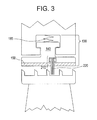
- FIG 3 is a schematic, cross-sectional exploded view of another embodiment of the instant invention.
- FIG 4 is a schematic, cross-sectional exploded view of another embodiment of the instant invention.
- FIG 5 is a schematic, cross-sectional exploded view of another embodiment of the instant invention.
-
- A
rotary machine 100, for example, a steam turbine, typically comprises a rotatingturbine bucket 110 disposed in astationary turbine housing 120 and whichturbine bucket 110 is supported by conventional means, not shown, within turbine housing 120 (as shown in Fig. 1). Anabradable seal 130, generally designated 130, disposed between rotatingturbine bucket 110 andstationary turbine housing 120, comprises an arcuateseal carrier segment 140 disposed adjacent toturbine bucket 110 separating pressure regions on axially opposite sides of arcuateseal carrier segment 140. Arcuateseal carrier segment 140 includes anabradable portion 150 radially disposed on seal carrier segmentfirst surface 190. As used herein, "on", "over", "above", "under" and the like are used to refer to the relative location of elements ofrotary machine 100 as illustrated in the Figures and is not meant to be a limitation in any manner with respect to the orientation or operation ofrotary machine 100. It will be appreciated that while only one arcuateseal carrier segment 140 and oneabradable portion 150 are illustrated, typically a plurality ofabradable seals 130 having at least oneabradable portion 150 and at least one arcuateseal carrier segment 140 are provided aboutturbine bucket 110.Abradable portion 150 is of a design for obtaining close clearances with the radial projections orribs 160 and thegrooves 170 of thebucket cover 180. For example, during operation,ribs 160 andgrooves 170 wear away part ofabradable portion 150 leaving a profile matching that ofribs 160 andgrooves 170 onabradable portion 150 resulting in a close clearance between the components. The clearance is typically in the range between about 0.02mm and about 0.7mm. It will also be appreciated by one of ordinary skill in the art that the location, number and height ofribs 160 andgrooves 170 located onbucket cover 180 may be varied. In addition,turbine bucket 110 components (e.g. bucket cover 180) facingabradable portion 150 may be varied as well, for example, there may not be abucket cover 180 and therefore theturbine bucket 110 surface may be flat. -
Abradable seal 130 segments are typically spring-backed and are thus free to move radially when subjected to movement during normal conditions of startup. For example,abradable seal 130 segments are free to move radially when there is a variance from the normal rotational profile betweenabradable seal 130 andturbine bucket 110. In one embodiment,springs 185 exert a force to keepabradable seal 130 disposed adjacent tobucket cover 180 and allow some radially outward movement of arcuateseal carrier segment 140 during transient events, for example, during startup and shutdown. Springs 185 typically comprise, but are not limited to, leaf springs or coil springs. Springs 185 apply a radial force, when assembled in the rotary machine, that is typically in the range of about 2 to about 5 times the weight of the arcuateseal carrier segment 140 that it is supporting. In operation,springs 185 only need to provide enough force to seat arcuateseal carrier segment 140 radially towardturbine housing 120 and keep arcuateseal carrier segment 140 disposed adjacent toturbine bucket 110,bucket cover 180 or blades (see Fig. 2). As a result of "seating" arcuateseal carrier segment 140 radially towardturbine housing 120, the gap "G" (see Figure 1) betweenseal carrier segment 140 andturbine housing 120 is minimized thus reducing gas or steam leakage in the turbine area of a gas or steam turbine (see Figure 2). For example, in steam turbine applications, the weight of an individual arcuateseal carrier segment 140 is typically in the range of about 10 pounds to about 25 pounds. Thus,springs 185 must provide at least this level of force in order to provide enough force to seat arcuateseal carrier segments 140 radially towardturbine housing 120. In another embodiment,spring 185 is disposed on a plurality of arcuateseal carrier segments 140. In another embodiment, a single spring is disposed on the entire annular array of arcuateseal carrier segments 140. - In another embodiment, the spring system of the present invention is adapted to be used in conjunction with other means to apply pressure to arcuate
seal carrier segments 140. For example, springs work in conjunction with gas pressures (illustrated in phantom in Fig. 2) for providing a force to keepabradable seal 130 disposed adjacent tobucket cover 180 orturbine buckets 110. In this embodiment, arcuateseal carrier segment 140 is initially pushed axially towardturbine housing 120 by the upstream pressure which is caused by the expansion of the gas through the turbine and dictated by the design of the gas or steam path geometry and flow (see FIG. 1). This upstream pressure eventually fills the cavity betweenturbine housing 120 and arcuateseal carrier segment 140 and further forces arcuateseal carrier segment 140 radially inward to reduce the clearance withturbine buckets 110, for example, after the turbine has been brought up to speed. In one embodiment, at least onespring 185 is disposed on each of the arcuateseal carrier segments 140. - In one embodiment,
abradable portion 150 composition typically comprises a first component comprising cobalt, nickel, chromium, aluminum, yttrium (hereinafter referred to as CoNiCrAlY) and a second component selected from the group consisting of hexagonal boron nitride (hexagonal BN) and a polymer. Typical polymers used are thermosets, such as polyesters and polyimides. In another embodiment,abradable portion 150 composition typically comprises a component comprising nickel, chromium and aluminum, and another component comprising clay (e.g. bentonite) (hereinafter referred to as "NiCrAI + clay"). Another embodiment is a composition typically comprising a first component consisting nickel and graphite (hereinafter referred to as "Ni + Graphite") or a second component comprising of stainless steel. Another embodiment is a composition typically comprising nickel, chromium, iron, aluminum, boron and nitrogen (hereinafter referred to as "NiCrFeAIBN"). Another embodiment comprises a first component comprising chromium, aluminum and yttrium (hereinafter referred to as "CrAIY") and a second component selected from the group consisting of iron, nickel and cobalt. Furthermore,abradable portion 150 may consist of a composition typically comprising a first component comprising chromium and aluminum (hereinafter referred to as "CrAI") and a second component selected from the group consisting of iron, nickel and cobalt. Other embodiments ofabradable portion 150 composition may include a material composed of metal fibers that are pressed or sintered together or infiltrated with resin or other material, for example, Feltmetal™ (offered for sale by Technectics Corp., DeLand, FL) and a nickel based alloy with high resistance to oxidation, for example, Hastelloy™ (offered for sale by Technectics Corp., DeLand, FL). It will be appreciated thatabradable portion 150 is disposed on seal carrier segmentfirst surface 190 by brazing or thermal spraying, for example. In addition, it will be appreciated by one of ordinary skill in the art that the thermal spray may be adjusted to introduce porosity into the abradable portion. Operating conditions forabradable portion 150 composition is typically in the range between about 20°C and about 700°C. - Referring to FIG 1,
abradable portion 150 nominally projects from arcuate seal carrier segment 140 a distance "t" which corresponds to the maximum expected radial incursion of theturbine buckets 110 or blades into theabradable portion 150 ofabradable seal carrier 130 in a radial direction. Consequently, the distance "t" corresponds to the radial deflection of theturbine buckets 110 and its calculation is dependent on the predicted deflection ofrotary machine 100 and the radial deflection of arcuateseal carrier segments 140 during transient or steady-state operation.Abradable portion 150 radial distance "t" is typically in the range between about 0.5 mm and about 5 mm. In one embodiment,abradable portion 150 arcuate length "I" and width "w" is equal to the arcuate length and width of the arcuate seal carrier segment 140 (see Fig. 5). It will be appreciated that arcuate length and width ofabradable portion 150 may vary depending upon the application. - In accordance with another embodiment of the instant invention (see FIG. 2), there is provided a springbacked
abradable seal 130 formed by the combination of anabradable portion 150 and at least onelabyrinth tooth 200. It will be appreciated that the location and number oflabyrinth teeth 200 on arcuateseal carrier segment 140 may be varied. In one embodiment,labyrinth teeth 200 are typically located at the periphery of each arcuateseal carrier segment 140 as shown in Figure 2. Here, at least onelabyrinth tooth 200 profile extends 360° about the edge annular array of seal carrier segments (not shown). In accordance with another embodiment of the instant invention (see FIG. 3), there is provided a springbackedabradable seal 130 formed by the combination of anabradable portion 150 and at least onebrush seal 210. It will be appreciated that the location and number of at least onebrush seal 210 may be varied depending upon desired application. In operation, it will be appreciated that the combinedabradable portion 150 and at least onebrush seal 210 may move radially inwardly and outwardly with the tips of thebristles 220 engaging the turbine bucket covers 180 substantially throughout the full 360° circumference of the rotor. - In accordance with another embodiment of the instant invention (see FIG. 4), there is provided a springbacked
abradable seal 130 formed by the combination of anabradable portion 150, at least onebrush seal 210 and at least onelabyrinth tooth 200. It will be appreciated that the location and number of at least onebrush seal 210 and at least onelabyrinth tooth 200 may be varied depending upon desired application. For example, in steam or gas turbines, solid particles are typically centrifuged outward at the blade tips. Thelabyrinth tooth 200 andbrush seal 210 serve as auxiliary seals in case of excessive erosion of the abradable portion. Depending upon at least onebrush seal 210 bristle angle, there may be a lack ofbristles 220 at the ends of arcuateseal carrier segment 140. The lack ofbristles 220 at the ends of arcuateseal carrier segment 140 does seriously compromise or degrade the sealing capability because of the structural combination withabradable portion 150, at least onelabyrinth tooth 200 or both. - For completeness various aspects of the invention are set out in the following numbered clauses:
- 1. An annular turbine seal for disposition in a turbine between a rotatable
component having an axis of rotation and a
turbine housing 120 about said axis, comprising: - a plurality of arcuate
seal carrier segments 140, each of saidseal carrier segments 140 comprising anabradable portion 150 wherein saidabradable portion 150 is secured to each of said arcuateseal carrier segments 140; and - at least one
spring 185 disposed so as to exert a force to maintain said arcuateseal carrier segments 140 disposed adjacent to said rotatable component during rotation. - 2. The annular turbine seal of clause 1, wherein said
abradable portion 150 has an operating temperature in the range between about 20°C and about 700°C. - 3. The annular turbine seal of clause 1, wherein said arcuate
seal carrier segment 140 comprises at least onelabyrinth tooth 200. - 4. The annular turbine seal of clause 3, wherein said
labyrinth tooth 200 is disposed at the outer periphery of said arcuateseal carrier segment 140. - 5. The annular turbine seal of clause 1, wherein said arcuate
seal carrier segment 140 comprises at least onebrush seal 210. - 6. The annular turbine seal of clause 1, wherein said arcuate
seal carrier segment 140 further comprises at least onebrush seal 210 and at least onelabyrinth tooth 200 combined with said at least oneabradable portion 150. - 7. The annular turbine seal of clause 1, wherein said at least one
abradable portion 150 has a radial distance in the range between about 0.5 mm and about 5 mm. - 8. The annular turbine seal of clause 1, wherein said at least one
abradable portion 150 has a width equal to said arcuateseal carrier segment 140 width. - 9. The annular turbine seal of clause 1, wherein said at least one
abradable portion 150 has an arcuate length equal to said arcuateseal carrier segment 140 length. - 10. The annular turbine seal of clause 1, wherein said
spring 185 comprises a leaf spring. - 11. The annular turbine seal of clause 1, wherein said
spring 185 comprises a coil spring. - 12. The annular turbine seal of clause 1, wherein said
respective spring 185 is disposed on each of said arcuateseal carrier segments 140. - 13. The annular turbine seal of clause 1, wherein said
respective spring 185 is disposed on a plurality of said arcuateseal carrier segments 140. - 14. The annular turbine seal of clause 1, wherein said
respective spring 185 is disposed on an entirety of said arcuateseal carrier segments 140. - 15. The annular turbine seal of clause 1, wherein said
abradable portion 150 comprises CoNiCrAlY and further comprises material selected from the group consisting of hexagonal BN, thermoset polymer and mixtures thereof. - 16. The annular turbine seal of clause 15, wherein said thermoset polymer is selected from the group consisting of a polyester and a polyimide.
- 17. The annular turbine seal of clause 1, wherein said
abradable portion 150 comprises NiCrAI and clay. - 18. The annular turbine seal of clause 17, wherein said clay comprises bentonite.
- 19. The annular turbine seal of clause 1, wherein said
abradable portion 150 comprises nickel and graphite. - 20. The rotary machine of clause 1, wherein said
abradable portion 150 comprises NiCrFeAIBN. - 21. The annular turbine seal of clause 1, wherein said
abradable portion 150 comprises stainless steel. - 22. The annular turbine seal of clause 1, wherein said
abradable portion 150 comprises chromium and aluminum and least one member of the group consisting of yttrium, iron, nickel and cobalt. - 23. The annular turbine seal of clause 1, wherein said
abradable portion 150 comprises a nickel based alloy. - 24. An
rotary machine 100 having a plurality of stages comprising: - a rotatable component;
- a fixed component surrounding said rotatable component, said components lying about a common axis; and
- a plurality of arcuate
seal carrier segments 140 disposed between said rotatable component and said fixed component, each of saidseal carrier segments 140 comprising anabradable portion 150 and at least onespring 185 disposed so as to exert a force to maintain said arcuateseal carrier segments 140 disposed adjacent to said rotatable component. - 25. The
rotary machine 100 of clause 24, wherein saidrotary machine 100 is a steam turbine. - 26. The
rotary machine 100 of clause 24, wherein saidrotary machine 100 is a gas turbine. - 27. The
rotary machine 100 of clause 24, wherein said abradable portion has an operating temperature in the range between about 20°C and about 700°C. - 28. The
rotary machine 100 of clause 24, wherein said arcuateseal carrier segment 140 comprises at least onelabyrinth tooth 200. - 29. The
rotary machine 100 of clause 28, wherein saidlabyrinth tooth 200 is disposed at the outer periphery of said arcuateseal carrier segment 140. - 30. The
rotary machine 100 of clause 24, wherein said arcuateseal carrier segment 140 comprises at least onebrush seal 210. - 31. The
rotary machine 100 of clause 24, wherein said arcuateseal carrier segment 140 further comprises at least onebrush seal 210 and at least onelabyrinth tooth 200 combined with said at least oneabradable portion 150. - 32. The
rotary machine 100 of clause 24, wherein said at least oneabradable portion 150 has a radial distance in the range between about 0.5 mm and about 5 mm. - 33. The
rotary machine 100 of clause 24, wherein said at least oneabradable portion 150 has a width equal to said arcuateseal carrier segment 140 width. - 34. The
rotary machine 100 of clause 24, wherein said at least oneabradable portion 150 has an arcuate length equal to said arcuateseal carrier segment 140 length. - 35. The
rotary machine 100 of clause 24, wherein saidspring 185 comprises a leaf spring. - 36. The
rotary machine 100 of clause 24, wherein saidspring 185 comprises a coil spring. - 37. The
rotary machine 100 of clause 24, wherein saidrespective spring 185 is disposed on each of said arcuateseal carrier segments 140. - 38. The
rotary machine 100 of clause 24, wherein saidrespective spring 185 is disposed on a plurality of said arcuateseal carrier segments 140. - 39. The
rotary machine 100 of clause 24, wherein saidrespective spring 185 is disposed on an entirety of said arcuateseal carrier segments 140. - 40. The
rotary machine 100 of clause 24, wherein saidabradable portion 150 comprises CoNiCrAlY and further comprises material selected from the group consisting of hexagonal BN, thermoset polymer and mixtures thereof. - 41. The
rotary machine 100 of clause 40, wherein said thermoset polymer is selected from the group consisting of a polyester and a polyimide. - 42. The
rotary machine 100 of clause 24, wherein saidabradable portion 150 comprises NiCrAI and clay. - 43. The
rotary machine 100 of clause 42, wherein said clay comprises bentonite. - 44. The
rotary machine 100 of clause 24, wherein saidabradable portion 150 comprises nickel and graphite. - 45. The
rotary machine 100 of clause 24, wherein saidabradable portion 150 comprises NiCrFeAIBN. - 46. The
rotary machine 100 of clause 24, wherein saidabradable portion 150 comprises stainless steel. - 47. The
rotary machine 100 of clause 24, wherein saidabradable portion 150 comprises chromium and aluminum and least one member of the group consisting of yttrium, iron, nickel and cobalt. - 48. The
rotary machine 100 of clause 24, wherein saidabradable portion 150 comprises a nickel based alloy. -
Claims (10)
- An annular turbine seal for disposition in a turbine between a rotatable component having an axis of rotation and a turbine housing (120) about said axis, comprising:a plurality of arcuate seal carrier segments (140), each of said seal carrier segments (140) comprising an abradable portion (150) wherein said abradable portion (150) is secured to each of said arcuate seal carrier segments (140); andat least one spring (185) disposed so as to exert a force to maintain said arcuate seal carrier segments (140) disposed adjacent to said rotatable component during rotation.
- The annular turbine seal of claim 1, wherein said arcuate seal carrier segment (140) comprises at least one labyrinth tooth (200).
- The annular turbine seal of claim 1, wherein said arcuate seal carrier segment (140) comprises at least one brush seal (210).
- The annular turbine seal of claim 1, wherein said arcuate seal carrier segment (140) further comprises at least one brush seal (210) and at least one labyrinth tooth (200) combined with said at least one abradable portion (150).
- The annular turbine seal of claim 1, wherein said spring (185) comprises a leaf spring or (185) a coil spring.
- An rotary machine (100) having a plurality of stages comprising:a rotatable component;a fixed component surrounding said rotatable component, said components lying about a common axis; anda plurality of arcuate seal carrier segments (140) disposed between said rotatable component and said fixed component, each of said seal carrier segments (140) comprising an abradable portion (150) and at least one spring (185) disposed so as to exert a force to maintain said arcuate seal carrier segments (140) disposed adjacent to said rotatable component.
- The rotary machine (100) of claim 6, wherein said rotary machine (100) is a steam turbine or a gas turbine.
- The rotary machine (100) of claim 6, wherein said arcuate seal carrier segment (140) further comprises at least one brush seal (210) and at least one labyrinth tooth (200) combined with said at least one abradable portion (150).
- The rotary machine (100) of claim 6, wherein said spring (185) comprises a leaf spring or a coil spring.
- The rotary machine (100) of claim 6, wherein said respective spring (185) is disposed on each of said arcuate seal carrier segments (140).
Applications Claiming Priority (2)
| Application Number | Priority Date | Filing Date | Title |
|---|---|---|---|
| US09/681,851 US6547522B2 (en) | 2001-06-18 | 2001-06-18 | Spring-backed abradable seal for turbomachinery |
| US681851 | 2001-06-18 |
Publications (2)
| Publication Number | Publication Date |
|---|---|
| EP1270876A2 true EP1270876A2 (en) | 2003-01-02 |
| EP1270876A3 EP1270876A3 (en) | 2004-10-20 |
Family
ID=24737106
Family Applications (1)
| Application Number | Title | Priority Date | Filing Date |
|---|---|---|---|
| EP02254256A Withdrawn EP1270876A3 (en) | 2001-06-18 | 2002-06-18 | Spring-backed abradable seal for turbomachinery |
Country Status (5)
| Country | Link |
|---|---|
| US (1) | US6547522B2 (en) |
| EP (1) | EP1270876A3 (en) |
| JP (1) | JP2003065076A (en) |
| KR (1) | KR100733175B1 (en) |
| RU (1) | RU2319017C2 (en) |
Cited By (22)
| Publication number | Priority date | Publication date | Assignee | Title |
|---|---|---|---|---|
| WO2005056878A2 (en) | 2003-12-05 | 2005-06-23 | Mtu Aero Engines Gmbh | Running-in coating for gas turbines and method for production thereof |
| WO2007056979A2 (en) * | 2005-11-19 | 2007-05-24 | Mtu Aero Engines Gmbh | Method for producing an inlet lining |
| WO2007098739A1 (en) * | 2006-03-03 | 2007-09-07 | Mtu Aero Engines Gmbh | Method for the production of a sealing segment, and sealing segment to be used in compressor and turbine components |
| WO2008004877A1 (en) * | 2006-07-04 | 2008-01-10 | Ge Energy (Norway) As | Sealing means between rotor and housing in a water turbine |
| WO2009129787A1 (en) * | 2008-04-21 | 2009-10-29 | Mtu Aero Engines Gmbh | Sealing arrangement |
| WO2010027382A2 (en) * | 2008-09-04 | 2010-03-11 | Siemens Energy, Inc. | Combustor device and transition duct assembly |
| EP2204548A1 (en) * | 2009-01-06 | 2010-07-07 | ABB Turbo Systems AG | Exhaust gas turbine with shroud and corresponding exhaust turbocharger |
| EP2290196A2 (en) | 2009-08-24 | 2011-03-02 | Rolls-Royce plc | Adjustable fan case liner and mounting method |
| ITCO20090045A1 (en) * | 2009-10-30 | 2011-04-30 | Nuovo Pignone Spa | MACHINE WITH RELIEF LINES THAT CAN BE ABRASE AND METHOD |
| CN101328815B (en) * | 2007-06-22 | 2011-09-21 | 齐传正 | Free ring contact type gapless sealing technology |
| GB2489693A (en) * | 2011-04-04 | 2012-10-10 | Rolls Royce Plc | Abradable seal liner |
| FR2984949A1 (en) * | 2011-12-23 | 2013-06-28 | Snecma | Method for reducing corrosion in metal alloy abradable coating integrated in substrate of casing forming turboshaft engine stator ring of aircraft, involves integrating material at edge of track such that material portion remains at edge |
| EP2636853A1 (en) * | 2012-03-09 | 2013-09-11 | General Electric Company | Sealing assembly for use in a rotary machine |
| US8556579B2 (en) | 2009-05-21 | 2013-10-15 | Rolls-Royce Plc | Composite aerofoil blade with wear-resistant tip |
| FR2998922A1 (en) * | 2012-12-05 | 2014-06-06 | Snecma | SEALING OF TURBOMACHINE SPEAKERS REALIZED BY BRUSH JOINT AND LABYRINTH |
| EP1992785A3 (en) * | 2007-01-09 | 2014-06-11 | Kabushiki Kaisha Toshiba | Steam turbine |
| FR3011033A1 (en) * | 2013-09-25 | 2015-03-27 | Snecma | FIXING ABRADABLE SECTIONS HELD BY SLIDE |
| EP2873811A1 (en) * | 2013-11-19 | 2015-05-20 | MTU Aero Engines GmbH | Abradable material based on metal fibres |
| US9145786B2 (en) | 2012-04-17 | 2015-09-29 | General Electric Company | Method and apparatus for turbine clearance flow reduction |
| EP2601428A4 (en) * | 2010-08-03 | 2016-02-10 | Dresser Rand Co | Low deflection bi-metal rotor seals |
| EP3000975A1 (en) * | 2014-09-22 | 2016-03-30 | United Technologies Corporation | Gas turbine engine blade outer air seal assembly |
| CN109404055A (en) * | 2018-11-23 | 2019-03-01 | 东方电气集团东方汽轮机有限公司 | A kind of spring and steam seal ring overall package structure |
Families Citing this family (102)
| Publication number | Priority date | Publication date | Assignee | Title |
|---|---|---|---|---|
| US6786488B2 (en) * | 2002-07-18 | 2004-09-07 | Mitsubishi Heavy Industries, Ltd. | Seal structure, turbine having the same, and leak-preventing seal system for rotating shaft |
| US6685427B1 (en) * | 2002-07-23 | 2004-02-03 | General Electric Company | Brush seal for a rotary machine and method of retrofitting |
| DE10244038A1 (en) * | 2002-09-21 | 2004-04-01 | Mtu Aero Engines Gmbh | Inlet lining for axial compressor stage of gas turbine plants is formed by tufts of metal wires combined into brushes with ends engaging in corresponding grooves of stator |
| US6969231B2 (en) * | 2002-12-31 | 2005-11-29 | General Electric Company | Rotary machine sealing assembly |
| GB0308147D0 (en) * | 2003-04-09 | 2003-05-14 | Rolls Royce Plc | A seal |
| DE10347524A1 (en) * | 2003-10-13 | 2005-01-13 | Daimlerchrysler Ag | Turbo machine has rotor whose rotational axis is off-set parallel to axis of symmetry of stator |
| US7001145B2 (en) * | 2003-11-20 | 2006-02-21 | General Electric Company | Seal assembly for turbine, bucket/turbine including same, method for sealing interface between rotating and stationary components of a turbine |
| US7255929B2 (en) * | 2003-12-12 | 2007-08-14 | General Electric Company | Use of spray coatings to achieve non-uniform seal clearances in turbomachinery |
| US7435049B2 (en) * | 2004-03-30 | 2008-10-14 | General Electric Company | Sealing device and method for turbomachinery |
| US7040857B2 (en) * | 2004-04-14 | 2006-05-09 | General Electric Company | Flexible seal assembly between gas turbine components and methods of installation |
| DE102004044803A1 (en) * | 2004-09-16 | 2006-03-30 | WINKLER + DüNNEBIER AG | Self-adjusting gap seal between two mutually movable components |
| US7195452B2 (en) * | 2004-09-27 | 2007-03-27 | Honeywell International, Inc. | Compliant mounting system for turbine shrouds |
| US7207771B2 (en) * | 2004-10-15 | 2007-04-24 | Pratt & Whitney Canada Corp. | Turbine shroud segment seal |
| US7287956B2 (en) * | 2004-12-22 | 2007-10-30 | General Electric Company | Removable abradable seal carriers for sealing between rotary and stationary turbine components |
| EP1707856A1 (en) * | 2005-04-01 | 2006-10-04 | Cross Manufacturing Company (1938) Limited | Brush seals |
| US20060228209A1 (en) * | 2005-04-12 | 2006-10-12 | General Electric Company | Abradable seal between a turbine rotor and a stationary component |
| US20060249911A1 (en) * | 2005-05-04 | 2006-11-09 | General Electric Company | Abradable and/or abrasive coating and brush seal configuration |
| US20070132193A1 (en) * | 2005-12-13 | 2007-06-14 | Wolfe Christopher E | Compliant abradable sealing system and method for rotary machines |
| US7419355B2 (en) * | 2006-02-15 | 2008-09-02 | General Electric Company | Methods and apparatus for nozzle carrier with trapped shim adjustment |
| US20070248452A1 (en) * | 2006-04-25 | 2007-10-25 | Brisson Bruce W | Retractable compliant abradable sealing system and method for rotary machines |
| US7645117B2 (en) | 2006-05-05 | 2010-01-12 | General Electric Company | Rotary machines and methods of assembling |
| US7625177B2 (en) * | 2006-08-31 | 2009-12-01 | Pratt & Whitney Canada Cororation | Simple axial retention feature for abradable members |
| US7686568B2 (en) * | 2006-09-22 | 2010-03-30 | General Electric Company | Methods and apparatus for fabricating turbine engines |
| US8950069B2 (en) * | 2006-12-29 | 2015-02-10 | Rolls-Royce North American Technologies, Inc. | Integrated compressor vane casing |
| DK2126349T3 (en) * | 2007-02-27 | 2018-08-27 | Vestas Wind Sys As | A WINDMILL CLEANING AND PROCEDURE FOR COLLECTING A WINDMILL CLEANING |
| EP2019238A1 (en) * | 2007-07-25 | 2009-01-28 | Siemens Aktiengesellschaft | Rubbing layer of a shaft sealing and method for applying a rubbing layer |
| US20090053042A1 (en) * | 2007-08-22 | 2009-02-26 | General Electric Company | Method and apparatus for clearance control of turbine blade tip |
| US8128349B2 (en) * | 2007-10-17 | 2012-03-06 | United Technologies Corp. | Gas turbine engines and related systems involving blade outer air seals |
| JP4668976B2 (en) * | 2007-12-04 | 2011-04-13 | 株式会社日立製作所 | Steam turbine seal structure |
| JP5101317B2 (en) * | 2008-01-25 | 2012-12-19 | 三菱重工業株式会社 | Seal structure |
| US8534993B2 (en) | 2008-02-13 | 2013-09-17 | United Technologies Corp. | Gas turbine engines and related systems involving blade outer air seals |
| JP4940186B2 (en) * | 2008-06-19 | 2012-05-30 | 株式会社東芝 | Sealing device and steam turbine |
| US9004495B2 (en) * | 2008-09-15 | 2015-04-14 | Stein Seal Company | Segmented intershaft seal assembly |
| US8177494B2 (en) * | 2009-03-15 | 2012-05-15 | United Technologies Corporation | Buried casing treatment strip for a gas turbine engine |
| JP5411569B2 (en) * | 2009-05-01 | 2014-02-12 | 株式会社日立製作所 | Seal structure and control method |
| US8172519B2 (en) * | 2009-05-06 | 2012-05-08 | General Electric Company | Abradable seals |
| CN102362109B (en) * | 2009-06-16 | 2016-01-20 | 三菱重工业株式会社 | Gland seal device |
| JP5210984B2 (en) * | 2009-06-29 | 2013-06-12 | 株式会社日立製作所 | Highly reliable metal sealant for turbines |
| GB0914523D0 (en) * | 2009-08-20 | 2009-09-30 | Rolls Royce Plc | A turbomachine casing assembly |
| US8360712B2 (en) * | 2010-01-22 | 2013-01-29 | General Electric Company | Method and apparatus for labyrinth seal packing rings |
| JP5558138B2 (en) * | 2010-02-25 | 2014-07-23 | 三菱重工業株式会社 | Turbine |
| JP4916560B2 (en) * | 2010-03-26 | 2012-04-11 | 川崎重工業株式会社 | Gas turbine engine compressor |
| US9181817B2 (en) * | 2010-06-30 | 2015-11-10 | General Electric Company | Method and apparatus for labyrinth seal packing rings |
| US8794634B1 (en) | 2010-09-15 | 2014-08-05 | Sandia Corporation | Seal assembly with anti-rotation pin for high pressure supercritical fluids |
| US8845283B2 (en) * | 2010-11-29 | 2014-09-30 | General Electric Company | Compressor blade with flexible tip elements and process therefor |
| US8794918B2 (en) | 2011-01-07 | 2014-08-05 | General Electric Company | System for adjusting brush seal segments in turbomachine |
| US20120177484A1 (en) * | 2011-01-07 | 2012-07-12 | General Electric Company | Elliptical Sealing System |
| JP5087147B2 (en) * | 2011-01-13 | 2012-11-28 | 株式会社日立製作所 | Steam turbine |
| EP2495399B1 (en) * | 2011-03-03 | 2016-11-23 | Safran Aero Booster S.A. | Segmented shroud assembly suitable for compensating a rotor misalignment relative to the stator |
| DE102012005771B4 (en) * | 2011-03-25 | 2022-06-30 | General Electric Technology Gmbh | Sealing device for rotating turbine blades |
| US9255486B2 (en) | 2011-03-28 | 2016-02-09 | General Electric Company | Rotating brush seal |
| US9121297B2 (en) | 2011-03-28 | 2015-09-01 | General Electric Company | Rotating brush seal |
| US8932001B2 (en) * | 2011-09-06 | 2015-01-13 | General Electric Company | Systems, methods, and apparatus for a labyrinth seal |
| US9109458B2 (en) | 2011-11-11 | 2015-08-18 | United Technologies Corporation | Turbomachinery seal |
| DE102011087207A1 (en) * | 2011-11-28 | 2013-05-29 | Aktiebolaget Skf | Labyrinth seal with different wear labyrinth rings |
| US8985938B2 (en) * | 2011-12-13 | 2015-03-24 | United Technologies Corporation | Fan blade tip clearance control via Z-bands |
| JP5518032B2 (en) | 2011-12-13 | 2014-06-11 | 三菱重工業株式会社 | Turbine and seal structure |
| US8967951B2 (en) * | 2012-01-10 | 2015-03-03 | General Electric Company | Turbine assembly and method for supporting turbine components |
| US9255489B2 (en) | 2012-02-06 | 2016-02-09 | United Technologies Corporation | Clearance control for gas turbine engine section |
| US9228447B2 (en) * | 2012-02-14 | 2016-01-05 | United Technologies Corporation | Adjustable blade outer air seal apparatus |
| JP6197985B2 (en) * | 2012-02-29 | 2017-09-20 | 三菱日立パワーシステムズ株式会社 | Seal structure and turbine device provided with the same |
| RU2493388C1 (en) * | 2012-03-27 | 2013-09-20 | Открытое акционерное общество Конструкторско-производственное предприятие "Авиамотор" | Seal of gas turbine engine combustion chamber-to-stator joint |
| JP5892880B2 (en) * | 2012-07-03 | 2016-03-23 | 三菱日立パワーシステムズ株式会社 | Rotary machine seal structure and rotary machine |
| US9598969B2 (en) * | 2012-07-20 | 2017-03-21 | Kabushiki Kaisha Toshiba | Turbine, manufacturing method thereof, and power generating system |
| US9200530B2 (en) * | 2012-07-20 | 2015-12-01 | United Technologies Corporation | Radial position control of case supported structure |
| US9045994B2 (en) * | 2012-10-31 | 2015-06-02 | General Electric Company | Film riding aerodynamic seals for rotary machines |
| US9115810B2 (en) * | 2012-10-31 | 2015-08-25 | General Electric Company | Pressure actuated film riding seals for turbo machinery |
| US9598973B2 (en) | 2012-11-28 | 2017-03-21 | General Electric Company | Seal systems for use in turbomachines and methods of fabricating the same |
| US20150285152A1 (en) * | 2014-04-03 | 2015-10-08 | United Technologies Corporation | Gas turbine engine and seal assembly therefore |
| EP2957718A1 (en) * | 2014-06-18 | 2015-12-23 | Siemens Aktiengesellschaft | Turbine |
| BE1022471B1 (en) * | 2014-10-10 | 2016-04-15 | Techspace Aero S.A. | EXTERNAL AXIAL TURBOMACHINE COMPRESSOR HOUSING WITH SEAL |
| US9945243B2 (en) * | 2014-10-14 | 2018-04-17 | Rolls-Royce Corporation | Turbine shroud with biased blade track |
| EP3009610B1 (en) * | 2014-10-14 | 2020-11-25 | General Electric Technology GmbH | Steam turbine rotor seal arrangement |
| US10161259B2 (en) | 2014-10-28 | 2018-12-25 | General Electric Company | Flexible film-riding seal |
| JP6161208B2 (en) | 2014-10-30 | 2017-07-12 | 三菱日立パワーシステムズ株式会社 | Clearance control type seal structure |
| DE102014224283A1 (en) * | 2014-11-27 | 2016-06-02 | Robert Bosch Gmbh | Compressor with a sealing channel |
| US10100649B2 (en) | 2015-03-31 | 2018-10-16 | Rolls-Royce North American Technologies Inc. | Compliant rail hanger |
| FR3036436B1 (en) * | 2015-05-22 | 2020-01-24 | Safran Ceramics | TURBINE RING ASSEMBLY WITH HOLDING BY FLANGES |
| RU2613104C1 (en) * | 2015-09-18 | 2017-03-15 | Михаил Александрович Щербаков | Gas turbine engine axial flow turbine |
| ITUB20155442A1 (en) * | 2015-11-11 | 2017-05-11 | Ge Avio Srl | STADIUM OF A GAS TURBINE ENGINE PROVIDED WITH A LABYRINTH ESTATE |
| RU2650013C2 (en) * | 2016-02-17 | 2018-04-06 | Федеральное государственное унитарное предприятие "Государственный космический научно-производственный центр имени М.В. Хруничева" | Labyrinth seal-damper of gas turbine |
| US10132184B2 (en) * | 2016-03-16 | 2018-11-20 | United Technologies Corporation | Boas spring loaded rail shield |
| US10161258B2 (en) * | 2016-03-16 | 2018-12-25 | United Technologies Corporation | Boas rail shield |
| US9850770B2 (en) * | 2016-04-29 | 2017-12-26 | Stein Seal Company | Intershaft seal with asymmetric sealing ring |
| US10598035B2 (en) * | 2016-05-27 | 2020-03-24 | General Electric Company | Intershaft sealing systems for gas turbine engines and methods for assembling the same |
| US10352176B2 (en) | 2016-10-26 | 2019-07-16 | General Electric Company | Cooling circuits for a multi-wall blade |
| US10301946B2 (en) | 2016-10-26 | 2019-05-28 | General Electric Company | Partially wrapped trailing edge cooling circuits with pressure side impingements |
| US10598028B2 (en) | 2016-10-26 | 2020-03-24 | General Electric Company | Edge coupon including cooling circuit for airfoil |
| US10273810B2 (en) | 2016-10-26 | 2019-04-30 | General Electric Company | Partially wrapped trailing edge cooling circuit with pressure side serpentine cavities |
| US10450875B2 (en) | 2016-10-26 | 2019-10-22 | General Electric Company | Varying geometries for cooling circuits of turbine blades |
| US10450950B2 (en) | 2016-10-26 | 2019-10-22 | General Electric Company | Turbomachine blade with trailing edge cooling circuit |
| US10309227B2 (en) | 2016-10-26 | 2019-06-04 | General Electric Company | Multi-turn cooling circuits for turbine blades |
| US10465521B2 (en) | 2016-10-26 | 2019-11-05 | General Electric Company | Turbine airfoil coolant passage created in cover |
| DE102016222720A1 (en) * | 2016-11-18 | 2018-05-24 | MTU Aero Engines AG | Sealing system for an axial flow machine and axial flow machine |
| US10655491B2 (en) * | 2017-02-22 | 2020-05-19 | Rolls-Royce Corporation | Turbine shroud ring for a gas turbine engine with radial retention features |
| US10392957B2 (en) | 2017-10-05 | 2019-08-27 | Rolls-Royce Corporation | Ceramic matrix composite blade track with mounting system having load distribution features |
| US10598038B2 (en) * | 2017-11-21 | 2020-03-24 | Honeywell International Inc. | Labyrinth seal with variable tooth heights |
| US11149563B2 (en) * | 2019-10-04 | 2021-10-19 | Rolls-Royce Corporation | Ceramic matrix composite blade track with mounting system having axial reaction load distribution features |
| DE102019216646A1 (en) * | 2019-10-29 | 2021-04-29 | MTU Aero Engines AG | BLADE ARRANGEMENT FOR A FLOW MACHINE |
| US11459902B1 (en) * | 2020-01-07 | 2022-10-04 | United States Of America As Represented By The Secretary Of The Air Force | Seal for a wave rotor disk engine |
| CN111764969B (en) * | 2020-07-27 | 2022-08-30 | 中国航发沈阳发动机研究所 | Aeroengine sealing structure |
| US11814965B2 (en) | 2021-11-10 | 2023-11-14 | General Electric Company | Turbomachine blade trailing edge cooling circuit with turn passage having set of obstructions |
Citations (4)
| Publication number | Priority date | Publication date | Assignee | Title |
|---|---|---|---|---|
| US5188507A (en) * | 1991-11-27 | 1993-02-23 | General Electric Company | Low-pressure turbine shroud |
| US5456576A (en) * | 1994-08-31 | 1995-10-10 | United Technologies Corporation | Dynamic control of tip clearance |
| US5704614A (en) * | 1995-09-06 | 1998-01-06 | Innovative Technology, L.L.C. | Method of servicing turbine seal |
| US5927942A (en) * | 1993-10-27 | 1999-07-27 | United Technologies Corporation | Mounting and sealing arrangement for a turbine shroud segment |
Family Cites Families (24)
| Publication number | Priority date | Publication date | Assignee | Title |
|---|---|---|---|---|
| US3879831A (en) * | 1971-11-15 | 1975-04-29 | United Aircraft Corp | Nickle base high temperature abradable material |
| US3966356A (en) * | 1975-09-22 | 1976-06-29 | General Motors Corporation | Blade tip seal mount |
| US4080204A (en) * | 1976-03-29 | 1978-03-21 | Brunswick Corporation | Fenicraly alloy and abradable seals made therefrom |
| US4433845A (en) * | 1981-09-29 | 1984-02-28 | United Technologies Corporation | Insulated honeycomb seal |
| JPS59175607U (en) * | 1983-05-13 | 1984-11-24 | 株式会社日立製作所 | Seal ring for axial flow fluid machinery |
| FR2570764B1 (en) * | 1984-09-27 | 1986-11-28 | Snecma | DEVICE FOR AUTOMATICALLY CONTROLLING THE PLAY OF A TURBOMACHINE LABYRINTH SEAL |
| US4867639A (en) | 1987-09-22 | 1989-09-19 | Allied-Signal Inc. | Abradable shroud coating |
| JPH0347402U (en) * | 1989-09-18 | 1991-05-02 | ||
| US5196471A (en) | 1990-11-19 | 1993-03-23 | Sulzer Plasma Technik, Inc. | Thermal spray powders for abradable coatings, abradable coatings containing solid lubricants and methods of fabricating abradable coatings |
| US5314304A (en) * | 1991-08-15 | 1994-05-24 | The United States Of America As Represented By The Secretary Of The Air Force | Abradeable labyrinth stator seal |
| US5749584A (en) * | 1992-11-19 | 1998-05-12 | General Electric Company | Combined brush seal and labyrinth seal segment for rotary machines |
| US6131910A (en) | 1992-11-19 | 2000-10-17 | General Electric Co. | Brush seals and combined labyrinth and brush seals for rotary machines |
| US5630590A (en) * | 1996-03-26 | 1997-05-20 | United Technologies Corporation | Method and apparatus for improving the airsealing effectiveness in a turbine engine |
| DE19640979A1 (en) * | 1996-10-04 | 1998-04-16 | Asea Brown Boveri | Brush seal |
| JPH10220204A (en) * | 1997-02-06 | 1998-08-18 | Ishikawajima Harima Heavy Ind Co Ltd | Shroud ring |
| JPH1162509A (en) * | 1997-08-18 | 1999-03-05 | Ishikawajima Harima Heavy Ind Co Ltd | Turbine shroud support structure of jet engine |
| US6027121A (en) | 1997-10-23 | 2000-02-22 | General Electric Co. | Combined brush/labyrinth seal for rotary machines |
| JPH11148307A (en) * | 1997-11-17 | 1999-06-02 | Hitachi Ltd | Seal structure of turbine |
| US6045134A (en) | 1998-02-04 | 2000-04-04 | General Electric Co. | Combined labyrinth and brush seals for rotary machines |
| US5971400A (en) | 1998-08-10 | 1999-10-26 | General Electric Company | Seal assembly and rotary machine containing such seal assembly |
| US6120242A (en) * | 1998-11-13 | 2000-09-19 | General Electric Company | Blade containing turbine shroud |
| RU2150627C1 (en) * | 1999-03-31 | 2000-06-10 | Государственное научно-производственное предприятие "Мотор" | Cellular packing primarily for steam turbine |
| JP2001123803A (en) * | 1999-10-21 | 2001-05-08 | Toshiba Corp | Sealing device, steam turbine having the device, and power generating plant |
| US6340286B1 (en) * | 1999-12-27 | 2002-01-22 | General Electric Company | Rotary machine having a seal assembly |
-
2001
- 2001-06-18 US US09/681,851 patent/US6547522B2/en not_active Expired - Lifetime
-
2002
- 2002-06-17 RU RU2002116207/06A patent/RU2319017C2/en active
- 2002-06-17 KR KR1020020033583A patent/KR100733175B1/en active IP Right Grant
- 2002-06-17 JP JP2002175221A patent/JP2003065076A/en active Pending
- 2002-06-18 EP EP02254256A patent/EP1270876A3/en not_active Withdrawn
Patent Citations (4)
| Publication number | Priority date | Publication date | Assignee | Title |
|---|---|---|---|---|
| US5188507A (en) * | 1991-11-27 | 1993-02-23 | General Electric Company | Low-pressure turbine shroud |
| US5927942A (en) * | 1993-10-27 | 1999-07-27 | United Technologies Corporation | Mounting and sealing arrangement for a turbine shroud segment |
| US5456576A (en) * | 1994-08-31 | 1995-10-10 | United Technologies Corporation | Dynamic control of tip clearance |
| US5704614A (en) * | 1995-09-06 | 1998-01-06 | Innovative Technology, L.L.C. | Method of servicing turbine seal |
Cited By (40)
| Publication number | Priority date | Publication date | Assignee | Title |
|---|---|---|---|---|
| DE10356953B4 (en) * | 2003-12-05 | 2016-01-21 | MTU Aero Engines AG | Inlet lining for gas turbines and method for producing the same |
| WO2005056878A3 (en) * | 2003-12-05 | 2005-11-03 | Mtu Aero Engines Gmbh | Running-in coating for gas turbines and method for production thereof |
| US8309232B2 (en) | 2003-12-05 | 2012-11-13 | Mtu Aero Engines Gmbh | Running-in coating for gas turbines and method for production thereof |
| WO2005056878A2 (en) | 2003-12-05 | 2005-06-23 | Mtu Aero Engines Gmbh | Running-in coating for gas turbines and method for production thereof |
| WO2007056979A2 (en) * | 2005-11-19 | 2007-05-24 | Mtu Aero Engines Gmbh | Method for producing an inlet lining |
| WO2007056979A3 (en) * | 2005-11-19 | 2008-05-15 | Mtu Aero Engines Gmbh | Method for producing an inlet lining |
| WO2007098739A1 (en) * | 2006-03-03 | 2007-09-07 | Mtu Aero Engines Gmbh | Method for the production of a sealing segment, and sealing segment to be used in compressor and turbine components |
| WO2008004877A1 (en) * | 2006-07-04 | 2008-01-10 | Ge Energy (Norway) As | Sealing means between rotor and housing in a water turbine |
| EP1992785A3 (en) * | 2007-01-09 | 2014-06-11 | Kabushiki Kaisha Toshiba | Steam turbine |
| CN101328815B (en) * | 2007-06-22 | 2011-09-21 | 齐传正 | Free ring contact type gapless sealing technology |
| WO2009129787A1 (en) * | 2008-04-21 | 2009-10-29 | Mtu Aero Engines Gmbh | Sealing arrangement |
| WO2010027382A2 (en) * | 2008-09-04 | 2010-03-11 | Siemens Energy, Inc. | Combustor device and transition duct assembly |
| WO2010027382A3 (en) * | 2008-09-04 | 2011-12-29 | Siemens Energy, Inc. | Combustor device and transition duct assembly |
| EP2204548A1 (en) * | 2009-01-06 | 2010-07-07 | ABB Turbo Systems AG | Exhaust gas turbine with shroud and corresponding exhaust turbocharger |
| US8556579B2 (en) | 2009-05-21 | 2013-10-15 | Rolls-Royce Plc | Composite aerofoil blade with wear-resistant tip |
| US8636464B2 (en) | 2009-08-24 | 2014-01-28 | Rolls-Royce Plc | Adjustable fan case liner and mounting method |
| EP2290196A2 (en) | 2009-08-24 | 2011-03-02 | Rolls-Royce plc | Adjustable fan case liner and mounting method |
| CN102753833A (en) * | 2009-10-30 | 2012-10-24 | 诺沃皮尼奥内有限公司 | Machine with abradable ridges and method |
| WO2011053448A1 (en) * | 2009-10-30 | 2011-05-05 | Nuovo Pignone S.P.A. | Machine with abradable ridges and method |
| CN102753833B (en) * | 2009-10-30 | 2016-02-10 | 诺沃皮尼奥内有限公司 | With machine and the method that can grind ridge |
| ITCO20090045A1 (en) * | 2009-10-30 | 2011-04-30 | Nuovo Pignone Spa | MACHINE WITH RELIEF LINES THAT CAN BE ABRASE AND METHOD |
| EP2601428A4 (en) * | 2010-08-03 | 2016-02-10 | Dresser Rand Co | Low deflection bi-metal rotor seals |
| US8876466B2 (en) | 2011-04-04 | 2014-11-04 | Rolls-Royce Plc | Abradable liner |
| GB2489693A (en) * | 2011-04-04 | 2012-10-10 | Rolls Royce Plc | Abradable seal liner |
| GB2489693B (en) * | 2011-04-04 | 2014-10-01 | Rolls Royce Plc | Abradable liner |
| FR2984949A1 (en) * | 2011-12-23 | 2013-06-28 | Snecma | Method for reducing corrosion in metal alloy abradable coating integrated in substrate of casing forming turboshaft engine stator ring of aircraft, involves integrating material at edge of track such that material portion remains at edge |
| EP2636853A1 (en) * | 2012-03-09 | 2013-09-11 | General Electric Company | Sealing assembly for use in a rotary machine |
| CN103306749B (en) * | 2012-03-09 | 2016-05-11 | 通用电气公司 | For the black box of rotating machinery and for assembling the method for rotating machinery |
| US9151174B2 (en) | 2012-03-09 | 2015-10-06 | General Electric Company | Sealing assembly for use in a rotary machine and methods for assembling a rotary machine |
| CN103306749A (en) * | 2012-03-09 | 2013-09-18 | 通用电气公司 | Sealing assembly for use in a rotary machine |
| US9145786B2 (en) | 2012-04-17 | 2015-09-29 | General Electric Company | Method and apparatus for turbine clearance flow reduction |
| FR2998922A1 (en) * | 2012-12-05 | 2014-06-06 | Snecma | SEALING OF TURBOMACHINE SPEAKERS REALIZED BY BRUSH JOINT AND LABYRINTH |
| US9879607B2 (en) | 2012-12-05 | 2018-01-30 | Snecma | Sealing of turbine engine enclosures produced by brush seal and labyrinth |
| FR3011033A1 (en) * | 2013-09-25 | 2015-03-27 | Snecma | FIXING ABRADABLE SECTIONS HELD BY SLIDE |
| EP2873811A1 (en) * | 2013-11-19 | 2015-05-20 | MTU Aero Engines GmbH | Abradable material based on metal fibres |
| US10519792B2 (en) | 2013-11-19 | 2019-12-31 | MTU Aero Engines AG | Run-in coating based on metal fibers |
| EP3000975A1 (en) * | 2014-09-22 | 2016-03-30 | United Technologies Corporation | Gas turbine engine blade outer air seal assembly |
| US10443423B2 (en) | 2014-09-22 | 2019-10-15 | United Technologies Corporation | Gas turbine engine blade outer air seal assembly |
| CN109404055A (en) * | 2018-11-23 | 2019-03-01 | 东方电气集团东方汽轮机有限公司 | A kind of spring and steam seal ring overall package structure |
| CN109404055B (en) * | 2018-11-23 | 2021-12-21 | 东方电气集团东方汽轮机有限公司 | Spring and gland sealing ring integral packaging structure |
Also Published As
| Publication number | Publication date |
|---|---|
| EP1270876A3 (en) | 2004-10-20 |
| KR100733175B1 (en) | 2007-06-27 |
| US6547522B2 (en) | 2003-04-15 |
| US20020192074A1 (en) | 2002-12-19 |
| KR20020096941A (en) | 2002-12-31 |
| JP2003065076A (en) | 2003-03-05 |
| RU2319017C2 (en) | 2008-03-10 |
Similar Documents
| Publication | Publication Date | Title |
|---|---|---|
| US6547522B2 (en) | Spring-backed abradable seal for turbomachinery | |
| US6969231B2 (en) | Rotary machine sealing assembly | |
| US7435049B2 (en) | Sealing device and method for turbomachinery | |
| US6572115B1 (en) | Actuating seal for a rotary machine and method of retrofitting | |
| US7857582B2 (en) | Abradable labyrinth tooth seal | |
| EP1113146B1 (en) | Turbomachine with a seal assembly | |
| EP0816726B1 (en) | Brush seals and combined labyrinth and brush seals for rotary machines | |
| EP0902221A2 (en) | Anti-hysteresis brush seal | |
| US20070132193A1 (en) | Compliant abradable sealing system and method for rotary machines | |
| US9145788B2 (en) | Retrofittable interstage angled seal | |
| US8388310B1 (en) | Turbine disc sealing assembly | |
| EP1510655B1 (en) | Brush seal support | |
| US20070248452A1 (en) | Retractable compliant abradable sealing system and method for rotary machines | |
| EP1712743A2 (en) | Turbine with an abradable seal between the rotor and a stationary component | |
| CN101131101A (en) | Angel wing abradable seal and sealing method | |
| EP2546466B1 (en) | Shaft seal device and rotary machine with shaft seal device | |
| US20050047909A1 (en) | Expanding sealing strips for steam turbines | |
| EP1169587A1 (en) | Positive biased packing ring brush seal combination | |
| US20030102629A1 (en) | Brush seal coil for rotary machinery and method of retrofitting | |
| JPH06102989B2 (en) | Gap seal structure between adjacent circumferential segments of turbine nozzle and shroud | |
| US6761530B1 (en) | Method and apparatus to facilitate reducing turbine packing leakage losses | |
| UA74645C2 (en) | Appliance for untight seal | |
| US6571470B1 (en) | Method of retrofitting seals in a gas turbine | |
| JP7181994B2 (en) | Non-contact seal with anti-rotation feature |
Legal Events
| Date | Code | Title | Description |
|---|---|---|---|
| PUAI | Public reference made under article 153(3) epc to a published international application that has entered the european phase |
Free format text: ORIGINAL CODE: 0009012 |
|
| STAA | Information on the status of an ep patent application or granted ep patent |
Free format text: STATUS: THE APPLICATION HAS BEEN PUBLISHED |
|
| AK | Designated contracting states |
Kind code of ref document: A2 Designated state(s): AT BE CH CY DE DK ES FI FR GB GR IE IT LI LU MC NL PT SE TR |
|
| AX | Request for extension of the european patent |
Free format text: AL;LT;LV;MK;RO;SI |
|
| PUAL | Search report despatched |
Free format text: ORIGINAL CODE: 0009013 |
|
| AK | Designated contracting states |
Kind code of ref document: A3 Designated state(s): AT BE CH CY DE DK ES FI FR GB GR IE IT LI LU MC NL PT SE TR |
|
| AX | Request for extension of the european patent |
Extension state: AL LT LV MK RO SI |
|
| RIC1 | Information provided on ipc code assigned before grant |
Ipc: 7F 16J 15/32 B Ipc: 7F 01D 11/12 A |
|
| STAA | Information on the status of an ep patent application or granted ep patent |
Free format text: STATUS: THE APPLICATION IS DEEMED TO BE WITHDRAWN |
|
| 18D | Application deemed to be withdrawn |
Effective date: 20050104 |
|
| REG | Reference to a national code |
Ref country code: DE Ref legal event code: 8566 |