EP1820938A1 - Cleaning elements on blade tips of an exhaust turbine - Google Patents
Cleaning elements on blade tips of an exhaust turbine Download PDFInfo
- Publication number
- EP1820938A1 EP1820938A1 EP06405074A EP06405074A EP1820938A1 EP 1820938 A1 EP1820938 A1 EP 1820938A1 EP 06405074 A EP06405074 A EP 06405074A EP 06405074 A EP06405074 A EP 06405074A EP 1820938 A1 EP1820938 A1 EP 1820938A1
- Authority
- EP
- European Patent Office
- Prior art keywords
- exhaust gas
- blades
- gas turbine
- cleaning
- turbine
- Prior art date
- Legal status (The legal status is an assumption and is not a legal conclusion. Google has not performed a legal analysis and makes no representation as to the accuracy of the status listed.)
- Withdrawn
Links
Images
Classifications
-
- F—MECHANICAL ENGINEERING; LIGHTING; HEATING; WEAPONS; BLASTING
- F01—MACHINES OR ENGINES IN GENERAL; ENGINE PLANTS IN GENERAL; STEAM ENGINES
- F01D—NON-POSITIVE DISPLACEMENT MACHINES OR ENGINES, e.g. STEAM TURBINES
- F01D25/00—Component parts, details, or accessories, not provided for in, or of interest apart from, other groups
- F01D25/002—Cleaning of turbomachines
-
- F—MECHANICAL ENGINEERING; LIGHTING; HEATING; WEAPONS; BLASTING
- F01—MACHINES OR ENGINES IN GENERAL; ENGINE PLANTS IN GENERAL; STEAM ENGINES
- F01D—NON-POSITIVE DISPLACEMENT MACHINES OR ENGINES, e.g. STEAM TURBINES
- F01D11/00—Preventing or minimising internal leakage of working-fluid, e.g. between stages
- F01D11/08—Preventing or minimising internal leakage of working-fluid, e.g. between stages for sealing space between rotor blade tips and stator
- F01D11/12—Preventing or minimising internal leakage of working-fluid, e.g. between stages for sealing space between rotor blade tips and stator using a rubstrip, e.g. erodible. deformable or resiliently-biased part
- F01D11/122—Preventing or minimising internal leakage of working-fluid, e.g. between stages for sealing space between rotor blade tips and stator using a rubstrip, e.g. erodible. deformable or resiliently-biased part with erodable or abradable material
-
- F—MECHANICAL ENGINEERING; LIGHTING; HEATING; WEAPONS; BLASTING
- F01—MACHINES OR ENGINES IN GENERAL; ENGINE PLANTS IN GENERAL; STEAM ENGINES
- F01D—NON-POSITIVE DISPLACEMENT MACHINES OR ENGINES, e.g. STEAM TURBINES
- F01D5/00—Blades; Blade-carrying members; Heating, heat-insulating, cooling or antivibration means on the blades or the members
- F01D5/12—Blades
- F01D5/14—Form or construction
- F01D5/20—Specially-shaped blade tips to seal space between tips and stator
-
- F—MECHANICAL ENGINEERING; LIGHTING; HEATING; WEAPONS; BLASTING
- F05—INDEXING SCHEMES RELATING TO ENGINES OR PUMPS IN VARIOUS SUBCLASSES OF CLASSES F01-F04
- F05D—INDEXING SCHEME FOR ASPECTS RELATING TO NON-POSITIVE-DISPLACEMENT MACHINES OR ENGINES, GAS-TURBINES OR JET-PROPULSION PLANTS
- F05D2220/00—Application
- F05D2220/40—Application in turbochargers
-
- F—MECHANICAL ENGINEERING; LIGHTING; HEATING; WEAPONS; BLASTING
- F05—INDEXING SCHEMES RELATING TO ENGINES OR PUMPS IN VARIOUS SUBCLASSES OF CLASSES F01-F04
- F05D—INDEXING SCHEME FOR ASPECTS RELATING TO NON-POSITIVE-DISPLACEMENT MACHINES OR ENGINES, GAS-TURBINES OR JET-PROPULSION PLANTS
- F05D2260/00—Function
- F05D2260/60—Fluid transfer
- F05D2260/607—Preventing clogging or obstruction of flow paths by dirt, dust, or foreign particles
Definitions
- the invention relates to the field of turbomachines subjected to exhaust gases of internal combustion engines.
- It relates to a cleaning device of an exhaust gas turbine.
- Exhaust gas turbines in particular in exhaust gas turbochargers, are used in conjunction with an internal combustion engine.
- the exhaust gas from the internal combustion engine is used as a drive means for driving the turbine wheel.
- the turbine wheel is connected by a shaft to the compressor wheel with which the intake air, which is supplied to the internal combustion engine, is compressed.
- the exhaust gas carried on the blades of the exhaust gas turbine contains impurities caused by incomplete combustion and fuel contamination. The amount of impurities that the internal combustion engine emits with the exhaust gas is heavily dependent on the fuel used. If a dirty fuel is used, such as heavy fuel oil (HFO), significant amounts of pollutants can be released with the exhaust gas.
- HFO heavy fuel oil
- the impurities in the exhaust gas lead to deposits on the housing parts forming the flow channel around the turbine wheel. Particularly in the area radially outside the rapidly rotating blades, deposits are increasingly generated by the dirt particles displaced radially outward. These deposits tend to reduce the air gap (clearance) formed between the tips of the blades and the opposing body portions, and sooner or later contact between the deposits and the blades occurs. As a result, on the one hand, the turbine wheel is braked, On the other hand, however, the blades can be damaged by the blade tips are abraded by the constant friction.
- the contaminated parts are usually freed from the deposits at regular intervals by means of a cleaning liquid injected into the exhaust gas flow in the flow channel.
- An axial turbine is known with a device for introducing a cleaning medium into the blade channel.
- a cleaning medium leading and provided with exit points, a ring-forming nozzle carrier is disclosed, which is arranged radially outside the inflow channel at the inlet into the blade channel of the turbine.
- a similar device is off DE 2 008 503 known. Again, a cleaning liquid is injected at a great distance from radially outside the flow channel into the flow.
- a device for cleaning the turbine blades of an exhaust gas turbocharger in which water is injected by means of water injection nozzles upstream of the guide elements in the exhaust gas stream.
- the water is passed from a high pressure water supply via a water line to the individual water injectors, which then provides the appropriate stream of droplets for cleaning.
- the object of the invention is to provide an exhaust gas turbine with a simplified cleaning device.
- the cleaning device comprises cleaning elements arranged on the rotor blades of the exhaust-gas turbine, which continually clear the region radially outside the rotor blades of excessive contamination during operation.
- the inventive cleaning elements are formed in a first embodiment as coated blade tips. These coated blade tips rub off the deposited on the radial inside of the housing of the exhaust turbine pollution.
- these moving blades are advantageously designed to be longer in the radial direction than the remaining moving blades.
- the cleaning effect is not impaired, but the manufacturing cost of the turbine wheel can be kept low.
- the cleaning elements can be provided with cutting edges, which can be oriented radially outwards or inclined towards the pressure side.
- the impurities are continuously planed down with the cutting edge guided almost parallel to the surface of the housing wall.
- the impeller of an exhaust gas turbine includes a hub with blades mounted thereon. Depending on the size and scope of the exhaust gas turbine, an impeller includes between a few and several dozen blades.
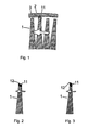
- Fig. 1 shows schematically a section through the axis of an exhaust gas turbine, wherein only a small section in the region of the rotor blades 1 and the rotor blades surrounding the housing wall 2 is shown. The direction of rotation of the turbine wheel is indicated by the arrow.
- the rotor blade according to the invention equipped with a cleaning element 11 is formed in the illustrated embodiment in the radial direction longer than the other blades. This ensures that impurities 3, which deposit on the inside of the housing wall 2 in the course of operation of the exhaust gas turbine, are only detected by the cleaning elements, and do not affect the tips of the other blades.
- the cleaning elements on the blade tips may comprise an abrasive coating.
- a layer of, for example, cubic boron nitrides (cBN), chromium carbide (CrC) or tungsten carbide-chromium carbide non-rods (WC-CrC-Ni) or similar, abrasion-resistant materials is applied to the blade tip of the relevant rotor blades.
- the coating may comprise the entire blade tip of the blade, or only on the pressure side, i. be mounted on the front side in the direction of the turbine wheel, and not on the suction side.
- the coated blade tip as a cleaning element has the advantage that even with prolonged operation and heavy contamination, the blade is not damaged at the radially outer tip.
- the tip is also not shortened in the radial direction, so that the air gap between the housing wall and the other, equipped without cleaning element blades can be kept constant. The maintenance of the cleaning element allows permanent cleaning of the area radially outside the blades.
- FIG. 2 shows a second embodiment of the cleaning element according to the invention.
- a cutting edge 12 is provided in the radially outermost region of the blade tip.
- This cutting edge which is advantageously also made of an abrasion-resistant material 11 or coated with such, ensures a clean cut through the deposits on the inside of the housing wall. If the cutting edge, as shown in Fig. 3, in the direction of the pressure side, ie in the running direction of the turbine wheel, inclined, the Cutting effect can be additionally improved.
- the uppermost layer of the deposit is continuously planed with the cutting edge guided almost parallel to the surface of the deposit. The resistance of the cleaning element when removing the deposit can be reduced thanks to the cutting edge.
- the removed pollution is detected by the flow and fed with the exhaust gas to the exhaust pipes. If necessary, these particles are filtered with suitable filters from the exhaust gases.
- the cleaning device according to the invention is advantageously combined with a wet cleaning device known from the prior art.
- the sudden injection of cold cleaning fluid the distance between the blade tips and the surrounding housing parts may be subject to short-term thermal changes.
- the longer cleaning elements on the blade tips ensure that the remaining blades are not impaired.
- the cleaning elements according to the invention can be used both in the case of axial-flow exhaust gas turbines, the so-called axial turbines, and also in the case of exhaust gas turbines flowed radially or mixed, the so-called radial or mixed flow turbines.
- Such exhaust gas turbines can be used in exhaust gas turbochargers for driving a compressor or in power turbines for driving an electric generator.
Landscapes
- Engineering & Computer Science (AREA)
- Mechanical Engineering (AREA)
- General Engineering & Computer Science (AREA)
- Supercharger (AREA)
Abstract
Description
Die Erfindung bezieht sich auf das Gebiet der mit Abgasen von Brennkraftmaschinen beaufschlagten Strömungsmaschinen.The invention relates to the field of turbomachines subjected to exhaust gases of internal combustion engines.
Sie betrifft eine Reinigungsvorrichtung einer Abgasturbine.It relates to a cleaning device of an exhaust gas turbine.
Abgasturbinen, insbesondere in Abgasturboladern, werden in Verbindung mit einem Verbrennungsmotor verwendet. Das Abgas aus dem Verbrennungsmotor wird als Antriebsmittel zum Antreiben des Turbinenrades benutzt. Das Turbinenrad ist durch eine Welle mit dem Verdichterrad verbunden mit welchem die Ansaugluft, die dem Verbrennungsmotor zugeführt wird, komprimiert wird. Das auf die Laufschaufeln der Abgasturbine geführte Abgas enthält Verunreinigungen, welche durch unvollständige Verbrennung und durch Kraftstoffverunreinigungen verursacht werden. Die Menge an Verunreinigungen, die der Verbrennungsmotor mit dem Abgas abgibt, ist stark vom verwendeten Kraftstoff abhängig. Wird ein schmutziger Kraftstoff verwendet, beispielsweise Schweröl (HFO), können beträchtliche Mengen an Verunreinigungen mit dem Abgas abgegeben werden.Exhaust gas turbines, in particular in exhaust gas turbochargers, are used in conjunction with an internal combustion engine. The exhaust gas from the internal combustion engine is used as a drive means for driving the turbine wheel. The turbine wheel is connected by a shaft to the compressor wheel with which the intake air, which is supplied to the internal combustion engine, is compressed. The exhaust gas carried on the blades of the exhaust gas turbine contains impurities caused by incomplete combustion and fuel contamination. The amount of impurities that the internal combustion engine emits with the exhaust gas is heavily dependent on the fuel used. If a dirty fuel is used, such as heavy fuel oil (HFO), significant amounts of pollutants can be released with the exhaust gas.
Die Verunreinigungen im Abgas führen unter anderem zu Ablagerungen auf den, den Strömungskanal bildenden Gehäuseteilen rund um das Turbinenrad. Insbesondere im Bereich radial ausserhalb der schnell rotierenden Laufschaufeln kommt es durch die radial nach aussen verdrängten Schmutzpartikel vermehrt zu Ablagerungen. Diese Ablagerungen führen dazu, dass sich der zwischen den Spitzen der Laufschaufeln und den gegenüberliegend angeordneten Gehäuseteilen ausgebildete Luftspalt (Clearance) verringert und es früher oder später zum Kontakt zwischen den Ablagerungen und den Laufschaufeln kommt. Dadurch wird einerseits das Turbinenrad abgebremst, andererseits können aber auch die Laufschaufeln Schaden nehmen, indem die Laufschaufelspitzen durch die stetige Reibung abgeschliffen werden.Among other things, the impurities in the exhaust gas lead to deposits on the housing parts forming the flow channel around the turbine wheel. Particularly in the area radially outside the rapidly rotating blades, deposits are increasingly generated by the dirt particles displaced radially outward. These deposits tend to reduce the air gap (clearance) formed between the tips of the blades and the opposing body portions, and sooner or later contact between the deposits and the blades occurs. As a result, on the one hand, the turbine wheel is braked, On the other hand, however, the blades can be damaged by the blade tips are abraded by the constant friction.
Um einen dauerhaft störungsfreien Betrieb bei voller Leistungsfähigkeit gewährleisten zu können, werden in der Regel die verunreinigten Teile in regelmässigen Abständen mittels einer in den Abgasstrom im Strömungskanal eingespritzten Reinigungsflüssigkeit von den Ablagerungen befreit.In order to ensure a permanently trouble-free operation at full capacity, the contaminated parts are usually freed from the deposits at regular intervals by means of a cleaning liquid injected into the exhaust gas flow in the flow channel.
Aus
Eine ähnliche Vorrichtung ist aus
Aus
Die Aufgabe der Erfindung besteht darin, eine Abgasturbine mit einer vereinfachten Reinigungsvorrichtung zu schaffen.The object of the invention is to provide an exhaust gas turbine with a simplified cleaning device.
Erfindungsgernäss umfasst die Reinigungsvorrichtung an den Laufschaufeln der Abgasturbine angeordnete Reinigungselemente, weiche den Bereich radial ausserhalb der Laufschaufeln im Betrieb laufend von allzu starker Verunreinigung befreien.According to the invention, the cleaning device comprises cleaning elements arranged on the rotor blades of the exhaust-gas turbine, which continually clear the region radially outside the rotor blades of excessive contamination during operation.
Die erfindungsgemässen Reinigungselemente sind in einer ersten Ausführungsform als beschichtete Laufschaufelspitzen ausgebildet. Diese beschichteten Laufschaufelspitzen reiben die an der radialen Innenseite des Gehäuses der Abgasturbine angelagerte Verschmutzung ab.The inventive cleaning elements are formed in a first embodiment as coated blade tips. These coated blade tips rub off the deposited on the radial inside of the housing of the exhaust turbine pollution.
Sind erfindungsgemäss nur ein Teil der Laufschaufeln mit Reinigungselementen versehen, sind diese Laufschaufeln vorteilhafterweise in radialer Richtung länger ausgebildet als die übrigen Laufschaufeln.If, according to the invention, only a part of the moving blades is provided with cleaning elements, these moving blades are advantageously designed to be longer in the radial direction than the remaining moving blades.
Vorteilhafterweise sind von der Vielzahl von Laufschaufeln nur einige wenige mit Reinigungselementen ausgestattet. Dadurch wird der Reinigungseffekt nicht beeinträchtigt, aber die Herstellungskosten für das Turbinenrad können tief gehalten werden.Advantageously, of the plurality of blades only a few are equipped with cleaning elements. As a result, the cleaning effect is not impaired, but the manufacturing cost of the turbine wheel can be kept low.
Um die Abtragung der Verunreinigungen effizienter zu gestalten, können die Reinigungselemente mit Schneidekanten versehen werden, welche radial nach aussen oder aber zur Druckseite hin geneigt ausgerichtet sein können. Die Verunreinigungen werden mit der nahezu parallel zur Oberfläche der Gehäusewand geführten Schneidekante kontinuierlich abgehobelt.In order to make the removal of the contaminants more efficient, the cleaning elements can be provided with cutting edges, which can be oriented radially outwards or inclined towards the pressure side. The impurities are continuously planed down with the cutting edge guided almost parallel to the surface of the housing wall.
Nachfolgend werden verschiedene Ausführungsformen der Erfindung anhand von Zeichnungen detailliert erläutert. Hierbei zeigt
- Fig. 1
- schematisch einen Schnitt durch ein Abgasturbinenrad mit einem erfndungsgemässen Reinigungselement im Bereich der Spitzen der Turbinenlaufschaufeln,
- Fig. 2
- die Laufschaufel mit dem Reinigungselement nach Fig. 1, mit einer zusätzlichen Schneidekante, und
- Fig.3
- die Laufschaufel mit dem Reinigungselement nach Fig. 1, mit einer zusätzlichen in Druckrichtung geneigten Schneidekante.
- Fig. 1
- 1 schematically shows a section through an exhaust-gas turbine wheel with a cleaning element according to the invention in the region of the tips of the turbine blades,
- Fig. 2
- the blade with the cleaning element of FIG. 1, with an additional cutting edge, and
- Figure 3
- the blade with the cleaning element of FIG. 1, with an additional inclined in the printing direction cutting edge.
Das Laufrad einer Abgasturbine umfasst eine Nabe mit darauf befestigten Laufschaufeln. Je nach Grösse und Anwendungsbereich der Abgasturbine umfasst ein Laufrad zwischen einigen wenigen und mehreren Dutzend Laufschaufeln.The impeller of an exhaust gas turbine includes a hub with blades mounted thereon. Depending on the size and scope of the exhaust gas turbine, an impeller includes between a few and several dozen blades.
Sowohl bei axial angeströmten Abgasturbinen, als auch bei radial oder gemischt angeströmten Abgasturbinen wird im Bereich der Laufschaufeln der die Abgase über das Turbinenrad führende Strömungskanal durch die radial innenliegende Nabe des Turbinenrades und einer radial ausserhalb des Turbinenrades angeordneten Gehäusewand gebildet.In the case of axial flowed exhaust gas turbines, as well as in the case of exhaust gas turbines flowed in radially or mixed, the flow channel passing through the turbine wheel through the radially inner hub of the exhaust gas in the region of the rotor blades Turbine wheel and a radially outside the turbine wheel arranged housing wall formed.
Fig. 1 zeigt schematisch einen Schnitt durch die Achse einer Abgasturbine, wobei nur ein kleiner Ausschnitt im Bereich der Laufschaufeln 1 und der die Laufschaufeln radial umgebenden Gehäusewand 2 dargestellt ist. Die Drehrichtung des Turbinenrades ist mit dem Pfeil angedeutet.Fig. 1 shows schematically a section through the axis of an exhaust gas turbine, wherein only a small section in the region of the
Die erfindungsgemäss mit einem Reinigungselement 11 ausgestattete Laufschaufel ist in der dargestellten Ausführungsform in radialer Richtung länger ausgebildet als die übrigen Laufschaufeln. Dadurch ist sichergestellt, dass Verunreinigungen 3, welche sich auf der Innenseite der Gehäusewand 2 im Laufe des Betriebes der Abgasturbine ablagern, nur von den Reinigungselementen erfasst werden, und nicht die Spitzen der übrigen Laufschaufeln beeinträchtigen.The rotor blade according to the invention equipped with a
Die Reinigungselemente auf den Schaufelspitzen können eine abrasive Beschichtung umfassen. Dabei ist auf der Schaufelspitze der betreffenden Laufschaufeln eine Schicht aus beispielsweise kubischen Bor-Nitriden (cBN), Chrom-Karbid (CrC) oder Wolframcarbid-Chromkarbid-Niekel (WC-CrC-Ni) oder ähnlichen, abriebfesten Materialien aufgetragen. Die Beschichtung kann die gesamte Schaufelspitze der Laufschaufel umfassen, oder aber nur auf der Druckseite, d.h. auf der in Laufrichtung des Turbinenrades vorderen Seite, und nicht auf der Saugseite, angebracht sein. Die beschichtete Schaufelspitze als Reinigungselement hat den Vorteil, dass auch bei längerem Betrieb und starker Verschmutzung die Laufschaufel an der radial äusseren Spitze nicht beschädigt wird. Die Spitze wird auch nicht in radialer Richtung gekürzt, so dass der Luftspalt zwischen der Gehäusewand und den übrigen, ohne Reinigungselement ausgestattete Laufschaufeln konstant gehalten werden kann. Die Erhaltung des Reinigungselements ermöglicht eine dauerhafte Reinigung des Bereiches radial ausserhalb der Laufschaufeln.The cleaning elements on the blade tips may comprise an abrasive coating. In this case, a layer of, for example, cubic boron nitrides (cBN), chromium carbide (CrC) or tungsten carbide-chromium carbide non-rods (WC-CrC-Ni) or similar, abrasion-resistant materials is applied to the blade tip of the relevant rotor blades. The coating may comprise the entire blade tip of the blade, or only on the pressure side, i. be mounted on the front side in the direction of the turbine wheel, and not on the suction side. The coated blade tip as a cleaning element has the advantage that even with prolonged operation and heavy contamination, the blade is not damaged at the radially outer tip. The tip is also not shortened in the radial direction, so that the air gap between the housing wall and the other, equipped without cleaning element blades can be kept constant. The maintenance of the cleaning element allows permanent cleaning of the area radially outside the blades.
Fig. 2 zeigt eine zweite Ausführungsform des erfindungsgemässen Reinigungselementes, Im radial äussersten Bereich der Schaufelspitze ist eine Schneidekante 12 vorgesehen. Diese Schneidekante, welche vorteilhafterweise ebenfalls aus einem abriebfesten Material 11 gefertigt oder mit einem solchen beschichtet ist, sorgt für einen sauberen Schnitt durch die Ablagerungen an der Innenseite der Gehäusewand. Wird die Schneidekante, wie in Fig. 3 dargestellt, in Richtung der Druckseite, also in Laufrichtung des Turbinenrades, geneigt, kann der Schneideffekt zusätzlich verbessert werden. Die oberste Schicht der Ablagerung wird mit der nahezu parallel zur Oberfläche der Ablagerung geführten Schneidekante kontinuierlich abgehobelt. Der Widerstand des Reinigungselements beim Abtragen der Ablagerung kann dank der Schneidekante reduziert werden.FIG. 2 shows a second embodiment of the cleaning element according to the invention. In the radially outermost region of the blade tip, a
Die abgetragene Verschmutzung wird von der Strömung erfasst und mit dem Abgas den Auspuffrohren zugeführt. Gegebenenfalls werden diese Verschmutzungspartikel mit geeigneten Filtern aus den Abgasen gefiltert.The removed pollution is detected by the flow and fed with the exhaust gas to the exhaust pipes. If necessary, these particles are filtered with suitable filters from the exhaust gases.
Um eine optimale Reinigung zu erzielen, wird die erfindungsgernässe Reinigungsvorrichtung vorteilhafterweise mit einer aus dem Stand der Technik bekannten Feuchtreinigungsvorrichtung kombiniert. In diesem Fall kann beim plötzlichen Einspritzen von kalter Reinigungsflüssigkeit der Abstand zwischen Laufschaufelspitzen und den umliegenden Gehäuseteilen kurzzeitig thermisch bedingten Änderungen unterliegen. Sollte es im Extremfall gar zu einem kurzzeitigen Kontakt zwischen Laufschaufelspitze und Gehäusewand kommen, sorgen die länger Reinigungselemente an den Laufschaufelspitzen dafür, dass die übrigen Laufschaufeln nicht beeinträchtig werden.In order to achieve optimum cleaning, the cleaning device according to the invention is advantageously combined with a wet cleaning device known from the prior art. In this case, the sudden injection of cold cleaning fluid, the distance between the blade tips and the surrounding housing parts may be subject to short-term thermal changes. In extreme cases, if there is even a short-term contact between the blade tip and the housing wall, the longer cleaning elements on the blade tips ensure that the remaining blades are not impaired.
Die erfindungsgemässen Reinigungselemente lassen sich sowohl bei axial angeströmten Abgasturbinen, den sogenannten Axialturbinen, als auch bei radial oder gemischt angeströmten Abgasturbinen, den sogenannten Radial- oder MixedFlow-Turbinen eingesetzt werden. Solche Abgasturbinen können bei Abgasturboladern zum Antrieb eines Verdichters oder bei Nutzturbinen zum Antrieb eines elektrischen Generators eingesetzt werden.The cleaning elements according to the invention can be used both in the case of axial-flow exhaust gas turbines, the so-called axial turbines, and also in the case of exhaust gas turbines flowed radially or mixed, the so-called radial or mixed flow turbines. Such exhaust gas turbines can be used in exhaust gas turbochargers for driving a compressor or in power turbines for driving an electric generator.
- 11
- Laufschaufelblade
- 22
- Gehäusewandhousing wall
- 1111
- Reinigungselement, BeschichtungCleaning element, coating
- 1212
- Schneidekantecutting edge
- 33
- Ablagerungendeposits
Claims (8)
dadurch gekennzeichnet, dass die Reinigungsvorrichtung auf den Spitzen der Laufschaufeln (1) des Turbinenrades angeordnete Reinigungselemente (11) umfasst.Exhaust gas turbine, comprising a turbine wheel with a plurality of blades (1), a turbine housing and a cleaning device for removing dirt (3), which deposits on the inside of a radially outside the blades of the exhaust turbine housing wall (2),
characterized in that the cleaning device on the tips of the blades (1) of the turbine wheel arranged cleaning elements (11).
Priority Applications (1)
| Application Number | Priority Date | Filing Date | Title |
|---|---|---|---|
| EP06405074A EP1820938A1 (en) | 2006-02-20 | 2006-02-20 | Cleaning elements on blade tips of an exhaust turbine |
Applications Claiming Priority (1)
| Application Number | Priority Date | Filing Date | Title |
|---|---|---|---|
| EP06405074A EP1820938A1 (en) | 2006-02-20 | 2006-02-20 | Cleaning elements on blade tips of an exhaust turbine |
Publications (1)
| Publication Number | Publication Date |
|---|---|
| EP1820938A1 true EP1820938A1 (en) | 2007-08-22 |
Family
ID=36685747
Family Applications (1)
| Application Number | Title | Priority Date | Filing Date |
|---|---|---|---|
| EP06405074A Withdrawn EP1820938A1 (en) | 2006-02-20 | 2006-02-20 | Cleaning elements on blade tips of an exhaust turbine |
Country Status (1)
| Country | Link |
|---|---|
| EP (1) | EP1820938A1 (en) |
Cited By (7)
| Publication number | Priority date | Publication date | Assignee | Title |
|---|---|---|---|---|
| EP2204548A1 (en) | 2009-01-06 | 2010-07-07 | ABB Turbo Systems AG | Exhaust gas turbine with shroud and corresponding exhaust turbocharger |
| WO2011002570A1 (en) * | 2009-06-30 | 2011-01-06 | General Electric Company | Rotor blade and method for reducing tip rub loading |
| FR2962762A1 (en) * | 2010-07-19 | 2012-01-20 | Snecma | Movable blade for use in rotor disk of high pressure compressor of e.g. turbojet engine of aircraft, has front side surface provided with cutting face at its radially outer end, where cutting face forms non-zero cutting angle with surface |
| US8657570B2 (en) | 2009-06-30 | 2014-02-25 | General Electric Company | Rotor blade with reduced rub loading |
| US8662834B2 (en) | 2009-06-30 | 2014-03-04 | General Electric Company | Method for reducing tip rub loading |
| CN108869032A (en) * | 2018-02-23 | 2018-11-23 | 孙远 | A kind of cleaning method of vehicle turbine pressure charging system |
| EP3546703A1 (en) * | 2018-03-29 | 2019-10-02 | Siemens Aktiengesellschaft | Turbine blade for a gas turbine |
Citations (7)
| Publication number | Priority date | Publication date | Assignee | Title |
|---|---|---|---|---|
| CH335901A (en) | 1955-11-10 | 1959-01-31 | Sulzer Ag | Turbine with a device for introducing a cleaning medium into the blade channel |
| DE2008503A1 (en) | 1969-07-28 | 1971-02-11 | VEB Bergmann Borsig/Gorlitzer Ma schinenbau, Werk Berlin, Berlin | Device for washing the blades of gas turbines |
| DE3102575A1 (en) * | 1980-05-01 | 1982-01-28 | General Electric Co., Schenectady, N.Y. | "TIP CAP FOR A ROTOR BLADE AND METHOD FOR REPLACING THE SAME" |
| DE3515825A1 (en) | 1984-05-11 | 1985-11-14 | Elliott Turbomachinery Co., Inc., Jeannette, Pa. | METHOD AND DEVICE FOR CONTROLLING THE CLEANING OF THE TURBINE BLADES OF AN EXHAUST TURBOCHARGER |
| GB2225388A (en) * | 1988-10-01 | 1990-05-30 | Rolls Royce Plc | Rotor blade tip clearance setting in gas turbine engines |
| EP0702130A2 (en) * | 1994-09-16 | 1996-03-20 | Mtu Motoren- Und Turbinen-Union MàNchen Gmbh | Blade tip with cutting surface layer |
| WO2002025065A1 (en) * | 2000-09-25 | 2002-03-28 | Alstom (Switzerland) Ltd | Seal system |
-
2006
- 2006-02-20 EP EP06405074A patent/EP1820938A1/en not_active Withdrawn
Patent Citations (7)
| Publication number | Priority date | Publication date | Assignee | Title |
|---|---|---|---|---|
| CH335901A (en) | 1955-11-10 | 1959-01-31 | Sulzer Ag | Turbine with a device for introducing a cleaning medium into the blade channel |
| DE2008503A1 (en) | 1969-07-28 | 1971-02-11 | VEB Bergmann Borsig/Gorlitzer Ma schinenbau, Werk Berlin, Berlin | Device for washing the blades of gas turbines |
| DE3102575A1 (en) * | 1980-05-01 | 1982-01-28 | General Electric Co., Schenectady, N.Y. | "TIP CAP FOR A ROTOR BLADE AND METHOD FOR REPLACING THE SAME" |
| DE3515825A1 (en) | 1984-05-11 | 1985-11-14 | Elliott Turbomachinery Co., Inc., Jeannette, Pa. | METHOD AND DEVICE FOR CONTROLLING THE CLEANING OF THE TURBINE BLADES OF AN EXHAUST TURBOCHARGER |
| GB2225388A (en) * | 1988-10-01 | 1990-05-30 | Rolls Royce Plc | Rotor blade tip clearance setting in gas turbine engines |
| EP0702130A2 (en) * | 1994-09-16 | 1996-03-20 | Mtu Motoren- Und Turbinen-Union MàNchen Gmbh | Blade tip with cutting surface layer |
| WO2002025065A1 (en) * | 2000-09-25 | 2002-03-28 | Alstom (Switzerland) Ltd | Seal system |
Cited By (8)
| Publication number | Priority date | Publication date | Assignee | Title |
|---|---|---|---|---|
| EP2204548A1 (en) | 2009-01-06 | 2010-07-07 | ABB Turbo Systems AG | Exhaust gas turbine with shroud and corresponding exhaust turbocharger |
| WO2011002570A1 (en) * | 2009-06-30 | 2011-01-06 | General Electric Company | Rotor blade and method for reducing tip rub loading |
| US8657570B2 (en) | 2009-06-30 | 2014-02-25 | General Electric Company | Rotor blade with reduced rub loading |
| US8662834B2 (en) | 2009-06-30 | 2014-03-04 | General Electric Company | Method for reducing tip rub loading |
| FR2962762A1 (en) * | 2010-07-19 | 2012-01-20 | Snecma | Movable blade for use in rotor disk of high pressure compressor of e.g. turbojet engine of aircraft, has front side surface provided with cutting face at its radially outer end, where cutting face forms non-zero cutting angle with surface |
| CN108869032A (en) * | 2018-02-23 | 2018-11-23 | 孙远 | A kind of cleaning method of vehicle turbine pressure charging system |
| EP3546703A1 (en) * | 2018-03-29 | 2019-10-02 | Siemens Aktiengesellschaft | Turbine blade for a gas turbine |
| WO2019185713A1 (en) | 2018-03-29 | 2019-10-03 | Siemens Aktiengesellschaft | Turbine rotor blade for a gas turbine |
Similar Documents
| Publication | Publication Date | Title |
|---|---|---|
| EP1820938A1 (en) | Cleaning elements on blade tips of an exhaust turbine | |
| EP1778953B1 (en) | Exhaust turbine cleaning device | |
| EP2054586B1 (en) | Gas turbine | |
| EP1917421B1 (en) | Compressor, compressor wheel, cleaning attachment and exhaust turbocharger | |
| EP1706597B1 (en) | Gas turbine with axially displaceable rotor | |
| DE19536017B4 (en) | Turbocharger drive and planetary bearing for it | |
| DE102011108195B4 (en) | Turbine for an exhaust gas turbocharger | |
| DE102013222067B4 (en) | Oil deflector and oil seal system | |
| EP2009288A2 (en) | Turbocharger with integrated separator | |
| EP1862641A1 (en) | Annular flow channel for axial flow turbomachine | |
| EP3080399B1 (en) | Turbocharger | |
| EP3567227B1 (en) | Centrifugal debris pre-separator for turbine engine oil filter | |
| DE102013112771A1 (en) | Jet engine with a device for spraying oil | |
| DE102011082089A1 (en) | Cleaning device of an exhaust gas turbine | |
| DE102007019884A1 (en) | Compressor for an exhaust gas turbocharger | |
| EP2313615B2 (en) | Blade arrangement of a gas turbine | |
| EP2562430A1 (en) | Method for washing an axial compressor | |
| DE3724385C2 (en) | ||
| EP2963243A1 (en) | Flow engine with blades having blade tips lowering towards the trailing edge | |
| EP1687512B1 (en) | Turbocharger with a cleaning device | |
| DE102016122696A1 (en) | Entry guide wheel for a turbomachine | |
| EP1549838B1 (en) | Centrifuge, in particular for separating the soot from an exhaust gas flow of an internal combustion engine | |
| DE102011009564A1 (en) | Bearing unit for shaft of turbo charger, has outer ring, inner ring and two bearing series guided between outer ring and inner ring | |
| EP1707742A1 (en) | Turbine blade with dirt collector | |
| DE202009016174U1 (en) | Exhaust gas turbine with a self-cleaning coating |
Legal Events
| Date | Code | Title | Description |
|---|---|---|---|
| PUAI | Public reference made under article 153(3) epc to a published international application that has entered the european phase |
Free format text: ORIGINAL CODE: 0009012 |
|
| AK | Designated contracting states |
Kind code of ref document: A1 Designated state(s): AT BE BG CH CY CZ DE DK EE ES FI FR GB GR HU IE IS IT LI LT LU LV MC NL PL PT RO SE SI SK TR |
|
| AX | Request for extension of the european patent |
Extension state: AL BA HR MK YU |
|
| AKX | Designation fees paid | ||
| REG | Reference to a national code |
Ref country code: DE Ref legal event code: 8566 |
|
| STAA | Information on the status of an ep patent application or granted ep patent |
Free format text: STATUS: THE APPLICATION IS DEEMED TO BE WITHDRAWN |
|
| 18D | Application deemed to be withdrawn |
Effective date: 20080223 |