EP2204344A1 - Nip device and nip method - Google Patents
Nip device and nip method Download PDFInfo
- Publication number
- EP2204344A1 EP2204344A1 EP08846122A EP08846122A EP2204344A1 EP 2204344 A1 EP2204344 A1 EP 2204344A1 EP 08846122 A EP08846122 A EP 08846122A EP 08846122 A EP08846122 A EP 08846122A EP 2204344 A1 EP2204344 A1 EP 2204344A1
- Authority
- EP
- European Patent Office
- Prior art keywords
- gas
- jetting
- film
- nip
- storage chamber
- Prior art date
- Legal status (The legal status is an assumption and is not a legal conclusion. Google has not performed a legal analysis and makes no representation as to the accuracy of the status listed.)
- Granted
Links
Images
Classifications
-
- B—PERFORMING OPERATIONS; TRANSPORTING
- B65—CONVEYING; PACKING; STORING; HANDLING THIN OR FILAMENTARY MATERIAL
- B65H—HANDLING THIN OR FILAMENTARY MATERIAL, e.g. SHEETS, WEBS, CABLES
- B65H20/00—Advancing webs
- B65H20/02—Advancing webs by friction roller
-
- B—PERFORMING OPERATIONS; TRANSPORTING
- B65—CONVEYING; PACKING; STORING; HANDLING THIN OR FILAMENTARY MATERIAL
- B65H—HANDLING THIN OR FILAMENTARY MATERIAL, e.g. SHEETS, WEBS, CABLES
- B65H18/00—Winding webs
- B65H18/08—Web-winding mechanisms
- B65H18/10—Mechanisms in which power is applied to web-roll spindle
- B65H18/103—Reel-to-reel type web winding and unwinding mechanisms
-
- B—PERFORMING OPERATIONS; TRANSPORTING
- B65—CONVEYING; PACKING; STORING; HANDLING THIN OR FILAMENTARY MATERIAL
- B65H—HANDLING THIN OR FILAMENTARY MATERIAL, e.g. SHEETS, WEBS, CABLES
- B65H23/00—Registering, tensioning, smoothing or guiding webs
- B65H23/04—Registering, tensioning, smoothing or guiding webs longitudinally
- B65H23/18—Registering, tensioning, smoothing or guiding webs longitudinally by controlling or regulating the web-advancing mechanism, e.g. mechanism acting on the running web
- B65H23/188—Registering, tensioning, smoothing or guiding webs longitudinally by controlling or regulating the web-advancing mechanism, e.g. mechanism acting on the running web in connection with running-web
-
- B—PERFORMING OPERATIONS; TRANSPORTING
- B65—CONVEYING; PACKING; STORING; HANDLING THIN OR FILAMENTARY MATERIAL
- B65H—HANDLING THIN OR FILAMENTARY MATERIAL, e.g. SHEETS, WEBS, CABLES
- B65H2406/00—Means using fluid
- B65H2406/10—Means using fluid made only for exhausting gaseous medium
- B65H2406/11—Means using fluid made only for exhausting gaseous medium producing fluidised bed
-
- B—PERFORMING OPERATIONS; TRANSPORTING
- B65—CONVEYING; PACKING; STORING; HANDLING THIN OR FILAMENTARY MATERIAL
- B65H—HANDLING THIN OR FILAMENTARY MATERIAL, e.g. SHEETS, WEBS, CABLES
- B65H2701/00—Handled material; Storage means
- B65H2701/10—Handled articles or webs
- B65H2701/17—Nature of material
- B65H2701/171—Physical features of handled article or web
- B65H2701/1719—Photosensitive, e.g. exposure, photographic or phosphor
Definitions
- the present invention relates to a nip apparatus and a nip method which press a material such as a band-shaped film to be treated on a supporting member such as a roll.
- a nip apparatus which a band-shaped film is conveyed while being supported on a rotating roll
- a part of air is enclosed in a film
- the enclosed air forms air bubbles causes a partial elevation of film.
- the partial elevation of the film changes a gap between the film surface and a post-processing device through which the film is subjected to post-processing such as coating or plasma processing, causing problem of resulting in incapability of uniform post-processing.
- a film supported on a roll (referred to as a supporting roll) is pressed against the roll at an appropriate pressure employing a roll with elasticity (referred to as an elastic roll), thereby bringing the film into close contact with the supporting roll.
- the technique employing the elastic roll dirt on the elastic roll surface is transferred to the film, since the elastic roll is in contact with the film. Further, the technique employing the elastic roll has problem in that since the elastic roll rotates while deforming along the outer circumference of the supporting roll, microscopic slippage takes place at the interface between the film and the elastic roll, producing scratches due to slippage on the film surface.
- Patent Document 1 In order to prevent the dirt transfer or scratches due to slippage as described above, a technique is disclosed in, for example, Patent Document 1, in which compressed air is jetted onto a band-shaped film supported on a supporting roll, thereby improving contact between the film and the roll without employing an elastic roll.
- Patent Document 2 A technique is disclosed in Patent Document 2 in which air present between a film and a supporting roll having numerous minute holes in the surface is sucked through the minute holes, thereby improving contact between the film and the roll.
- Patent Document 1 Japanese Patent O.P I. Publication No. 59-92856
- Patent Document 2 Japanese Patent O.P I. Publication No. 2003-171044
- Patent Document 2 has problem in that scratches due to edges of the numerous minute holes are produced on the surface on the side facing the roll of the film.
- An object of the invention is to provide a nip apparatus and a nip method which reduce consumption of gas used without scratches which are produced when a material to be treated (such as a band-shaped film and the like) is pressed against a support (such as a roll and the like).
- a material to be treated such as a band-shaped film and the like
- a support such as a roll and the like
- a gas storage chamber which stores gas with a pressure higher than outside atmospheric pressure, is disposed at a position facing a film, and a band-shaped film can be conveyed while being pressed against a roll with a reduced consumption of gas.
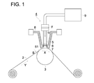
- Fig. 1 is a schematic drawing showing the structure of the nip apparatus 1 in the invention.
- the dip device 1 comprises a roll 3 and a gas jetting device 4, a band-shaped film 2 being supported on the roll 3 and the gas jetting device jetting gas onto the band-shaped film 2 supported on the roll 3.
- a jetting nozzle 5 as a gas introduction pipe is disposed at a position facing the film 2.
- a surrounding wall 6 is disposed at the tip end of the jetting nozzle 5, the surrounding wall connecting the jetting nozzle 5 and extending to the vicinity of the surface of the film 2.
- the surrounding wall 6 has a port diameter greater than the pipe diameter of the jetting nozzle 5, constituting a gas storage chamber 7.
- the gas storage chamber which has a diameter (or a sectional area) greater than a pipe diameter (or a sectional area) of the gas introduction pipe, and is not completely opened, makes it possible to jet a high pressure gas onto an area broader than an area onto which a nozzle jets the gas, providing an excellent nip effect and reducing gas consumption amount.
- the nip apparatus has a structure that the stream diameter (or sectional area) of the gas stream increases in the gas storage chamber but a relatively high pressure of the gas is maintained.
- the gas storage chamber comprises a gas jetting port and jets gas onto the film 2, whereby the film 2 can be pressed against the roll 3.
- the jetting nozzle 5 and the surrounding wall 6 are explained as being different members but they may be integrated into one body.
- the roll 3 rotates in the direction as shown by an arrow Y, and the band-shaped film moves in the direction as shown by an arrow X.
- Gas jetted by the gas jetting device is temporarily stored in a space formed from the surrounding wall, the end surface of the jetting nozzle and the surface of the film 2. This space forms a gas storage chamber 7.
- Gas G which is ejected from the gas jetting device 4 and has a pressure higher than outside atmospheric pressure, is stored in the gas storage chamber 7.
- the gas G with higher pressure is discharged from the gas storage chamber 7 through a gap S between the surrounding wall 6 and the film 2.
- a filter F for removing impurities in the gas G is provided in a path through which the gas G passes.
- the filter is provided between the gas jetting device 4 and a compressor 9 which compresses the gas G
- the gas jetting device 4 is explained as pressing gas against one portion of the band-shaped film surface.
- Plural gas jetting device may be provided in the width direction (from the front of the page to the back of the page) of the band-shaped film 4, thereby linearly applying uniform pressure to the surface in the width direction af the film.
- the gas jetting device can be a gas jetting device in the form of a slit capable of linearly jetting gas onto the entire surface in the width direction of the film.
- the jetting port of the gas storage chamber the sectional area of the gas storage chamber is larger than the tip port of the slit (the sectional area of the gas introduction pipe).
- a step may be carried out in which the pressed film is subjected to post-treatment such as coating, UV irradiation or plasma on that roll.
- the gas pressure GF was 1200 hPa in the device of the invention with the gas storage chamber 7, while the gas pressure GF was 2000 hPa in the conventional device without the gas storage chamber 7.
- the nip apparatus of the invention with the gas storage chamber 7 enabled to convey the film 2 while pressing the film against the roll 3 without causing scratches due to film slippage at a gas pressure GF of about 1.1 times the atmospheric pressure 1013 (hPa). This shows that the gas in the gas storage chamber 7 uniformly presses the film surface.
- the conventional nip apparatus required a gas pressure GF of about 2 times the atmospheric pressure, in order to obtain the same performance as described above.
- the nip apparatus of the invention comprising a gas storage chamber 7, which stores gas with a pressure higher than outside atmospheric pressure, enables to convey while pressing a band-shaped film against a roll in a reduced amount of gas.
Landscapes
- Treatments Of Macromolecular Shaped Articles (AREA)
- Advancing Webs (AREA)
- Registering, Tensioning, Guiding Webs, And Rollers Therefor (AREA)
- Processing And Handling Of Plastics And Other Materials For Molding In General (AREA)
Abstract
Description
- The present invention relates to a nip apparatus and a nip method which press a material such as a band-shaped film to be treated on a supporting member such as a roll.
- In a nip apparatus which a band-shaped film is conveyed while being supported on a rotating roll, when the film is provided on the roll, a part of air is enclosed in a film, the enclosed air forms air bubbles causes a partial elevation of film. The partial elevation of the film changes a gap between the film surface and a post-processing device through which the film is subjected to post-processing such as coating or plasma processing, causing problem of resulting in incapability of uniform post-processing.
- In order to solve such a problem, there is proposed a method in which a film supported on a roll (referred to as a supporting roll) is pressed against the roll at an appropriate pressure employing a roll with elasticity (referred to as an elastic roll), thereby bringing the film into close contact with the supporting roll.
- However, in the technique employing the elastic roll, dirt on the elastic roll surface is transferred to the film, since the elastic roll is in contact with the film. Further, the technique employing the elastic roll has problem in that since the elastic roll rotates while deforming along the outer circumference of the supporting roll, microscopic slippage takes place at the interface between the film and the elastic roll, producing scratches due to slippage on the film surface.
- In order to prevent the dirt transfer or scratches due to slippage as described above, a technique is disclosed in, for example, Patent Document 1, in which compressed air is jetted onto a band-shaped film supported on a supporting roll, thereby improving contact between the film and the roll without employing an elastic roll.
- A technique is disclosed in
Patent Document 2 in which air present between a film and a supporting roll having numerous minute holes in the surface is sucked through the minute holes, thereby improving contact between the film and the roll.
Patent Document 1: Japanese Patent O.P I. Publication No.59-92856
Patent Document 2: Japanese Patent O.P I. Publication No.2003-171044 - However, in the technique disclosed in Patent Document 1, it is necessary that the compressed air is continuously jetted on the film surface while maintaining a pressure higher than outside atmospheric pressure and consumption of the air is too large. The technique, when expensive gas such as a nitrogen gas needs to be employed as air to be compressed, increases the gas cost, and therefore, is not considered to be useful.
- The technique disclosed in
Patent Document 2 has problem in that scratches due to edges of the numerous minute holes are produced on the surface on the side facing the roll of the film. - An object of the invention is to provide a nip apparatus and a nip method which reduce consumption of gas used without scratches which are produced when a material to be treated (such as a band-shaped film and the like) is pressed against a support (such as a roll and the like).
- The above object of the invention can be attained by any one of the following constitutions.
- 1. A nip apparatus which presses a material to be treated provided on a supporting member against the supporting member by jetting gas onto the surface of the material, the nip apparatus comprising:
- a gas jetting device with a jetting opening disposed in a position facing the supporting member, the material being provided between the jetting opening and the supporting member,
- 2. The nip apparatus of item 1, wherein the gas storage chamber stores gas with a pressure higher than outside atmospheric pressure.
- 3. The nip apparatus of
item 1 or 2, further comprising a gas discharge device which sucks gas and discharges the sucked gas in the vicinity of a gap between the supporting member and the jetting opening. - 4. The nip apparatus of any one of items 1 through 3, wherein the supporting member is a rotatory roll and the material to be treated is a band-shaped film, the film being supported on the rotatory roll.
- 5. A nip method which presses a material to be treated provided on a supporting member against the support member by jetting gas onto the surface of the material, the nip method comprising the steps of:
- introducing gas into a gas introduction pipe with a specific diameter; and
- discharging gas from a gas storage chamber with a jetting opening, wherein the gas storage chamber connects the gas introduction pipe and has a sectional area greater than that of the gas introduction pipe.
- In the invention, a gas storage chamber, which stores gas with a pressure higher than outside atmospheric pressure, is disposed at a position facing a film, and a band-shaped film can be conveyed while being pressed against a roll with a reduced consumption of gas.
-
-
Fig. 1 is a schematic drawing showing the structure of the nip apparatus 1 in the invention. -
- 1. Nip apparatus
- 2. Film
- 3. Roll
- 4. Gas jetting device
- 5. Jetting nozzle
- 6. Surrounding wall
- 7. Gas storage chamber
- 8. Gas discharge device
- The preferred embodiment of the invention will be explained below. The present invention will be explained employing the embodiment illustrated but the present invention is not limited thereto. A definite explanation of the preferred embodiment of the invention made below shows the best mode of the invention but does not limit the terms or technical scope described.
- Next, the present invention will be explained, referring to the drawing.
-
Fig. 1 is a schematic drawing showing the structure of the nip apparatus 1 in the invention. In the drawing, the dip device 1 comprises a roll 3 and a gas jetting device 4, a band-shaped film 2 being supported on the roll 3 and the gas jetting device jetting gas onto the band-shaped film 2 supported on the roll 3. - In the gas jetting device 4, a jetting nozzle 5 as a gas introduction pipe is disposed at a position facing the
film 2. A surrounding wall 6 is disposed at the tip end of the jetting nozzle 5, the surrounding wall connecting the jetting nozzle 5 and extending to the vicinity of the surface of thefilm 2. The surrounding wall 6 has a port diameter greater than the pipe diameter of the jetting nozzle 5, constituting a gas storage chamber 7. The gas storage chamber, which has a diameter (or a sectional area) greater than a pipe diameter (or a sectional area) of the gas introduction pipe, and is not completely opened, makes it possible to jet a high pressure gas onto an area broader than an area onto which a nozzle jets the gas, providing an excellent nip effect and reducing gas consumption amount. Namely, the nip apparatus has a structure that the stream diameter (or sectional area) of the gas stream increases in the gas storage chamber but a relatively high pressure of the gas is maintained. - The gas storage chamber comprises a gas jetting port and jets gas onto the
film 2, whereby thefilm 2 can be pressed against the roll 3. Herein, the jetting nozzle 5 and the surrounding wall 6 are explained as being different members but they may be integrated into one body. - The roll 3 rotates in the direction as shown by an arrow Y, and the band-shaped film moves in the direction as shown by an arrow X. Gas jetted by the gas jetting device is temporarily stored in a space formed from the surrounding wall, the end surface of the jetting nozzle and the surface of the
film 2. This space forms a gas storage chamber 7. Gas G , which is ejected from the gas jetting device 4 and has a pressure higher than outside atmospheric pressure, is stored in the gas storage chamber 7. The gas G with higher pressure is discharged from the gas storage chamber 7 through a gap S between the surrounding wall 6 and thefilm 2. The gas, G discharged from the gas storage chamber 7, accumulates in the nip apparatus 1 unless any processing is carried out, and when the accumulated gas leaks from the device, the leaked gas has problem in that it may be harmful to human body due to kinds of gas used. Accordingly, a gas discharge device 8, which sucks the gas G and discharges the gas toward a predetermined section, is provided in the vicinity of the gap S so as not to allow extra gas to accumulate in the nip apparatus 1. In this case, it is preferred that the amount of the sucked gas is larger than the jetting amount of gas jetted by the gas jetting device. - In the gas jetting device 4, a filter F for removing impurities in the gas G is provided in a path through which the gas G passes. In the embodiment of the invention, the filter is provided between the gas jetting device 4 and a compressor 9 which compresses the gas G In this drawing, the gas jetting device 4 is explained as pressing gas against one portion of the band-shaped film surface. Plural gas jetting device may be provided in the width direction (from the front of the page to the back of the page) of the band-shaped film 4, thereby linearly applying uniform pressure to the surface in the width direction af the film.
- The gas jetting device can be a gas jetting device in the form of a slit capable of linearly jetting gas onto the entire surface in the width direction of the film. In this case, it is necessary that the jetting port of the gas storage chamber (the sectional area of the gas storage chamber is larger than the tip port of the slit (the sectional area of the gas introduction pipe).
- After the film is pressed against the roll, a step may be carried out in which the pressed film is subjected to post-treatment such as coating, UV irradiation or plasma on that roll.
- The difference in gas pressure GF (hPa) of the gas jetted by the gas jetting device 4 between the device of the invention with the gas storage chamber 7 and a conventional device without the gas storage chamber 7 was determined in the experiment. The results are shown below.
- The experiment was carried out under the following conditions.
S = 1 mm
W =1000 mm
V = 500 mm/sec.
wherein S (mm) represents a gap between the surrounding wall 6 and the upper surface of thefilm 2, W (mm) represents the width of thefihn 2, and v (mm/sec.) represents a talce-up speed at which thefilm 2 is taken-up. - The gas pressure GF was 1200 hPa in the device of the invention with the gas storage chamber 7, while the gas pressure GF was 2000 hPa in the conventional device without the gas storage chamber 7.
- In summary, the nip apparatus of the invention with the gas storage chamber 7 enabled to convey the
film 2 while pressing the film against the roll 3 without causing scratches due to film slippage at a gas pressure GF of about 1.1 times the atmospheric pressure 1013 (hPa). This shows that the gas in the gas storage chamber 7 uniformly presses the film surface. - In contrast, the conventional nip apparatus required a gas pressure GF of about 2 times the atmospheric pressure, in order to obtain the same performance as described above.
- Thus, the nip apparatus of the invention comprising a gas storage chamber 7, which stores gas with a pressure higher than outside atmospheric pressure, enables to convey while pressing a band-shaped film against a roll in a reduced amount of gas.
Claims (5)
- A nip apparatus which presses a material to be treated provided on a supporting member against the supporting member by jetting gas onto the surface of the material, the nip apparatus comprising:a gas jetting device with a jetting opening disposed in a position facing the supporting member, the material being provided between the jetting opening and the supporting member,wherein the gas jetting device comprises a gas introduction pipe for introducing gas to the jetting opening and a gas storage chamber with a jetting opening, connecting the gas introduction pipe and having a sectional area greater than that of the gas introduction pipe.
- The nip apparatus of claim 1, wherein the gas storage chamber stores gas with a pressure higher than outside atmospheric pressure.
- The nip apparatus of claim 1 or 2, further comprising a gas discharge device which sucks gas and discharges the sucked gas in the vicinity of a gap between the supporting member and the jetting opening.
- The nip apparatus of any one of claims 1 through 3, wherein the supporting member is a rotatory roll and the material to be treated is a band-shaped film, the film being supported on the rotatory roll.
- A nip method which presses a material to be treated provided on a supporting member against the support member by jetting gas onto the surface of the material, the nip method comprising the steps of:introducing gas into a gas introduction pipe with a specific diameter; anddischarging gas from a gas storage chamber with a jetting opening, wherein the gas storage chamber connects the gas introduction pipe and has a sectional area greater than that of the gas introduction pipe.
Applications Claiming Priority (2)
| Application Number | Priority Date | Filing Date | Title |
|---|---|---|---|
| JP2007286284 | 2007-11-02 | ||
| PCT/JP2008/068735 WO2009057454A1 (en) | 2007-11-02 | 2008-10-16 | Nip device and nip method |
Publications (3)
| Publication Number | Publication Date |
|---|---|
| EP2204344A1 true EP2204344A1 (en) | 2010-07-07 |
| EP2204344A4 EP2204344A4 (en) | 2011-12-07 |
| EP2204344B1 EP2204344B1 (en) | 2013-02-27 |
Family
ID=40590846
Family Applications (1)
| Application Number | Title | Priority Date | Filing Date |
|---|---|---|---|
| EP08846122A Not-in-force EP2204344B1 (en) | 2007-11-02 | 2008-10-16 | Nip device and nip method |
Country Status (4)
| Country | Link |
|---|---|
| US (1) | US20100206931A1 (en) |
| EP (1) | EP2204344B1 (en) |
| JP (1) | JP5218417B2 (en) |
| WO (1) | WO2009057454A1 (en) |
Families Citing this family (1)
| Publication number | Priority date | Publication date | Assignee | Title |
|---|---|---|---|---|
| JP2014101159A (en) * | 2012-11-16 | 2014-06-05 | Bellmatic Ltd | Transport device |
Family Cites Families (15)
| Publication number | Priority date | Publication date | Assignee | Title |
|---|---|---|---|---|
| DE1140423B (en) * | 1959-03-18 | 1962-11-29 | Anton R Stobb | Device for pressing a paper strip against part of the circumference of a cylinder driving the paper by means of compressed air |
| US3270932A (en) * | 1964-01-13 | 1966-09-06 | Sperry Rand Corp | Fluid controlled capstans with brakes |
| US3420424A (en) * | 1966-01-10 | 1969-01-07 | Ibm | Concave-surfaced vacuum controlled air film |
| FR2087183A5 (en) * | 1970-05-08 | 1971-12-31 | Loire Atel Forges | |
| US3741453A (en) * | 1971-11-12 | 1973-06-26 | Bouligny R Inc | Piddler mechanism feeding means |
| US4403847A (en) * | 1982-03-29 | 1983-09-13 | Eastman Kodak Company | Electrographic transfer apparatus |
| JPS5992856A (en) | 1982-11-19 | 1984-05-29 | Matsushita Electric Ind Co Ltd | Pincher |
| JPS6186350U (en) * | 1984-11-13 | 1986-06-06 | ||
| US5038990A (en) * | 1988-11-08 | 1991-08-13 | Hughes Aircraft Company | Pneumatic shoe for high speed filamentary capstan |
| JPH02123307U (en) * | 1989-03-15 | 1990-10-11 | ||
| JP2003171044A (en) | 2001-12-04 | 2003-06-17 | Toppan Printing Co Ltd | Tension adjustment device |
| JP2005084542A (en) * | 2003-09-10 | 2005-03-31 | Noritsu Koki Co Ltd | Film carrier |
| JP2005089149A (en) * | 2003-09-19 | 2005-04-07 | Fuji Photo Film Co Ltd | Take-up device for tape |
| JP4522069B2 (en) * | 2003-09-24 | 2010-08-11 | 富士フイルム株式会社 | Film winding device and method |
| JP2005263456A (en) * | 2004-03-19 | 2005-09-29 | Fuji Photo Film Co Ltd | Tape winder |
-
2008
- 2008-10-16 US US12/680,037 patent/US20100206931A1/en not_active Abandoned
- 2008-10-16 WO PCT/JP2008/068735 patent/WO2009057454A1/en not_active Ceased
- 2008-10-16 JP JP2009539001A patent/JP5218417B2/en not_active Expired - Fee Related
- 2008-10-16 EP EP08846122A patent/EP2204344B1/en not_active Not-in-force
Also Published As
| Publication number | Publication date |
|---|---|
| WO2009057454A1 (en) | 2009-05-07 |
| JP5218417B2 (en) | 2013-06-26 |
| EP2204344B1 (en) | 2013-02-27 |
| JPWO2009057454A1 (en) | 2011-03-10 |
| EP2204344A4 (en) | 2011-12-07 |
| US20100206931A1 (en) | 2010-08-19 |
Similar Documents
| Publication | Publication Date | Title |
|---|---|---|
| US20140283878A1 (en) | Nozzle cleaning unit and nozzle cleaning method | |
| WO2005056202A3 (en) | Apparatus and method for cleaning surfaces | |
| JP2011147864A (en) | Double-sided coating device | |
| KR102109357B1 (en) | Apparatus for cleaning film | |
| EP2678124B1 (en) | Dry-type cleaning chassis, dry-type cleaning device, and dry-type cleaning system | |
| JPWO2014167724A1 (en) | Wire suction device and wire recovery device | |
| CN110087784B (en) | Foreign matter removing device and foreign matter removing method | |
| CN111295778B (en) | Separator transport device for non-aqueous electrolyte secondary battery and method for producing separator for non-aqueous electrolyte secondary battery | |
| JP2011029360A (en) | Pressing device | |
| JP2010179276A (en) | Foreign matter remover of film surface, and method of manufacturing film | |
| EP2204344A1 (en) | Nip device and nip method | |
| EP1584377A2 (en) | Coating apparatus | |
| KR102655395B1 (en) | Apparatus and method for drying material sheets | |
| US20140345656A1 (en) | Roller assembly and roll-to-roll system including the same | |
| CN101204691B (en) | Coating apparatus | |
| TW202327810A (en) | Dedusting device, sander and method for dedusting a workpiece | |
| ITMI20081162A1 (en) | DEVICE FOR REMOVAL OF LIQUID OR SOLID PARTICLES FROM A FLAT SURFACE OF A METAL PRODUCT | |
| US20060278160A1 (en) | Photoresist coating method and apparatus for performing same | |
| JP5510785B2 (en) | Coating apparatus and coating method | |
| JP4575011B2 (en) | Wire surface grinding machine | |
| JP2008540075A (en) | Method and apparatus for corona treatment of planar material | |
| JP4952115B2 (en) | Liquid removal apparatus and web processing apparatus | |
| KR20130053941A (en) | Face to face method and apparatus for attaching non-contact | |
| WO2008146844A1 (en) | Film forming apparatus | |
| CN116063006B (en) | Glass surface electrolytic film deplating equipment and glass surface electrolytic film deplating method |
Legal Events
| Date | Code | Title | Description |
|---|---|---|---|
| PUAI | Public reference made under article 153(3) epc to a published international application that has entered the european phase |
Free format text: ORIGINAL CODE: 0009012 |
|
| 17P | Request for examination filed |
Effective date: 20100319 |
|
| AK | Designated contracting states |
Kind code of ref document: A1 Designated state(s): AT BE BG CH CY CZ DE DK EE ES FI FR GB GR HR HU IE IS IT LI LT LU LV MC MT NL NO PL PT RO SE SI SK TR |
|
| AX | Request for extension of the european patent |
Extension state: AL BA MK RS |
|
| DAX | Request for extension of the european patent (deleted) | ||
| REG | Reference to a national code |
Ref country code: DE Ref legal event code: R079 Ref document number: 602008022592 Country of ref document: DE Free format text: PREVIOUS MAIN CLASS: B65H0020020000 Ipc: B65H0018100000 |
|
| A4 | Supplementary search report drawn up and despatched |
Effective date: 20111109 |
|
| RIC1 | Information provided on ipc code assigned before grant |
Ipc: B65H 18/10 20060101AFI20111103BHEP Ipc: B65H 20/02 20060101ALI20111103BHEP Ipc: B65H 23/188 20060101ALI20111103BHEP |
|
| GRAP | Despatch of communication of intention to grant a patent |
Free format text: ORIGINAL CODE: EPIDOSNIGR1 |
|
| GRAS | Grant fee paid |
Free format text: ORIGINAL CODE: EPIDOSNIGR3 |
|
| GRAA | (expected) grant |
Free format text: ORIGINAL CODE: 0009210 |
|
| AK | Designated contracting states |
Kind code of ref document: B1 Designated state(s): AT BE BG CH CY CZ DE DK EE ES FI FR GB GR HR HU IE IS IT LI LT LU LV MC MT NL NO PL PT RO SE SI SK TR |
|
| REG | Reference to a national code |
Ref country code: GB Ref legal event code: FG4D |
|
| REG | Reference to a national code |
Ref country code: CH Ref legal event code: EP |
|
| REG | Reference to a national code |
Ref country code: AT Ref legal event code: REF Ref document number: 598380 Country of ref document: AT Kind code of ref document: T Effective date: 20130315 |
|
| REG | Reference to a national code |
Ref country code: IE Ref legal event code: FG4D |
|
| REG | Reference to a national code |
Ref country code: DE Ref legal event code: R096 Ref document number: 602008022592 Country of ref document: DE Effective date: 20130425 |
|
| REG | Reference to a national code |
Ref country code: AT Ref legal event code: MK05 Ref document number: 598380 Country of ref document: AT Kind code of ref document: T Effective date: 20130227 |
|
| REG | Reference to a national code |
Ref country code: NL Ref legal event code: T3 |
|
| REG | Reference to a national code |
Ref country code: LT Ref legal event code: MG4D |
|
| PG25 | Lapsed in a contracting state [announced via postgrant information from national office to epo] |
Ref country code: BG Free format text: LAPSE BECAUSE OF FAILURE TO SUBMIT A TRANSLATION OF THE DESCRIPTION OR TO PAY THE FEE WITHIN THE PRESCRIBED TIME-LIMIT Effective date: 20130527 Ref country code: AT Free format text: LAPSE BECAUSE OF FAILURE TO SUBMIT A TRANSLATION OF THE DESCRIPTION OR TO PAY THE FEE WITHIN THE PRESCRIBED TIME-LIMIT Effective date: 20130227 Ref country code: ES Free format text: LAPSE BECAUSE OF FAILURE TO SUBMIT A TRANSLATION OF THE DESCRIPTION OR TO PAY THE FEE WITHIN THE PRESCRIBED TIME-LIMIT Effective date: 20130607 Ref country code: IS Free format text: LAPSE BECAUSE OF FAILURE TO SUBMIT A TRANSLATION OF THE DESCRIPTION OR TO PAY THE FEE WITHIN THE PRESCRIBED TIME-LIMIT Effective date: 20130627 Ref country code: SE Free format text: LAPSE BECAUSE OF FAILURE TO SUBMIT A TRANSLATION OF THE DESCRIPTION OR TO PAY THE FEE WITHIN THE PRESCRIBED TIME-LIMIT Effective date: 20130227 Ref country code: NO Free format text: LAPSE BECAUSE OF FAILURE TO SUBMIT A TRANSLATION OF THE DESCRIPTION OR TO PAY THE FEE WITHIN THE PRESCRIBED TIME-LIMIT Effective date: 20130527 Ref country code: LT Free format text: LAPSE BECAUSE OF FAILURE TO SUBMIT A TRANSLATION OF THE DESCRIPTION OR TO PAY THE FEE WITHIN THE PRESCRIBED TIME-LIMIT Effective date: 20130227 |
|
| PG25 | Lapsed in a contracting state [announced via postgrant information from national office to epo] |
Ref country code: BE Free format text: LAPSE BECAUSE OF FAILURE TO SUBMIT A TRANSLATION OF THE DESCRIPTION OR TO PAY THE FEE WITHIN THE PRESCRIBED TIME-LIMIT Effective date: 20130227 Ref country code: PT Free format text: LAPSE BECAUSE OF FAILURE TO SUBMIT A TRANSLATION OF THE DESCRIPTION OR TO PAY THE FEE WITHIN THE PRESCRIBED TIME-LIMIT Effective date: 20130627 Ref country code: FI Free format text: LAPSE BECAUSE OF FAILURE TO SUBMIT A TRANSLATION OF THE DESCRIPTION OR TO PAY THE FEE WITHIN THE PRESCRIBED TIME-LIMIT Effective date: 20130227 Ref country code: GR Free format text: LAPSE BECAUSE OF FAILURE TO SUBMIT A TRANSLATION OF THE DESCRIPTION OR TO PAY THE FEE WITHIN THE PRESCRIBED TIME-LIMIT Effective date: 20130528 Ref country code: PL Free format text: LAPSE BECAUSE OF FAILURE TO SUBMIT A TRANSLATION OF THE DESCRIPTION OR TO PAY THE FEE WITHIN THE PRESCRIBED TIME-LIMIT Effective date: 20130227 Ref country code: SI Free format text: LAPSE BECAUSE OF FAILURE TO SUBMIT A TRANSLATION OF THE DESCRIPTION OR TO PAY THE FEE WITHIN THE PRESCRIBED TIME-LIMIT Effective date: 20130227 Ref country code: LV Free format text: LAPSE BECAUSE OF FAILURE TO SUBMIT A TRANSLATION OF THE DESCRIPTION OR TO PAY THE FEE WITHIN THE PRESCRIBED TIME-LIMIT Effective date: 20130227 |
|
| PG25 | Lapsed in a contracting state [announced via postgrant information from national office to epo] |
Ref country code: HR Free format text: LAPSE BECAUSE OF FAILURE TO SUBMIT A TRANSLATION OF THE DESCRIPTION OR TO PAY THE FEE WITHIN THE PRESCRIBED TIME-LIMIT Effective date: 20130227 |
|
| PG25 | Lapsed in a contracting state [announced via postgrant information from national office to epo] |
Ref country code: DK Free format text: LAPSE BECAUSE OF FAILURE TO SUBMIT A TRANSLATION OF THE DESCRIPTION OR TO PAY THE FEE WITHIN THE PRESCRIBED TIME-LIMIT Effective date: 20130227 Ref country code: CZ Free format text: LAPSE BECAUSE OF FAILURE TO SUBMIT A TRANSLATION OF THE DESCRIPTION OR TO PAY THE FEE WITHIN THE PRESCRIBED TIME-LIMIT Effective date: 20130227 Ref country code: EE Free format text: LAPSE BECAUSE OF FAILURE TO SUBMIT A TRANSLATION OF THE DESCRIPTION OR TO PAY THE FEE WITHIN THE PRESCRIBED TIME-LIMIT Effective date: 20130227 Ref country code: SK Free format text: LAPSE BECAUSE OF FAILURE TO SUBMIT A TRANSLATION OF THE DESCRIPTION OR TO PAY THE FEE WITHIN THE PRESCRIBED TIME-LIMIT Effective date: 20130227 Ref country code: RO Free format text: LAPSE BECAUSE OF FAILURE TO SUBMIT A TRANSLATION OF THE DESCRIPTION OR TO PAY THE FEE WITHIN THE PRESCRIBED TIME-LIMIT Effective date: 20130227 |
|
| PG25 | Lapsed in a contracting state [announced via postgrant information from national office to epo] |
Ref country code: CY Free format text: LAPSE BECAUSE OF FAILURE TO SUBMIT A TRANSLATION OF THE DESCRIPTION OR TO PAY THE FEE WITHIN THE PRESCRIBED TIME-LIMIT Effective date: 20130227 |
|
| PG25 | Lapsed in a contracting state [announced via postgrant information from national office to epo] |
Ref country code: IT Free format text: LAPSE BECAUSE OF FAILURE TO SUBMIT A TRANSLATION OF THE DESCRIPTION OR TO PAY THE FEE WITHIN THE PRESCRIBED TIME-LIMIT Effective date: 20130227 |
|
| PLBE | No opposition filed within time limit |
Free format text: ORIGINAL CODE: 0009261 |
|
| STAA | Information on the status of an ep patent application or granted ep patent |
Free format text: STATUS: NO OPPOSITION FILED WITHIN TIME LIMIT |
|
| 26N | No opposition filed |
Effective date: 20131128 |
|
| REG | Reference to a national code |
Ref country code: DE Ref legal event code: R097 Ref document number: 602008022592 Country of ref document: DE Effective date: 20131128 |
|
| PG25 | Lapsed in a contracting state [announced via postgrant information from national office to epo] |
Ref country code: MC Free format text: LAPSE BECAUSE OF FAILURE TO SUBMIT A TRANSLATION OF THE DESCRIPTION OR TO PAY THE FEE WITHIN THE PRESCRIBED TIME-LIMIT Effective date: 20130227 |
|
| REG | Reference to a national code |
Ref country code: CH Ref legal event code: PL |
|
| GBPC | Gb: european patent ceased through non-payment of renewal fee |
Effective date: 20131016 |
|
| REG | Reference to a national code |
Ref country code: IE Ref legal event code: MM4A |
|
| PG25 | Lapsed in a contracting state [announced via postgrant information from national office to epo] |
Ref country code: GB Free format text: LAPSE BECAUSE OF NON-PAYMENT OF DUE FEES Effective date: 20131016 Ref country code: LI Free format text: LAPSE BECAUSE OF NON-PAYMENT OF DUE FEES Effective date: 20131031 Ref country code: CH Free format text: LAPSE BECAUSE OF NON-PAYMENT OF DUE FEES Effective date: 20131031 |
|
| REG | Reference to a national code |
Ref country code: FR Ref legal event code: ST Effective date: 20140630 |
|
| PG25 | Lapsed in a contracting state [announced via postgrant information from national office to epo] |
Ref country code: FR Free format text: LAPSE BECAUSE OF NON-PAYMENT OF DUE FEES Effective date: 20131031 |
|
| PG25 | Lapsed in a contracting state [announced via postgrant information from national office to epo] |
Ref country code: IE Free format text: LAPSE BECAUSE OF NON-PAYMENT OF DUE FEES Effective date: 20131016 |
|
| PG25 | Lapsed in a contracting state [announced via postgrant information from national office to epo] |
Ref country code: TR Free format text: LAPSE BECAUSE OF FAILURE TO SUBMIT A TRANSLATION OF THE DESCRIPTION OR TO PAY THE FEE WITHIN THE PRESCRIBED TIME-LIMIT Effective date: 20130227 |
|
| PG25 | Lapsed in a contracting state [announced via postgrant information from national office to epo] |
Ref country code: HU Free format text: LAPSE BECAUSE OF FAILURE TO SUBMIT A TRANSLATION OF THE DESCRIPTION OR TO PAY THE FEE WITHIN THE PRESCRIBED TIME-LIMIT; INVALID AB INITIO Effective date: 20081016 Ref country code: LU Free format text: LAPSE BECAUSE OF NON-PAYMENT OF DUE FEES Effective date: 20131016 |
|
| PG25 | Lapsed in a contracting state [announced via postgrant information from national office to epo] |
Ref country code: MT Free format text: LAPSE BECAUSE OF FAILURE TO SUBMIT A TRANSLATION OF THE DESCRIPTION OR TO PAY THE FEE WITHIN THE PRESCRIBED TIME-LIMIT Effective date: 20130227 |
|
| PGFP | Annual fee paid to national office [announced via postgrant information from national office to epo] |
Ref country code: DE Payment date: 20151013 Year of fee payment: 8 |
|
| PGFP | Annual fee paid to national office [announced via postgrant information from national office to epo] |
Ref country code: NL Payment date: 20151012 Year of fee payment: 8 |
|
| REG | Reference to a national code |
Ref country code: DE Ref legal event code: R119 Ref document number: 602008022592 Country of ref document: DE |
|
| REG | Reference to a national code |
Ref country code: NL Ref legal event code: MM Effective date: 20161101 |
|
| PG25 | Lapsed in a contracting state [announced via postgrant information from national office to epo] |
Ref country code: DE Free format text: LAPSE BECAUSE OF NON-PAYMENT OF DUE FEES Effective date: 20170503 |
|
| PG25 | Lapsed in a contracting state [announced via postgrant information from national office to epo] |
Ref country code: NL Free format text: LAPSE BECAUSE OF NON-PAYMENT OF DUE FEES Effective date: 20161101 |