EP2204218A1 - Agencement de réduction de microorganismes - Google Patents
Agencement de réduction de microorganismes Download PDFInfo
- Publication number
- EP2204218A1 EP2204218A1 EP10003440A EP10003440A EP2204218A1 EP 2204218 A1 EP2204218 A1 EP 2204218A1 EP 10003440 A EP10003440 A EP 10003440A EP 10003440 A EP10003440 A EP 10003440A EP 2204218 A1 EP2204218 A1 EP 2204218A1
- Authority
- EP
- European Patent Office
- Prior art keywords
- light
- applicator
- arrangement according
- irradiation device
- locking
- Prior art date
- Legal status (The legal status is an assumption and is not a legal conclusion. Google has not performed a legal analysis and makes no representation as to the accuracy of the status listed.)
- Granted
Links
Images


Classifications
-
- A—HUMAN NECESSITIES
- A61—MEDICAL OR VETERINARY SCIENCE; HYGIENE
- A61N—ELECTROTHERAPY; MAGNETOTHERAPY; RADIATION THERAPY; ULTRASOUND THERAPY
- A61N5/00—Radiation therapy
- A61N5/06—Radiation therapy using light
-
- A—HUMAN NECESSITIES
- A61—MEDICAL OR VETERINARY SCIENCE; HYGIENE
- A61N—ELECTROTHERAPY; MAGNETOTHERAPY; RADIATION THERAPY; ULTRASOUND THERAPY
- A61N5/00—Radiation therapy
- A61N5/06—Radiation therapy using light
- A61N5/0601—Apparatus for use inside the body
-
- A—HUMAN NECESSITIES
- A61—MEDICAL OR VETERINARY SCIENCE; HYGIENE
- A61N—ELECTROTHERAPY; MAGNETOTHERAPY; RADIATION THERAPY; ULTRASOUND THERAPY
- A61N5/00—Radiation therapy
- A61N5/06—Radiation therapy using light
- A61N5/0613—Apparatus adapted for a specific treatment
- A61N5/062—Photodynamic therapy, i.e. excitation of an agent
-
- A—HUMAN NECESSITIES
- A61—MEDICAL OR VETERINARY SCIENCE; HYGIENE
- A61N—ELECTROTHERAPY; MAGNETOTHERAPY; RADIATION THERAPY; ULTRASOUND THERAPY
- A61N5/00—Radiation therapy
- A61N5/06—Radiation therapy using light
- A61N5/0613—Apparatus adapted for a specific treatment
- A61N5/0624—Apparatus adapted for a specific treatment for eliminating microbes, germs, bacteria on or in the body
-
- A—HUMAN NECESSITIES
- A61—MEDICAL OR VETERINARY SCIENCE; HYGIENE
- A61N—ELECTROTHERAPY; MAGNETOTHERAPY; RADIATION THERAPY; ULTRASOUND THERAPY
- A61N5/00—Radiation therapy
- A61N5/06—Radiation therapy using light
- A61N5/0601—Apparatus for use inside the body
- A61N5/0603—Apparatus for use inside the body for treatment of body cavities
- A61N2005/0606—Mouth
-
- A—HUMAN NECESSITIES
- A61—MEDICAL OR VETERINARY SCIENCE; HYGIENE
- A61N—ELECTROTHERAPY; MAGNETOTHERAPY; RADIATION THERAPY; ULTRASOUND THERAPY
- A61N5/00—Radiation therapy
- A61N5/06—Radiation therapy using light
- A61N2005/063—Radiation therapy using light comprising light transmitting means, e.g. optical fibres
Definitions
- the invention relates to an arrangement for the reduction of microorganisms according to the features specified in the preamble of claim 1. Furthermore, the invention relates to the use of such an arrangement for therapy, in particular in the oral, maxillofacial and facial area.
- the energy generated by means of an irradiation device, in particular a laser device, is thus concentrated on the microorganisms and the equilibrium position of reactions which take place even in the unexposed state in the "normal" milieu are postponed and as a result the microorganisms are destroyed.
- the object of the invention is to design the arrangement such that an effective and controllable therapy is achieved with a low outlay on equipment and with simple handling.
- the treatment of local, superficial infections, especially in the oral, maxillofacial and facial area should be able to be done with a low effort and high functionality.
- the most homogeneous possible irradiation of the area to be treated, in particular the oral mucosa surface should be achieved.
- the existing problems so far should be avoided or at least reduced.
- the arrangement according to the invention enables a functionally reliable and practice-oriented application of the therapy by means of a substance which can be activated by light and an irradiation device.
- the light-activatable substance is provided in solution in high concentration, suitably bottled sterilized in a syringe and ready for use.
- concentration of the photosensitizer in a solvent such as aqueous solution or alcohol or ethanol, given a high value.
- the concentration, namely weight per volume is advantageously greater than 0.1%, appropriate greater than 0.5%, given, with 10%, preferably 5%, in particular 3% is advantageously given as the upper limit.
- a concentration of at least approximately 1% has proven to be particularly suitable.
- the irradiation device which is designed in particular as a laser device, is combined with an application system, with applicators preferably being detachably connectable to the irradiation device.
- the applicators are advantageously disposable optics, by means of which a targeted and exact irradiation of the area to be treated is made possible.
- the applicators are used only once for treatment, so that in particular the hygiene requirements are met and unwanted transmission of microorganisms is safely avoided, without complex measures for any subsequent or repeated sterilization.
- the applicators contain light guides, in particular fiber light guides, and allow intraoral light distribution or irradiation without problems and can be designed as pocket probes or surface probes.
- the Bestahlungsstay and the at least one applicator are designed to the effect that a direct coupling of the light of the light source takes place in the light guide.
- a light guide or an optical fiber with high numerical aperture is used, wherein the numerical aperture is preferably greater than 0.5, in particular greater than 0.7. This results in the coupling of the light into the applicator or the light guide low losses and at the same time ensures that the emerging from the applicator or the light guide light beam opens strong.
- a blocking device is combined with the irradiation device such that light can emerge from the irradiation device only when the applicator and / or light guide are coupled.
- the irradiation device in particular its head part, contains a preferably central bore, into which the optical fiber end of the applicator is inserted and fixed.
- the blocking device is arranged in particular in the beam path of the light of the light source and the free end and / or the free end face of the light guide end.
- the blocking device when the applicator is coupled in and / or during insertion of the optical waveguide end into the aforementioned bore, the blocking device is actuated in such a way, in particular by means of the optical waveguide end, that the beam path is released.
- Said bore and / or the inserted optical fiber end are arranged and / or aligned with respect to the light source such that the light of the light source falls on the free end face of the optical fiber end, optionally focused by means of an optical system.
- the applicators contain a connecting or plug-in device, in particular in the form of a Luer plug, for accommodation on a head or head part of the irradiation device.
- the applicators are advantageously at least partially bent such that a targeted irradiation of the areas to be treated, especially in the oral cavity, is made possible.
- the applicators are preferably at least partially flexible, so that unwanted injuries are avoided.
- the light guide has a defined geometry of the light exit region such that the light exit is adapted to the shape of the areas to be exposed of the area to be treated, wherein either a two-dimensional or bodily, three-dimensional radiation area is generated.
- the light guide has a geometry such that the penetration into narrow, complex-shaped body cavities and / or tissue pockets is made possible and / or these can be opened gently.
- the light guide on a conically shaped tip, and that expediently at an angle of 1.5 to 4 ° to the vertical.
- the light guide in the region of the tip with a light exit surface of predetermined microstructure in the range of 10 .mu.m to 200 .mu.m.
- the tip of the light guide has a microroughness with an Ra value in the range of 10 to 40 ⁇ m, preferably 20 to 30 ⁇ m.
- the connecting body of the applicator is designed as a plug-in and / or screw closure with an integrated depth stop, whereby a defined positioning of the light guide end inserted into the irradiation device with respect to the light source in the axial direction is ensured.
- the light-activatable substance which preferably contains dye, initially applied in high concentration to the area to be treated and subsequently a rinse with a medium, in particular water and / or carried out with a very basic pH.
- the irradiation is carried out by means of the light of the irradiation device, whereby preferably an optimized cell damage takes place. It has been found to be particularly effective to apply the light-activatable substance initially in a high concentration to the area to be treated and subsequently to perform a rinsing with a medium, in particular water, and / or with the highest possible oxygen partial pressure and finally irradiation by means of the light of said Light source to perform, preferably an optimized cell damage occurs.
- the energy source or light source of the irradiation device is designed such that a sufficiently high penetration of light into the tissue takes place in the relevant wavelength range, since long-wave radiation penetrates deeper into the tissue than short-wave radiation.
- a sufficiently deep penetration of the tissue with light takes place.
- optical window between 600-900 nm, the light is absorbed very little by chromophores such as hemoglobin or melanin.
- laser systems are suitable as energy or light sources.
- the laser Light Amplification by Stimulated Emission of Radiation
- the laser is a light source that can deliver monochromatic, coherent and collimated light with high power.
- Coherent light is understood to be the wave trains that run both in time and in space.
- diode lasers In diode lasers, semiconductor crystals are used as the active medium, which emit coherent radiation in the VIS or IR range when excited. In these lasers, photons are generated directly by electric current.
- HELBO TheraLite a special diode laser is used as the irradiation device, which is referred to below as HELBO TheraLite.
- the diode laser HELBO TheraLite is particularly suitable for methylene blue.
- the transmission of the light or laser radiation is made possible by the application system according to the invention.
- the application system ensures the desired beam geometry at the application site and, last but not least, enables easy handling of the laser radiation for therapy.
- Part of the application system is the optical fiber.
- the oral cavity is characterized by a complex geometry and by the presence of very different absorbent structures such as bones, teeth and mucous membrane, which differ significantly from a plane geometry. This is ensured with the applicators according to the invention.
- Fiber optic systems can also deliver the required energy to areas with complex access, such as the oral cavity.
- the primary beam of the laser is focused in the irradiation device either directly or via a lens package on the fiber end.
- the numerical aperture of the fiber determines the coupling angle such that the radiation largely enters the light guide.
- the beam divergence of the optical fiber is also determined by the type of coupling into the fiber head and the irradiation device by the numerical aperture (sine of the opening angle) of the fiber itself. A higher divergence allows a wider beam angle.
- the preferred microlens fiber has a largely homogeneous irradiation profile.
- a power distribution over the entire irradiated area can be achieved with a homogeneity of about 96%.
- the overlap of the radiation fields is not necessary when using a microlens fiber, so that the possibility is given to cover the infected area highly efficiently and unnecessary overlapping areas are not given.
- the mode of application depends on the focus size chosen according to the extent of the findings.
- a preferred alternative is fibers with a very high numerical aperture, which can also be used to produce uniformly illuminated areas.
- a numerical aperture of at least 0.5, preferably 0.7 or higher, is prescribed in order to avoid time-consuming grinding of the fiber tips and to be able to maintain a clinically meaningful distance of 0.5 to 1 cm for the irradiation of intraoral areas.
- the applicators which are designed as pocket probe and / or surface probe.
- These applicators contain plastic optical fibers which are embedded in a sheathing, have a coupling-in surface with connection to the irradiation device, in particular a laser device, and a radiation region which has a specific ground and / or microstructure.
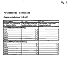
- Fig. 1 contains a table of measurement results of a pocket probe, which was arranged perpendicular to a glass surface with an output power of 15.5 mW. In this case, the measured powers are given in mW depending on the diameter of an optical fiber, taking into account the distance from the light source. It should be noted here that preferably a photosensitizer having a high concentration, preferably greater than 0.1%, in particular of the order of 1%, is used in a solvent, according to US Pat Fig. 1 is provided as a photosensitizer methylene blue in solution.
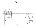
- Fig. 2 and 3 are shown as applicators a pocket probe and surface probe. It is understood that the dimensions given here by way of example as well as in the other figures can be modified in millimeters as required.
- the applicators contain a fiber optic cable 2, which is largely surrounded on the outside by a protective jacket 4.
- the applicators also have a connecting body 6, which is preferably designed as Luerstecker and via which the connection or recording takes place in the head of the irradiation device.
- the light guide 2 is passed through the connecting body 6 and projects beyond this according to the invention with its end 8 having a predetermined length, in accordance with Fig. 2 around 5 mm.
- the optical fiber end 8 is not provided with a protective sheath and is introduced and positioned in the head part of the irradiation device when coupling the applicator.
- the light guide 2 is at least partially flexible and / or includes a curved portion 10. Moreover, the dimensions of the applicators are predetermined such that they can be easily introduced into the oral cavity.
- the laser radiation occurs in the case of the laser used in both applicators with 1 mm core diameter due to the material properties and the geometry in the region of the tip 12 at a Divergenzwinkel of in the range of 30 to 60 °, preferably 40 to 55 degrees, to the frontal or in particular at the Pocketsonde in a range below 220 to 300 degrees, preferably 240 to 290 °, in particular 260 to 280 degrees circular from.
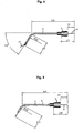
- the structure and the assembly of the application syringe 14, which contains the light-activatable substance in solution, are in 4 and 5 shown.
- the syringe 14 containing the photoactivatable substance in solution is supplied ready for use.
- the cap Before use, the cap must be removed from the tip by gentle rotation and the enclosed sterile cannula fixed on the Luer Lock adapter of the syringe. Pay attention to the correct finger position. The patient should be carefully informed before treatment.
- the outer packaging is opened, a blister containing the light-activatable substance, a blister with a cannula and, if appropriate, the instruction leaflet are removed. This is to be read before the first application.
- both blisters should be emptied over the sterile surgical tray.
- the syringe and cannula are therefore sterile and suitable for use in the sterile field.
- the silicone stopper is carefully removed from the syringe and the cannula is fixed by screwing it onto the luer cone.
- Fig. 6 shows the not yet bent light guide piece of the applicator without the connecting body, which is arranged in the region 16. Between this area 16 and the free end 18 of the protective jacket 4 is provided. At the free end 18, a spacer 20 is further arranged, by means of which a defined distance, in this case 5.5 mm, is given to the area to be treated.
- Fig. 7 shows the light guide piece for the pocket probe
- the free end 22 is free from the protective jacket 4 and has a length of 7 mm.
- the free end 22 is ground and has a surface corresponding to a machining with 100 grit sandpaper.
- the tip 24 of the free end 22 is formed blunt and / or provided with a radius.
- the surface preferably has a predetermined micro-roughness. This preferably has an Ra value in the range between 10 to 40 ⁇ m, preferably in the range between 20 to 30 ⁇ m.
- Fig. 8 shows an applicator similar Fig. 4 , wherein at the free end a spacer 20 is arranged.
- the optical fiber end 8 protrudes in this embodiment out of the connecting body 6, in this case in a length of 10 mm.
- Fig. 9 is similar to a bent fiber optic piece of a pocket probe Fig. 3 shown, wherein the free light guide end 8 protrudes from the connecting body 6 with a predetermined length, here 10 mm.
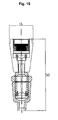
- FIG. 10 Side views of a preferred embodiment of the spacer 20 are shown.
- Fig. 11 shows partially in side views of the surface probe with shrunk light guide with the spacer 20th
- Fig. 12 and 13 show partially surface probes, according to Fig. 12 the area probe has a numerical aperture of 0.72.
- the optical system of the irradiation device is in Fig. 14 to 16 represented, according to Fig. 14 a beam divergence perpendicular to a maximum of 35 and according to Fig. 15 a beam divergence in parallel is specified by a maximum of 10 °.
- the laser diode 26 is arranged in a threaded sleeve 28. It is a multimode laser diode of 100 mW continuous for 670 nm including a monitor diode.
- a cone portion 30 is an objective lens 32, wherein a lens holder 34 is further provided for a further objective lens 36.
- an adjusting ring 38 and a receiving body 40 are provided.
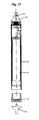
- Fig. 17 shows the irradiation device without the optical system, wherein in a housing tube 42, a battery tube 44 is provided for the batteries required for powering the electronics.
- a cap 46 is detachably connected via a threaded connection with the housing tube 42 and connectable.
- a key switch 48 is provided at the rear end of the housing tube 42 or the cap 46, by means of which the irradiation or laser device can be switched on or off.
- a head portion 60 is arranged, which is designed to receive the applicators and Lichtstrahlauskopplung through the central bore 52.
- Pocket probe spot probe radiation Radial range 250-280 degrees, especially substantially 270 degrees frontal Range 40-60 degrees, especially substantially 50 degrees frontal power density > 40mW / cm > 40mW / cm 2
- the preferred photoactivatable substance is a sterile, isotonic, deep blue, odorless aqueous liquid. It contains phenothiazine-5-ium, 3,7-bis (dimethylamino) chloride for coloring and sensitizing microorganisms for lethal photodynamic therapy in conjunction with the irradiation device.
- the osmolarity is approximately equal to that of human tissue.
- the solution in solution with the light-activatable substance is packed in a glass syringe and closed with a stopper made of silicone.
- the filling volume is 0.5 ml +/- 0.1 ml.
- the glass syringe is sealed to a blister and is steam-sterilized in a validated sterilization process.
- Said solution is suitably packed in five blisters with a leaflet in a carton. 5 needles 26G, which are also packed in a blister and sterilized, are included.
- the photoactivatable substance is used in the context of lethal photodynamic laser therapy for coloring and sensitizing microorganisms in local superficial infections, especially in the oral, maxillofacial and facial area. Subsequent exposure to the irradiation device eliminates colored microorganisms and restores the natural oral flora.
- the topical application was carried out in the area of infection without or with surgical opening and curettage and paralvessional in the following way: The patient rinsed with water twice for 20 seconds. Saliva or blood adhering to the surfaces to be treated is aspirated or dabbed to prevent dilution of the photoactive substance.
- the application of the light-activatable substance is started slowly, which is applied across the surface of the infected tissue areas by means of a syringe.
- the amount must be selected so that the light-activatable substance wets the surface of the infected areas as thinly as possible. Full wetting of niches and pockets in the fabric must be ensured. If necessary, with complex morphology, distribute carefully with the air blower.
- the reaction time of the light-activatable substance is at least 60 seconds. After flushing for at least 3 sec with simultaneous extraction of excess solution (it is essential to remove dye depots! With the irradiation unit. Essential for the germ-reducing effect and thus for the treatment result, is the correct dosage of the energy supply, the exposure.
- the therapy control by the practitioner contains the essential time for the determination of the necessary energy density (J / cm 2) the treatment time corresponding to the given treatment area. At least 1 minute exposure time with the irradiation device per cm 2 or per tooth must be observed.
- the selected dosimetry is summarized in the following table.
- irradiation is carried out at a distance of 0.55 cm and at a power density of 0.051 W / cm 2, a total dose of 3 J / cm 2 is used.
- bacteria are stained by light-activatable substances or vital dyes such as MB and irradiated with light of suitable wavelength, an effective phototoxic effect can be induced. Undyed cells show no toxic damage. Photochemical killings of potentially pathogenic bacteria are used in fur farms or zoological gardens by adding methylene blue to the drinking water.
- Oral administration may cause gastrointestinal discomfort and dysuria.
- Active ingredients and adjuvants 1 ml contains [mg] Methylene blue x 3 H2O 10.00 Trisodium citrate x 2 H2O 0.433 Citric acid x 1H2O 1.667 MHPC 10.00 sodium chloride 9.00 Water for injections 1000
- the substances used in the preparation are judged to be acceptable in terms of their biocompatibility, teratogenicity and mutagenicity under the given conditions of use with regard to the desired treatment objective.
- the photosensitizer PS
- PS photosensitizer
- the local concentration is also influenced by the fact that after local application of the PS usually increased salivation of the oral mucosa is induced. This leads to the reduction of the PS concentration and reduces the penetration of the dye into the lesion. In addition, salivary proteins can cause inactivation of the PS by non-specific binding.
- the excess PS is removed in order to increase the light transparency of the treated tissue.
- the irradiation area should always be greater than the area of the lesion.
- the light dose of about 100 J / cm 2 for PDT can be achieved in different ways: high power density and short exposure times or low power density and long exposure times. High powers are eliminated because of the mentioned thermal damage. On the other hand, if the power densities are too low, a photodynamic effect can not be achieved even with correspondingly long irradiation times.
- Methylene blue solutions are able to reduce the number of microorganisms tested in the respective culture media. Methylene blue solutions reduce almost all Gram-positive bacteria in vitro at a concentration of 25-44 ⁇ mol. The complete reduction of gram-negative bacteria requires 3 to 30 times higher concentrations. P. aeruginosa was reduced by 3.5 log 10 CFU at a concentration of 200 ⁇ mol and an energy density of 100 mW / cm 2 . The observed dark toxicity was greater for toluidine blue (TB) than for methylene blue (MB). This was consistent with the distribution coefficient P, which was determined to be 0.33 for TB and 0.11 for MB.
- both dyes are therefore hydrophilic, and should, at least theoretically, be able to pass through the water-filled porin protein channels of Gram-negative bacteria. While the dark toxicity for Gram-positive bacteria was hardly dependent on the type, the dark toxicity for Gram-negative bacteria was clearly dependent on the type, corresponding to the transmembrane permeability coefficient of the outer membrane of Gram-negative bacteria.
- the dark toxicity was dependent on both the concentration and the incubation time before irradiation.
- S. aureus was identified as the most resistant bacterium for the Gram-positive group, whose destruction required the highest concentrations.
- P. Aeruginosa was identified as the most resistant bacterium for the Gram-negative group, whose destruction required the highest concentrations.
- the photodynamic sensitivity depends on the transmembrane permeability and the hydrophilicity, the positive charge and the low molecular weight of the dye molecules favors the efficacy.
- the PDT is based on a photochemical process in which photosensitizers (PS) are activated by laser radiation and "fractionate" the irradiated energy so that it is available for the formation of locally toxic oxygen radicals.
- PS photosensitizers
- thermal damage to the tissue can be reliably ruled out.
- the clinical application of PDT is possible because the dye solutions selectively stain cell systems, on the other hand, the interaction with epithelium is very limited. Examinations on normal oral mucosa showed that the penetration depth of MB solutions after 10 min incubation time was limited only to the first 1-2 outer cell layers of the epithelium. Furthermore, the lifetime of the active radicals and their precursors is under microseconds, so that an expansion of the destructive effects into healthy tissue by diffusion is practically impossible, since the necessary time is not available.
- HELBO PocketProbe applicators it is possible according to the invention to have a substantially in the range from 1 to 7 J / cm 2 , preferably from 2 to 4 J / m 2 , in particular substantially uniform energy density of 3 J / cm 2 also in the complex Apply areas around and between teeth in the back of the oral cavity.
- the mentioned scattering effect is achieved on light emission or illumination on the area to be treated and on the other hand on the side of the applicator or light guide facing the laser device a collection effect is ensured such that a lens system is dispensable between the laser or the diode and the light guide.
- the device is powered by batteries or accumulators and uses as a light or beam source a semiconductor laser (laser diode), which is operated continuously (cw).
- Fig. 18 shows the irradiation or laser device from the side without applicator.
- the beam source is installed in a cylindrical, metal protective housing 42.
- the length of the protective housing containing the housing tube 42 is about 124 mm, the diameter about 16 mm.
- a contact cap 46 is screwed after inserting the batteries.
- the ready state is achieved by inserting the molded as a final cap key switch 48 in the contact cap 46.
- the operating state is indicated by differently colored LEDs 54.
- the head part 50 is screwed onto the protective housing 42 and glued to it, so that the direct access to the beam source is prevented.
- the head part 50 on the one hand serves to receive the applicators and thus the laser beam extraction, On the other hand, it includes the locking mechanism. By pressing a button 56 finally the semiconductor laser is activated.
- Fig. 19 shows two embodiments of applicators, wherein the imaged in the upper part of the applicator A is a pocket probe similar Fig. 2 while the applicator B shown in the lower part is similar to a surface probe Fig. 3 is.
- Both applicators consist of a transparent plastic fiber optic cable with a diameter of about 1 mm, have a Luer plug for receiving the head of the laser device, are bent and surrounded with a white protective sheath between Luerstecker and Strahlaustrittsende. The light conductor end (without protective sheath) at the Luer plug is inserted into the head of the protective housing.
- Applicator A has a slightly conical tip whose surface is roughened on the last 5 mm. The rough surface causes the laser light to be emitted in almost all spatial directions, with most of the energy being emitted in the axial direction of the light guide.
- Applicator B has a flat end face as an exit surface for the laser light.
- a wire loop is installed at the end of the optical fiber as a spacer.
- the laser light has a diverging, conical emission characteristic, which gives more energy in the axial direction. Applicator B was therefore used for all further measurements since it contains the greater potential danger from the point of view of laser safety.
- the in Fig. 20 illustrated locking mechanism includes a cross-sectionally "H” -shaped, rotationally symmetrical locking body 58 having a hole 60 in the middle with 1, 01 +0.02 mm in diameter.
- the laser diode In the recess of the "H's", which faces away from the beam exit, the laser diode is positioned and emits light in the activated state through the hole 60 in the locking body 58 in the direction of beam exit.
- a round locking disc 62 In the recess of the "H's", which faces the jet exit, there is a round locking disc 62, also with a hole located in the middle with 1, 01 +0.02 mm in diameter.
- the outer diameter of this disc 62 is substantially smaller than the inner diameter of the locking body 58, so according to Fig. 20 the disk can be moved in the recess.
- the locking disc is held by means of a wire spring (locking spring) acentric.
- this disc 62 covers the hole of the lock body off and the laser light can not escape.
- the wire spring 64 is guided in a groove on the circumference of the locking disc. How out Fig. 21 and the exploded view according to Fig.
- the locking body 58 in the recess of which the locking letter is movably arranged, is arranged in a diode holder 68.
- the two mentioned holes of the locking body 58 and the locking disc 62 are clearly visible.
- the wire spring 64 pushes the locking disk 62 back to the home position and the laser light is blocked.
- other return elements may be provided in the invention, to allow the exit of laser light only when the applicator and in particular its optical fiber end is properly connected to the irradiation device.
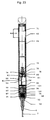
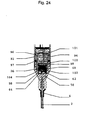
- Fig. 23 shows a section through the irradiation device and Fig. 24 shows enlarged the front part.
- This irradiation device basically corresponds to the one already explained above and additionally contains the locking device or the locking mechanism.
- three batteries 70 are arranged, which are acted upon by means of a battery spring 72.
- a spacer 80 are present for contacting a female connector 74 is disposed in a bushing guide 76, further comprising a disc 78.
- two plug pins 82, 83 are provided for contacting with an electronics or electronic board 84.
- On the electronic board 84 of the externally operable button 56 is arranged, in particular for sealing a button film 86 are provided together with a ball 88.
- an area with a firing pin 92 is provided, further comprising a front insulation 94 is present.
- two O-rings 96, 97 are further arranged.
- the head part 60 is arranged, whose front end engages in the connecting body or Luerstecker 4 of the applicator not shown here.
- the laser diode 26 is provided to the rear of the battery tube 44 towards an insulating 98 and a print 100 for the diode including required for contacting wires.
- a protective film 102 is provided in the radiation direction in front of the laser diode, by means of which, preferably, the laser diode against external Actions is protected, with an additional O-ring 104 is provided. Furthermore, the already explained locking body 58, the locking disc 62 and the locking spring 64 are arranged in the inner recess of the head part 50.
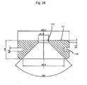
- Fig. 25 shows a section in an axial sectional plane through the locking body 58, wherein the H-shaped cross-sectional area is clearly visible. It is understood that the specified dimensions for the particular design in millimeters can also be specified differently.
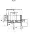
- Fig. 26 is a section in an axial sectional plane through the locking disc 62 is shown, which contains the aforementioned hole 106 in the middle on the outer circumference, the locking disc has a groove 108, in which engages the wire or locking spring.
- the diode is inserted in the diode holder and fixed with the ESD board from behind.
- the diode is now in the diode holder.
- the diode is aligned over the inner diameter of the diode holder.
- the lock holder can be pushed onto the diode.
- the lock holder is positioned over the inside diameter of the diode holder.
- the O-ring in the lock holder absorbs light bumps in the longitudinal direction.
- the locking spring is inserted into the groove of the locking plate. This arrangement is inserted in the opening of the lock holder. The head is pushed over the lock holder and the diode holder.
- the light guide is inserted through the 1.5 mm hole of the head in the light guide. After approx. 7mm, the optical fiber is positioned over a reduction of the diameter to 1.1 mm.
- the light guide is then advanced to the locking pad.
- the locking plate is pressed by the bias of the spring on the inner edge of the locking bracket. The plate is thus always decentered and covers the 1.01 mm bore of the lock holder, thus no radiation can escape.
- the light guide strikes the cone of the locking plate and presses it against the spring force into the middle of the locking holder. After centering the lock pad, the 1.01 mm bore of the lock holder is released and the light guide is advanced through this opening into the docking area.
- the light guide has reached the coupling area when the luer plug has reached the stop on the head.
- the locking spring pushes the plate back into the decentralized position, which closes the 1.01 mm hole again.
- the spring wire of the locking spring has a diameter of 0.25mm.
- the groove has 0.3 mm. Since the wire has a round shape, it can not jam in the groove. This will secure the locking device.
- the edges of the locking plate are broken by sliding grinding to 0.2 mm.
- the spring always presses the locking plate outward. Due to the position of the laser during operation, locking is provided even without a locking spring.
- the latch plate is pulled down by its weight, closing the 1.01 mm bore. Due to the special shape of the spring, a spring out of the groove can also be excluded. The spring shape encloses the locking plate and thus secures it.
- a tilt of the plate has no effect on the locking mechanism by the small angle.
- the tile aligns with its next position in the next fiber optic slot.
- Dirt on the locking mechanism have no influence on the function of the lock. It is only to be expected with abrasion dust of the light guide. Due to the flexible design of the light guide is expected only with low abrasion. At the annual review, a cleaning of the mechanism can be easily done. Foreign bodies can only occur in the size of 1.1 mm, as this size is limited by the feedthrough bore in the head.
- Eventual decrease of the spring force is checked by tests. Changes due to falling on the ground are also measured.
Priority Applications (2)
| Application Number | Priority Date | Filing Date | Title |
|---|---|---|---|
| PL10003440T PL2204218T3 (pl) | 2003-05-28 | 2004-05-27 | Układ do redukcji mikroorganizmów |
| SI200431863T SI2204218T1 (sl) | 2003-05-28 | 2004-05-27 | Razmestitev za reduciranje mikroorganizmov |
Applications Claiming Priority (3)
| Application Number | Priority Date | Filing Date | Title |
|---|---|---|---|
| DE10324644 | 2003-05-28 | ||
| DE10349710A DE10349710A1 (de) | 2003-05-28 | 2003-10-23 | Anordnung zur Reduktion von Mikroorganismen |
| EP04739394A EP1626777B1 (fr) | 2003-05-28 | 2004-05-27 | Dispositif permettant de reduire le nombre de micro-organismes |
Related Parent Applications (2)
| Application Number | Title | Priority Date | Filing Date |
|---|---|---|---|
| EP04739394.7 Division | 2004-05-27 | ||
| EP04739394A Division-Into EP1626777B1 (fr) | 2003-05-28 | 2004-05-27 | Dispositif permettant de reduire le nombre de micro-organismes |
Publications (2)
| Publication Number | Publication Date |
|---|---|
| EP2204218A1 true EP2204218A1 (fr) | 2010-07-07 |
| EP2204218B1 EP2204218B1 (fr) | 2012-01-25 |
Family
ID=33491652
Family Applications (2)
| Application Number | Title | Priority Date | Filing Date |
|---|---|---|---|
| EP10003440A Active EP2204218B1 (fr) | 2003-05-28 | 2004-05-27 | Agencement de réduction de microorganismes |
| EP04739394A Active EP1626777B1 (fr) | 2003-05-28 | 2004-05-27 | Dispositif permettant de reduire le nombre de micro-organismes |
Family Applications After (1)
| Application Number | Title | Priority Date | Filing Date |
|---|---|---|---|
| EP04739394A Active EP1626777B1 (fr) | 2003-05-28 | 2004-05-27 | Dispositif permettant de reduire le nombre de micro-organismes |
Country Status (11)
| Country | Link |
|---|---|
| US (2) | US8486123B2 (fr) |
| EP (2) | EP2204218B1 (fr) |
| JP (1) | JP4560516B2 (fr) |
| KR (1) | KR101169349B1 (fr) |
| AT (1) | ATE542568T1 (fr) |
| DE (1) | DE10349710A1 (fr) |
| DK (2) | DK1626777T3 (fr) |
| ES (2) | ES2380444T3 (fr) |
| PL (2) | PL2204218T3 (fr) |
| SI (2) | SI2204218T1 (fr) |
| WO (1) | WO2004105874A2 (fr) |
Families Citing this family (18)
| Publication number | Priority date | Publication date | Assignee | Title |
|---|---|---|---|---|
| US9192780B2 (en) * | 1998-11-30 | 2015-11-24 | L'oreal | Low intensity light therapy for treatment of retinal, macular, and visual pathway disorders |
| US6283956B1 (en) | 1998-11-30 | 2001-09-04 | David H. McDaniels | Reduction, elimination, or stimulation of hair growth |
| US6887260B1 (en) | 1998-11-30 | 2005-05-03 | Light Bioscience, Llc | Method and apparatus for acne treatment |
| US20060212025A1 (en) | 1998-11-30 | 2006-09-21 | Light Bioscience, Llc | Method and apparatus for acne treatment |
| EP1617777A4 (fr) | 2003-04-10 | 2010-11-03 | Gentlewaves Llc | Procedes de photomodulation et dispositifs de regulation de la proliferation cellulaire et de l'expression genetique |
| CA2533129A1 (fr) | 2003-07-31 | 2005-02-10 | Light Bioscience, Llc | Systeme et methode de traitement photodynamique de brulures, blessures et troubles cutanes correspondant |
| DE202006016025U1 (de) * | 2006-10-16 | 2007-02-08 | Arentz, Jochen, Dr.med.dent. | Vorrichtung zur antibakteriellen Behandlung eines Patienten |
| GB0704982D0 (en) * | 2007-03-15 | 2007-04-25 | Denfotex Ltd | Improvements in or relating to photodynamic therapy |
| CA2692895A1 (fr) * | 2007-06-29 | 2009-01-08 | Alplight | Dispositif de radiation portable |
| JP5650730B2 (ja) | 2009-06-09 | 2015-01-07 | ブレーデント・メデイカル・ゲー・エム・ベー・ハー・ウント・コー・カー・ゲー | 光線力学的治療のための装置および方法 |
| JP2015012887A (ja) * | 2013-07-03 | 2015-01-22 | 株式会社エーゼット | 歯科治療装置 |
| EP3307129A1 (fr) | 2015-06-11 | 2018-04-18 | The Procter and Gamble Company | Dispositif et procédés pour l'application de compositions sur des surfaces |
| CN111701144B (zh) | 2015-07-28 | 2023-03-21 | 诺欧生物有限责任公司 | 用于对一氧化氮的光疗调节的系统和方法 |
| DE102016106532A1 (de) * | 2016-04-08 | 2017-10-12 | Bredent Medical Gmbh & Co. Kg | Applikator zur photodynamischen Therapie |
| US11147984B2 (en) | 2020-03-19 | 2021-10-19 | Know Bio, Llc | Illumination devices for inducing biological effects |
| US11654294B2 (en) | 2021-03-15 | 2023-05-23 | Know Bio, Llc | Intranasal illumination devices |
| US20230099922A1 (en) * | 2021-09-24 | 2023-03-30 | Oral IQ LLC | LED Therapeutic Device |
| US20230330431A1 (en) * | 2022-04-15 | 2023-10-19 | Luminance Medical Ventures Incorporated | Phototherapy |
Citations (7)
| Publication number | Priority date | Publication date | Assignee | Title |
|---|---|---|---|---|
| US4785805A (en) | 1985-05-28 | 1988-11-22 | Surgical Laser Technologies, Inc. | Two-piece disposable laser delivery system |
| DE3918965A1 (de) | 1989-01-11 | 1990-07-12 | Masahiko Hoshino | Lasergeraet fuer medizinische behandlung |
| US5029581A (en) | 1986-11-19 | 1991-07-09 | Fuji Electric Co., Ltd. | Laser therapeutic apparatus |
| US5454794A (en) | 1993-10-15 | 1995-10-03 | Pdt Systems, Inc. | Steerable light diffusing catheter |
| JPH11155638A (ja) * | 1997-11-26 | 1999-06-15 | Yasuhiro Tsuboi | 紫外線発生歯ブラシ |
| WO2001087416A1 (fr) | 2000-05-17 | 2001-11-22 | Kent Crossley | Procede et dispositif servant a empecher des infections |
| DE10049999A1 (de) | 2000-10-10 | 2002-04-11 | Heiko Weiser | Apparat zur Photodynamischen Therapie und Diagnostik |
Family Cites Families (18)
| Publication number | Priority date | Publication date | Assignee | Title |
|---|---|---|---|---|
| US4754328A (en) * | 1984-01-03 | 1988-06-28 | Medical Dynamics, Inc. | Laser endoscope |
| US5116329A (en) * | 1988-10-20 | 1992-05-26 | Pfizer Hospital Products Groups, Inc. | Medical laser interconnect system |
| AU6931191A (en) | 1990-01-12 | 1991-08-01 | Laserscope | Means for inserting instrumentation for a percutaneous diskectomy using a laser |
| US5242439A (en) | 1990-01-12 | 1993-09-07 | Laserscope | Means for inserting instrumentation for a percutaneous diskectomy using a laser |
| JPH0715554Y2 (ja) * | 1991-06-07 | 1995-04-12 | 株式会社モリタ製作所 | ファイバー式レーザ治療装置 |
| ATE159661T1 (de) | 1992-04-30 | 1997-11-15 | Eastman Dental Inst | Medikament zur desinfektion der mundhöhle |
| US5445608A (en) | 1993-08-16 | 1995-08-29 | James C. Chen | Method and apparatus for providing light-activated therapy |
| JP3551996B2 (ja) | 1995-08-25 | 2004-08-11 | 松下電器産業株式会社 | 医療用レーザプローブ |
| JPH10127579A (ja) | 1996-11-02 | 1998-05-19 | Takeshi Okada | 喉頭鏡 |
| US6411852B1 (en) | 1997-04-07 | 2002-06-25 | Broncus Technologies, Inc. | Modification of airways by application of energy |
| JPH10328197A (ja) * | 1997-06-04 | 1998-12-15 | Morita Mfg Co Ltd | レーザ医療装置およびこれに用いるレーザプローブ |
| US5951543A (en) | 1997-06-30 | 1999-09-14 | Clinicon Corporation | Delivery system and method for surgical laser |
| JPH11244295A (ja) | 1998-03-02 | 1999-09-14 | Osada Res Inst Ltd | 医科用コードレス半導体レーザ装置 |
| RU2145247C1 (ru) * | 1998-04-10 | 2000-02-10 | Жаров Владимир Павлович | Фотоматричное терапевтическое устройство для лечения протяженных патологий |
| DE19852948C2 (de) * | 1998-11-12 | 2002-07-18 | Asclepion Meditec Ag | Dermatologisches Handstück |
| JP2001017556A (ja) | 1999-07-08 | 2001-01-23 | Katsufumi Ito | レーザ光線照射装置 |
| US6969253B2 (en) * | 1999-09-24 | 2005-11-29 | Cao Group, Inc. | Light for use in activating light-activated materials, the light having at least one light emitting semiconductor chip, the chip being attached to a primary heat sink that is attached to a secondary heat sink using heat conductive and electrically insulative adhesive |
| US6366719B1 (en) | 2000-08-17 | 2002-04-02 | Miravant Systems, Inc. | Photodynamic therapy light diffuser |
-
2003
- 2003-10-23 DE DE10349710A patent/DE10349710A1/de not_active Withdrawn
-
2004
- 2004-05-27 EP EP10003440A patent/EP2204218B1/fr active Active
- 2004-05-27 JP JP2006529934A patent/JP4560516B2/ja not_active Expired - Fee Related
- 2004-05-27 KR KR1020057022665A patent/KR101169349B1/ko not_active IP Right Cessation
- 2004-05-27 PL PL10003440T patent/PL2204218T3/pl unknown
- 2004-05-27 PL PL04739394T patent/PL1626777T3/pl unknown
- 2004-05-27 SI SI200431863T patent/SI2204218T1/sl unknown
- 2004-05-27 ES ES10003440T patent/ES2380444T3/es active Active
- 2004-05-27 DK DK04739394.7T patent/DK1626777T3/da active
- 2004-05-27 ES ES04739394T patent/ES2397065T3/es active Active
- 2004-05-27 WO PCT/EP2004/005719 patent/WO2004105874A2/fr active Application Filing
- 2004-05-27 SI SI200431977T patent/SI1626777T1/sl unknown
- 2004-05-27 US US10/558,453 patent/US8486123B2/en not_active Expired - Fee Related
- 2004-05-27 DK DK10003440.4T patent/DK2204218T3/da active
- 2004-05-27 EP EP04739394A patent/EP1626777B1/fr active Active
- 2004-05-27 AT AT10003440T patent/ATE542568T1/de active
-
2013
- 2013-06-11 US US13/915,156 patent/US20130274833A1/en not_active Abandoned
Patent Citations (7)
| Publication number | Priority date | Publication date | Assignee | Title |
|---|---|---|---|---|
| US4785805A (en) | 1985-05-28 | 1988-11-22 | Surgical Laser Technologies, Inc. | Two-piece disposable laser delivery system |
| US5029581A (en) | 1986-11-19 | 1991-07-09 | Fuji Electric Co., Ltd. | Laser therapeutic apparatus |
| DE3918965A1 (de) | 1989-01-11 | 1990-07-12 | Masahiko Hoshino | Lasergeraet fuer medizinische behandlung |
| US5454794A (en) | 1993-10-15 | 1995-10-03 | Pdt Systems, Inc. | Steerable light diffusing catheter |
| JPH11155638A (ja) * | 1997-11-26 | 1999-06-15 | Yasuhiro Tsuboi | 紫外線発生歯ブラシ |
| WO2001087416A1 (fr) | 2000-05-17 | 2001-11-22 | Kent Crossley | Procede et dispositif servant a empecher des infections |
| DE10049999A1 (de) | 2000-10-10 | 2002-04-11 | Heiko Weiser | Apparat zur Photodynamischen Therapie und Diagnostik |
Also Published As
| Publication number | Publication date |
|---|---|
| EP1626777B1 (fr) | 2012-10-03 |
| KR20060024780A (ko) | 2006-03-17 |
| ES2380444T3 (es) | 2012-05-11 |
| DE10349710A1 (de) | 2004-12-16 |
| JP2007521108A (ja) | 2007-08-02 |
| JP4560516B2 (ja) | 2010-10-13 |
| KR101169349B1 (ko) | 2012-07-30 |
| SI2204218T1 (sl) | 2012-06-29 |
| PL1626777T3 (pl) | 2013-03-29 |
| DK2204218T3 (da) | 2012-04-23 |
| ES2397065T3 (es) | 2013-03-04 |
| US20130274833A1 (en) | 2013-10-17 |
| SI1626777T1 (sl) | 2013-02-28 |
| EP2204218B1 (fr) | 2012-01-25 |
| WO2004105874A2 (fr) | 2004-12-09 |
| WO2004105874A3 (fr) | 2005-02-03 |
| US20080051856A1 (en) | 2008-02-28 |
| ATE542568T1 (de) | 2012-02-15 |
| US8486123B2 (en) | 2013-07-16 |
| EP1626777A2 (fr) | 2006-02-22 |
| PL2204218T3 (pl) | 2012-07-31 |
| DK1626777T3 (da) | 2013-01-07 |
Similar Documents
| Publication | Publication Date | Title |
|---|---|---|
| EP1626777B1 (fr) | Dispositif permettant de reduire le nombre de micro-organismes | |
| EP1087794B1 (fr) | Dispositif d'application de lumiere pour le diagnostic ou la therapie photodynamiques d'affections du parodonte et des dents | |
| Parker | The use of diffuse laser photonic energy and indocyanine green photosensitiser as an adjunct to periodontal therapy | |
| EP1819360A1 (fr) | Methode de traitement photodynamique des micro-organismes dans la cavite buccale mettant en oeuvre une source de lumiere non coherente | |
| Dave et al. | Photodynamic therapy: A view through light | |
| US10136963B2 (en) | System and method for introducing photosensitive dyes via an insert into a root canal in a tooth, method for producing said dye impregnated insert and method of using said dye-impregnated insert | |
| AU2004241781B2 (en) | Photo-activated disinfection | |
| DE102010050962A1 (de) | Optisches Gerät zur therapeutischen oder kosmetischen Behandlung | |
| US20220296713A1 (en) | Biophotonic compositions for treating skin and soft tissue wounds having either or both non-resistant and resistant infections | |
| US20220125922A1 (en) | Photosensitive Dyes and Method of Using Said Dyes | |
| EP3700461B1 (fr) | Appareil portatif permettant l'excitation de fluorescence et l'irradiation de micro-organismes dans la bouche et la gorge | |
| EP1993534A1 (fr) | Utilisation de vert d'indocyanine photoactivé pour le traitement de pathologies inflammatoires de la cavité buccale | |
| US20120172408A1 (en) | Active ingredient comprising indocyanine green and/or infracyanine green | |
| US20210353754A1 (en) | Pigment for antimicrobial photodynamic therapy | |
| DE102022118867A1 (de) | Gerät und Zusammensetzung zur Behandlung einer Wunde, Kartusche für das Gerät, Verfahren zur Herstellung der Zusammensetzung | |
| Rajab et al. | Use of Single Dose 940 nm diode Laser to Relief Facial Pain | |
| KR100564897B1 (ko) | 광감작제와 케미컬 라이트를 이용한 광역학 치료법 |
Legal Events
| Date | Code | Title | Description |
|---|---|---|---|
| PUAI | Public reference made under article 153(3) epc to a published international application that has entered the european phase |
Free format text: ORIGINAL CODE: 0009012 |
|
| AC | Divisional application: reference to earlier application |
Ref document number: 1626777 Country of ref document: EP Kind code of ref document: P |
|
| AK | Designated contracting states |
Kind code of ref document: A1 Designated state(s): AT BE BG CH CY CZ DE DK EE ES FI FR GB GR HU IE IT LI LU MC NL PL PT RO SE SI SK TR |
|
| 17P | Request for examination filed |
Effective date: 20110104 |
|
| GRAP | Despatch of communication of intention to grant a patent |
Free format text: ORIGINAL CODE: EPIDOSNIGR1 |
|
| GRAS | Grant fee paid |
Free format text: ORIGINAL CODE: EPIDOSNIGR3 |
|
| GRAA | (expected) grant |
Free format text: ORIGINAL CODE: 0009210 |
|
| RAP1 | Party data changed (applicant data changed or rights of an application transferred) |
Owner name: BREDENT MEDICAL GMBH & CO. KG |
|
| AC | Divisional application: reference to earlier application |
Ref document number: 1626777 Country of ref document: EP Kind code of ref document: P |
|
| AK | Designated contracting states |
Kind code of ref document: B1 Designated state(s): AT BE BG CH CY CZ DE DK EE ES FI FR GB GR HU IE IT LI LU MC NL PL PT RO SE SI SK TR |
|
| REG | Reference to a national code |
Ref country code: GB Ref legal event code: FG4D Free format text: NOT ENGLISH |
|
| REG | Reference to a national code |
Ref country code: CH Ref legal event code: EP |
|
| REG | Reference to a national code |
Ref country code: AT Ref legal event code: REF Ref document number: 542568 Country of ref document: AT Kind code of ref document: T Effective date: 20120215 |
|
| REG | Reference to a national code |
Ref country code: IE Ref legal event code: FG4D |
|
| REG | Reference to a national code |
Ref country code: DE Ref legal event code: R096 Ref document number: 502004013267 Country of ref document: DE Effective date: 20120322 |
|
| REG | Reference to a national code |
Ref country code: NL Ref legal event code: T3 |
|
| REG | Reference to a national code |
Ref country code: DK Ref legal event code: T3 |
|
| REG | Reference to a national code |
Ref country code: SE Ref legal event code: TRGR |
|
| REG | Reference to a national code |
Ref country code: ES Ref legal event code: FG2A Ref document number: 2380444 Country of ref document: ES Kind code of ref document: T3 Effective date: 20120511 |
|
| REG | Reference to a national code |
Ref country code: GR Ref legal event code: EP Ref document number: 20120400774 Country of ref document: GR Effective date: 20120518 |
|
| REG | Reference to a national code |
Ref country code: PL Ref legal event code: T3 |
|
| REG | Reference to a national code |
Ref country code: IE Ref legal event code: FD4D |
|
| PG25 | Lapsed in a contracting state [announced via postgrant information from national office to epo] |
Ref country code: PT Free format text: LAPSE BECAUSE OF FAILURE TO SUBMIT A TRANSLATION OF THE DESCRIPTION OR TO PAY THE FEE WITHIN THE PRESCRIBED TIME-LIMIT Effective date: 20120525 |
|
| PG25 | Lapsed in a contracting state [announced via postgrant information from national office to epo] |
Ref country code: CY Free format text: LAPSE BECAUSE OF FAILURE TO SUBMIT A TRANSLATION OF THE DESCRIPTION OR TO PAY THE FEE WITHIN THE PRESCRIBED TIME-LIMIT Effective date: 20120125 |
|
| PG25 | Lapsed in a contracting state [announced via postgrant information from national office to epo] |
Ref country code: RO Free format text: LAPSE BECAUSE OF FAILURE TO SUBMIT A TRANSLATION OF THE DESCRIPTION OR TO PAY THE FEE WITHIN THE PRESCRIBED TIME-LIMIT Effective date: 20120125 Ref country code: CZ Free format text: LAPSE BECAUSE OF FAILURE TO SUBMIT A TRANSLATION OF THE DESCRIPTION OR TO PAY THE FEE WITHIN THE PRESCRIBED TIME-LIMIT Effective date: 20120125 Ref country code: EE Free format text: LAPSE BECAUSE OF FAILURE TO SUBMIT A TRANSLATION OF THE DESCRIPTION OR TO PAY THE FEE WITHIN THE PRESCRIBED TIME-LIMIT Effective date: 20120125 Ref country code: IE Free format text: LAPSE BECAUSE OF FAILURE TO SUBMIT A TRANSLATION OF THE DESCRIPTION OR TO PAY THE FEE WITHIN THE PRESCRIBED TIME-LIMIT Effective date: 20120125 |
|
| PG25 | Lapsed in a contracting state [announced via postgrant information from national office to epo] |
Ref country code: SK Free format text: LAPSE BECAUSE OF FAILURE TO SUBMIT A TRANSLATION OF THE DESCRIPTION OR TO PAY THE FEE WITHIN THE PRESCRIBED TIME-LIMIT Effective date: 20120125 |
|
| PLBE | No opposition filed within time limit |
Free format text: ORIGINAL CODE: 0009261 |
|
| STAA | Information on the status of an ep patent application or granted ep patent |
Free format text: STATUS: NO OPPOSITION FILED WITHIN TIME LIMIT |
|
| PG25 | Lapsed in a contracting state [announced via postgrant information from national office to epo] |
Ref country code: MC Free format text: LAPSE BECAUSE OF NON-PAYMENT OF DUE FEES Effective date: 20120531 |
|
| 26N | No opposition filed |
Effective date: 20121026 |
|
| REG | Reference to a national code |
Ref country code: DE Ref legal event code: R097 Ref document number: 502004013267 Country of ref document: DE Effective date: 20121026 |
|
| PG25 | Lapsed in a contracting state [announced via postgrant information from national office to epo] |
Ref country code: LU Free format text: LAPSE BECAUSE OF NON-PAYMENT OF DUE FEES Effective date: 20120527 |
|
| PG25 | Lapsed in a contracting state [announced via postgrant information from national office to epo] |
Ref country code: HU Free format text: LAPSE BECAUSE OF FAILURE TO SUBMIT A TRANSLATION OF THE DESCRIPTION OR TO PAY THE FEE WITHIN THE PRESCRIBED TIME-LIMIT Effective date: 20040527 |
|
| REG | Reference to a national code |
Ref country code: DE Ref legal event code: R082 Ref document number: 502004013267 Country of ref document: DE Representative=s name: BAUR & WEBER PATENTANWAELTE PARTG MBB, DE Ref country code: DE Ref legal event code: R082 Ref document number: 502004013267 Country of ref document: DE Representative=s name: BAUR & WEBER PATENTANWAELTE, DE |
|
| REG | Reference to a national code |
Ref country code: FR Ref legal event code: PLFP Year of fee payment: 13 |
|
| PGFP | Annual fee paid to national office [announced via postgrant information from national office to epo] |
Ref country code: NL Payment date: 20160523 Year of fee payment: 13 |
|
| PGFP | Annual fee paid to national office [announced via postgrant information from national office to epo] |
Ref country code: FI Payment date: 20160519 Year of fee payment: 13 Ref country code: BG Payment date: 20160520 Year of fee payment: 13 Ref country code: GB Payment date: 20160523 Year of fee payment: 13 Ref country code: CH Payment date: 20160526 Year of fee payment: 13 Ref country code: GR Payment date: 20160523 Year of fee payment: 13 |
|
| PGFP | Annual fee paid to national office [announced via postgrant information from national office to epo] |
Ref country code: BE Payment date: 20160523 Year of fee payment: 13 Ref country code: PL Payment date: 20160516 Year of fee payment: 13 Ref country code: DK Payment date: 20160523 Year of fee payment: 13 Ref country code: SI Payment date: 20160518 Year of fee payment: 13 Ref country code: TR Payment date: 20160517 Year of fee payment: 13 Ref country code: SE Payment date: 20160523 Year of fee payment: 13 |
|
| REG | Reference to a national code |
Ref country code: FR Ref legal event code: PLFP Year of fee payment: 14 |
|
| REG | Reference to a national code |
Ref country code: CH Ref legal event code: PL |
|
| REG | Reference to a national code |
Ref country code: SE Ref legal event code: EUG Ref country code: DK Ref legal event code: EBP Effective date: 20170531 |
|
| REG | Reference to a national code |
Ref country code: NL Ref legal event code: MM Effective date: 20170601 |
|
| GBPC | Gb: european patent ceased through non-payment of renewal fee |
Effective date: 20170527 |
|
| PG25 | Lapsed in a contracting state [announced via postgrant information from national office to epo] |
Ref country code: FI Free format text: LAPSE BECAUSE OF NON-PAYMENT OF DUE FEES Effective date: 20170527 |
|
| PG25 | Lapsed in a contracting state [announced via postgrant information from national office to epo] |
Ref country code: SI Free format text: LAPSE BECAUSE OF NON-PAYMENT OF DUE FEES Effective date: 20170528 Ref country code: GR Free format text: LAPSE BECAUSE OF NON-PAYMENT OF DUE FEES Effective date: 20171206 Ref country code: SE Free format text: LAPSE BECAUSE OF NON-PAYMENT OF DUE FEES Effective date: 20170528 Ref country code: CH Free format text: LAPSE BECAUSE OF NON-PAYMENT OF DUE FEES Effective date: 20170531 Ref country code: LI Free format text: LAPSE BECAUSE OF NON-PAYMENT OF DUE FEES Effective date: 20170531 |
|
| REG | Reference to a national code |
Ref country code: SI Ref legal event code: KO00 Effective date: 20180111 |
|
| PG25 | Lapsed in a contracting state [announced via postgrant information from national office to epo] |
Ref country code: NL Free format text: LAPSE BECAUSE OF NON-PAYMENT OF DUE FEES Effective date: 20170601 |
|
| REG | Reference to a national code |
Ref country code: BE Ref legal event code: MM Effective date: 20170531 |
|
| PG25 | Lapsed in a contracting state [announced via postgrant information from national office to epo] |
Ref country code: DK Free format text: LAPSE BECAUSE OF NON-PAYMENT OF DUE FEES Effective date: 20170531 Ref country code: GB Free format text: LAPSE BECAUSE OF NON-PAYMENT OF DUE FEES Effective date: 20170527 |
|
| REG | Reference to a national code |
Ref country code: FR Ref legal event code: PLFP Year of fee payment: 15 |
|
| PGFP | Annual fee paid to national office [announced via postgrant information from national office to epo] |
Ref country code: ES Payment date: 20180626 Year of fee payment: 15 |
|
| PG25 | Lapsed in a contracting state [announced via postgrant information from national office to epo] |
Ref country code: BE Free format text: LAPSE BECAUSE OF NON-PAYMENT OF DUE FEES Effective date: 20170531 |
|
| PGFP | Annual fee paid to national office [announced via postgrant information from national office to epo] |
Ref country code: IT Payment date: 20180518 Year of fee payment: 15 Ref country code: AT Payment date: 20180517 Year of fee payment: 15 Ref country code: FR Payment date: 20180523 Year of fee payment: 15 |
|
| PG25 | Lapsed in a contracting state [announced via postgrant information from national office to epo] |
Ref country code: PL Free format text: LAPSE BECAUSE OF NON-PAYMENT OF DUE FEES Effective date: 20170527 |
|
| PG25 | Lapsed in a contracting state [announced via postgrant information from national office to epo] |
Ref country code: BG Free format text: LAPSE BECAUSE OF NON-PAYMENT OF DUE FEES Effective date: 20171206 |
|
| REG | Reference to a national code |
Ref country code: AT Ref legal event code: MM01 Ref document number: 542568 Country of ref document: AT Kind code of ref document: T Effective date: 20190527 |
|
| PG25 | Lapsed in a contracting state [announced via postgrant information from national office to epo] |
Ref country code: AT Free format text: LAPSE BECAUSE OF NON-PAYMENT OF DUE FEES Effective date: 20190527 |
|
| PG25 | Lapsed in a contracting state [announced via postgrant information from national office to epo] |
Ref country code: IT Free format text: LAPSE BECAUSE OF NON-PAYMENT OF DUE FEES Effective date: 20190527 |
|
| PG25 | Lapsed in a contracting state [announced via postgrant information from national office to epo] |
Ref country code: FR Free format text: LAPSE BECAUSE OF NON-PAYMENT OF DUE FEES Effective date: 20190531 |
|
| REG | Reference to a national code |
Ref country code: ES Ref legal event code: FD2A Effective date: 20200930 |
|
| PG25 | Lapsed in a contracting state [announced via postgrant information from national office to epo] |
Ref country code: ES Free format text: LAPSE BECAUSE OF NON-PAYMENT OF DUE FEES Effective date: 20190528 |
|
| PG25 | Lapsed in a contracting state [announced via postgrant information from national office to epo] |
Ref country code: TR Free format text: LAPSE BECAUSE OF NON-PAYMENT OF DUE FEES Effective date: 20170527 |
|
| PGFP | Annual fee paid to national office [announced via postgrant information from national office to epo] |
Ref country code: DE Payment date: 20230531 Year of fee payment: 20 |