EP2204208B1 - Deflectable sheath introducer - Google Patents
Deflectable sheath introducer Download PDFInfo
- Publication number
- EP2204208B1 EP2204208B1 EP09252919.7A EP09252919A EP2204208B1 EP 2204208 B1 EP2204208 B1 EP 2204208B1 EP 09252919 A EP09252919 A EP 09252919A EP 2204208 B1 EP2204208 B1 EP 2204208B1
- Authority
- EP
- European Patent Office
- Prior art keywords
- shaft
- introducer
- deflection
- tensile
- distal
- Prior art date
- Legal status (The legal status is an assumption and is not a legal conclusion. Google has not performed a legal analysis and makes no representation as to the accuracy of the status listed.)
- Active
Links
- 239000000835 fiber Substances 0.000 claims description 20
- 238000004873 anchoring Methods 0.000 claims description 3
- 239000000463 material Substances 0.000 description 12
- 238000000034 method Methods 0.000 description 11
- 230000015572 biosynthetic process Effects 0.000 description 9
- 238000005755 formation reaction Methods 0.000 description 9
- 230000007704 transition Effects 0.000 description 9
- 210000002216 heart Anatomy 0.000 description 6
- 238000003780 insertion Methods 0.000 description 6
- 230000037431 insertion Effects 0.000 description 6
- 239000012530 fluid Substances 0.000 description 5
- 238000010276 construction Methods 0.000 description 4
- 230000002457 bidirectional effect Effects 0.000 description 3
- 239000003292 glue Substances 0.000 description 3
- 238000003475 lamination Methods 0.000 description 3
- 238000000465 moulding Methods 0.000 description 3
- 210000003462 vein Anatomy 0.000 description 3
- 238000003466 welding Methods 0.000 description 3
- 241000237858 Gastropoda Species 0.000 description 2
- 229920002614 Polyether block amide Polymers 0.000 description 2
- 239000004809 Teflon Substances 0.000 description 2
- 229920006362 Teflon® Polymers 0.000 description 2
- 239000000853 adhesive Substances 0.000 description 2
- 230000001070 adhesive effect Effects 0.000 description 2
- 238000005452 bending Methods 0.000 description 2
- 230000008901 benefit Effects 0.000 description 2
- 239000008280 blood Substances 0.000 description 2
- 210000004369 blood Anatomy 0.000 description 2
- 239000011248 coating agent Substances 0.000 description 2
- 238000000576 coating method Methods 0.000 description 2
- 230000006835 compression Effects 0.000 description 2
- 238000007906 compression Methods 0.000 description 2
- 230000000694 effects Effects 0.000 description 2
- 230000007246 mechanism Effects 0.000 description 2
- 230000007935 neutral effect Effects 0.000 description 2
- 229920000642 polymer Polymers 0.000 description 2
- 229920001343 polytetrafluoroethylene Polymers 0.000 description 2
- 239000004810 polytetrafluoroethylene Substances 0.000 description 2
- 230000008569 process Effects 0.000 description 2
- 229910001220 stainless steel Inorganic materials 0.000 description 2
- 239000010935 stainless steel Substances 0.000 description 2
- 238000012800 visualization Methods 0.000 description 2
- 229910001369 Brass Inorganic materials 0.000 description 1
- 206010053567 Coagulopathies Diseases 0.000 description 1
- 229920000271 Kevlar® Polymers 0.000 description 1
- 229920000106 Liquid crystal polymer Polymers 0.000 description 1
- 239000004977 Liquid-crystal polymers (LCPs) Substances 0.000 description 1
- -1 Polyethylene Polymers 0.000 description 1
- 239000004698 Polyethylene Substances 0.000 description 1
- 239000004979 Vectran Substances 0.000 description 1
- 229920000508 Vectran Polymers 0.000 description 1
- 230000001594 aberrant effect Effects 0.000 description 1
- 238000002679 ablation Methods 0.000 description 1
- 238000005299 abrasion Methods 0.000 description 1
- 229920003235 aromatic polyamide Polymers 0.000 description 1
- 210000001367 artery Anatomy 0.000 description 1
- 230000000712 assembly Effects 0.000 description 1
- 238000000429 assembly Methods 0.000 description 1
- 239000010951 brass Substances 0.000 description 1
- 239000000919 ceramic Substances 0.000 description 1
- 230000008859 change Effects 0.000 description 1
- 230000035602 clotting Effects 0.000 description 1
- 230000008602 contraction Effects 0.000 description 1
- 230000008878 coupling Effects 0.000 description 1
- 238000010168 coupling process Methods 0.000 description 1
- 238000005859 coupling reaction Methods 0.000 description 1
- 239000003814 drug Substances 0.000 description 1
- 229940079593 drug Drugs 0.000 description 1
- 238000012377 drug delivery Methods 0.000 description 1
- 238000001125 extrusion Methods 0.000 description 1
- 210000001105 femoral artery Anatomy 0.000 description 1
- 239000002657 fibrous material Substances 0.000 description 1
- 238000002594 fluoroscopy Methods 0.000 description 1
- 210000003709 heart valve Anatomy 0.000 description 1
- 230000001939 inductive effect Effects 0.000 description 1
- 238000002347 injection Methods 0.000 description 1
- 239000007924 injection Substances 0.000 description 1
- 239000004761 kevlar Substances 0.000 description 1
- 238000013507 mapping Methods 0.000 description 1
- 239000003550 marker Substances 0.000 description 1
- 239000000155 melt Substances 0.000 description 1
- 239000002184 metal Substances 0.000 description 1
- HLXZNVUGXRDIFK-UHFFFAOYSA-N nickel titanium Chemical compound [Ti].[Ti].[Ti].[Ti].[Ti].[Ti].[Ti].[Ti].[Ti].[Ti].[Ti].[Ni].[Ni].[Ni].[Ni].[Ni].[Ni].[Ni].[Ni].[Ni].[Ni].[Ni].[Ni].[Ni].[Ni] HLXZNVUGXRDIFK-UHFFFAOYSA-N 0.000 description 1
- 229910001000 nickel titanium Inorganic materials 0.000 description 1
- 239000000615 nonconductor Substances 0.000 description 1
- 210000000056 organ Anatomy 0.000 description 1
- 230000002093 peripheral effect Effects 0.000 description 1
- 239000004033 plastic Substances 0.000 description 1
- 229920003023 plastic Polymers 0.000 description 1
- 229920000573 polyethylene Polymers 0.000 description 1
- 229920002635 polyurethane Polymers 0.000 description 1
- 239000004814 polyurethane Substances 0.000 description 1
- 230000004043 responsiveness Effects 0.000 description 1
- 238000001228 spectrum Methods 0.000 description 1
- 239000003351 stiffener Substances 0.000 description 1
- 230000002459 sustained effect Effects 0.000 description 1
- BFKJFAAPBSQJPD-UHFFFAOYSA-N tetrafluoroethene Chemical compound FC(F)=C(F)F BFKJFAAPBSQJPD-UHFFFAOYSA-N 0.000 description 1
- 210000003813 thumb Anatomy 0.000 description 1
- 229920000785 ultra high molecular weight polyethylene Polymers 0.000 description 1
- 210000005166 vasculature Anatomy 0.000 description 1
- 238000004804 winding Methods 0.000 description 1
Images


Classifications
-
- A—HUMAN NECESSITIES
- A61—MEDICAL OR VETERINARY SCIENCE; HYGIENE
- A61M—DEVICES FOR INTRODUCING MEDIA INTO, OR ONTO, THE BODY; DEVICES FOR TRANSDUCING BODY MEDIA OR FOR TAKING MEDIA FROM THE BODY; DEVICES FOR PRODUCING OR ENDING SLEEP OR STUPOR
- A61M25/00—Catheters; Hollow probes
- A61M25/01—Introducing, guiding, advancing, emplacing or holding catheters
- A61M25/0105—Steering means as part of the catheter or advancing means; Markers for positioning
- A61M25/0133—Tip steering devices
- A61M25/0136—Handles therefor
-
- A—HUMAN NECESSITIES
- A61—MEDICAL OR VETERINARY SCIENCE; HYGIENE
- A61M—DEVICES FOR INTRODUCING MEDIA INTO, OR ONTO, THE BODY; DEVICES FOR TRANSDUCING BODY MEDIA OR FOR TAKING MEDIA FROM THE BODY; DEVICES FOR PRODUCING OR ENDING SLEEP OR STUPOR
- A61M25/00—Catheters; Hollow probes
- A61M25/01—Introducing, guiding, advancing, emplacing or holding catheters
- A61M25/0105—Steering means as part of the catheter or advancing means; Markers for positioning
- A61M25/0133—Tip steering devices
- A61M25/0147—Tip steering devices with movable mechanical means, e.g. pull wires
-
- A—HUMAN NECESSITIES
- A61—MEDICAL OR VETERINARY SCIENCE; HYGIENE
- A61B—DIAGNOSIS; SURGERY; IDENTIFICATION
- A61B17/00—Surgical instruments, devices or methods, e.g. tourniquets
- A61B17/00234—Surgical instruments, devices or methods, e.g. tourniquets for minimally invasive surgery
- A61B2017/00292—Surgical instruments, devices or methods, e.g. tourniquets for minimally invasive surgery mounted on or guided by flexible, e.g. catheter-like, means
- A61B2017/003—Steerable
- A61B2017/00318—Steering mechanisms
- A61B2017/00323—Cables or rods
- A61B2017/00327—Cables or rods with actuating members moving in opposite directions
-
- A—HUMAN NECESSITIES
- A61—MEDICAL OR VETERINARY SCIENCE; HYGIENE
- A61M—DEVICES FOR INTRODUCING MEDIA INTO, OR ONTO, THE BODY; DEVICES FOR TRANSDUCING BODY MEDIA OR FOR TAKING MEDIA FROM THE BODY; DEVICES FOR PRODUCING OR ENDING SLEEP OR STUPOR
- A61M25/00—Catheters; Hollow probes
- A61M25/01—Introducing, guiding, advancing, emplacing or holding catheters
- A61M25/0105—Steering means as part of the catheter or advancing means; Markers for positioning
- A61M25/0133—Tip steering devices
- A61M25/0147—Tip steering devices with movable mechanical means, e.g. pull wires
- A61M2025/015—Details of the distal fixation of the movable mechanical means
Definitions
- the present invention relates to sheath introducers for use with catheters, and in particular, deflectable sheath introducers with control handles.
- Electrode catheters have been in common use in medical practice for many years. They are used to stimulate and map electrical activity in the heart and to ablate sites of aberrant electrical activity. In use, the electrode catheter is inserted into a major vein or artery, e.g., femoral artery, and then guided into the chamber of the heart which is of concern. Within the heart, the ability to control the exact position and orientation of the catheter tip is critical and largely determines how useful the catheter is.
- the Seldinger technique is a medical procedure for insertion of heart catheters including central venous catheters. It is named after Dr. Sven-Ivar Seldinger (1921-1998), a Swedish radiologist.
- the technique involves puncturing the vein and inserting a guiding sheath, a guidewire and a dilator into the patient, as is generally known in the art.
- the dilator is removed, and a catheter is introduced through the guiding sheath whereby a guidewire lumen in the catheter allows the catheter to pass over the guidewire.
- the guidewire is then removed.
- the guidewire is removed prior to insertion of the device to allow passage.
- the guiding sheath is withdrawn to expose the distal end of the catheter which may comprise an electrode assembly for mapping and/or ablation and any other structures to stabilize the electrode assembly in the heart or against the heart wall and tissue.
- Fluoroscopy may be used to confirm the position of the catheter and to maneuver it to the desired location.
- Injection of radiocontrast may be used to visualize organs.
- the sheath may be used for both right-sided procedures, and transseptal electrophysiologic procedures that require puncturing of the septum.
- Bidirectional catheters have been designed to be deflectable in one direction by one puller wire and in the opposite direction within the same plane by a second puller wire.
- the puller wires extend into opposing off-axis lumens within the tip section of the catheter. So that the tip section can bend in both directions in the same plane, the puller wires and their associated lumens are located along a diameter of the tip section.
- Such catheters typically have a control handle at their distal end which have a thumb knob and/or a rotatable grip that is manipulated by an electrophysiologist to position catheter distal end at the desired location and/or operate electrode assemblies, such as contraction, expansion, deployment, retraction, etc.
- Deflectable sheaths are also known, however, the deflection mechanism rotates around the axis of the control handle which facilitates two-handed manipulation but is not ideal for single-handed deflection. Thus, the operator cannot simultaneously deflect the sheath and the catheter extending through the sheath.
- Existing sheaths also use a soft distal tip with an embedded marker band which does not allow for optimal visualization of the most distal tip and does not provide extensive tip flexibility.
- existing sheaths utilize a consistent cross-sectional profile along the longitudinal axis of the deflectable section which does not allow for changing of stiffness properties near the distal end.
- US 6,440,062 discloses a control wire driving mechanism for use in an endoscope includes a toothed wheel actuated to rotate in a control part of the endoscope.
- US2008/0065011 discloses a delivery apparatus for delivering a prosthetic heart valve to a native valve site via the human vasculature.
- US5626553 discloses an endoscope including a handle held by a user during an endoscopic procedure and an insertion tube attached at its proximal section to the handle.
- a plurality of control cables extending the length of the insertion tube are securely attached to the insertion tube's distal section and are axially movable to articulate the distal section.
- Control wheels are rotatably attached to the handle and positioned to be manipulated by the user during the endoscopic procedure.
- the articulation system is connected at one end to the control cables and at the other end to the control wheels.
- the articulation system transmits movement of the control wheels to the control cables.
- the articulation system is partially linearly movable between the control wheels and the control cables upon movement of at least one control wheel so as to provide a mechanical advantage in converting force from the control wheel to the control cable.
- US patent publication no. 2008/0103520 discloses a deflectable catheter which includes a control handle having a deflection assembly including at least one pulley.
- US patent publication no. 2002/082 584 discloses a system and method for delivering a drug to a target site within a patient's body.
- the system and method include a steerable guide catheter and a drug delivery catheter.
- a sheath introducer that has bidirectional deflection and a control handle that allows an operator to manipulate with one hand so he can simultaneously operate the control handle of the catheter extending through the sheath introducer. It is also desirable to provide a shaft, and more specifically a deflectable section of the sheath introducer, with sections of different durometer so that flexibility and softness varies near the distal end of the shaft, and in particular, with increased flexibility and softness toward the distal tip of the shaft. It is further desirable that the distal tip be radiopaque for optimal visualization and that the distal tip forms a seal with the catheter or device extending through the shaft so that minimal force is used during punctures and risk of distal tip prolapsing is reduced.
- the present invention is directed to a deflectable sheath introducer as claimed in claim 1 having a shaft through which a catheter, needle or device can extend, and a control handle incorporating a deflection assembly that an operator can manipulate for deflecting a deflectable region near a distal section of the shaft, wherein the deflection assembly has a deflection member, a rotatable rocker member and at least a pulley that is engaged with a portion of a tensile member. Rotation of the deflection member about an axis generally perpendicular to a longitudinal axis of the control handle draws on the tensile member to deflect the shaft.
- the introducer has a shaft with a central lumen, a control handle with a deflection assembly, and tensile members each with a distal portion extending along opposing sides of within the shaft and a proximal portion extending within the control handle.
- the deflection assembly has a deflection arm, and a rocker member rotationally coupled to the deflection arm, wherein the rocker member has at least two pulleys, each engaged with a respective proximal tensile member portion.
- Rotation of the deflection arm in one direction draws one proximal tensile member portion for deflecting the shaft in the one direction, and rotation of the deflection member in an opposite direction draws the other proximal tensile member portion for deflecting the shaft in the opposite direction.
- the tensile member has a distal puller wire portion and a proximal fiber portion
- the deflection assembly includes a tension knob for adjusting tension of the deflection member.
- the shaft extends through the rocker member which has cutout so that the rocker member can rotate without interference from the shaft.
- the shaft may include a softer and more flexible distal section, with a distal tip of a conical cross-section that forms a fluid-tight seal with the device being guided by the introducer.
- the shaft is formed with opposing off-axis channels for passing the tensile member along the length of the shaft distal of the control handle.
- the tensile member is generally outside of the shaft so it can engage with a pulley of the deflection assembly.
- the tensile member may pass radially across a ring attachment for anchoring the tensile member in the distal section.
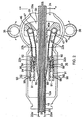
- FIG. 1 is a top view of an embodiment of the sheath introducer of the present invention for use with a device inserted therethrough.
- FIG. 2 is top view of an interior of an embodiment of a control handle with a deflection assembly.
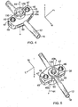
- FIG. 3 is a perspective view of an embodiment of a control handle with a tension knob and a deflection member.
- FIG. 4 is a perspective top view of an embodiment of a rotatable rocker member.
- FIG. 5 is a perspective bottom view of an embodiment of a rocker member.
- FIG. 6 is a perspective view of an embodiment of an interior of a control handle with a rocker member and tensile members.
- FIG. 7 is a side elevational view of an embodiment of a pulley.
- FIGs. 8a-c show an embodiment of a control handle with its deflection assembly in a neutral position, deflection to the right and deflection to the left.
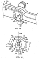
- FIG. 9a is a side cross sectional view of an embodiment of a distal section of a shaft of the introducer 10.
- FIG. 9b is a longitudinal cross sectional view the distal section of FIG. 9a , taken along line b--b.
- FIG. 9c is a longitudinal cross sectional view of the distal section of FIG. 9a , taking along line c--c.
- FIG. 9d is a longitudinal cross sectional view of the shaft of FIG. 8 , taken along line d--d.
- FIG. 9e is a longitudinal cross sectional view of the shaft of FIG. 2 , taken along line e--e.
- FIG. 9f is a side cross sectional view of an alternate embodiment of a distal section of a shaft of the present invention.
- FIG. 10a is a side cross sectional view of an alternate embodiment of a distal tip section of a shaft.
- FIG. 10b is a side cross sectional view of another alternate embodiment of a distal tip section of a shaft.
- FIG. 11 is a longitudinal cross sectional view of an embodiment of a deflection assembly of the control handle.
- FIG. 11a is a detailed view of a portion of the deflection assembly of FIG. 11 , showing a bolt and a retaining nut.
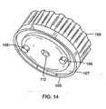
- FIG. 12 is a perspective view of an embodiment of a tension knob.
- FIG. 13 is a perspective view of an embodiment of a locking plate.
- FIG. 14 is a perspective of an embodiment of an assembly including the tension knob and the locking plate.
- FIG. 15 is a perspective view of an embodiment of a control handle.
- FIG. 16 is a partial perspective view of an embodiment of an interior of one housing half of a control handle.
- FIG. 17 is a partial perspective view of an embodiment of an interior of another housing half of a control handle.
- FIG. 18 is a perspective view of an embodiment of a deflection member.
- FIGS. 1 and 2 illustrate an embodiment a steerable bidirectional sheath introducer 10 for use with a catheter, needle or other device 20 (used interchangeably herein) to be extended through the introducer 10 for entry into a patient's body.
- the introducer 10 comprises an elongated shaft 12, and a control handle 16 at the proximal end of the shaft 12.
- the shaft 12 has a deflectable section 15 and a distal tip section 14.
- the shaft 12 has a central lumen 18 that extends its entire length for passage of the catheter or other device 20.
- the shaft 12 extends both distally of the control handle 16 and proximally through the control handle.
- tensile members 22 are provided, with their distal ends anchored at or near the distal tip section 14 and their proximal ends anchored in the control handle 16. Longitudinal movement of the tensile members relative to the shaft 12, which results in deflection of the deflectable section 15, is accomplished by means of the control handle 16 and its deflection assembly 24.
- the control handle 16 comprises a generally elongated handle housing, which can be made of any suitable rigid material, such as plastic configured through a suitable molding process.
- the housing includes two opposing halves 26a and 26b that generally mirror each other and are joined by glue, sonic welding or other suitable means along a longitudinal peripheral seam 28 around the housing.
- the shaft 12 enters the control handle 16 at its distal end ( FIG. 2 ), extends along the longitudinal axis of the control handle 16 and terminates at the proximal end of the control handle in a hemostatis valve 30 ( FIG. 1 ) that has been integrated into the housing of the control handle.
- the hemostatis valve forms a fluid tight seal with the device 20 for various purposes, including keeping the lumen 18 of the shaft 12 at positive pressure to prevent patient's loss of blood through the introducer 10 and minimizing the introduction of air into the patient's body.
- the hemostatis valve 30 connects to a side port 13 having a luer hub 17 through which a vacuum can be created to remove air from the inner lumen 18 or through which fluids can be flushed into the lumen 18 to prevent blood from clotting.
- the control handle 16 houses components of the deflection assembly 24 ( FIG. 3 ) which includes a deflection member or arm 36 that can be directly manipulated by an operator to control deflection of the shaft 12.
- the deflection arm 36 is rotatable about an axis 19 that is generally transverse or perpendicular to the longitudinal axis of the control handle.
- the deflection assembly 24 has a rotatable rocker member 38 that acts on the tensile puller members 22 to deflect the shaft 12.
- the rocker member 38 has a length L dimension, a width W dimension and a thickness T dimension.
- the rocker member 38 is configured with two opposing annular formations 40a and 40b that define a central hole 43 that extends through the thickness of the member 38.
- the central hole 43 defines an axis of rotation 44 that is coaxial with rotational axis 19 of the deflection arm 36.
- the rocker member 38 also has two smaller holes 46 that oppose each other from the central hole 43. In each hole sits a pulley 47, for example, a snap bearing ( FIG. 7 ), that has a rotational axis parallel to the rotational axis 19.
- a tensile member 22 enters the rocker member through slots 48 and a portion is wound around a respective pulley 47.
- the rocker member 38 has a channel 50 extending through its width. Distal and proximal portions of the channel 50 have indents, e.g., triangular or wedge-shaped, 51 ( FIG. 2 ) to allow the rocker member 38 to rotate freely within a predetermined range of angles, e.g., about ⁇ 45 degrees of the longitudinal axis of the control handle 16, without interference with the shaft 12.
- indents e.g., triangular or wedge-shaped, 51 ( FIG. 2 ) to allow the rocker member 38 to rotate freely within a predetermined range of angles, e.g., about ⁇ 45 degrees of the longitudinal axis of the control handle 16, without interference with the shaft 12.
- the rocker member 38 and the pulleys 47 are arranged such that rotation of the rocker member in one direction about the axis 44 draws back one tensile member 22 to deflect the shaft 12 in that direction.
- the pulleys 47 are displaced from a neutral position ( FIG. 8a ) with one pulley 47 drawing a tensile member 22 on one side of the shaft 12 against its anchored proximal end 53 for deflecting the shaft toward that side ( FIGs. 8b and 8c ).
- Each tensile member 22 may comprise multiple segments. As best illustrated in FIG. 2 , each tensile member has a distal puller wire portion 22a and a proximal tensile fiber portion 22b that are joined or connected at a location with in the control handle 16 distal the rocker member 38.
- the puller wire portions 22a and the tensile fiber portions 22b are connected or secured to each other by a connector 54, e.g., a crimped brass ferrule covered by shrink tubing.
- the puller wire portions 22a extend nearly the entirety of shaft portion 12a distal the control handle.
- the tensile fiber portions 22b extend inside the control handle 16 generally outside proximal shaft portion 12b. In this manner, it is the more flexible tensile fiber portions 22b that interact with the pulleys 47 and undergo repeated bending and straightening during deflection operations, as they are less prone to bending stress and fatigue failure.
- Each puller wire portion or puller wire 22a is made of any suitable metal, such as stainless steel or Nitinol.
- each puller wire has a low friction coating, such as a coating of Teflon.RTM. or the like.
- Each puller wire has a diameter preferably ranging from about 0,15 mm to 0,3 mm (0.006 inch to about 0.012 inch).
- both of the puller wires have the same diameter.
- Flat puller wires may be used in place of round puller wires. Their cross sectional dimensions should be such that they provide comparable tensile strengths as round puller wires.
- Each tensile fiber portion or tensile fiber 22b may be of a high modulus fiber material, preferably having an ultimate tensile strength substantially in the range of 412-463 ksi (2480-3200 Mpa) such as High Molecular Density Polyethylene (e.g., Spectra TM or Dyneema TM), a spun para-aramid fiber polymer (e.g., Kevlar TM) or a melt spun liquid crystal polymer fiber rope (e.g., Vectran TM), or a high strength ceramic fiber (e.g., Nextel TM).
- the term fiber is used herein interchangeably with the term fibers in that the tensile fiber may be of a woven or braided construction.
- these materials tend to be flexible, providing suitable durability when used in wrapped engagement with the pulleys and the like for greater throw in deflecting the catheter tip. Further, they are substantially non-stretching, which increases the responsiveness to the manipulation of the control handle, and nonmagnetic so that they generally appear transparent to an MRI. The low density of the material causes it to be generally transparent to an x-ray machine. The materials can also be nonconductive to avoid shorting.
- VectranTM for example, has high strength, high abrasion resistance, is an electrical insulator, nonmagnetic, is polymeric, and has low elongation under sustained loading conditions.
- the shaft 12 comprises an elongated tubular construction having a single, axial or central lumen 18, and two considerably smaller off-axis channels or lumens 42, one on each side of the central lumen 18 along a diameter of the shaft 12.
- Each channel 42 may be lined by a compression coil or stiffener 41 ( FIG. 9b ) from the proximal end of the shaft 12 at the hemostatis valve 30 inside the control handle 16 to a proximal end of the deflectable section 15 ( FIG. 1 ) to resist buckling during deflection of the deflectable section 15.
- an inner layer or lining 60 (e.g., of PTFE or TEFLON.RTM.) which reduces friction and enhances smooth passage of a catheter or device through the shaft.
- the lining 60 is surrounded by a braided mesh 62 of stainless steel or the like that is covered by an outer layer body 64.
- the braided mesh 62 increases the torsional stiffness of the shaft 12 so that when the control handle 16 is rotated the distal end of the shaft 12 will rotate in a corresponding manner.
- the outer layer 64 may be made of a suitable polymer, such as polyurethane or PEBAX.RTM. (polyether block amide).
- the outer layer 64 can better bond the braided mesh 62 to the lining 60.
- the outer diameter of the shaft 12 is preferably no more than about 4.17mm (12.5 french), more preferably about 3.83mm (11.5 french).
- the inner diameter or central lumen 18 of the shaft is preferably no less than about 2.67mm (8 french), more preferably between about 2.75 and 2.83mm (8.25 and 8.5 french).
- the off-axis channels 42 may be formed in the outer layer 64 during extrusion or molding for shafts manufactured with such processes.
- the channels 42 may also be formed by means of a round flat tube (of PTFE or other suitable material) during lamination of the outer layer. It is understood by one of ordinary skill in the art that the material, shape and size of the tube may vary to accommodate various tensile member designs and materials.
- a port or opening 66 is cut or otherwise provided at a location along the proximal shaft portion 12a extending within the control handle 16 to allow the tensile members 22 to enter the off-axis channels 42.
- the distal puller wire portions 22a of the tensile member passes into the openings 66 and extend distally into the channels 42 of the shaft.
- the shaft 12 includes a distal tip section 14 distal of the deflectable section 15.
- the distal tip section comprises a conical tip 70, a fastener, e.g., a ring attachment 72, for the tensile member and a transition portion 74 that bridges the deflectable section 15 and the conical tip 70.
- the conical tip can be made of a soft, radiopaque material.
- the central lumen extends through the distal tip section 14.
- the outer layer 64 of the shaft terminates at the proximal end of the distal section 14, the lining 60 and the braided mesh 62 of the shaft 12 extend into the transition position 74 and are covered by an outer layer 76.
- the outer layer 76 has a different durometer than the outer layer 64 so that the transition portion 74 can be softer and more flexible than the shaft 12.
- the outer layer 76 can be a softer and more flexible cannula material.
- the off-axis channels 42 continue extended through the outer layer 76.
- the outer layer 76 of the transition portion 74 may be comprised of multiple sections 76a - 76d of materials with different durometers to provide a change in flexibility of the deflectable region 15 relative to location from the conical tip 70 ( FIG. 9f )
- the lining 60 extends from the transition segment 74, through the attachment ring 72 and terminates in the conical tip 70.
- the portion of the lumen 18 in the conical tip 70 tapers accordingly with the conical profile of the tip 70, with a diameter D of the lumen 18 at a distal end being sufficient to allow passage of the device 20 while forming a circumferential fluid-tight seal against the device.
- the material of the conical tip 70 is elastic to facilitate the formation of the seal.
- Ports 82 are provided in the transition segment 74 through the lining 60, the braided mesh 62 and the outer layer 76 so that fluid can escape from the central lumen 18 to prevent the formation of a vacuum as the device 20 moves therethrough.
- the attachment ring 72 serves as an anchor for the tensile members extending through the off-axis channels 42.
- the tensile members 22a emerging from each off axis channel 42 extend through a passage 78 formed in the attachment ring 72 that includes radial passages 78a that are aligned with the off-axis channels 42 and a circumferential passage 78b linking the radial passages.
- the tensile members 22a is a continuous structure that extends from one channel 42 into the other channel 42. Bonding between the tensile members 22a and the ring 72 prevents the tensile members 22a from moving or dislocating.
- the ring 72 can be made of a material similar to that of the conical tip 70 and/or the transition segment outer layer 76, with similar melt temperatures.
- the ring 72 may be formed by lamination or molding. Interfacing edges or junctions within the distal section 14, between the conical tip 70, the ring 72 and the transitional portion 74 can be joined by thermal bonding, and/or glue or adhesives.
- the attachment ring 72 anchors the tensile member 22 so that as a proximal end of the tensile member is drawn proximally by a pulley 47 of the rocker member 38 of the deflection assembly 24, the shaft 12 is deflected toward that tensile member ( FIGS. 8b and 8c ).
- the tensile member 22 can pass through holes 84 formed in the transition segment ring 72 and be wrapped around the outer surface for several windings 85 and be affixed to the outer surface by lamination 86 ( FIG. 10a ).
- the distal ends of the tensile member can be anchored to the side wall of the shaft 12 by means of a T-bar anchor 88 ( FIG. 10b ) as known in the art.
- the tensile members need not be connected or joined in the distal section of the shaft 12.
- Other means for anchoring the tensile members 22 (as either a continuous member or separate members) at or near the tip section 14 would be recognized by those skilled in the art and are included within the scope of the invention.
- the bi-directional deflection of the deflectable section 15 can be symmetrical or asymmetrical, planar or nonplanar, depending on various factors, including the location of the distal anchor(s) of the tensile member(s) are anchored and the configuration of the off-axis channels 42.
- the portions of the tensile members within the control handle 16 are the tensile fiber portions 22b, each of which extends proximally from the connector 54 toward the rocker member 38 where each is wound around a pulley 47 and turns about 180 degrees to double back toward the distal end of the control handle.
- Each proximal end of the tensile member 22b is anchored by an anchor assembly 90 that includes a pair or racks 92, a slug 94 and a stop 96.
- the proximal end of the tensile member 22b extends between a respective channel 91 defined by the pair of racks 92, and the proximal end of each tensile fiber is encased within a molded member or slug 92 sized to fit in and to translate in the channel 91.
- Proximal the slug are the stops 96 that are adjustably positioned in a selected location along the racks 92, for example, by means of interlocking teeth 98 formed in the racks and the stops to releasably lock in the selected position against movement.
- the stops 96 are formed so that each respective tensile fiber 22b can slide through them, below or around them but the stops 96 block the slugs 94 from moving proximally past them. Accordingly, the stops 96 limit the proximal movement of the slugs 94 and anchor the proximal ends of the tensile fibers 22b to effectuate deflection when each is drawn proximally by the deflection assembly 24.
- the stops 96 are selectively positioned between the racks 92 to achieve a desirable tension in each tensile member. The interlocking teeth of the racks 92 and stops 96 allow for fine adjustments in setting the tension.
- the deflection assembly 24 also includes a rotation tension knob 100 that allows an operator to set the ease with which the deflection arm 36 can be rotated.
- the construction and assembly of the deflection assembly 24, inclusive of the deflection arm 36 and the tension knob 100, are described as follows.
- the tension knob 100 has a generally circular cross section with a circumferential edge 102 having a friction-inducing surface ( FIG. 12 ).
- a central circular protrusion 105 and two prongs 106 along a diameter project from a surface 104 of the knob 100.
- a locking plate 103 ( FIG. 13 ) is sandwiched between the knob 100 and the housing half 26b.
- the locking plates has a central opening 107 and two holes 108.
- the two prongs 106 of the knob 100 are inserted through the two holes 108 in the plate 103 and extend therethrough to engage semi-circular grooves 101 ( FIG. 15 ) formed in an outer surface of the housing half 26b.
- the grooves 101 limit the degree of rotation of the knob 100 in clockwise and counterclockwise directions.
- the central opening 107 of the plate 103 ( FIG. 13 ) has different cross-sections that include a larger circular cross-section 109 and a smaller circular cross-section 112.
- the larger circular cross-section 109 receives a head 114 of a cap screw-type bolt 115, and the smaller circular cross-section 112 receives a body 116 of the bolt 115.
- the central protrusion 105 of the tension knob 100 forms a press fit with the head 114 of the bolt 115 to create rotational alignment between these two components.
- the prongs 106 lock and rotationally couple the tension knob 100 and the lock plate 103, and the bolt 115 is rotationally coupled to the plate 103. Coupling of the tension knob 100 and the locking plate 103 may also be achieved by means of welding the two components together. In that case, the prongs 106 need not protrude from the tension knob but rather from the locking plate 103.
- the rocker member 38 is situated between the two halves 26a and 26b of the control handle 16, with each of annular formations 40a and 40b extending respectively through an opening 120a and 120b formed in each housing half.
- the opening 120b in the housing half 26b ( FIG. 16 ) has a larger circular cross section 122 to receive the annular formation 40b, and a polygonal cross-section 124 to receive a matching polygonal cross-section distal end 126 of a retaining nut 136 whose head 138 abuts a circumferential edge 132 ( FIG. 11 ) formed in the central hole 43 of the rocker member 38.
- the body 116 of the bolt 115 extending through the plate 103 is received in the retaining nut 136 to join the tension knob 110 to the rocker member 38, with the housing half 26b and a washer 119 (e.g., Belleville type) secured therebetween.
- the polygonal distal end 126 of the retaining nut 136 rotationally couples the nut 136 and the housing half 26b while a circular body portion 131 ( FIG. 16 ) of the nut 136 allows rotational independence between the nut 136 and the rocker member 38.
- rotation of the knob 100 in one direction which turns the bolt 115 to advance into the retaining nut 136 compresses components including the annular formation 40b and the washer 11 against the housing half 26b which tightens the knob 100.
- rotation of the knob 100 in the opposite direction which turns the bolt 115 to withdraw from the nut 136 releases the compression which loosens the knob 100.
- the rocker member 38 In assembling the deflection arm 36 to the control handle 16, the rocker member 38 is positioned so the annular formation 40a extends through the opening 120a ( FIG. 17 ) in the housing half 26a.
- the annular formation 40a has recesses 150 ( FIG. 4 ) that lock with protrusions 152 projecting from a facing surface 154 of the deflection arm 36 ( FIG. 18 ), which rotationally couple the deflection arm 36 and the rocker member 38.
- the protrusions 152 can snap fit into the recesses 150 and/or be secured by adhesives, glue, sonic welding and the like.
- a central circular protrusion 156 fits into the annular formation 40a of the rocker member 38.
- the shaft 12 of the introducer 10 is introduced into a patient's body through an opening in a vein.
- a guidewire is fed, followed by a dilator, as is generally known in the art.
- the dilator is removed, and the device is introduced through the hemostatis valve 30 at the proximal end of the control handle 16 to enter the central lumen 18of the introducer 10 whereby the guidewire is passed through a guidewire lumen in the device.
- the guidewire is removed from the sheath prior to insertion of the device.
- the iuer hub 17 on the side port 13 can be used to draw or inject fluid into the central lumen 18 of the sheath introducer 10 as needed.
- An electrophysiologist uses one hand to manipulate the control handle 16 of the introducer 10 and his other hand to manipulate the control handle of the device 20.
- the electrophysiologist can deflect the deflectable region 15 of the shaft 12 with one hand while deflecting an exposed deflectable region of the device 20 with the other hand.
- the distal section 14 of the deflectable section 15 with its increased flexibility can be used to provide improved positioning capabilities of the device 20.
- the combined stiffness of the device 20 and the shaft 12 provides improved back support for the device 20 and aids in maintaining positioning once the device 20 is in place..
- the conical tip 70 of the shaft 12 maintains a tight seal with the device 20 so that force is minimized during punctures. Fluid can enter or leave the central lumen 18 of the distal section 14 via ports 82 so that there is no vacuum to prevent the device 20 from moving freely through the central lumen 18 of the shaft 12.
- the deflectable section 15 By rotating the deflection arm 36 to one direction, the deflectable section 15 (along with the device 20 therethrough) is deflected in that direction. By rotating the deflection arm 36 to the other direction, the deflectable section 15 (along with the device 20 therethrough) is deflected in the other direction. If the deflection arm 36 rotates too freely or not readily enough, the electrophysiologist can adjust the tension on the deflection arm 36 by rotating the tension knob 100.
Abstract
Description
- The present invention relates to sheath introducers for use with catheters, and in particular, deflectable sheath introducers with control handles.
- Electrode catheters have been in common use in medical practice for many years. They are used to stimulate and map electrical activity in the heart and to ablate sites of aberrant electrical activity. In use, the electrode catheter is inserted into a major vein or artery, e.g., femoral artery, and then guided into the chamber of the heart which is of concern. Within the heart, the ability to control the exact position and orientation of the catheter tip is critical and largely determines how useful the catheter is.
- The Seldinger technique is a medical procedure for insertion of heart catheters including central venous catheters. It is named after Dr. Sven-Ivar Seldinger (1921-1998), a Swedish radiologist. The technique involves puncturing the vein and inserting a guiding sheath, a guidewire and a dilator into the patient, as is generally known in the art. The dilator is removed, and a catheter is introduced through the guiding sheath whereby a guidewire lumen in the catheter allows the catheter to pass over the guidewire. The guidewire is then removed. For devices not having a guidewire lumen, the guidewire is removed prior to insertion of the device to allow passage. Once the distal end of the catheter reaches the desired location, the guiding sheath is withdrawn to expose the distal end of the catheter which may comprise an electrode assembly for mapping and/or ablation and any other structures to stabilize the electrode assembly in the heart or against the heart wall and tissue. Fluoroscopy may be used to confirm the position of the catheter and to maneuver it to the desired location. Injection of radiocontrast may be used to visualize organs. The sheath may be used for both right-sided procedures, and transseptal electrophysiologic procedures that require puncturing of the septum.
- Bidirectional catheters have been designed to be deflectable in one direction by one puller wire and in the opposite direction within the same plane by a second puller wire. In such a construction, the puller wires extend into opposing off-axis lumens within the tip section of the catheter. So that the tip section can bend in both directions in the same plane, the puller wires and their associated lumens are located along a diameter of the tip section. Such catheters typically have a control handle at their distal end which have a thumb knob and/or a rotatable grip that is manipulated by an electrophysiologist to position catheter distal end at the desired location and/or operate electrode assemblies, such as contraction, expansion, deployment, retraction, etc.
- Deflectable sheaths are also known, however, the deflection mechanism rotates around the axis of the control handle which facilitates two-handed manipulation but is not ideal for single-handed deflection. Thus, the operator cannot simultaneously deflect the sheath and the catheter extending through the sheath. Existing sheaths also use a soft distal tip with an embedded marker band which does not allow for optimal visualization of the most distal tip and does not provide extensive tip flexibility. Moreover, existing sheaths utilize a consistent cross-sectional profile along the longitudinal axis of the deflectable section which does not allow for changing of stiffness properties near the distal end.
-
US 6,440,062 discloses a control wire driving mechanism for use in an endoscope includes a toothed wheel actuated to rotate in a control part of the endoscope. -
US2008/0065011 discloses a delivery apparatus for delivering a prosthetic heart valve to a native valve site via the human vasculature. -
US5626553 discloses an endoscope including a handle held by a user during an endoscopic procedure and an insertion tube attached at its proximal section to the handle. A plurality of control cables extending the length of the insertion tube are securely attached to the insertion tube's distal section and are axially movable to articulate the distal section. Control wheels are rotatably attached to the handle and positioned to be manipulated by the user during the endoscopic procedure. The articulation system is connected at one end to the control cables and at the other end to the control wheels. The articulation system transmits movement of the control wheels to the control cables. The articulation system is partially linearly movable between the control wheels and the control cables upon movement of at least one control wheel so as to provide a mechanical advantage in converting force from the control wheel to the control cable. -
US patent publication no. 2008/0103520 discloses a deflectable catheter which includes a control handle having a deflection assembly including at least one pulley. -
US patent publication no. 2002/082 584 discloses a system and method for delivering a drug to a target site within a patient's body. The system and method include a steerable guide catheter and a drug delivery catheter. - See as well
US 2005/0288627 andWO 2007/081706 . - Accordingly, it is desirable to provide a sheath introducer that has bidirectional deflection and a control handle that allows an operator to manipulate with one hand so he can simultaneously operate the control handle of the catheter extending through the sheath introducer. It is also desirable to provide a shaft, and more specifically a deflectable section of the sheath introducer, with sections of different durometer so that flexibility and softness varies near the distal end of the shaft, and in particular, with increased flexibility and softness toward the distal tip of the shaft. It is further desirable that the distal tip be radiopaque for optimal visualization and that the distal tip forms a seal with the catheter or device extending through the shaft so that minimal force is used during punctures and risk of distal tip prolapsing is reduced.
- The present invention is directed to a deflectable sheath introducer as claimed in claim 1 having a shaft through which a catheter, needle or device can extend, and a control handle incorporating a deflection assembly that an operator can manipulate for deflecting a deflectable region near a distal section of the shaft, wherein the deflection assembly has a deflection member, a rotatable rocker member and at least a pulley that is engaged with a portion of a tensile member. Rotation of the deflection member about an axis generally perpendicular to a longitudinal axis of the control handle draws on the tensile member to deflect the shaft.
- In one embodiment, the introducer has a shaft with a central lumen, a control handle with a deflection assembly, and tensile members each with a distal portion extending along opposing sides of within the shaft and a proximal portion extending within the control handle. The deflection assembly has a deflection arm, and a rocker member rotationally coupled to the deflection arm, wherein the rocker member has at least two pulleys, each engaged with a respective proximal tensile member portion. Rotation of the deflection arm in one direction draws one proximal tensile member portion for deflecting the shaft in the one direction, and rotation of the deflection member in an opposite direction draws the other proximal tensile member portion for deflecting the shaft in the opposite direction.
- In more detailed embodiments, the tensile member has a distal puller wire portion and a proximal fiber portion, and the deflection assembly includes a tension knob for adjusting tension of the deflection member. The shaft extends through the rocker member which has cutout so that the rocker member can rotate without interference from the shaft. The shaft may include a softer and more flexible distal section, with a distal tip of a conical cross-section that forms a fluid-tight seal with the device being guided by the introducer. The shaft is formed with opposing off-axis channels for passing the tensile member along the length of the shaft distal of the control handle. With in the control handle, the tensile member is generally outside of the shaft so it can engage with a pulley of the deflection assembly. At the distal section of the shaft, the tensile member may pass radially across a ring attachment for anchoring the tensile member in the distal section.
- These and other features and advantages of the present invention will be better understood by reference to the following detailed description when considered in conjunction with the accompanying drawings wherein:
-
FIG. 1 is a top view of an embodiment of the sheath introducer of the present invention for use with a device inserted therethrough. -
FIG. 2 is top view of an interior of an embodiment of a control handle with a deflection assembly. -
FIG. 3 is a perspective view of an embodiment of a control handle with a tension knob and a deflection member. -
FIG. 4 is a perspective top view of an embodiment of a rotatable rocker member. -
FIG. 5 is a perspective bottom view of an embodiment of a rocker member. -
FIG. 6 is a perspective view of an embodiment of an interior of a control handle with a rocker member and tensile members. -
FIG. 7 is a side elevational view of an embodiment of a pulley. -
FIGs. 8a-c show an embodiment of a control handle with its deflection assembly in a neutral position, deflection to the right and deflection to the left. -
FIG. 9a is a side cross sectional view of an embodiment of a distal section of a shaft of the introducer 10. -
FIG. 9b is a longitudinal cross sectional view the distal section ofFIG. 9a , taken along line b--b. -
FIG. 9c is a longitudinal cross sectional view of the distal section ofFIG. 9a , taking along line c--c. -
FIG. 9d is a longitudinal cross sectional view of the shaft ofFIG. 8 , taken along line d--d. -
FIG. 9e is a longitudinal cross sectional view of the shaft ofFIG. 2 , taken along line e--e. -
FIG. 9f is a side cross sectional view of an alternate embodiment of a distal section of a shaft of the present invention. -
FIG. 10a is a side cross sectional view of an alternate embodiment of a distal tip section of a shaft. -
FIG. 10b is a side cross sectional view of another alternate embodiment of a distal tip section of a shaft. -
FIG. 11 is a longitudinal cross sectional view of an embodiment of a deflection assembly of the control handle. -
FIG. 11a is a detailed view of a portion of the deflection assembly ofFIG. 11 , showing a bolt and a retaining nut. -
FIG. 12 is a perspective view of an embodiment of a tension knob. -
FIG. 13 is a perspective view of an embodiment of a locking plate. -
FIG. 14 is a perspective of an embodiment of an assembly including the tension knob and the locking plate. -
FIG. 15 is a perspective view of an embodiment of a control handle. -
FIG. 16 is a partial perspective view of an embodiment of an interior of one housing half of a control handle. -
FIG. 17 is a partial perspective view of an embodiment of an interior of another housing half of a control handle. -
FIG. 18 is a perspective view of an embodiment of a deflection member. -
FIGS. 1 and2 illustrate an embodiment a steerable bidirectional sheath introducer 10 for use with a catheter, needle or other device 20 (used interchangeably herein) to be extended through the introducer 10 for entry into a patient's body. The introducer 10 comprises anelongated shaft 12, and acontrol handle 16 at the proximal end of theshaft 12. Distally, theshaft 12 has adeflectable section 15 and adistal tip section 14. Theshaft 12 has acentral lumen 18 that extends its entire length for passage of the catheter orother device 20. Theshaft 12 extends both distally of the control handle 16 and proximally through the control handle. - For deflecting the
deflectable section 15 of theshaft 12,tensile members 22 are provided, with their distal ends anchored at or near thedistal tip section 14 and their proximal ends anchored in the control handle 16. Longitudinal movement of the tensile members relative to theshaft 12, which results in deflection of thedeflectable section 15, is accomplished by means of the control handle 16 and itsdeflection assembly 24. - With reference to
FIGs. 1-3 , the control handle 16 comprises a generally elongated handle housing, which can be made of any suitable rigid material, such as plastic configured through a suitable molding process. In the illustrated embodiment, the housing includes two opposinghalves peripheral seam 28 around the housing. Theshaft 12 enters the control handle 16 at its distal end (FIG. 2 ), extends along the longitudinal axis of the control handle 16 and terminates at the proximal end of the control handle in a hemostatis valve 30 (FIG. 1 ) that has been integrated into the housing of the control handle. The hemostatis valve forms a fluid tight seal with thedevice 20 for various purposes, including keeping thelumen 18 of theshaft 12 at positive pressure to prevent patient's loss of blood through the introducer 10 and minimizing the introduction of air into the patient's body. Moreover, thehemostatis valve 30 connects to aside port 13 having aluer hub 17 through which a vacuum can be created to remove air from theinner lumen 18 or through which fluids can be flushed into thelumen 18 to prevent blood from clotting. - The control handle 16 houses components of the deflection assembly 24 (
FIG. 3 ) which includes a deflection member orarm 36 that can be directly manipulated by an operator to control deflection of theshaft 12. Thedeflection arm 36 is rotatable about anaxis 19 that is generally transverse or perpendicular to the longitudinal axis of the control handle. As illustrated inFIGs. 4-6 , thedeflection assembly 24 has arotatable rocker member 38 that acts on thetensile puller members 22 to deflect theshaft 12. Therocker member 38 has a length L dimension, a width W dimension and a thickness T dimension. - Along its thickness dimension, the
rocker member 38 is configured with two opposingannular formations central hole 43 that extends through the thickness of themember 38. Thecentral hole 43 defines an axis ofrotation 44 that is coaxial withrotational axis 19 of thedeflection arm 36. Along its length, therocker member 38 also has twosmaller holes 46 that oppose each other from thecentral hole 43. In each hole sits apulley 47, for example, a snap bearing (FIG. 7 ), that has a rotational axis parallel to therotational axis 19. Atensile member 22 enters the rocker member throughslots 48 and a portion is wound around arespective pulley 47. - To accommodate the
shaft 12 extending across and through the control handle 16, therocker member 38 has achannel 50 extending through its width. Distal and proximal portions of thechannel 50 have indents, e.g., triangular or wedge-shaped, 51 (FIG. 2 ) to allow therocker member 38 to rotate freely within a predetermined range of angles, e.g., about ±45 degrees of the longitudinal axis of the control handle 16, without interference with theshaft 12. - As understood by one of ordinary skill in the art, the
rocker member 38 and thepulleys 47 are arranged such that rotation of the rocker member in one direction about theaxis 44 draws back onetensile member 22 to deflect theshaft 12 in that direction. With reference toFIGs. 8a-8c , as therocker member 38 is rotated by means of the deflection arm (as represented by line 36), thepulleys 47 are displaced from a neutral position (FIG. 8a ) with onepulley 47 drawing atensile member 22 on one side of theshaft 12 against its anchoredproximal end 53 for deflecting the shaft toward that side (FIGs. 8b and 8c ). - Each
tensile member 22 may comprise multiple segments. As best illustrated inFIG. 2 , each tensile member has a distalpuller wire portion 22a and a proximaltensile fiber portion 22b that are joined or connected at a location with in the control handle 16 distal therocker member 38. Thepuller wire portions 22a and thetensile fiber portions 22b are connected or secured to each other by aconnector 54, e.g., a crimped brass ferrule covered by shrink tubing. Thepuller wire portions 22a extend nearly the entirety ofshaft portion 12a distal the control handle. Thetensile fiber portions 22b extend inside the control handle 16 generally outsideproximal shaft portion 12b. In this manner, it is the more flexibletensile fiber portions 22b that interact with thepulleys 47 and undergo repeated bending and straightening during deflection operations, as they are less prone to bending stress and fatigue failure. - Each puller wire portion or
puller wire 22a is made of any suitable metal, such as stainless steel or Nitinol. Preferably each puller wire has a low friction coating, such as a coating of Teflon.RTM. or the like. Each puller wire has a diameter preferably ranging from about 0,15 mm to 0,3 mm (0.006 inch to about 0.012 inch). Preferably both of the puller wires have the same diameter. Flat puller wires may be used in place of round puller wires. Their cross sectional dimensions should be such that they provide comparable tensile strengths as round puller wires. - Each tensile fiber portion or
tensile fiber 22b may be of a high modulus fiber material, preferably having an ultimate tensile strength substantially in the range of 412-463 ksi (2480-3200 Mpa) such as High Molecular Density Polyethylene (e.g., Spectra ™ or Dyneema ™), a spun para-aramid fiber polymer (e.g., Kevlar ™) or a melt spun liquid crystal polymer fiber rope (e.g., Vectran ™), or a high strength ceramic fiber (e.g., Nextel ™). The term fiber is used herein interchangeably with the term fibers in that the tensile fiber may be of a woven or braided construction. In any case, these materials tend to be flexible, providing suitable durability when used in wrapped engagement with the pulleys and the like for greater throw in deflecting the catheter tip. Further, they are substantially non-stretching, which increases the responsiveness to the manipulation of the control handle, and nonmagnetic so that they generally appear transparent to an MRI. The low density of the material causes it to be generally transparent to an x-ray machine. The materials can also be nonconductive to avoid shorting. Vectran™, for example, has high strength, high abrasion resistance, is an electrical insulator, nonmagnetic, is polymeric, and has low elongation under sustained loading conditions. - In the illustrated embodiment of
FIGs. 9a-9e , theshaft 12 comprises an elongated tubular construction having a single, axial orcentral lumen 18, and two considerably smaller off-axis channels orlumens 42, one on each side of thecentral lumen 18 along a diameter of theshaft 12. Eachchannel 42 may be lined by a compression coil or stiffener 41 (FIG. 9b ) from the proximal end of theshaft 12 at thehemostatis valve 30 inside the control handle 16 to a proximal end of the deflectable section 15 (FIG. 1 ) to resist buckling during deflection of thedeflectable section 15. Lining thelumen 18 of theshaft 12 is an inner layer or lining 60 (e.g., of PTFE or TEFLON.RTM.) which reduces friction and enhances smooth passage of a catheter or device through the shaft. The lining 60 is surrounded by abraided mesh 62 of stainless steel or the like that is covered by anouter layer body 64. Thebraided mesh 62 increases the torsional stiffness of theshaft 12 so that when the control handle 16 is rotated the distal end of theshaft 12 will rotate in a corresponding manner. Theouter layer 64 may be made of a suitable polymer, such as polyurethane or PEBAX.RTM. (polyether block amide). If extruded, theouter layer 64 can better bond thebraided mesh 62 to thelining 60. For 2.67mm (8 french) sheath introducer, the outer diameter of theshaft 12 is preferably no more than about 4.17mm (12.5 french), more preferably about 3.83mm (11.5 french). The inner diameter orcentral lumen 18 of the shaft is preferably no less than about 2.67mm (8 french), more preferably between about 2.75 and 2.83mm (8.25 and 8.5 french). The off-axis channels 42 may be formed in theouter layer 64 during extrusion or molding for shafts manufactured with such processes. Thechannels 42 may also be formed by means of a round flat tube (of PTFE or other suitable material) during lamination of the outer layer. It is understood by one of ordinary skill in the art that the material, shape and size of the tube may vary to accommodate various tensile member designs and materials. - With reference to
FIGs. 6 and9d , a port or opening 66 is cut or otherwise provided at a location along theproximal shaft portion 12a extending within the control handle 16 to allow thetensile members 22 to enter the off-axis channels 42. In the illustrated embodiment, the distalpuller wire portions 22a of the tensile member passes into theopenings 66 and extend distally into thechannels 42 of the shaft. - Distally, the
shaft 12 includes adistal tip section 14 distal of thedeflectable section 15. The distal tip section comprises aconical tip 70, a fastener, e.g., aring attachment 72, for the tensile member and atransition portion 74 that bridges thedeflectable section 15 and theconical tip 70. The conical tip can be made of a soft, radiopaque material. The central lumen extends through thedistal tip section 14. Although theouter layer 64 of the shaft terminates at the proximal end of thedistal section 14, the lining 60 and thebraided mesh 62 of theshaft 12 extend into thetransition position 74 and are covered by anouter layer 76. In the disclosed embodiment, theouter layer 76 has a different durometer than theouter layer 64 so that thetransition portion 74 can be softer and more flexible than theshaft 12. For example, theouter layer 76 can be a softer and more flexible cannula material. As illustrated, the off-axis channels 42 continue extended through theouter layer 76. Furthermore, theouter layer 76 of thetransition portion 74 may be comprised ofmultiple sections 76a - 76d of materials with different durometers to provide a change in flexibility of thedeflectable region 15 relative to location from the conical tip 70 (FIG. 9f ) - The lining 60 extends from the
transition segment 74, through theattachment ring 72 and terminates in theconical tip 70. The portion of thelumen 18 in theconical tip 70 tapers accordingly with the conical profile of thetip 70, with a diameter D of thelumen 18 at a distal end being sufficient to allow passage of thedevice 20 while forming a circumferential fluid-tight seal against the device. To that end, the material of theconical tip 70 is elastic to facilitate the formation of the seal.Ports 82 are provided in thetransition segment 74 through the lining 60, thebraided mesh 62 and theouter layer 76 so that fluid can escape from thecentral lumen 18 to prevent the formation of a vacuum as thedevice 20 moves therethrough. - Between the
conical tip 70 and the distal end of thetransition portion 74, theattachment ring 72 serves as an anchor for the tensile members extending through the off-axis channels 42. With reference toFIG. 9c , thetensile members 22a emerging from each offaxis channel 42 extend through apassage 78 formed in theattachment ring 72 that includesradial passages 78a that are aligned with the off-axis channels 42 and acircumferential passage 78b linking the radial passages. In this case, it is understood that thetensile members 22a is a continuous structure that extends from onechannel 42 into theother channel 42. Bonding between thetensile members 22a and thering 72 prevents thetensile members 22a from moving or dislocating. Thering 72 can be made of a material similar to that of theconical tip 70 and/or the transition segmentouter layer 76, with similar melt temperatures. Thering 72 may be formed by lamination or molding. Interfacing edges or junctions within thedistal section 14, between theconical tip 70, thering 72 and thetransitional portion 74 can be joined by thermal bonding, and/or glue or adhesives. - The
attachment ring 72 anchors thetensile member 22 so that as a proximal end of the tensile member is drawn proximally by apulley 47 of therocker member 38 of thedeflection assembly 24, theshaft 12 is deflected toward that tensile member (FIGS. 8b and 8c ). - Alternatively, the
tensile member 22 can pass throughholes 84 formed in thetransition segment ring 72 and be wrapped around the outer surface forseveral windings 85 and be affixed to the outer surface by lamination 86 (FIG. 10a ). As another alternate embodiment, the distal ends of the tensile member can be anchored to the side wall of theshaft 12 by means of a T-bar anchor 88 (FIG. 10b ) as known in the art. Of course, in this case, the tensile members need not be connected or joined in the distal section of theshaft 12. Other means for anchoring the tensile members 22 (as either a continuous member or separate members) at or near thetip section 14 would be recognized by those skilled in the art and are included within the scope of the invention. It is understood that the bi-directional deflection of thedeflectable section 15 can be symmetrical or asymmetrical, planar or nonplanar, depending on various factors, including the location of the distal anchor(s) of the tensile member(s) are anchored and the configuration of the off-axis channels 42. - Referring back to
FIG. 2 , the portions of the tensile members within the control handle 16 are thetensile fiber portions 22b, each of which extends proximally from theconnector 54 toward therocker member 38 where each is wound around apulley 47 and turns about 180 degrees to double back toward the distal end of the control handle. Each proximal end of thetensile member 22b is anchored by ananchor assembly 90 that includes a pair or racks 92, a slug 94 and astop 96. The proximal end of thetensile member 22b extends between arespective channel 91 defined by the pair ofracks 92, and the proximal end of each tensile fiber is encased within a molded member or slug 92 sized to fit in and to translate in thechannel 91. Proximal the slug are thestops 96 that are adjustably positioned in a selected location along theracks 92, for example, by means of interlockingteeth 98 formed in the racks and the stops to releasably lock in the selected position against movement. The stops 96 are formed so that each respectivetensile fiber 22b can slide through them, below or around them but thestops 96 block the slugs 94 from moving proximally past them. Accordingly, thestops 96 limit the proximal movement of the slugs 94 and anchor the proximal ends of thetensile fibers 22b to effectuate deflection when each is drawn proximally by thedeflection assembly 24. During assembly of the control handle 16 before the twohousing halves stops 96 are selectively positioned between theracks 92 to achieve a desirable tension in each tensile member. The interlocking teeth of theracks 92 and stops 96 allow for fine adjustments in setting the tension. - With reference to
FIGs 3 and11 , thedeflection assembly 24 also includes arotation tension knob 100 that allows an operator to set the ease with which thedeflection arm 36 can be rotated. The construction and assembly of thedeflection assembly 24, inclusive of thedeflection arm 36 and thetension knob 100, are described as follows. - With reference to
FIGS. 3 ,11, and 11a , thedeflection arm 36 and thetension knob 100 are mounted opposite of each other with thehousing halves tension knob 100 has a generally circular cross section with acircumferential edge 102 having a friction-inducing surface (FIG. 12 ). A centralcircular protrusion 105 and twoprongs 106 along a diameter project from asurface 104 of theknob 100. A locking plate 103 (FIG. 13 ) is sandwiched between theknob 100 and thehousing half 26b. The locking plates has acentral opening 107 and twoholes 108. The twoprongs 106 of theknob 100 are inserted through the twoholes 108 in theplate 103 and extend therethrough to engage semi-circular grooves 101 (FIG. 15 ) formed in an outer surface of thehousing half 26b. Thegrooves 101 limit the degree of rotation of theknob 100 in clockwise and counterclockwise directions. Thecentral opening 107 of the plate 103 (FIG. 13 ) has different cross-sections that include a largercircular cross-section 109 and a smallercircular cross-section 112. The largercircular cross-section 109 receives ahead 114 of a cap screw-type bolt 115, and the smallercircular cross-section 112 receives abody 116 of thebolt 115. Thecentral protrusion 105 of thetension knob 100 forms a press fit with thehead 114 of thebolt 115 to create rotational alignment between these two components. Theprongs 106 lock and rotationally couple thetension knob 100 and thelock plate 103, and thebolt 115 is rotationally coupled to theplate 103. Coupling of thetension knob 100 and thelocking plate 103 may also be achieved by means of welding the two components together. In that case, theprongs 106 need not protrude from the tension knob but rather from the lockingplate 103. - With reference to
FIG. 11 , therocker member 38 is situated between the twohalves annular formations opening opening 120b in thehousing half 26b (FIG. 16 ) has a largercircular cross section 122 to receive theannular formation 40b, and apolygonal cross-section 124 to receive a matching polygonal cross-sectiondistal end 126 of a retainingnut 136 whosehead 138 abuts a circumferential edge 132 (FIG. 11 ) formed in thecentral hole 43 of therocker member 38. Thebody 116 of thebolt 115 extending through theplate 103 is received in the retainingnut 136 to join the tension knob 110 to therocker member 38, with thehousing half 26b and a washer 119 (e.g., Belleville type) secured therebetween. The polygonaldistal end 126 of the retainingnut 136 rotationally couples thenut 136 and thehousing half 26b while a circular body portion 131 (FIG. 16 ) of thenut 136 allows rotational independence between thenut 136 and therocker member 38. Thus, rotation of theknob 100 in one direction which turns thebolt 115 to advance into the retainingnut 136 compresses components including theannular formation 40b and the washer 11 against thehousing half 26b which tightens theknob 100. Likewise, rotation of theknob 100 in the opposite direction which turns thebolt 115 to withdraw from thenut 136 releases the compression which loosens theknob 100. - In assembling the
deflection arm 36 to the control handle 16, therocker member 38 is positioned so theannular formation 40a extends through theopening 120a (FIG. 17 ) in thehousing half 26a. Theannular formation 40a has recesses 150 (FIG. 4 ) that lock withprotrusions 152 projecting from a facingsurface 154 of the deflection arm 36 (FIG. 18 ), which rotationally couple thedeflection arm 36 and therocker member 38. Theprotrusions 152 can snap fit into therecesses 150 and/or be secured by adhesives, glue, sonic welding and the like. A centralcircular protrusion 156 fits into theannular formation 40a of therocker member 38. - In use, the
shaft 12 of the introducer 10 is introduced into a patient's body through an opening in a vein. Through thelumen 12 of the introducer 10, a guidewire is fed, followed by a dilator, as is generally known in the art. The dilator is removed, and the device is introduced through thehemostatis valve 30 at the proximal end of the control handle 16 to enter the central lumen 18of the introducer 10 whereby the guidewire is passed through a guidewire lumen in the device. For devices not containing a guidewire lumen, the guidewire is removed from the sheath prior to insertion of the device. Theiuer hub 17 on theside port 13 can be used to draw or inject fluid into thecentral lumen 18 of the sheath introducer 10 as needed. An electrophysiologist uses one hand to manipulate the control handle 16 of the introducer 10 and his other hand to manipulate the control handle of thedevice 20. The electrophysiologist can deflect thedeflectable region 15 of theshaft 12 with one hand while deflecting an exposed deflectable region of thedevice 20 with the other hand. Thedistal section 14 of thedeflectable section 15 with its increased flexibility can be used to provide improved positioning capabilities of thedevice 20. Additionally, the combined stiffness of thedevice 20 and theshaft 12 provides improved back support for thedevice 20 and aids in maintaining positioning once thedevice 20 is in place.. Theconical tip 70 of theshaft 12 maintains a tight seal with thedevice 20 so that force is minimized during punctures. Fluid can enter or leave thecentral lumen 18 of thedistal section 14 viaports 82 so that there is no vacuum to prevent thedevice 20 from moving freely through thecentral lumen 18 of theshaft 12. - By rotating the
deflection arm 36 to one direction, the deflectable section 15 (along with thedevice 20 therethrough) is deflected in that direction. By rotating thedeflection arm 36 to the other direction, the deflectable section 15 (along with thedevice 20 therethrough) is deflected in the other direction. If thedeflection arm 36 rotates too freely or not readily enough, the electrophysiologist can adjust the tension on thedeflection arm 36 by rotating thetension knob 100. - Accordingly, the foregoing description should not be read as pertaining only to the precise structures described and illustrated in the accompanying drawings, but rather should be read consistent with and as support to the following claims which are to have their fullest and fair scope.
Claims (20)
- A deflectable introducer (10) for use with a device for passage into a patient's body, the introducer comprising:a shaft (12) with a deflectable section (15), the shaft having a lumen (18) through which the device can extend;an elongated control handle (16) defining a longitudinal axis;a tensile member (22) extending between the deflectable section and the control handle, wherein the control handle has a deflection assembly (24) comprising a deflection member (36) and a rotatable rocker member (38), the deflection member being rotatable about an axis (19) generally perpendicular to the longitudinal axis of the control handle, the rotatable rocker member being rotationally coupled to the deflection member, the rotatable rocker member having a pulley (47) engaged with a proximal portion of the tensile member situated within the control handle;wherein manipulation of the deflection member in one direction draws on the tensile member for deflecting the deflectable section of the shaft in the one direction.
- An introducer of claim 1, wherein the distal portion of the tensile member is a puller wire (22a) and the proximal portion of the tensile member is a tensile fiber (22b).
- An introducer of claim 1, wherein the deflection assembly includes a tension knob (100) for adjusting tension on the deflection member.
- An introducer of claim 1, wherein the shaft includes a softer distal section (14).
- An introducer of claim 1, wherein the shaft includes a distal tip with a conical cross-section (70).
- An introducer of claim 1, wherein the shaft includes at least an off-axis channel (42) through which the distal tensile member extends.
- An introducer of claim 1, wherein the rotatable rocker member includes a second pulley around which another tensile member proximal portion is wrapped, wherein manipulation of the deflection member in an opposition direction draws on the tensile member for deflecting the deflectable section of the shaft in the opposite direction.
- An introducer of claim 1, wherein the shaft includes a ring (72) with a radial passage (78) through which a distal portion of the distal tensile member extends for anchoring the distal portion of the distal tensile member
- An introducer of claim 8, wherein the passage includes two radial passages (78a) connected by a circumferential passage (78b).
- An introducer of claim 1, wherein the rotatable rocker member includes a second pulley with which another tensile member proximal portion is engaged, wherein manipulation of the deflection member is rotation, and wherein rotation of the deflection member in one direction rotates the rotatable rocker member such that the first pulley draws on its respective proximal tensile member portion for deflecting the deflectable section of the shaft in the one direction, and rotation of the deflection member in the other direction rotates the rotatable rocker member such that the second pulley draws on its respective proximal tensile member portion for deflecting the deflectable section of the shaft in another direction.
- An introducer of claim 10, wherein the control handle further comprises a tension knob (100) adapted for operator manipulation in adjusting ease at which the deflection member can be rotated.
- An introducer of claim 10, wherein the shaft extends through the rotatable rocker member.
- An introducer of claim 10, wherein distal ends of the tensile member are joined to each other.
- An introducer of claim 10, wherein each tensile member comprises a connector (54) connecting its distal portion (22a) and proximal portion (22b) within the control handle.
- An introducer of claim 14, wherein the distal portion comprises puller wire and proximal portion comprises fiber.
- An introducer of claim 15, wherein the puller wire extends in off-axis channels in the shaft and the fiber extends outside of the shaft.
- An introducer of claim 12, wherein the rotatable rocker member has a cutout (51) to allow rotation of the rotatable rocker member with the shaft extending therethrough.
- An introducer of claim 1, wherein the shaft includes a distal tip section that is softer than the deflectable section.
- An introducer of claim 1, wherein the shaft has off axis channels (42) formed therein through which the tensile members extend:
- An introducer of claim 19, wherein the shaft has a lining (60) and an outer layer (64) and the off-axis channels are formed in the outer layer.
Applications Claiming Priority (1)
| Application Number | Priority Date | Filing Date | Title |
|---|---|---|---|
| US12/346,834 US10046141B2 (en) | 2008-12-30 | 2008-12-30 | Deflectable sheath introducer |
Publications (3)
| Publication Number | Publication Date |
|---|---|
| EP2204208A2 EP2204208A2 (en) | 2010-07-07 |
| EP2204208A3 EP2204208A3 (en) | 2010-08-18 |
| EP2204208B1 true EP2204208B1 (en) | 2013-12-25 |
Family
ID=42211892
Family Applications (1)
| Application Number | Title | Priority Date | Filing Date |
|---|---|---|---|
| EP09252919.7A Active EP2204208B1 (en) | 2008-12-30 | 2009-12-29 | Deflectable sheath introducer |
Country Status (7)
| Country | Link |
|---|---|
| US (3) | US10046141B2 (en) |
| EP (1) | EP2204208B1 (en) |
| JP (1) | JP5734562B2 (en) |
| CN (1) | CN101822573B (en) |
| AU (1) | AU2009251158B2 (en) |
| CA (1) | CA2688971C (en) |
| IL (1) | IL203033A (en) |
Cited By (2)
| Publication number | Priority date | Publication date | Assignee | Title |
|---|---|---|---|---|
| US11524139B2 (en) | 2019-07-15 | 2022-12-13 | Medtronic, Inc. | Catheter with active return curve |
| US11524143B2 (en) | 2019-07-15 | 2022-12-13 | Medtronic, Inc. | Catheter with distal and proximal fixation members |
Families Citing this family (102)
| Publication number | Priority date | Publication date | Assignee | Title |
|---|---|---|---|---|
| US9675411B2 (en) * | 2008-07-15 | 2017-06-13 | Biosense Webster, Inc. | Catheter with perforated tip |
| US8137308B2 (en) * | 2008-09-16 | 2012-03-20 | Biosense Webster, Inc. | Catheter with adjustable deflection sensitivity |
| US8241351B2 (en) | 2008-12-22 | 2012-08-14 | Valtech Cardio, Ltd. | Adjustable partial annuloplasty ring and mechanism therefor |
| WO2010073246A2 (en) | 2008-12-22 | 2010-07-01 | Valtech Cardio, Ltd. | Adjustable annuloplasty devices and adjustment mechanisms therefor |
| US10517719B2 (en) | 2008-12-22 | 2019-12-31 | Valtech Cardio, Ltd. | Implantation of repair devices in the heart |
| US8545553B2 (en) | 2009-05-04 | 2013-10-01 | Valtech Cardio, Ltd. | Over-wire rotation tool |
| US8715342B2 (en) | 2009-05-07 | 2014-05-06 | Valtech Cardio, Ltd. | Annuloplasty ring with intra-ring anchoring |
| US10046141B2 (en) | 2008-12-30 | 2018-08-14 | Biosense Webster, Inc. | Deflectable sheath introducer |
| US9254123B2 (en) | 2009-04-29 | 2016-02-09 | Hansen Medical, Inc. | Flexible and steerable elongate instruments with shape control and support elements |
| US9968452B2 (en) | 2009-05-04 | 2018-05-15 | Valtech Cardio, Ltd. | Annuloplasty ring delivery cathethers |
| US8747351B2 (en) | 2009-08-28 | 2014-06-10 | Biosense Webster, Inc. | Catheter with multi-functional control handle having linear mechanism |
| US9033916B2 (en) | 2009-08-28 | 2015-05-19 | Biosense Webster, Inc. | Catheter with multi-functional control handle having rotational mechanism |
| US9949791B2 (en) | 2010-04-26 | 2018-04-24 | Biosense Webster, Inc. | Irrigated catheter with internal position sensor |
| US9943362B2 (en) | 2010-04-28 | 2018-04-17 | Biosense Webster, Inc. | Irrigated ablation catheter with improved fluid flow |
| US9510894B2 (en) | 2010-04-28 | 2016-12-06 | Biosense Webster (Israel) Ltd. | Irrigated ablation catheter having irrigation ports with reduced hydraulic resistance |
| US9943363B2 (en) | 2010-04-28 | 2018-04-17 | Biosense Webster, Inc. | Irrigated ablation catheter with improved fluid flow |
| US9060765B2 (en) | 2010-11-08 | 2015-06-23 | Bovie Medical Corporation | Electrosurgical apparatus with retractable blade |
| US9572508B2 (en) * | 2010-11-09 | 2017-02-21 | St. Jude Medical, Atrial Fibrillation Division, Inc. | In-plane dual loop fixed diameter electrophysiology catheters and methods of manufacturing therefor |
| US9877781B2 (en) | 2010-11-19 | 2018-01-30 | St. Jude Medical, Atrial Fibrillation Division, Inc. | Electrode catheter device with indifferent electrode for direct current tissue therapies |
| US8617087B2 (en) | 2010-12-03 | 2013-12-31 | Biosense Webster, Inc. | Control handle with rotational cam mechanism for contraction/deflection of medical device |
| US8792962B2 (en) | 2010-12-30 | 2014-07-29 | Biosense Webster, Inc. | Catheter with single axial sensors |
| US10792152B2 (en) | 2011-06-23 | 2020-10-06 | Valtech Cardio, Ltd. | Closed band for percutaneous annuloplasty |
| US9351751B2 (en) * | 2011-07-08 | 2016-05-31 | Covidien Lp | Swinging bars with axial wheels to drive articulating cables |
| EP3656434B1 (en) | 2011-11-08 | 2021-10-20 | Valtech Cardio, Ltd. | Controlled steering functionality for implant-delivery tool |
| US8460237B2 (en) * | 2011-11-10 | 2013-06-11 | Biosense Webster (Israel), Ltd. | Medical device control handle with multiplying linear motion |
| US9821143B2 (en) | 2011-12-15 | 2017-11-21 | Imricor Medical Systems, Inc. | Steerable sheath including elastomeric member |
| US9757538B2 (en) | 2011-12-15 | 2017-09-12 | Imricor Medical Systems, Inc. | MRI compatible control handle for steerable sheath with audible, tactile and/or visual means |
| WO2013090558A1 (en) | 2011-12-15 | 2013-06-20 | Imricor Medical Systems, Inc. | Mri compatible handle and steerable sheath |
| US8911397B2 (en) | 2011-12-22 | 2014-12-16 | Boston Scientific Scimed Inc. | Steerable sheath handle pulley mechanism |
| JP2013192691A (en) * | 2012-03-19 | 2013-09-30 | Japan Lifeline Co Ltd | Medical tube control handle and medical tube introducing device |
| US9717554B2 (en) | 2012-03-26 | 2017-08-01 | Biosense Webster (Israel) Ltd. | Catheter with composite construction |
| US10639099B2 (en) | 2012-05-25 | 2020-05-05 | Biosense Webster (Israel), Ltd. | Catheter having a distal section with spring sections for biased deflection |
| BR122020010829B1 (en) | 2012-06-19 | 2022-03-29 | Baylis Medical Company Inc | Control system comprising a steerable catheter control cable and steerable catheter control system for bidirectional control of a steerable catheter |
| CN103536352A (en) * | 2012-07-09 | 2014-01-29 | 李莉 | Balloon expanding renal artery sympathetic nerve ablation catheter |
| CN102793965B (en) * | 2012-07-10 | 2013-12-18 | 上海康德莱企业发展集团医疗器械有限公司 | Intestinal canal balloon catheter |
| CN103565518B (en) * | 2012-08-01 | 2015-09-02 | 四川锦江电子科技有限公司 | Double-control bent electrophysiologicalcatheter catheter |
| EP3730084A1 (en) | 2012-10-23 | 2020-10-28 | Valtech Cardio, Ltd. | Controlled steering functionality for implant-delivery tool |
| CN102921089A (en) * | 2012-11-07 | 2013-02-13 | 南通伊诺精密塑胶导管有限公司 | Bending catheter with controllable head and used for interventional therapy |
| DE102012220682A1 (en) * | 2012-11-13 | 2014-05-28 | Olympus Winter & Ibe Gmbh | Bipolar coagulation and cutting electrode |
| US8894610B2 (en) | 2012-11-28 | 2014-11-25 | Hansen Medical, Inc. | Catheter having unirail pullwire architecture |
| US20140148673A1 (en) | 2012-11-28 | 2014-05-29 | Hansen Medical, Inc. | Method of anchoring pullwire directly articulatable region in catheter |
| EP2737922B1 (en) * | 2012-11-28 | 2016-05-04 | Hansen Medical, Inc. | Catheter having unirail pullwire architecture |
| CN104853801B (en) | 2012-12-18 | 2017-07-14 | 住友电木株式会社 | Medicine equipment |
| US9044156B2 (en) | 2012-12-28 | 2015-06-02 | Biosense Webster (Israel) Ltd. | Catheter with improved safety line for distal tip and related method |
| US9144460B2 (en) | 2012-12-31 | 2015-09-29 | Biosense Webster (Israel) Ltd. | Catheter with direct cooling on nonablating element |
| US9174023B2 (en) | 2013-01-07 | 2015-11-03 | Biosense Webster (Israel) Ltd. | Unidirectional catheter control handle with tensioning control |
| US9375550B2 (en) | 2013-03-15 | 2016-06-28 | St. Jude Medical, Atrial Fibrillation Division, Inc. | Catheter actuators providing mechanical advantage |
| JP5963702B2 (en) * | 2013-03-29 | 2016-08-03 | 日本ライフライン株式会社 | Medical equipment |
| WO2015011817A1 (en) * | 2013-07-25 | 2015-01-29 | 住友ベークライト株式会社 | Medical device |
| US10828089B2 (en) | 2013-08-02 | 2020-11-10 | Biosense Webster (Israel) Ltd. | Catheter with improved irrigated tip electrode having two-piece construction, and method of manufacturing therefor |
| WO2015092768A1 (en) | 2013-12-20 | 2015-06-25 | Baylis Medical Company Inc. | Steerable medical device handle |
| US10194978B2 (en) * | 2014-06-13 | 2019-02-05 | Medtronic Cryocath Lp | Supporting catheter for use for phrenic nerve pacing |
| US11272973B2 (en) | 2015-01-28 | 2022-03-15 | Apyx Medical Corporation | Cold plasma electrosurgical apparatus with bent tip applicator |
| US10869592B2 (en) | 2015-02-23 | 2020-12-22 | Uroviu Corp. | Handheld surgical endoscope |
| US11033715B2 (en) * | 2015-05-18 | 2021-06-15 | Biosense Webster (Israel) Ltd. | Catheter with adjustable deflection |
| CN104841035B (en) * | 2015-06-04 | 2017-12-26 | 桐庐优视医疗器械有限公司 | Plug-type bendable inhaler |
| CN104958824B (en) * | 2015-07-30 | 2018-12-21 | 湖南埃普特医疗器械有限公司 | A kind of guiding catheter |
| US10492857B2 (en) | 2015-08-06 | 2019-12-03 | Boston Scientific Scimed Inc | Deployment control apparatus for a catheter with a deployable array |
| US9931487B2 (en) | 2015-08-06 | 2018-04-03 | Boston Scientific Scimed, Inc. | Bidirectional steering control apparatus for a catheter |
| US10639455B2 (en) | 2015-10-28 | 2020-05-05 | Becton, Dickinson And Company | Closed IV access device with paddle grip needle hub and flash chamber |
| US10525237B2 (en) | 2015-10-28 | 2020-01-07 | Becton, Dickinson And Company | Ergonomic IV systems and methods |
| DE102015225400A1 (en) * | 2015-12-16 | 2017-06-22 | Vimecon Gmbh | Swiveling ablation catheter |
| US10849521B2 (en) | 2015-12-23 | 2020-12-01 | Biosense Webster (Israel) Ltd. | Multi-layered catheter shaft construction with embedded single axial sensors, and related methods |
| US10463439B2 (en) | 2016-08-26 | 2019-11-05 | Auris Health, Inc. | Steerable catheter with shaft load distributions |
| US11684248B2 (en) | 2017-09-25 | 2023-06-27 | Micronvision Corp. | Endoscopy/stereo colposcopy medical instrument |
| US11832797B2 (en) | 2016-09-25 | 2023-12-05 | Micronvision Corp. | Endoscopic fluorescence imaging |
| US10238852B2 (en) * | 2016-10-05 | 2019-03-26 | Becton, Dickinson And Company | Septum housing |
| CN110300557B (en) * | 2016-12-09 | 2022-06-28 | 波士顿科学国际有限公司 | Introducer with expandable properties |
| US11357953B2 (en) | 2016-12-22 | 2022-06-14 | Baylis Medical Company Inc. | Feedback mechanisms for a steerable medical device |
| CN108261256A (en) * | 2016-12-31 | 2018-07-10 | 先健科技(深圳)有限公司 | Conveying device and transport system |
| JP7112100B2 (en) | 2017-01-30 | 2022-08-03 | アピックス メディカル コーポレーション | Electrosurgical device with flexible shaft |
| US10786651B2 (en) * | 2017-03-07 | 2020-09-29 | Talon Medical, LLC | Steerable guide catheter |
| US11877788B2 (en) | 2017-05-30 | 2024-01-23 | Apyx Medical Corporation | Electrosurgical apparatus with robotic tip |
| US11103304B2 (en) | 2017-06-13 | 2021-08-31 | Biosense Webster (Israel) Ltd. | Catheter with composite insert support member |
| US11284939B2 (en) | 2017-07-06 | 2022-03-29 | Biosense Webster (Israel) Ltd. | Irrigated catheter with improved ablation tip electrode fluid distribution |
| US11771304B1 (en) | 2020-11-12 | 2023-10-03 | Micronvision Corp. | Minimally invasive endoscope |
| EP3691732A4 (en) | 2017-10-06 | 2021-09-01 | Baylis Medical Company Inc. | Reinforced sheath for a steerable sheath assembly |
| JP7188847B2 (en) * | 2017-10-24 | 2022-12-13 | エコール ポリテクニーク フェデラル ド ローザンヌ (ウペエフエル) | Maneuverable devices and systems |
| US11517715B2 (en) * | 2018-01-02 | 2022-12-06 | Biosense Webster (Israel) Ltd. | Deflectable medical probe |
| EP3868433A1 (en) * | 2018-02-12 | 2021-08-25 | 510 Kardiac Devices, Inc. | A handle for an introducer sheath |
| US10966783B2 (en) | 2018-03-19 | 2021-04-06 | Biosense Webster (Israel) Ltd. | Catheter with multifunctional microinjection—molded housing |
| CN112423824B (en) * | 2018-05-17 | 2023-02-21 | 92号医疗公司 | Aspiration catheter system and method of use |
| US11013396B2 (en) * | 2018-09-10 | 2021-05-25 | Uroviu Corporation | Portable endoscope with disposable steerable cannula |
| CN109394339B (en) * | 2018-10-19 | 2023-08-22 | 邦士医疗科技股份有限公司 | Plasma operation electrode with bendable and direction-changeable head |
| US10646104B1 (en) * | 2018-10-29 | 2020-05-12 | G.I. View Ltd. | Disposable endoscope |
| WO2020088138A1 (en) * | 2018-10-31 | 2020-05-07 | 杭州唯强医疗科技有限公司 | Bend adjusting handle and bend-adjustable catheter |
| CN109350321A (en) * | 2018-12-06 | 2019-02-19 | 南京法迈特科技发展有限公司 | Stenter to implant device under visibility status |
| US20220218929A1 (en) * | 2019-06-02 | 2022-07-14 | Wolf Technical Services, Inc. | Tube introducer intubation device |
| EP4003138A4 (en) | 2019-07-25 | 2023-08-30 | Uroviu Corp. | Disposable endoscopy cannula with integrated grasper |
| US20220241551A1 (en) * | 2019-09-16 | 2022-08-04 | Middleton Medical Innovations Pty Ltd | Urinary catheter and method of catheterising a bladder using an actively deflectable urethral catheter and a deflection mechanism |
| US11471650B2 (en) | 2019-09-20 | 2022-10-18 | Biosense Webster (Israel) Ltd. | Mechanism for manipulating a puller wire |
| WO2021230734A1 (en) * | 2020-05-15 | 2021-11-18 | 주식회사 다인그룹 | Endoscope |
| AU2021291294A1 (en) | 2020-06-19 | 2023-02-02 | Remedy Robotics, Inc. | Systems and methods for guidance of intraluminal devices within the vasculature |
| CN112618099B (en) * | 2020-12-31 | 2023-10-20 | 先健科技(深圳)有限公司 | In-situ window opening device |
| US11707332B2 (en) | 2021-07-01 | 2023-07-25 | Remedy Robotics, Inc. | Image space control for endovascular tools |
| AU2022305235A1 (en) | 2021-07-01 | 2024-01-18 | Remedy Robotics, Inc. | Vision-based position and orientation determination for endovascular tools |
| US20230089485A1 (en) | 2021-09-23 | 2023-03-23 | Biosense Webster (Israel) Ltd. | Floating hemostasis valve |
| US20230137558A1 (en) | 2021-10-28 | 2023-05-04 | Biosense Webster (Israel) Ltd. | Compound valve system for intracardiac tools |
| CN116407348A (en) * | 2021-12-31 | 2023-07-11 | 杭州德晋医疗科技有限公司 | Adjustable curved sheath tube and medical instrument conveying system |
| CN114305807B (en) * | 2022-03-10 | 2022-11-18 | 上海申淇医疗科技有限公司 | Tricuspid valve repair device |
| WO2024036336A2 (en) * | 2022-08-12 | 2024-02-15 | Imricor Medical Systems Inc. | Systems and methods for providing a steerable sheath with improved torque transfer during deflection |
| CN116172689B (en) * | 2022-12-22 | 2023-11-07 | 上海玮启医疗器械有限公司 | Medical catheter capable of being bent in two directions |
Citations (1)
| Publication number | Priority date | Publication date | Assignee | Title |
|---|---|---|---|---|
| US20020082584A1 (en) * | 2000-12-22 | 2002-06-27 | Rosenman Daniel C. | Drug delivery catheters that attach to tissue and methods for their use |
Family Cites Families (62)
| Publication number | Priority date | Publication date | Assignee | Title |
|---|---|---|---|---|
| JPS5931202Y2 (en) | 1976-12-16 | 1984-09-05 | 株式会社メドス研究所 | Bending operation device for endoscopes |
| US4444195A (en) * | 1981-11-02 | 1984-04-24 | Cordis Corporation | Cardiac lead having multiple ring electrodes |
| US4592372A (en) * | 1984-05-22 | 1986-06-03 | Cordis Corporation | Pacing/sensing electrode sleeve and method of forming same |
| US4777955A (en) * | 1987-11-02 | 1988-10-18 | Cordis Corporation | Left ventricle mapping probe |
| JPH0346724Y2 (en) | 1988-02-22 | 1991-10-03 | ||
| US4947827A (en) | 1988-12-30 | 1990-08-14 | Opielab, Inc. | Flexible endoscope |
| US4930521A (en) * | 1989-03-17 | 1990-06-05 | Metzger William T | Variable stiffness esophageal catheter |
| US4996974A (en) * | 1989-04-17 | 1991-03-05 | Welch Allyn, Inc. | Adjustable steering control for flexible probe |
| JPH0337033A (en) * | 1989-07-05 | 1991-02-18 | Machida Seisakusho:Kk | Bending action device for endoscope |
| US5273535A (en) * | 1991-11-08 | 1993-12-28 | Ep Technologies, Inc. | Catheter with electrode tip having asymmetric left and right curve configurations |
| US6033378A (en) * | 1990-02-02 | 2000-03-07 | Ep Technologies, Inc. | Catheter steering mechanism |
| US5891088A (en) | 1990-02-02 | 1999-04-06 | Ep Technologies, Inc. | Catheter steering assembly providing asymmetric left and right curve configurations |
| US5358478A (en) | 1990-02-02 | 1994-10-25 | Ep Technologies, Inc. | Catheter steering assembly providing asymmetric left and right curve configurations |
| US6413234B1 (en) | 1990-02-02 | 2002-07-02 | Ep Technologies, Inc. | Assemblies for creating compound curves in distal catheter regions |
| US5195968A (en) * | 1990-02-02 | 1993-03-23 | Ingemar Lundquist | Catheter steering mechanism |
| ATE123957T1 (en) * | 1990-12-07 | 1995-07-15 | Ruesch Willy Ag | MEDICAL INSTRUMENT WITH DIRECTORABLE TIP. |
| US5328467A (en) | 1991-11-08 | 1994-07-12 | Ep Technologies, Inc. | Catheter having a torque transmitting sleeve |
| US5363861A (en) | 1991-11-08 | 1994-11-15 | Ep Technologies, Inc. | Electrode tip assembly with variable resistance to bending |
| US5325845A (en) * | 1992-06-08 | 1994-07-05 | Adair Edwin Lloyd | Steerable sheath for use with selected removable optical catheter |
| US5462527A (en) * | 1993-06-29 | 1995-10-31 | C.R. Bard, Inc. | Actuator for use with steerable catheter |
| US5545200A (en) * | 1993-07-20 | 1996-08-13 | Medtronic Cardiorhythm | Steerable electrophysiology catheter |
| US6032061A (en) * | 1997-02-20 | 2000-02-29 | Boston Scientifc Corporation | Catheter carrying an electrode and methods of assembly |
| US5885288A (en) * | 1994-05-24 | 1999-03-23 | Endius Incorporated | Surgical instrument |
| US5667476A (en) * | 1995-06-05 | 1997-09-16 | Vision-Sciences, Inc. | Endoscope articulation system to reduce effort during articulation of an endoscope |
| US5676653A (en) * | 1995-06-27 | 1997-10-14 | Arrow International Investment Corp. | Kink-resistant steerable catheter assembly |
| US6144870A (en) * | 1996-10-21 | 2000-11-07 | Procath Corporation | Catheter with improved electrodes and method of fabrication |
| US6213974B1 (en) * | 1996-12-30 | 2001-04-10 | Visionary Biomedical, Inc. | Steerable catheter having segmented tip and one-piece inlet housing, and method of fabricating same |
| US6030360A (en) | 1996-12-30 | 2000-02-29 | Biggs; Robert C. | Steerable catheter |
| US5904667A (en) | 1997-03-17 | 1999-05-18 | C.R. Bard, Inc. | Rotatable control mechanism for steerable catheter |
| US6171277B1 (en) | 1997-12-01 | 2001-01-09 | Cordis Webster, Inc. | Bi-directional control handle for steerable catheter |
| US6224609B1 (en) * | 1998-03-16 | 2001-05-01 | Teramed Inc. | Bifurcated prosthetic graft |
| US6198974B1 (en) | 1998-08-14 | 2001-03-06 | Cordis Webster, Inc. | Bi-directional steerable catheter |
| US6544215B1 (en) | 1998-10-02 | 2003-04-08 | Scimed Life Systems, Inc. | Steerable device for introducing diagnostic and therapeutic apparatus into the body |
| US6210407B1 (en) | 1998-12-03 | 2001-04-03 | Cordis Webster, Inc. | Bi-directional electrode catheter |
| US6374476B1 (en) * | 1999-03-03 | 2002-04-23 | Codris Webster, Inc. | Method for making a catheter tip section |
| US7226467B2 (en) * | 1999-04-09 | 2007-06-05 | Evalve, Inc. | Fixation device delivery catheter, systems and methods of use |
| US6829497B2 (en) * | 1999-09-21 | 2004-12-07 | Jamil Mogul | Steerable diagnostic catheters |
| US6440062B1 (en) | 1999-11-10 | 2002-08-27 | Asahi Kogaku Kogyo Kabushiki Kaisha | Control wire driving mechanism for use in endoscope |
| US6648874B2 (en) * | 2000-02-28 | 2003-11-18 | Scimed Life Systems, Inc. | Guide catheter with lubricious inner liner |
| US20010025134A1 (en) * | 2000-03-15 | 2001-09-27 | Edwin Bon | Catheter tip with bridged steering wire sleeve element |
| US7056294B2 (en) * | 2000-04-13 | 2006-06-06 | Ev3 Sunnyvale, Inc | Method and apparatus for accessing the left atrial appendage |
| US6530897B2 (en) | 2000-04-28 | 2003-03-11 | Mahase Nardeo | Steerable medical catheter with bendable encapsulated metal spring tip fused to polymeric shaft |
| US6579278B1 (en) | 2000-05-05 | 2003-06-17 | Scimed Life Systems, Inc. | Bi-directional steerable catheter with asymmetric fulcrum |
| JP2004532074A (en) * | 2001-04-27 | 2004-10-21 | シー・アール・バード・インコーポレーテッド | Design of handle for medical catheter |
| US6585718B2 (en) * | 2001-05-02 | 2003-07-01 | Cardiac Pacemakers, Inc. | Steerable catheter with shaft support system for resisting axial compressive loads |
| US6652506B2 (en) | 2001-05-04 | 2003-11-25 | Cardiac Pacemakers, Inc. | Self-locking handle for steering a single or multiple-profile catheter |
| US6648875B2 (en) | 2001-05-04 | 2003-11-18 | Cardiac Pacemakers, Inc. | Means for maintaining tension on a steering tendon in a steerable catheter |
| US7025759B2 (en) | 2002-02-04 | 2006-04-11 | Ebi, L.P. | Steerable catheter |
| US20050021003A1 (en) * | 2003-04-14 | 2005-01-27 | Richard Caso | Apparatus for directional guidance of a vascular device and method of use |
| US7101362B2 (en) * | 2003-07-02 | 2006-09-05 | St. Jude Medical, Atrial Fibrillation Division, Inc. | Steerable and shapable catheter employing fluid force |
| US8136241B2 (en) * | 2003-11-12 | 2012-03-20 | Biosense Webster, Inc. | Method for making a low ohmic pressure-contact electrical connection between the ring electrode under surface and the lead wire |
| US7591799B2 (en) * | 2004-06-14 | 2009-09-22 | Biosense Webster, Inc. | Steering mechanism for bi-directional catheter |
| US7377906B2 (en) * | 2004-06-15 | 2008-05-27 | Biosense Webster, Inc. | Steering mechanism for bi-directional catheter |
| JP4881552B2 (en) | 2004-09-09 | 2012-02-22 | ルネサスエレクトロニクス株式会社 | Semiconductor device |
| CN101247847B (en) | 2005-07-11 | 2013-01-09 | 导管机器人技术公司 | Remotely controlled catheter insertion system |
| CA2627581C (en) * | 2005-10-31 | 2011-03-15 | Wilson-Cook Medical Inc. | Steerable catheter devices and methods of articulating catheter devices |
| US20070232858A1 (en) | 2006-03-31 | 2007-10-04 | Boston Scientific Scimed, Inc. | Steering system tension control devices |
| DE602007007050D1 (en) * | 2006-09-08 | 2010-07-22 | Edwards Lifesciences Corp | |
| US7931616B2 (en) * | 2006-10-31 | 2011-04-26 | Biosense Webster, Inc. | Insert molded catheter puller member connectors and method of making |
| WO2008150767A2 (en) | 2007-05-31 | 2008-12-11 | Boston Scientific Scimed, Inc. | Active controlled bending in medical devices |
| US8048024B2 (en) | 2008-03-17 | 2011-11-01 | Boston Scientific Scimed, Inc. | Steering mechanism |
| US10046141B2 (en) | 2008-12-30 | 2018-08-14 | Biosense Webster, Inc. | Deflectable sheath introducer |
-
2008
- 2008-12-30 US US12/346,834 patent/US10046141B2/en active Active
-
2009
- 2009-12-22 CA CA2688971A patent/CA2688971C/en not_active Expired - Fee Related
- 2009-12-23 AU AU2009251158A patent/AU2009251158B2/en not_active Ceased
- 2009-12-28 JP JP2009296999A patent/JP5734562B2/en active Active
- 2009-12-29 IL IL203033A patent/IL203033A/en active IP Right Grant
- 2009-12-29 EP EP09252919.7A patent/EP2204208B1/en active Active
- 2009-12-30 CN CN200910263745.6A patent/CN101822573B/en active Active
-
2018
- 2018-08-13 US US16/102,008 patent/US10980976B2/en active Active
-
2021
- 2021-04-19 US US17/234,561 patent/US20210236775A1/en active Pending
Patent Citations (1)
| Publication number | Priority date | Publication date | Assignee | Title |
|---|---|---|---|---|
| US20020082584A1 (en) * | 2000-12-22 | 2002-06-27 | Rosenman Daniel C. | Drug delivery catheters that attach to tissue and methods for their use |
Cited By (2)
| Publication number | Priority date | Publication date | Assignee | Title |
|---|---|---|---|---|
| US11524139B2 (en) | 2019-07-15 | 2022-12-13 | Medtronic, Inc. | Catheter with active return curve |
| US11524143B2 (en) | 2019-07-15 | 2022-12-13 | Medtronic, Inc. | Catheter with distal and proximal fixation members |
Also Published As
| Publication number | Publication date |
|---|---|
| CN101822573B (en) | 2014-06-04 |
| AU2009251158A1 (en) | 2010-07-15 |
| CA2688971A1 (en) | 2010-06-30 |
| EP2204208A2 (en) | 2010-07-07 |
| EP2204208A3 (en) | 2010-08-18 |
| JP5734562B2 (en) | 2015-06-17 |
| IL203033A (en) | 2015-01-29 |
| US20210236775A1 (en) | 2021-08-05 |
| CN101822573A (en) | 2010-09-08 |
| JP2010155081A (en) | 2010-07-15 |
| US20100168827A1 (en) | 2010-07-01 |
| US10980976B2 (en) | 2021-04-20 |
| CA2688971C (en) | 2019-12-03 |
| AU2009251158B2 (en) | 2015-06-18 |
| US20180344979A1 (en) | 2018-12-06 |
| US10046141B2 (en) | 2018-08-14 |
Similar Documents
| Publication | Publication Date | Title |
|---|---|---|
| US20210236775A1 (en) | Deflectable sheath introducer | |
| EP0904796B1 (en) | Omni-directional steerable catheter | |
| US7608056B2 (en) | Steerable catheter devices and methods of articulating catheter devices | |
| JP4907351B2 (en) | Bendable catheter assembly and method of manufacturing the same | |
| AU2010210001B2 (en) | Catheter with multi-functional control handle having rotational mechanism | |
| US8663196B2 (en) | Endovascular sheath with gradable stiffness device and method | |
| US6511471B2 (en) | Drug delivery catheters that attach to tissue and methods for their use | |
| JP2009537280A (en) | Mobile medical device | |
| CA2316839A1 (en) | Deflectable guiding catheter | |
| US11344702B2 (en) | Steerable sheath | |
| CN108158571B (en) | Steerable introducer sheath with ring electrode and related method of construction | |
| EP3881755A1 (en) | Steerable sheath with variable curve span | |
| CN219050013U (en) | Sheath tube | |
| JP2023091652A (en) | Catheter handle and catheter equipped with the same | |
| CN115803076A (en) | Electrically actuated articulating catheter system |
Legal Events
| Date | Code | Title | Description |
|---|---|---|---|
| PUAI | Public reference made under article 153(3) epc to a published international application that has entered the european phase |
Free format text: ORIGINAL CODE: 0009012 |
|
| AK | Designated contracting states |
Kind code of ref document: A2 Designated state(s): AT BE BG CH CY CZ DE DK EE ES FI FR GB GR HR HU IE IS IT LI LT LU LV MC MK MT NL NO PL PT RO SE SI SK SM TR |
|
| AX | Request for extension of the european patent |
Extension state: AL BA RS |
|
| PUAL | Search report despatched |
Free format text: ORIGINAL CODE: 0009013 |
|
| AK | Designated contracting states |
Kind code of ref document: A3 Designated state(s): AT BE BG CH CY CZ DE DK EE ES FI FR GB GR HR HU IE IS IT LI LT LU LV MC MK MT NL NO PL PT RO SE SI SK SM TR |
|
| AX | Request for extension of the european patent |
Extension state: AL BA RS |
|
| 17P | Request for examination filed |
Effective date: 20110217 |
|
| 17Q | First examination report despatched |
Effective date: 20110518 |
|
| GRAP | Despatch of communication of intention to grant a patent |
Free format text: ORIGINAL CODE: EPIDOSNIGR1 |
|
| GRAP | Despatch of communication of intention to grant a patent |
Free format text: ORIGINAL CODE: EPIDOSNIGR1 |
|
| INTG | Intention to grant announced |
Effective date: 20130813 |
|
| GRAS | Grant fee paid |
Free format text: ORIGINAL CODE: EPIDOSNIGR3 |
|
| GRAA | (expected) grant |
Free format text: ORIGINAL CODE: 0009210 |
|
| AK | Designated contracting states |
Kind code of ref document: B1 Designated state(s): AT BE BG CH CY CZ DE DK EE ES FI FR GB GR HR HU IE IS IT LI LT LU LV MC MK MT NL NO PL PT RO SE SI SK SM TR |
|
| REG | Reference to a national code |
Ref country code: GB Ref legal event code: FG4D |
|
| REG | Reference to a national code |
Ref country code: CH Ref legal event code: EP |
|
| REG | Reference to a national code |
Ref country code: AT Ref legal event code: REF Ref document number: 646236 Country of ref document: AT Kind code of ref document: T Effective date: 20140115 |
|
| REG | Reference to a national code |
Ref country code: IE Ref legal event code: FG4D |
|
| REG | Reference to a national code |
Ref country code: DE Ref legal event code: R096 Ref document number: 602009020948 Country of ref document: DE Effective date: 20140213 |
|
| REG | Reference to a national code |
Ref country code: NL Ref legal event code: T3 |
|
| PG25 | Lapsed in a contracting state [announced via postgrant information from national office to epo] |
Ref country code: NO Free format text: LAPSE BECAUSE OF FAILURE TO SUBMIT A TRANSLATION OF THE DESCRIPTION OR TO PAY THE FEE WITHIN THE PRESCRIBED TIME-LIMIT Effective date: 20140325 Ref country code: HR Free format text: LAPSE BECAUSE OF FAILURE TO SUBMIT A TRANSLATION OF THE DESCRIPTION OR TO PAY THE FEE WITHIN THE PRESCRIBED TIME-LIMIT Effective date: 20131225 Ref country code: SE Free format text: LAPSE BECAUSE OF FAILURE TO SUBMIT A TRANSLATION OF THE DESCRIPTION OR TO PAY THE FEE WITHIN THE PRESCRIBED TIME-LIMIT Effective date: 20131225 Ref country code: LT Free format text: LAPSE BECAUSE OF FAILURE TO SUBMIT A TRANSLATION OF THE DESCRIPTION OR TO PAY THE FEE WITHIN THE PRESCRIBED TIME-LIMIT Effective date: 20131225 Ref country code: FI Free format text: LAPSE BECAUSE OF FAILURE TO SUBMIT A TRANSLATION OF THE DESCRIPTION OR TO PAY THE FEE WITHIN THE PRESCRIBED TIME-LIMIT Effective date: 20131225 |
|
| REG | Reference to a national code |
Ref country code: AT Ref legal event code: MK05 Ref document number: 646236 Country of ref document: AT Kind code of ref document: T Effective date: 20131225 |
|
| REG | Reference to a national code |
Ref country code: LT Ref legal event code: MG4D |
|
| PG25 | Lapsed in a contracting state [announced via postgrant information from national office to epo] |
Ref country code: LV Free format text: LAPSE BECAUSE OF FAILURE TO SUBMIT A TRANSLATION OF THE DESCRIPTION OR TO PAY THE FEE WITHIN THE PRESCRIBED TIME-LIMIT Effective date: 20131225 |
|
| PG25 | Lapsed in a contracting state [announced via postgrant information from national office to epo] |
Ref country code: EE Free format text: LAPSE BECAUSE OF FAILURE TO SUBMIT A TRANSLATION OF THE DESCRIPTION OR TO PAY THE FEE WITHIN THE PRESCRIBED TIME-LIMIT Effective date: 20131225 Ref country code: IS Free format text: LAPSE BECAUSE OF FAILURE TO SUBMIT A TRANSLATION OF THE DESCRIPTION OR TO PAY THE FEE WITHIN THE PRESCRIBED TIME-LIMIT Effective date: 20140425 |
|
| REG | Reference to a national code |
Ref country code: CH Ref legal event code: PL |
|
| PG25 | Lapsed in a contracting state [announced via postgrant information from national office to epo] |
Ref country code: RO Free format text: LAPSE BECAUSE OF FAILURE TO SUBMIT A TRANSLATION OF THE DESCRIPTION OR TO PAY THE FEE WITHIN THE PRESCRIBED TIME-LIMIT Effective date: 20131225 Ref country code: SK Free format text: LAPSE BECAUSE OF FAILURE TO SUBMIT A TRANSLATION OF THE DESCRIPTION OR TO PAY THE FEE WITHIN THE PRESCRIBED TIME-LIMIT Effective date: 20131225 Ref country code: ES Free format text: LAPSE BECAUSE OF FAILURE TO SUBMIT A TRANSLATION OF THE DESCRIPTION OR TO PAY THE FEE WITHIN THE PRESCRIBED TIME-LIMIT Effective date: 20131225 Ref country code: PL Free format text: LAPSE BECAUSE OF FAILURE TO SUBMIT A TRANSLATION OF THE DESCRIPTION OR TO PAY THE FEE WITHIN THE PRESCRIBED TIME-LIMIT Effective date: 20131225 Ref country code: CY Free format text: LAPSE BECAUSE OF FAILURE TO SUBMIT A TRANSLATION OF THE DESCRIPTION OR TO PAY THE FEE WITHIN THE PRESCRIBED TIME-LIMIT Effective date: 20131225 Ref country code: CZ Free format text: LAPSE BECAUSE OF FAILURE TO SUBMIT A TRANSLATION OF THE DESCRIPTION OR TO PAY THE FEE WITHIN THE PRESCRIBED TIME-LIMIT Effective date: 20131225 Ref country code: AT Free format text: LAPSE BECAUSE OF FAILURE TO SUBMIT A TRANSLATION OF THE DESCRIPTION OR TO PAY THE FEE WITHIN THE PRESCRIBED TIME-LIMIT Effective date: 20131225 Ref country code: PT Free format text: LAPSE BECAUSE OF FAILURE TO SUBMIT A TRANSLATION OF THE DESCRIPTION OR TO PAY THE FEE WITHIN THE PRESCRIBED TIME-LIMIT Effective date: 20140428 |
|
| REG | Reference to a national code |
Ref country code: IE Ref legal event code: MM4A |
|
| REG | Reference to a national code |
Ref country code: DE Ref legal event code: R097 Ref document number: 602009020948 Country of ref document: DE |
|
| PG25 | Lapsed in a contracting state [announced via postgrant information from national office to epo] |
Ref country code: MC Free format text: LAPSE BECAUSE OF FAILURE TO SUBMIT A TRANSLATION OF THE DESCRIPTION OR TO PAY THE FEE WITHIN THE PRESCRIBED TIME-LIMIT Effective date: 20131225 |
|
| PG25 | Lapsed in a contracting state [announced via postgrant information from national office to epo] |
Ref country code: DK Free format text: LAPSE BECAUSE OF FAILURE TO SUBMIT A TRANSLATION OF THE DESCRIPTION OR TO PAY THE FEE WITHIN THE PRESCRIBED TIME-LIMIT Effective date: 20131225 Ref country code: LI Free format text: LAPSE BECAUSE OF NON-PAYMENT OF DUE FEES Effective date: 20131231 Ref country code: CH Free format text: LAPSE BECAUSE OF NON-PAYMENT OF DUE FEES Effective date: 20131231 Ref country code: IE Free format text: LAPSE BECAUSE OF NON-PAYMENT OF DUE FEES Effective date: 20131229 |
|
| PLBE | No opposition filed within time limit |
Free format text: ORIGINAL CODE: 0009261 |
|
| STAA | Information on the status of an ep patent application or granted ep patent |
Free format text: STATUS: NO OPPOSITION FILED WITHIN TIME LIMIT |
|
| 26N | No opposition filed |
Effective date: 20140926 |
|
| REG | Reference to a national code |
Ref country code: DE Ref legal event code: R097 Ref document number: 602009020948 Country of ref document: DE Effective date: 20140926 |
|
| PG25 | Lapsed in a contracting state [announced via postgrant information from national office to epo] |
Ref country code: SI Free format text: LAPSE BECAUSE OF FAILURE TO SUBMIT A TRANSLATION OF THE DESCRIPTION OR TO PAY THE FEE WITHIN THE PRESCRIBED TIME-LIMIT Effective date: 20131225 Ref country code: SM Free format text: LAPSE BECAUSE OF FAILURE TO SUBMIT A TRANSLATION OF THE DESCRIPTION OR TO PAY THE FEE WITHIN THE PRESCRIBED TIME-LIMIT Effective date: 20131225 |
|
| PG25 | Lapsed in a contracting state [announced via postgrant information from national office to epo] |
Ref country code: TR Free format text: LAPSE BECAUSE OF FAILURE TO SUBMIT A TRANSLATION OF THE DESCRIPTION OR TO PAY THE FEE WITHIN THE PRESCRIBED TIME-LIMIT Effective date: 20131225 |
|
| PG25 | Lapsed in a contracting state [announced via postgrant information from national office to epo] |
Ref country code: HU Free format text: LAPSE BECAUSE OF FAILURE TO SUBMIT A TRANSLATION OF THE DESCRIPTION OR TO PAY THE FEE WITHIN THE PRESCRIBED TIME-LIMIT; INVALID AB INITIO Effective date: 20091229 Ref country code: MK Free format text: LAPSE BECAUSE OF FAILURE TO SUBMIT A TRANSLATION OF THE DESCRIPTION OR TO PAY THE FEE WITHIN THE PRESCRIBED TIME-LIMIT Effective date: 20131225 Ref country code: LU Free format text: LAPSE BECAUSE OF NON-PAYMENT OF DUE FEES Effective date: 20131229 Ref country code: BG Free format text: LAPSE BECAUSE OF FAILURE TO SUBMIT A TRANSLATION OF THE DESCRIPTION OR TO PAY THE FEE WITHIN THE PRESCRIBED TIME-LIMIT Effective date: 20131225 |
|
| PG25 | Lapsed in a contracting state [announced via postgrant information from national office to epo] |
Ref country code: GR Free format text: LAPSE BECAUSE OF NON-PAYMENT OF DUE FEES Effective date: 20131225 Ref country code: MT Free format text: LAPSE BECAUSE OF FAILURE TO SUBMIT A TRANSLATION OF THE DESCRIPTION OR TO PAY THE FEE WITHIN THE PRESCRIBED TIME-LIMIT Effective date: 20131225 |
|
| REG | Reference to a national code |
Ref country code: FR Ref legal event code: PLFP Year of fee payment: 7 |
|
| PG25 | Lapsed in a contracting state [announced via postgrant information from national office to epo] |
Ref country code: GR Free format text: LAPSE BECAUSE OF FAILURE TO SUBMIT A TRANSLATION OF THE DESCRIPTION OR TO PAY THE FEE WITHIN THE PRESCRIBED TIME-LIMIT Effective date: 20140326 |
|
| REG | Reference to a national code |
Ref country code: FR Ref legal event code: PLFP Year of fee payment: 8 |
|
| REG | Reference to a national code |
Ref country code: FR Ref legal event code: PLFP Year of fee payment: 9 |
|
| PGFP | Annual fee paid to national office [announced via postgrant information from national office to epo] |
Ref country code: BE Payment date: 20201116 Year of fee payment: 12 |
|
| REG | Reference to a national code |
Ref country code: BE Ref legal event code: MM Effective date: 20211231 |
|
| PG25 | Lapsed in a contracting state [announced via postgrant information from national office to epo] |
Ref country code: BE Free format text: LAPSE BECAUSE OF NON-PAYMENT OF DUE FEES Effective date: 20211231 |
|
| PGFP | Annual fee paid to national office [announced via postgrant information from national office to epo] |
Ref country code: NL Payment date: 20221114 Year of fee payment: 14 |
|
| PGFP | Annual fee paid to national office [announced via postgrant information from national office to epo] |
Ref country code: GB Payment date: 20231109 Year of fee payment: 15 |
|
| PGFP | Annual fee paid to national office [announced via postgrant information from national office to epo] |
Ref country code: IT Payment date: 20231110 Year of fee payment: 15 Ref country code: FR Payment date: 20231108 Year of fee payment: 15 Ref country code: DE Payment date: 20231031 Year of fee payment: 15 |