EP2202367A1 - Device for laying floating flagstones and installation system thereof - Google Patents
Device for laying floating flagstones and installation system thereof Download PDFInfo
- Publication number
- EP2202367A1 EP2202367A1 EP08805299A EP08805299A EP2202367A1 EP 2202367 A1 EP2202367 A1 EP 2202367A1 EP 08805299 A EP08805299 A EP 08805299A EP 08805299 A EP08805299 A EP 08805299A EP 2202367 A1 EP2202367 A1 EP 2202367A1
- Authority
- EP
- European Patent Office
- Prior art keywords
- tubes
- mesh
- accordance
- rods
- sides
- Prior art date
- Legal status (The legal status is an assumption and is not a legal conclusion. Google has not performed a legal analysis and makes no representation as to the accuracy of the status listed.)
- Granted
Links
Images


Classifications
-
- E—FIXED CONSTRUCTIONS
- E04—BUILDING
- E04F—FINISHING WORK ON BUILDINGS, e.g. STAIRS, FLOORS
- E04F15/00—Flooring
- E04F15/22—Resiliently-mounted floors, e.g. sprung floors
-
- E—FIXED CONSTRUCTIONS
- E04—BUILDING
- E04C—STRUCTURAL ELEMENTS; BUILDING MATERIALS
- E04C5/00—Reinforcing elements, e.g. for concrete; Auxiliary elements therefor
- E04C5/16—Auxiliary parts for reinforcements, e.g. connectors, spacers, stirrups
- E04C5/20—Auxiliary parts for reinforcements, e.g. connectors, spacers, stirrups of material other than metal or with only additional metal parts, e.g. concrete or plastics spacers with metal binding wires
Definitions
- the technical field of the present invention pertains to a device, which is integrated into the framework of floating slabs, as an instrument for raising the slab once the concrete has set.
- floating slabs are arranged in constructions that require an insulation of the central block, as they may be the bases at which are situated electric transformers, air conditioning units, bowling alleys and, generally, sites at which it is desired to avoid the transmission of vibrations and impact noises.
- the system of creating floating slabs by means of distributing metallic containers in welded wire fabric in the form of cubes that are within the forging is known.
- the raising phase occurs once the concrete has set, and shock-absorbing elements are positioned in the cavity, which are coupled under beveled structures that are located in two of the corners thereof. In this way, the raising of the floating slab will be achieved to the extent desired by means of the pressure of the shock absorbers in its upper part.
- the welded wire fabric is usually formed by two meshes or rebar surfaces, each of which are created by bars that intersect one another at right angles, forming grids, whose points of contact are joined by welding. These are positioned superimposed, trying to align the grids of the two meshes for the correct insertion of cubes which have a height similar to that of the welded wire fabric, and are positioned within the two caps of same so that, after the setting of the concrete, they are close in the forging.
- a plurality of metallic rods are installed welded on the surface of each cube in the horizontal direction which protrude from their structure.
- the grid of the welded wire fabric is produced by having different proportions.
- the prior-art system has the drawback that the rods welded to the structure of the cube are arranged so that they cover the grid in every case, to facilitate its bundling by means of wire.
- the operator usually has problems at the time of fitting the cube in the welded wire fabric, and has to shorten the rebar to make a suitable cavity.
- the welded wire fabric is manufactured in different extension dimensions for the different positioning sites. For this, the bonding of one surface of the welded wire fabric with those [surfaces] which follow it in the work is necessary. It is equally necessary to fix the corners of the layers of the welded wire fabric, if the last layer goes through zones remote from the center, this force then causes the structure to rise.
- the present invention that is proposed fully solves the problems mentioned by presenting a device in the form of a cube which has various horizontal tubes in its perimetral structure, at various levels, suitable for rods being inserted therein, which project from the sides of the cube for placing the different layers of welded wire fabric above them.
- the first layer of the welded wire fabric will rest on the rods arranged in the lower tubes of the cube, which are facing on two of its sides; a second welded wire fabric arranged above the rods of the upper tubes, placed on the other two opposite sides of the cube.
- the bonding of the different mesh structures of the work is carried out by means of the rods installed in the lower tubes which support the first welded wire fabric, which connect the cubes of the adjoining mesh surfaces.
- Rods will be placed in the upper tubes parallel to the above tubes for the bonding of two adjacent cubes which are close to the corners of two welded wire fabric surfaces. This upper linking together will prevent the raising of the mesh when a pressure goes or is applied outside of the central zone.
- the object of the present invention is accomplished with a lid and a base for the interior insulation in the pouring of the concrete.
- the device for positioning floating slabs is composed of a metallic cube, whose base will have a smaller dimension than the surface of the grid of the mesh and have a height in relation to that of the forging; and in its perimeter it has identical tubes which are preferably attached to the structure by means of welding.
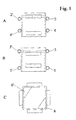
- Each side has two pairs of tubes placed in parallel, horizontally, and same have proportions that do not exceed the length of the side ( Figure 1 ), (C), and they are placed on each side at a same position with respect to its side of the opposing cube (A, B); and the tubes of two of the opposing sides (A) are situated at a different level with respect to the other two sides (B), and the latter are situated closer to the base (1, 1') and closer to the height (3, 3') of the cube than the tubes of its adjoining sides (4, 4') and (2, 2').
- the first mesh of the structure of the welded wire fabric will be situated above the rods of the lower tubes, according to Figure 2 .
- the rods of the lower tubes will be inserted therein in both pieces, connecting both surfaces of the structure (5).
- the mesh is formed by means of arranging bars vertically with other horizontal bars, some on top of others, securing the bonding at the points of contact by welding.
- the rods of the lower tubes will be situated on the same plane and parallel to the lower bars of the mesh, holding the bars perpendicular to the above ones.
- the second mesh has to be positioned in the same way, with the rods installed in the upper tubes which are on the other two sides of the cube (2, 2'). Also, in this way, with the rods on the same plane and in parallel to the lower bars of the mesh.
- rods will be placed and inserted in the upper tubes which are on the same side as the lower tubes, whose rods support the first mesh, and inserted in the two adjacent pieces (3, 3'). It will also be used for anchoring the structure and the mesh is not raised when exerting pressure in an opposite zone.
- the first welded wire fabric is shown only in Figure 3 , and it has to be understood that the second one will be situated superimposed and in the manner that is described.
- the figure shows two joined meshes (I, II) beginning at the joined corners, and it has to be understood that the surfaces of the same are not shown complete in the horizontal direction.
- the other two tubes that are in the structure of the cube, arranged parallel to the upper tubes for the installation of the rods that support the second mesh and in a plane lower than those (4, 4') will be used for the installation of other additional rods when the slab has to support major loads.
- the cube has a lid and a base coated with rustproof paint, and both are assembled by compression to avoid the entrance of the pourable concrete mix.
- the lid is arranged sealed with silicone.
- the lid and base are painted different colors for quickly checking before pouring the concrete whether any of the cubes are in the incorrect position.
- shock absorbers When the concrete has set, the lids of the cubes will be removed, and shock absorbers will then be placed which will make the raising of the slab possible.
- another shock absorber in this case, a highfrequency, Silent block type absorber, will be placed on the bottom, which will facilitate the movement of the shock absorber arranged above same.
Landscapes
- Engineering & Computer Science (AREA)
- Architecture (AREA)
- Civil Engineering (AREA)
- Structural Engineering (AREA)
- Reinforcement Elements For Buildings (AREA)
- On-Site Construction Work That Accompanies The Preparation And Application Of Concrete (AREA)
- Building Environments (AREA)
- Conveying And Assembling Of Building Elements In Situ (AREA)
Abstract
Description
- The technical field of the present invention pertains to a device, which is integrated into the framework of floating slabs, as an instrument for raising the slab once the concrete has set. These floating slabs are arranged in constructions that require an insulation of the central block, as they may be the bases at which are situated electric transformers, air conditioning units, bowling alleys and, generally, sites at which it is desired to avoid the transmission of vibrations and impact noises.
- The system of creating floating slabs by means of distributing metallic containers in welded wire fabric in the form of cubes that are within the forging is known. The raising phase occurs once the concrete has set, and shock-absorbing elements are positioned in the cavity, which are coupled under beveled structures that are located in two of the corners thereof. In this way, the raising of the floating slab will be achieved to the extent desired by means of the pressure of the shock absorbers in its upper part.
- The welded wire fabric is usually formed by two meshes or rebar surfaces, each of which are created by bars that intersect one another at right angles, forming grids, whose points of contact are joined by welding. These are positioned superimposed, trying to align the grids of the two meshes for the correct insertion of cubes which have a height similar to that of the welded wire fabric, and are positioned within the two caps of same so that, after the setting of the concrete, they are close in the forging. For this purpose, a plurality of metallic rods are installed welded on the surface of each cube in the horizontal direction which protrude from their structure. In fixing to the rebar, in order to avoid the displacement thereof in the pouring phase of the concrete, once in the grid, the rods are fastened to the welded wire fabric by means of wires. This involves a lot of work for the operator in the positioning and a limited rigidity of the system, causing the cubes to move when the concrete is poured or by the operator's own movements within the rebar. If the setting occurs with any of these elements displaced or twisted, there will be a weak zone at this point which may cause the fracture of the floating slab in the raising phase.
- The grid of the welded wire fabric is produced by having different proportions. The prior-art system has the drawback that the rods welded to the structure of the cube are arranged so that they cover the grid in every case, to facilitate its bundling by means of wire. For this the operator usually has problems at the time of fitting the cube in the welded wire fabric, and has to shorten the rebar to make a suitable cavity. Apart from the labor-intensive work that it involves, it results in a structure that is hazardous to the work zone, which the ends of the rods welded together with the cuts made in the rebar constitute, with many sharp points, with risk to the operator in the work of positioning the wires or by the fact alone of being situated on the structure.
- The welded wire fabric is manufactured in different extension dimensions for the different positioning sites. For this, the bonding of one surface of the welded wire fabric with those [surfaces] which follow it in the work is necessary. It is equally necessary to fix the corners of the layers of the welded wire fabric, if the last layer goes through zones remote from the center, this force then causes the structure to rise.
- Another type of element is known for arranging in the forging that is made up of a metallic cylinder with walls of considerable size, within which the shock absorber is arranged, having two horizontal projections in its contour for being situated in the rebar. The complexity of this structure makes the manufacture thereof very expensive, and the securing in the welded wire fabric, in spite of the weight that it has, is insufficient.
- The present invention that is proposed fully solves the problems mentioned by presenting a device in the form of a cube which has various horizontal tubes in its perimetral structure, at various levels, suitable for rods being inserted therein, which project from the sides of the cube for placing the different layers of welded wire fabric above them. In this way, the first layer of the welded wire fabric will rest on the rods arranged in the lower tubes of the cube, which are facing on two of its sides; a second welded wire fabric arranged above the rods of the upper tubes, placed on the other two opposite sides of the cube.
- The bonding of the different mesh structures of the work is carried out by means of the rods installed in the lower tubes which support the first welded wire fabric, which connect the cubes of the adjoining mesh surfaces.
- Rods will be placed in the upper tubes parallel to the above tubes for the bonding of two adjacent cubes which are close to the corners of two welded wire fabric surfaces. This upper linking together will prevent the raising of the mesh when a pressure goes or is applied outside of the central zone.
- The object of the present invention is accomplished with a lid and a base for the interior insulation in the pouring of the concrete.
- To complement the description that is being provided and to aid in a better understanding of the features of the present invention, the present specification is accompanied by drawings showing the preferred embodiment, in which, in an illustrative and nonlimiting nature:
-
Figure 1 shows the left elevation (A), front elevation (B) and plan view (C) of the cube that is the subject of the present invention. -
Figure 2 shows a view of the cubes in a first phase of positioning. -
Figure 3 shows us a view of the positioning of the first mesh in the work with two surfaces of same aligned. - Viewing the figures shown, it can be seen how the device for positioning floating slabs is composed of a metallic cube, whose base will have a smaller dimension than the surface of the grid of the mesh and have a height in relation to that of the forging; and in its perimeter it has identical tubes which are preferably attached to the structure by means of welding.
- Each side has two pairs of tubes placed in parallel, horizontally, and same have proportions that do not exceed the length of the side (
Figure 1 ), (C), and they are placed on each side at a same position with respect to its side of the opposing cube (A, B); and the tubes of two of the opposing sides (A) are situated at a different level with respect to the other two sides (B), and the latter are situated closer to the base (1, 1') and closer to the height (3, 3') of the cube than the tubes of its adjoining sides (4, 4') and (2, 2'). - The first mesh of the structure of the welded wire fabric will be situated above the rods of the lower tubes, according to
Figure 2 . - In the adjoining meshes, the rods of the lower tubes will be inserted therein in both pieces, connecting both surfaces of the structure (5).
- The mesh is formed by means of arranging bars vertically with other horizontal bars, some on top of others, securing the bonding at the points of contact by welding. The rods of the lower tubes will be situated on the same plane and parallel to the lower bars of the mesh, holding the bars perpendicular to the above ones.
- The second mesh has to be positioned in the same way, with the rods installed in the upper tubes which are on the other two sides of the cube (2, 2'). Also, in this way, with the rods on the same plane and in parallel to the lower bars of the mesh.
- The separation between the lower tubes and upper tubes for positioning the mesh will be sufficient for the entry of the concrete, on the understanding that there may be little separation that the cavities will have in the pouring which will put the consistency of the future floating slab at risk.
- In the cubes belonging to two mesh surfaces that are located close to the corners, rods will be placed and inserted in the upper tubes which are on the same side as the lower tubes, whose rods support the first mesh, and inserted in the two adjacent pieces (3, 3'). It will also be used for anchoring the structure and the mesh is not raised when exerting pressure in an opposite zone. The first welded wire fabric is shown only in
Figure 3 , and it has to be understood that the second one will be situated superimposed and in the manner that is described. - The figure shows two joined meshes (I, II) beginning at the joined corners, and it has to be understood that the surfaces of the same are not shown complete in the horizontal direction.
- The other two tubes that are in the structure of the cube, arranged parallel to the upper tubes for the installation of the rods that support the second mesh and in a plane lower than those (4, 4') will be used for the installation of other additional rods when the slab has to support major loads.
- The cube has a lid and a base coated with rustproof paint, and both are assembled by compression to avoid the entrance of the pourable concrete mix. As a complement, the lid is arranged sealed with silicone. The lid and base are painted different colors for quickly checking before pouring the concrete whether any of the cubes are in the incorrect position.
- When the concrete has set, the lids of the cubes will be removed, and shock absorbers will then be placed which will make the raising of the slab possible. In this most suitable embodiment, another shock absorber, in this case, a highfrequency, Silent block type absorber, will be placed on the bottom, which will facilitate the movement of the shock absorber arranged above same.
- It should be understood that the present invention was described according to the preferred embodiment of same; therefore, it may be susceptible to modifications in shape, size and materials, provided that said changes do not substantially vary the features of the present invention as they are claimed below.
Claims (10)
- Device for the positioning of floating slabs and the Installation system thereof, arranged in welded wire fabric and suitable, after the setting of concrete, for accommodating shock absorbers in the lifting phase of the forging, characterized in that the device is in the shape of a cube, the base dimensions of which are less than the grid of the mesh, and whose height is integral with that of the forging, with horizontal tubes on its sides, whose length is less than that of the side of the cube, and with a cross section suitable for the insertion of rods.
- Device for positioning floating slabs in accordance with the above claim, characterized in that there are two tubes that are arranged on each side, and they are positioned on each side in a same position with respect to the side of the opposing cube (A, B).
- Device for positioning floating slabs in accordance with the above claims, characterized in that the upper and lower tubes of two of the sides are located close the lid (3, 3') and close the base (1, 1'), respectively.
- Device for positioning floating slabs in accordance with the above claims, characterized in that on the other two sides the upper tube is located in a position lower than the upper tube of its adjoining sides (2, 2') and the lower tube is located in a position higher than the lower tubes of its adjoining sides (4, 4').
- Device for positioning floating slabs and system for the installation thereof in accordance with claim 1, characterized in that the meshes will be positioned such that their upper bars are perpendicular to the rods and above same.
- Device for positioning floating slabs and system for the installation thereof in accordance with claim 1, characterized in that the first mesh will be positioned above the rods arranged on the sides of the cube which have the tubes closest to the base (1, 1').
- Device for positioning floating slabs and system for the installation thereof in accordance with the above claim, characterized in that for the bonding of two joined mesh surfaces, the rod will be inserted in the two adjacent cubes of the mesh surfaces (5).
- Device for positioning floating slabs and system for the installation thereof in accordance with the above claims, characterized in that the second mesh will be positioned above the rods of the upper tubes of the other two sides of the cube (2, 2').
- Device for positioning floating slabs and system for the installation thereof in accordance with claim 1, characterized in that rods will be arranged in the lower tubes of the other two sides of the cube when major loads are expected to be supported by the floating slab (4, 4').
- Device for positioning floating slabs and system for installation thereof in accordance with claim 1, characterized in that in the cubes next to the corners of two mesh surfaces, a rod will link the adjoining cubes, arranged in the upper tubes parallel to the tube at which the first mesh (3, 3') has been positioned.
Applications Claiming Priority (2)
| Application Number | Priority Date | Filing Date | Title |
|---|---|---|---|
| ES200701966A ES2315182B1 (en) | 2007-07-13 | 2007-07-13 | DEVICE FOR PLACEMENT ON FLOATING Slabs AND ITS INSTALLATION SYSTEM. |
| PCT/ES2008/000469 WO2009010608A1 (en) | 2007-07-13 | 2008-07-01 | Device for laying floating flagstones and installation system thereof |
Publications (3)
| Publication Number | Publication Date |
|---|---|
| EP2202367A1 true EP2202367A1 (en) | 2010-06-30 |
| EP2202367A4 EP2202367A4 (en) | 2011-11-16 |
| EP2202367B1 EP2202367B1 (en) | 2018-06-27 |
Family
ID=40259343
Family Applications (1)
| Application Number | Title | Priority Date | Filing Date |
|---|---|---|---|
| EP08805299.8A Active EP2202367B1 (en) | 2007-07-13 | 2008-07-01 | Device for positioning floating concrete slabs |
Country Status (4)
| Country | Link |
|---|---|
| US (1) | US20100281815A1 (en) |
| EP (1) | EP2202367B1 (en) |
| ES (2) | ES2315182B1 (en) |
| WO (1) | WO2009010608A1 (en) |
Cited By (1)
| Publication number | Priority date | Publication date | Assignee | Title |
|---|---|---|---|---|
| WO2025046154A1 (en) | 2023-08-30 | 2025-03-06 | Tejasa-Tc, S.L. | Earthquake-resistant structure |
Families Citing this family (5)
| Publication number | Priority date | Publication date | Assignee | Title |
|---|---|---|---|---|
| WO2013181565A1 (en) * | 2012-05-31 | 2013-12-05 | Wayne State University | Self-confining ceramic articles using advanced material reinforcements and method of manufacture |
| US20140331592A1 (en) * | 2013-05-09 | 2014-11-13 | Lloyd L. Lawrence | Rebar securing device |
| ES2644754B1 (en) * | 2016-04-29 | 2018-09-13 | Tejasa-Tc, S.L.L. | ANTISISM PROTECTION SYSTEM FOR A FLOATING Slab. |
| ES2668978B1 (en) | 2016-10-21 | 2018-11-20 | Tejasa-Tc, S.L.L. | ANTIVIBRATORY SUPPORT SYSTEM. |
| CN208347085U (en) * | 2018-05-23 | 2019-01-08 | 阳程(佛山)科技有限公司 | Cement plate |
Family Cites Families (16)
| Publication number | Priority date | Publication date | Assignee | Title |
|---|---|---|---|---|
| US1070921A (en) * | 1912-07-16 | 1913-08-19 | John T Saltiel | Concrete building construction. |
| GB466044A (en) * | 1935-11-28 | 1937-05-21 | Arthur Felix Dufton | Improvements in or relating to the construction of sound insulating floors and the like |
| SE310412B (en) * | 1965-09-24 | 1969-04-28 | O Andersen | |
| FR1530386A (en) * | 1967-07-07 | 1968-06-21 | Trefileries Du Sud Est | Perfected pallet with removable feet instantly adaptable |
| ES181674Y (en) * | 1969-11-24 | 1974-03-16 | Monzon Indave | SHOCK ABSORBER FOR VIBRATIONS AND IMPACTS. |
| US4793104A (en) * | 1988-06-15 | 1988-12-27 | Delberg, Inc. | Guide for laying glass blocks |
| DE4012493C2 (en) * | 1990-04-19 | 2000-06-08 | Continental Ag | Floating floor and process for its manufacture |
| FR2682412B1 (en) * | 1991-10-10 | 1993-11-26 | Lacroix Alain | A DEVICE OF VISITABLE, REMOVABLE AND ADJUSTABLE SPRING BOXES FOR LOW FREQUENCY FILTERING OF FLOATING FLOORS. |
| DK172957B1 (en) * | 1994-06-30 | 1999-10-18 | Henning Baltzer Rasmussen | Spacer means and method of manufacture thereof |
| US6282860B1 (en) * | 1998-05-08 | 2001-09-04 | Jose G. Ramirez | Wire mesh support |
| US7204064B2 (en) * | 2000-02-18 | 2007-04-17 | Sergio Cazzolaro | Structures which can be dismantled and folded, consisting of interconnecting tubular elements |
| JP4097894B2 (en) * | 2000-12-28 | 2008-06-11 | 早川ゴム株式会社 | Soundproof floor structure, soundproof flooring, and construction method of soundproof floor structure |
| DE60121960T2 (en) * | 2001-10-08 | 2007-02-15 | Lacroix, Alain Serge Charles | Apparatus for low frequency filtering of floating floors |
| US7108453B2 (en) * | 2002-04-19 | 2006-09-19 | Harris Terry L | Support for concrete reinforcing members |
| CN1297712C (en) * | 2004-07-23 | 2007-01-31 | 尹学军 | Floating road bed |
| US20080028718A1 (en) * | 2006-08-02 | 2008-02-07 | Erickson John A | Stackable rebar support chair |
-
2007
- 2007-07-13 ES ES200701966A patent/ES2315182B1/en not_active Expired - Fee Related
-
2008
- 2008-07-01 EP EP08805299.8A patent/EP2202367B1/en active Active
- 2008-07-01 ES ES08805299.8T patent/ES2687652T3/en active Active
- 2008-07-01 US US12/668,890 patent/US20100281815A1/en not_active Abandoned
- 2008-07-01 WO PCT/ES2008/000469 patent/WO2009010608A1/en not_active Ceased
Cited By (1)
| Publication number | Priority date | Publication date | Assignee | Title |
|---|---|---|---|---|
| WO2025046154A1 (en) | 2023-08-30 | 2025-03-06 | Tejasa-Tc, S.L. | Earthquake-resistant structure |
Also Published As
| Publication number | Publication date |
|---|---|
| ES2315182B1 (en) | 2009-11-11 |
| EP2202367B1 (en) | 2018-06-27 |
| EP2202367A4 (en) | 2011-11-16 |
| ES2315182A1 (en) | 2009-03-16 |
| US20100281815A1 (en) | 2010-11-11 |
| ES2687652T3 (en) | 2018-10-26 |
| WO2009010608A1 (en) | 2009-01-22 |
Similar Documents
| Publication | Publication Date | Title |
|---|---|---|
| US8505267B2 (en) | Holder for being positioned in floating floor slabs and installation system thereof | |
| EP2202367A1 (en) | Device for laying floating flagstones and installation system thereof | |
| KR102056406B1 (en) | Half pc slab and producing method thereof | |
| KR101246268B1 (en) | Structure of gabion wall with vegetation steel frame and constructing method thereof | |
| JP6983533B2 (en) | Construction method of steel-concrete composite structure and steel-concrete composite structure | |
| KR101019302B1 (en) | Gabion, gabion making method and construction method using gabion | |
| KR20130111862A (en) | Precast concrete panel having upper protuberant concrete beam | |
| ES2533339T3 (en) | Formwork modules, assembled and disposable, to build modular formwork to make concrete foundations | |
| US10640970B2 (en) | Concrete building elements and assemblies thereof, and related methods | |
| KR20150114299A (en) | Apparatus for manufacturing and assembling reinforcing steel bar net and construction method of foundation reinforcement using the same | |
| KR20170013009A (en) | Method for constructing junction between the double wall Precast Concretes and the junction structure thereof, the construction method for underground parking using he double wall Precast Concrete, and construction method for the rainwater storage using he double wall Precast Concrete | |
| KR101827381B1 (en) | Multi-layer construction structure of the structure using double-wall PC and construction method thereof | |
| CN105102734A (en) | Hybrid structure and construction method for same | |
| KR101828341B1 (en) | Plate type wall structure and its construction method | |
| KR101588115B1 (en) | Prefab double wall using truss deck and manufacturing method thereof | |
| EP2582503B1 (en) | Mould for the construction of a protection and securing element of the mattress type | |
| KR101748781B1 (en) | Precast wall structure construction method | |
| KR100403989B1 (en) | Bridge slab construction method and precast concrete plate applied therein | |
| KR101229086B1 (en) | Mold board of slab opening that i do not need short pillar | |
| KR102409371B1 (en) | Rib-type PC slab having welded wire mesh with upper end hook and method for manufacturing and construction of the rib-type PC slab | |
| JP3180333U (en) | Precast concrete foundation block | |
| JPH11107293A (en) | Foundation structure of building, foundation construction method, and block for foundation | |
| JP5960016B2 (en) | Concrete foundation construction set | |
| KR20010095899A (en) | Composition of precast concrete wall and precast concrete column for outdoor to sustain external force | |
| JP3180332U (en) | Concrete foundation construction set |
Legal Events
| Date | Code | Title | Description |
|---|---|---|---|
| PUAI | Public reference made under article 153(3) epc to a published international application that has entered the european phase |
Free format text: ORIGINAL CODE: 0009012 |
|
| 17P | Request for examination filed |
Effective date: 20100210 |
|
| AK | Designated contracting states |
Kind code of ref document: A1 Designated state(s): AT BE BG CH CY CZ DE DK EE ES FI FR GB GR HR HU IE IS IT LI LT LU LV MC MT NL NO PL PT RO SE SI SK TR |
|
| AX | Request for extension of the european patent |
Extension state: AL BA MK RS |
|
| DAX | Request for extension of the european patent (deleted) | ||
| A4 | Supplementary search report drawn up and despatched |
Effective date: 20111019 |
|
| RIC1 | Information provided on ipc code assigned before grant |
Ipc: E04C 5/20 20060101ALI20111013BHEP Ipc: E04C 5/18 20060101ALI20111013BHEP Ipc: E04F 15/22 20060101AFI20111013BHEP |
|
| GRAP | Despatch of communication of intention to grant a patent |
Free format text: ORIGINAL CODE: EPIDOSNIGR1 |
|
| INTG | Intention to grant announced |
Effective date: 20171201 |
|
| GRAJ | Information related to disapproval of communication of intention to grant by the applicant or resumption of examination proceedings by the epo deleted |
Free format text: ORIGINAL CODE: EPIDOSDIGR1 |
|
| GRAP | Despatch of communication of intention to grant a patent |
Free format text: ORIGINAL CODE: EPIDOSNIGR1 |
|
| INTC | Intention to grant announced (deleted) | ||
| INTG | Intention to grant announced |
Effective date: 20180411 |
|
| GRAS | Grant fee paid |
Free format text: ORIGINAL CODE: EPIDOSNIGR3 |
|
| GRAA | (expected) grant |
Free format text: ORIGINAL CODE: 0009210 |
|
| AK | Designated contracting states |
Kind code of ref document: B1 Designated state(s): AT BE BG CH CY CZ DE DK EE ES FI FR GB GR HR HU IE IS IT LI LT LU LV MC MT NL NO PL PT RO SE SI SK TR |
|
| REG | Reference to a national code |
Ref country code: GB Ref legal event code: FG4D |
|
| REG | Reference to a national code |
Ref country code: AT Ref legal event code: REF Ref document number: 1012497 Country of ref document: AT Kind code of ref document: T Effective date: 20180715 |
|
| REG | Reference to a national code |
Ref country code: IE Ref legal event code: FG4D |
|
| REG | Reference to a national code |
Ref country code: DE Ref legal event code: R096 Ref document number: 602008055779 Country of ref document: DE |
|
| REG | Reference to a national code |
Ref country code: FR Ref legal event code: PLFP Year of fee payment: 11 |
|
| REG | Reference to a national code |
Ref country code: ES Ref legal event code: FG2A Ref document number: 2687652 Country of ref document: ES Kind code of ref document: T3 Effective date: 20181026 |
|
| PG25 | Lapsed in a contracting state [announced via postgrant information from national office to epo] |
Ref country code: NO Free format text: LAPSE BECAUSE OF FAILURE TO SUBMIT A TRANSLATION OF THE DESCRIPTION OR TO PAY THE FEE WITHIN THE PRESCRIBED TIME-LIMIT Effective date: 20180927 Ref country code: LT Free format text: LAPSE BECAUSE OF FAILURE TO SUBMIT A TRANSLATION OF THE DESCRIPTION OR TO PAY THE FEE WITHIN THE PRESCRIBED TIME-LIMIT Effective date: 20180627 Ref country code: SE Free format text: LAPSE BECAUSE OF FAILURE TO SUBMIT A TRANSLATION OF THE DESCRIPTION OR TO PAY THE FEE WITHIN THE PRESCRIBED TIME-LIMIT Effective date: 20180627 Ref country code: BG Free format text: LAPSE BECAUSE OF FAILURE TO SUBMIT A TRANSLATION OF THE DESCRIPTION OR TO PAY THE FEE WITHIN THE PRESCRIBED TIME-LIMIT Effective date: 20180927 Ref country code: FI Free format text: LAPSE BECAUSE OF FAILURE TO SUBMIT A TRANSLATION OF THE DESCRIPTION OR TO PAY THE FEE WITHIN THE PRESCRIBED TIME-LIMIT Effective date: 20180627 |
|
| REG | Reference to a national code |
Ref country code: NL Ref legal event code: MP Effective date: 20180627 |
|
| REG | Reference to a national code |
Ref country code: LT Ref legal event code: MG4D |
|
| PG25 | Lapsed in a contracting state [announced via postgrant information from national office to epo] |
Ref country code: LV Free format text: LAPSE BECAUSE OF FAILURE TO SUBMIT A TRANSLATION OF THE DESCRIPTION OR TO PAY THE FEE WITHIN THE PRESCRIBED TIME-LIMIT Effective date: 20180627 Ref country code: HR Free format text: LAPSE BECAUSE OF FAILURE TO SUBMIT A TRANSLATION OF THE DESCRIPTION OR TO PAY THE FEE WITHIN THE PRESCRIBED TIME-LIMIT Effective date: 20180627 Ref country code: GR Free format text: LAPSE BECAUSE OF FAILURE TO SUBMIT A TRANSLATION OF THE DESCRIPTION OR TO PAY THE FEE WITHIN THE PRESCRIBED TIME-LIMIT Effective date: 20180928 |
|
| REG | Reference to a national code |
Ref country code: AT Ref legal event code: MK05 Ref document number: 1012497 Country of ref document: AT Kind code of ref document: T Effective date: 20180627 |
|
| PG25 | Lapsed in a contracting state [announced via postgrant information from national office to epo] |
Ref country code: NL Free format text: LAPSE BECAUSE OF FAILURE TO SUBMIT A TRANSLATION OF THE DESCRIPTION OR TO PAY THE FEE WITHIN THE PRESCRIBED TIME-LIMIT Effective date: 20180627 |
|
| PG25 | Lapsed in a contracting state [announced via postgrant information from national office to epo] |
Ref country code: AT Free format text: LAPSE BECAUSE OF FAILURE TO SUBMIT A TRANSLATION OF THE DESCRIPTION OR TO PAY THE FEE WITHIN THE PRESCRIBED TIME-LIMIT Effective date: 20180627 Ref country code: IS Free format text: LAPSE BECAUSE OF FAILURE TO SUBMIT A TRANSLATION OF THE DESCRIPTION OR TO PAY THE FEE WITHIN THE PRESCRIBED TIME-LIMIT Effective date: 20181027 Ref country code: PL Free format text: LAPSE BECAUSE OF FAILURE TO SUBMIT A TRANSLATION OF THE DESCRIPTION OR TO PAY THE FEE WITHIN THE PRESCRIBED TIME-LIMIT Effective date: 20180627 Ref country code: SK Free format text: LAPSE BECAUSE OF FAILURE TO SUBMIT A TRANSLATION OF THE DESCRIPTION OR TO PAY THE FEE WITHIN THE PRESCRIBED TIME-LIMIT Effective date: 20180627 Ref country code: CZ Free format text: LAPSE BECAUSE OF FAILURE TO SUBMIT A TRANSLATION OF THE DESCRIPTION OR TO PAY THE FEE WITHIN THE PRESCRIBED TIME-LIMIT Effective date: 20180627 Ref country code: RO Free format text: LAPSE BECAUSE OF FAILURE TO SUBMIT A TRANSLATION OF THE DESCRIPTION OR TO PAY THE FEE WITHIN THE PRESCRIBED TIME-LIMIT Effective date: 20180627 Ref country code: EE Free format text: LAPSE BECAUSE OF FAILURE TO SUBMIT A TRANSLATION OF THE DESCRIPTION OR TO PAY THE FEE WITHIN THE PRESCRIBED TIME-LIMIT Effective date: 20180627 |
|
| PG25 | Lapsed in a contracting state [announced via postgrant information from national office to epo] |
Ref country code: IT Free format text: LAPSE BECAUSE OF FAILURE TO SUBMIT A TRANSLATION OF THE DESCRIPTION OR TO PAY THE FEE WITHIN THE PRESCRIBED TIME-LIMIT Effective date: 20180627 |
|
| REG | Reference to a national code |
Ref country code: CH Ref legal event code: PL |
|
| REG | Reference to a national code |
Ref country code: DE Ref legal event code: R097 Ref document number: 602008055779 Country of ref document: DE |
|
| PG25 | Lapsed in a contracting state [announced via postgrant information from national office to epo] |
Ref country code: LU Free format text: LAPSE BECAUSE OF NON-PAYMENT OF DUE FEES Effective date: 20180701 Ref country code: MC Free format text: LAPSE BECAUSE OF FAILURE TO SUBMIT A TRANSLATION OF THE DESCRIPTION OR TO PAY THE FEE WITHIN THE PRESCRIBED TIME-LIMIT Effective date: 20180627 |
|
| REG | Reference to a national code |
Ref country code: BE Ref legal event code: MM Effective date: 20180731 |
|
| REG | Reference to a national code |
Ref country code: IE Ref legal event code: MM4A |
|
| PG25 | Lapsed in a contracting state [announced via postgrant information from national office to epo] |
Ref country code: LI Free format text: LAPSE BECAUSE OF NON-PAYMENT OF DUE FEES Effective date: 20180731 Ref country code: CH Free format text: LAPSE BECAUSE OF NON-PAYMENT OF DUE FEES Effective date: 20180731 Ref country code: IE Free format text: LAPSE BECAUSE OF NON-PAYMENT OF DUE FEES Effective date: 20180701 |
|
| PLBE | No opposition filed within time limit |
Free format text: ORIGINAL CODE: 0009261 |
|
| STAA | Information on the status of an ep patent application or granted ep patent |
Free format text: STATUS: NO OPPOSITION FILED WITHIN TIME LIMIT |
|
| GBPC | Gb: european patent ceased through non-payment of renewal fee |
Effective date: 20180927 |
|
| PG25 | Lapsed in a contracting state [announced via postgrant information from national office to epo] |
Ref country code: BE Free format text: LAPSE BECAUSE OF NON-PAYMENT OF DUE FEES Effective date: 20180731 Ref country code: DK Free format text: LAPSE BECAUSE OF FAILURE TO SUBMIT A TRANSLATION OF THE DESCRIPTION OR TO PAY THE FEE WITHIN THE PRESCRIBED TIME-LIMIT Effective date: 20180627 |
|
| 26N | No opposition filed |
Effective date: 20190328 |
|
| PG25 | Lapsed in a contracting state [announced via postgrant information from national office to epo] |
Ref country code: SI Free format text: LAPSE BECAUSE OF FAILURE TO SUBMIT A TRANSLATION OF THE DESCRIPTION OR TO PAY THE FEE WITHIN THE PRESCRIBED TIME-LIMIT Effective date: 20180627 |
|
| PG25 | Lapsed in a contracting state [announced via postgrant information from national office to epo] |
Ref country code: GB Free format text: LAPSE BECAUSE OF NON-PAYMENT OF DUE FEES Effective date: 20180927 |
|
| PG25 | Lapsed in a contracting state [announced via postgrant information from national office to epo] |
Ref country code: MT Free format text: LAPSE BECAUSE OF NON-PAYMENT OF DUE FEES Effective date: 20180701 |
|
| PG25 | Lapsed in a contracting state [announced via postgrant information from national office to epo] |
Ref country code: HU Free format text: LAPSE BECAUSE OF FAILURE TO SUBMIT A TRANSLATION OF THE DESCRIPTION OR TO PAY THE FEE WITHIN THE PRESCRIBED TIME-LIMIT; INVALID AB INITIO Effective date: 20080701 Ref country code: PT Free format text: LAPSE BECAUSE OF FAILURE TO SUBMIT A TRANSLATION OF THE DESCRIPTION OR TO PAY THE FEE WITHIN THE PRESCRIBED TIME-LIMIT Effective date: 20180627 |
|
| PG25 | Lapsed in a contracting state [announced via postgrant information from national office to epo] |
Ref country code: CY Free format text: LAPSE BECAUSE OF FAILURE TO SUBMIT A TRANSLATION OF THE DESCRIPTION OR TO PAY THE FEE WITHIN THE PRESCRIBED TIME-LIMIT Effective date: 20180627 |
|
| PGFP | Annual fee paid to national office [announced via postgrant information from national office to epo] |
Ref country code: DE Payment date: 20221228 Year of fee payment: 15 |
|
| REG | Reference to a national code |
Ref country code: DE Ref legal event code: R119 Ref document number: 602008055779 Country of ref document: DE |
|
| PG25 | Lapsed in a contracting state [announced via postgrant information from national office to epo] |
Ref country code: DE Free format text: LAPSE BECAUSE OF NON-PAYMENT OF DUE FEES Effective date: 20240201 |
|
| PGFP | Annual fee paid to national office [announced via postgrant information from national office to epo] |
Ref country code: TR Payment date: 20250613 Year of fee payment: 18 |
|
| PGFP | Annual fee paid to national office [announced via postgrant information from national office to epo] |
Ref country code: ES Payment date: 20250802 Year of fee payment: 18 |
|
| PGFP | Annual fee paid to national office [announced via postgrant information from national office to epo] |
Ref country code: FR Payment date: 20250717 Year of fee payment: 18 |