KR102354464B1 - Multi-rib PC slab having welded wire mesh and method for manufacturing and construction of the multi-rib PC slab - Google Patents
Multi-rib PC slab having welded wire mesh and method for manufacturing and construction of the multi-rib PC slab Download PDFInfo
- Publication number
- KR102354464B1 KR102354464B1 KR1020200156757A KR20200156757A KR102354464B1 KR 102354464 B1 KR102354464 B1 KR 102354464B1 KR 1020200156757 A KR1020200156757 A KR 1020200156757A KR 20200156757 A KR20200156757 A KR 20200156757A KR 102354464 B1 KR102354464 B1 KR 102354464B1
- Authority
- KR
- South Korea
- Prior art keywords
- wire mesh
- shear
- reinforcing bars
- horizontal
- slab
- Prior art date
Links
Images


Classifications
-
- E—FIXED CONSTRUCTIONS
- E04—BUILDING
- E04B—GENERAL BUILDING CONSTRUCTIONS; WALLS, e.g. PARTITIONS; ROOFS; FLOORS; CEILINGS; INSULATION OR OTHER PROTECTION OF BUILDINGS
- E04B5/00—Floors; Floor construction with regard to insulation; Connections specially adapted therefor
- E04B5/16—Load-carrying floor structures wholly or partly cast or similarly formed in situ
- E04B5/17—Floor structures partly formed in situ
- E04B5/23—Floor structures partly formed in situ with stiffening ribs or other beam-like formations wholly or partly prefabricated
-
- E—FIXED CONSTRUCTIONS
- E04—BUILDING
- E04C—STRUCTURAL ELEMENTS; BUILDING MATERIALS
- E04C5/00—Reinforcing elements, e.g. for concrete; Auxiliary elements therefor
- E04C5/01—Reinforcing elements of metal, e.g. with non-structural coatings
-
- E—FIXED CONSTRUCTIONS
- E04—BUILDING
- E04C—STRUCTURAL ELEMENTS; BUILDING MATERIALS
- E04C5/00—Reinforcing elements, e.g. for concrete; Auxiliary elements therefor
- E04C5/01—Reinforcing elements of metal, e.g. with non-structural coatings
- E04C5/06—Reinforcing elements of metal, e.g. with non-structural coatings of high bending resistance, i.e. of essentially three-dimensional extent, e.g. lattice girders
Abstract
Description
본 발명은 용접철망을 구비하는 멀티리브 PC 슬래브 및 멀티리브 PC 슬래브의 제작 및 시공 방법에 관한 것으로서, 더욱 상세하게는 리브부의 내부에 매립되고 슬래브부 위까지 노출되는 전단철근으로서 자동용접된 철망을 사용하여 수평철망과 함께 배근하여 전단 강도가 우수한 멀티리브 PC 슬래브를 제작하고, 이를 이용하여 현장배근철망을 수평하게 배치하고 콘크리트를 타설하여 멀티리브 슬래브를 쉽게 시공할 수 있는 용접철망을 구비하는 멀티리브 PC 슬래브 및 멀티리브 PC 슬래브의 제작 및 시공 방법에 관한 것이다.The present invention relates to a multi-rib PC slab having a welded wire mesh and a method for manufacturing and constructing a multi-rib PC slab, and more particularly, to a wire mesh automatically welded as shear reinforcement embedded in a rib part and exposed up to the slab part. Multi-ribbed PC slab with excellent shear strength is produced by using horizontal wire mesh to build a multi-ribbed PC slab with a welded wire mesh that allows for easy construction of multi-rib slabs by horizontally arranging the on-site reinforcement wire mesh and pouring concrete. It relates to a method of manufacturing and constructing a rib PC slab and a multi-rib PC slab.
일반적으로 철근 콘크리트 구조물은 기둥, 보, 슬래브의 주요 구조부로 이루어지고, 기둥은 주로 압축을 받지만 후프를 배치하여 전단력에 저항한다.In general, reinforced concrete structures consist of the main structural parts of columns, beams, and slabs, and the columns are mainly subjected to compression, but resist shear forces by arranging hoops.
보와 슬래브는 주로 휨재로서 거동하며 전단력도 동시에 받고 특히 보 부재의 수직방향 혹은 균열의 직각방향으로 철근을 배치하여 전단에 저항하며 이것을 전단철근이라 명명한다.Beams and slabs mainly behave as flexural materials and receive shear force at the same time and resist shear by arranging reinforcing bars in the vertical direction of the beam member or perpendicular to the cracks, and this is called shear reinforcing bars.
이러한 전단철근은 주근과 달리 가닥이 많으며 단부로 갈수록 많이 배치되고 전단철근은 그 수만큼 작업자의 품과 철근 자재의 가공비, 간격의 정확도, 타설시 작업성 등에 큰 영향을 준다.Unlike the main bars, these shear reinforcing bars have many strands and are placed more toward the end, and the number of shear reinforcing bars greatly affects the width of the worker, the processing cost of the reinforcing bar material, the accuracy of spacing, and workability when placing.
특히, 공장에서 제작하는 프리캐스트 콘크리트(PC: Precast Concrete) 슬래브의 경우, 보 역할을 하는 리브의 개수에 따라 리브가 한 개인 싱글티, 리브가 두 개인 더블티, 세 개인 트라이티, 네 개 이상인 멀티리브 부재로 분류될 수 있다. 이러한 리브나 보에 전단철근들을 가공배치하여 수작업으로 하나하나 엮는 것은 엄청난 부담이 된다.In particular, in the case of precast concrete (PC: Precast Concrete) slabs manufactured at the factory, depending on the number of ribs acting as beams, single tee with one rib, double tee with two ribs, triti with three, and multi rib with four or more can be classified as absent. It is a huge burden to process and place shear reinforcing bars on these ribs or beams and weave them one by one by hand.
또한, 구조 기준에 의하면 이러한 전단철근은 길이방향의 주철근을 표준후크로 감싸거나 용접처리하여 충분히 정착되어 내력을 발휘하도록 요구하고 있다. PC공법에서 사용하는 리브형 슬래브는 리브의 폭이 좁아 전단철근을 후크 형태로 가공하여 주근을 감싸기 어려워 구조 기준에서는 예외 조항을 두기도 한다. 하지만 춤이 깊은 더블티 슬래브와 같이 리브의 상하 길이가 긴 경우에는 이러한 예외 조항도 적용하기 어려운 것이 현실이다.In addition, according to the structural standards, such shear reinforcing bars are required to be sufficiently settled and to exhibit proof strength by wrapping the main reinforcing bars in the longitudinal direction with standard hooks or welding them. The ribbed slab used in the PC method has a narrow rib width, so it is difficult to wrap the main bars by processing shear reinforcing bars into hooks, so there are exceptions in the structural standards. However, in the case of a long rib, such as a deep double tee slab, it is difficult to apply this exception.
즉, 이러한 보의 전단철근을 가공 배치하여 모든 것을 해결할 수 있는 방법은 전단철근의 상하부를 용접처리하고 하나하나의 전단철근을 기계화 제작하는 방법 밖에 없다. 기존의 일정한 간격으로 자동용접된 기성품 와이어메쉬를 사용하는 것은 수평 휨 슬래브 철근으로는 적합하지만, 수직 전단철근으로 세워서 사용하는 것은 적절하지 않다.That is, the only way to solve everything by processing and arranging the shear reinforcement of such a beam is to weld the upper and lower parts of the shear reinforcement and mechanize each shear reinforcement. It is appropriate to use the existing wire mesh automatically welded at regular intervals as a horizontal bending slab reinforcing bar, but it is not appropriate to use it standing up as a vertical shear reinforcing bar.
도 1은 종래기술에 따른 멀티리브 PC 슬래브를 나타내는 일부 사시도이다.1 is a partial perspective view showing a multi-rib PC slab according to the prior art.
종래의 멀티리브 PC 슬래브(10)는 한 쌍의 리브를 구비하는 더블티 슬래브로서, 각 리브부의 하부에 수평하게 배치되는 주근(20)과, 슬래브부에 수평하게 배치되는 수평철근(30)과, 하단이 주근(20)을 감싸도록 결합되고 폭방향으로 절곡된 상단부가 슬래브부의 상면에서 노출되도록 수직으로 배치되는 복수의 후크철근(50)을 포함한다.The conventional
수평철근(30)은 복수의 가로철근(32)과 복수의 세로철근(34)이 소정 간격으로 배치되고, 서로 철사 등에 의해 결합될 수 있다.In the
후크철근(50)은 상단부가 폭방향으로 절곡되고 슬래브부의 상면에서 수직으로 노출되는 전단철근이다. 후크철근(50)의 하단은 주근(20)을 감싸도록 형성되고 추가적으로 철사로 결합할 수 있다. 후크철근(50)의 중단은 수평철근(30)에 철사로 결합될 수 있다.The
그런데, 종래의 멀티리브 PC 슬래브(10)를 제작하려면, 복수의 가로철근(32)과 복수의 세로철근(34)을 서로 연결하는 작업이 필요할 뿐만 아니라, 복수의 후크철근(50)을 주근(20)과 수평철근(30)에 일일이 연결하는 작업이 필요하다.By the way, in order to manufacture the conventional
그래서, 종래의 멀티리브 PC 슬래브는 제작하기가 매우 번거롭고, 복수의 후크철근(50)이 직접적으로 연결되지 않기 때문에 전단 강도도 약한 문제점이 있다.So, the conventional multi-rib PC slab is very cumbersome to manufacture, and since the plurality of
본 발명은 복수의 리브부를 구비하는 PC 슬래브를 이용하여 강도가 우수한 슬래브 구조물, 특히 전단 강도가 우수한 슬래브 구조물을 제작 및 시공할 수 있는 멀티리브 PC 슬래브 및 멀티리브 PC 슬래브의 제작 및 시공 방법을 제공하는 것을 목적으로 한다.The present invention provides a multi-rib PC slab and a method for manufacturing and constructing a multi-rib PC slab capable of manufacturing and constructing a slab structure having excellent strength, particularly a slab structure having excellent shear strength, using a PC slab having a plurality of ribs aim to do
상기 목적을 달성하기 위한 본 발명의 용접철망을 구비하는 멀티리브 PC 슬래브는, 평판 형태의 슬래브부; 상기 슬래브부의 하면에 소정 간격으로 일체로 형성되는 복수의 리브부; 각 리브부의 내부에 매립되고 상단부가 상기 슬래브부의 상면에서 돌출되도록 배치되는 복수의 전단철망; 및 상기 슬래브부의 내부에 매립되고 상기 복수의 전단철망에 결속되는 수평철망을 포함하고, 상기 수평철망에서 상기 전단철망의 외측에는 복수의 가로철근에 복수의 결속철근이 결합된다.Multi-rib PC slab having a welded wire mesh of the present invention for achieving the above object, a slab portion in the form of a flat plate; a plurality of ribs integrally formed on a lower surface of the slab at predetermined intervals; a plurality of shear wire meshes embedded in each rib part and disposed so that the upper end protrudes from the upper surface of the slab part; and a horizontal wire mesh embedded in the interior of the slab and bound to the plurality of shear wire meshes, wherein a plurality of binding reinforcing bars are coupled to the plurality of transverse reinforcing bars on the outside of the shear wire mesh in the horizontal wire mesh.
상기 전단철망은 수직으로 배치되는 복수의 전단철근과, 상기 복수의 전단철근의 일측에 용접되는 복수의 수평철근을 포함할 수 있다.The shear wire mesh may include a plurality of shear reinforcing bars disposed vertically, and a plurality of horizontal reinforcing bars welded to one side of the plurality of shear reinforcing bars.
상기 수평철근은 상기 복수의 전단철근의 하단 일측에 용접되는 하부정착근과, 상기 복수의 전단철근의 상부 일측에 용접되어 상기 수평철망에 결합되는 위치고정근과, 상기 복수의 전단철근의 상단 일측에 용접되어 현장배근철망을 지지하는 상부정착근을 포함할 수 있다.The horizontal reinforcing bar includes a lower anchoring reinforcing bar welded to one lower end of the plurality of shear reinforcing bars, a position fixing reinforcing bar welded to an upper side of the plurality of shear reinforcing bars and coupled to the horizontal wire mesh, and welding to one upper end of the plurality of shear reinforcing bars. It may include upper anchoring reinforcing bars to support the field reinforcement wire mesh.
상기 수평철근은 상기 리브부가 높은 경우 상기 복수의 전단철근의 하부 일측에 용접되는 리브복부근을 더 포함할 수 있다.The horizontal reinforcing bar may further include a rib abdominal reinforcing bar that is welded to one lower side of the plurality of shear reinforcing bars when the rib portion is high.
상기 위치고정근과 상기 리브복부근은 상기 전단철근과 동일한 직경(D1)을 가지고, 상기 상부정착근은 상기 전단철근의 직경(D1)보다 큰 직경(D2)을 가지며, 상기 하부정착근은 상기 상부정착근의 직경(D2)보다 큰 직경(D3)을 가질 수 있다.The position fixing muscle and the rib abdominal muscle have the same diameter (D1) as the shear reinforcement, the upper anchoring muscle has a larger diameter (D2) than the diameter (D1) of the shear reinforcement, and the lower anchoring muscle is the upper anchoring muscle It may have a diameter (D3) greater than the diameter (D2) of the root.
상기 복수의 결속철근은 복수의 세로철근과 복수의 가로철근이 용접된 결속철망일 수 있다.The plurality of binding reinforcing bars may be a binding wire mesh in which a plurality of vertical reinforcing bars and a plurality of horizontal reinforcing bars are welded.
상기 위치고정근은 상기 수평철망의 상면에 지지되도록 결합될 수 있다.The positioning muscle may be coupled to be supported on the upper surface of the horizontal wire mesh.
상기 위치고정근은 상기 수평철망을 하면에서 지지하도록 결합될 수 있다.The positioning muscle may be coupled to support the horizontal wire mesh from the lower surface.
상기 전단철망은 각 리브부에 2개씩 겹쳐서 배치될 수 있다.The shear wire mesh may be disposed to overlap each rib portion two by one.
본 발명의 일 형태에 따른 멀티리브 PC 슬래브의 제작 및 시공 방법은, 가설받침대를 이용하여 수평철망을 소정 높이로 배치하는 단계; 상기 수평철망의 양측에서 전단철망을 끼워서 수직으로 결속하는 단계; 상기 수평철망의 양측 가장자리 부위에 복수의 결속철근을 결합하는 단계; 조립된 수평철망과 전단철망을 형틀에 설치하고 콘크리트를 타설하여 멀티리브 PC 슬래브를 제작하는 단계; 상기 전단철망의 상단에 현장배근철망을 설치하는 단계; 및 상기 PC 슬래브의 상면에 콘크리트를 타설하고 양생하는 단계를 포함한다.A method of manufacturing and constructing a multi-rib PC slab according to an aspect of the present invention includes: arranging a horizontal wire mesh at a predetermined height using a temporary pedestal; binding the horizontal wire mesh vertically by sandwiching the shear wire mesh on both sides of the horizontal wire mesh; coupling a plurality of binding reinforcing bars to both edge portions of the horizontal wire mesh; manufacturing a multi-rib PC slab by installing the assembled horizontal wire mesh and shear wire mesh on the formwork and pouring concrete; Installing a field reinforcement wire mesh on top of the shear wire mesh; and pouring and curing concrete on the upper surface of the PC slab.
상기 전단철망은 수직으로 배치되는 복수의 전단철근과, 상기 복수의 전단철근의 일측에 용접되는 복수의 수평철근을 포함할 수 있다.The shear wire mesh may include a plurality of shear reinforcing bars disposed vertically, and a plurality of horizontal reinforcing bars welded to one side of the plurality of shear reinforcing bars.
상기 수평철근은 상기 복수의 전단철근의 하단 일측에 용접되는 하부정착근과, 상기 복수의 전단철근의 상부 일측에 용접되어 상기 수평철망에 결합되는 위치고정근과, 상기 복수의 전단철근의 상단 일측에 용접되어 현장배근철망을 지지하는 상부정착근을 포함하는 것을 특징으로 하는 용접철망을 구비할 수 있다.The horizontal reinforcing bar includes a lower anchoring reinforcing bar welded to one lower end of the plurality of shear reinforcing bars, a position fixing reinforcing bar welded to an upper side of the plurality of shear reinforcing bars and coupled to the horizontal wire mesh, and welding to one upper end of the plurality of shear reinforcing bars. It can be provided with a welded wire mesh, characterized in that it includes an upper anchoring bar to support the field reinforcement wire mesh.
상기 위치고정근은 상기 전단철근과 동일한 직경(D1)을 가지고, 상기 상부정착근은 상기 전단철근의 직경(D1)보다 큰 직경(D2)을 가지며, 상기 하부정착근은 상기 상부정착근의 직경(D2)보다 큰 직경(D3)을 가질 수 있다.The anchoring muscle has the same diameter (D1) as the shear reinforcement, the upper anchoring muscle has a larger diameter (D2) than the diameter (D1) of the shear reinforcement, and the lower anchoring muscle has the diameter (D2) of the upper anchoring muscle. ) may have a larger diameter (D3).
상기 전단철망의 위치고정근은 상기 수평철망에 안착되어 지지될 수 있다.The position fixing muscles of the shear wire mesh may be supported by being seated on the horizontal wire mesh.
본 발명의 다른 형태에 따른 멀티리브 PC 슬래브의 제작 및 시공 방법은, 복수의 전단철망을 지면에 수직으로 세워서 배치하는 단계; 상기 복수의 전단철망에 수평철망을 수직으로 끼워서 결속하는 단계; 상기 수평철망의 양측 가장자리 부위에 복수의 결속철근을 결합하는 단계; 조립된 전단철망과 수평철망을 형틀에 설치하고 콘크리트를 타설하여 멀티리브 PC 슬래브를 제작하는 단계; 상기 전단철망의 상단에 현장배근철망을 설치하는 단계; 및 상기 PC 슬래브의 상면에 콘크리트를 타설하고 양생하는 단계를 포함한다.A method of manufacturing and constructing a multi-rib PC slab according to another aspect of the present invention comprises: arranging a plurality of shear wire meshes vertically on the ground; binding a horizontal wire mesh vertically to the plurality of shear wire meshes; coupling a plurality of binding reinforcing bars to both edge portions of the horizontal wire mesh; manufacturing a multi-rib PC slab by installing the assembled shear wire mesh and horizontal wire mesh on the formwork and pouring concrete; Installing a field reinforcement wire mesh on top of the shear wire mesh; and pouring and curing concrete on the upper surface of the PC slab.
상기 전단철망은 수직으로 배치되는 복수의 전단철근과, 상기 복수의 전단철근의 일측에 용접되는 복수의 수평철근을 포함할 수 있다.The shear wire mesh may include a plurality of shear reinforcing bars disposed vertically, and a plurality of horizontal reinforcing bars welded to one side of the plurality of shear reinforcing bars.
상기 수평철근은 상기 복수의 전단철근의 하단 일측에 용접되는 하부정착근과, 상기 복수의 전단철근의 상부 일측에 용접되어 상기 수평철망에 결합되는 위치고정근과, 상기 복수의 전단철근의 상단 일측에 용접되어 현장배근철망을 지지하는 상부정착근을 포함할 수 있다.The horizontal reinforcing bar includes a lower anchoring reinforcing bar welded to one lower end of the plurality of shear reinforcing bars, a position fixing reinforcing bar welded to an upper side of the plurality of shear reinforcing bars and coupled to the horizontal wire mesh, and welding to one upper end of the plurality of shear reinforcing bars. It may include upper anchoring reinforcing bars to support the field reinforcement wire mesh.
상기 위치고정근은 상기 전단철근과 동일한 직경(D1)을 가지고, 상기 상부정착근은 상기 전단철근의 직경(D1)보다 큰 직경(D2)을 가지며, 상기 하부정착근은 상기 상부정착근의 직경(D2)보다 큰 직경(D3)을 가질 수 있다.The anchoring muscle has the same diameter (D1) as the shear reinforcement, the upper anchoring muscle has a larger diameter (D2) than the diameter (D1) of the shear reinforcement, and the lower anchoring muscle has the diameter (D2) of the upper anchoring muscle. ) may have a larger diameter (D3).
상기 수평철망은 상기 전단철망의 위치고정근에 안착되어 지지될 수 있다.The horizontal wire mesh may be supported by being seated on a position fixing muscle of the shear wire mesh.
상기한 본 발명의 용접철망을 구비하는 멀티리브 PC 슬래브 및 멀티리브 PC 슬래브의 제작 및 시공 방법에 의하면, 복수의 리브부를 구비하는 PC 슬래브를 이용하여 강도가 우수한 슬래브 구조물, 특히 전단 강도가 우수한 슬래브 구조물을 제작 및 시공할 수 있다.According to the method for manufacturing and constructing a multi-rib PC slab and a multi-rib PC slab having a welded wire mesh according to the present invention, a slab structure having excellent strength, particularly a slab having excellent shear strength, using a PC slab having a plurality of ribs Able to construct and construct structures.
도 1은 종래기술에 따른 멀티리브 PC 슬래브를 나타내는 일부 사시도이다.
도 2는 본 발명의 제1실시예에 따른 멀티리브 PC 슬래브를 이용하여 현장 타설 시공한 것을 나타내는 단면도이다.
도 3은 본 발명의 제2실시예에 따른 멀티리브 PC 슬래브를 이용하여 현장 타설 시공한 것을 나타내는 단면도이다.
도 4는 전단철망을 나타내는 측면도이다.
도 5는 수평철망의 양측에 결속철근이 용접된 것을 나타내는 평면도이다.
도 6은 수평철망의 양측에 결속철망이 용접되는 것을 나타내는 평면도이다.
도 7은 본 발명의 제1실시예에 따른 멀티리브 PC 슬래브의 전단철망 상단에 현장배근철망을 설치한 것을 나타내는 단면도이다.
도 8은 도 7에서 하나의 리브부에 2개의 전단철망이 겹치도록 배치된 변형예를 나타내는 단면도이다.
도 9는 본 발명의 제2실시예에 따른 멀티리브 PC 슬래브의 전단철망 상단에 현장배근철망을 설치한 것을 나타내는 단면도이다.
도 10은 도 9에서 하나의 리브부에 2개의 전단철망이 겹치도록 배치된 변형예를 나타내는 단면도이다.
도 11은 본 발명의 제1실시예에 따른 멀티리브 PC 슬래브의 제작에 사용되는 가설받침대를 나타내는 사시도이다.
도 12 내지 도 17은 본 발명의 제1실시예에 따른 멀티리브 PC 슬래브의 제작 및 시공 과정을 나타내는 도면이다.
도 18 내지 도 23은 본 발명의 제2실시예에 따른 멀티리브 PC 슬래브의 제작 및 시공 과정을 나타내는 도면이다.1 is a partial perspective view showing a multi-rib PC slab according to the prior art.
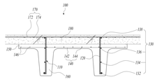
Figure 2 is a cross-sectional view showing the on-site casting using the multi-rib PC slab according to the first embodiment of the present invention.
3 is a cross-sectional view illustrating an on-site casting using a multi-rib PC slab according to a second embodiment of the present invention.
Figure 4 is a side view showing the shear wire mesh.
5 is a plan view showing that binding reinforcing bars are welded to both sides of the horizontal wire mesh.
6 is a plan view showing that the binding wire mesh is welded to both sides of the horizontal wire mesh.
Figure 7 is a cross-sectional view showing the installation of the field reinforcement wire mesh on the top of the shear wire mesh of the multi-rib PC slab according to the first embodiment of the present invention.
FIG. 8 is a cross-sectional view showing a modified example in which two shear wire meshes overlap one rib portion in FIG. 7 .
9 is a cross-sectional view showing the installation of the field reinforcement wire mesh on the top of the shear wire mesh of the multi-rib PC slab according to the second embodiment of the present invention.
FIG. 10 is a cross-sectional view showing a modified example in which two shear wire meshes overlap one rib portion in FIG. 9 .
11 is a perspective view showing a temporary pedestal used for manufacturing a multi-rib PC slab according to the first embodiment of the present invention.
12 to 17 are views showing the manufacturing and construction process of the multi-rib PC slab according to the first embodiment of the present invention.
18 to 23 are views showing the manufacturing and construction process of the multi-rib PC slab according to the second embodiment of the present invention.
본 발명은 다양한 변환을 가할 수 있고 여러 가지 실시예를 가질 수 있는 바, 특정 실시예를 예시하고 상세한 설명에 상세하게 설명하고자 한다. 그러나, 이는 본 발명을 특정한 실시 형태에 대해 한정하려는 것이 아니며, 본 발명의 사상 및 기술 범위에 포함되는 모든 변환, 균등물 내지 대체물을 포함하는 것으로 이해되어야 한다.Since the present invention can apply various transformations and can have various embodiments, specific embodiments are illustrated and described in detail in the detailed description. However, this is not intended to limit the present invention to specific embodiments, and should be understood to include all modifications, equivalents, and substitutes included in the spirit and scope of the present invention.
본 발명에서 사용한 용어는 단지 특정한 실시예를 설명하기 위해 사용된 것으로, 본 발명을 한정하려는 의도가 아니다. 단수의 표현은 문맥상 명백하게 다르게 뜻하지 않는 한, 복수의 표현을 포함한다. 본 발명에서, '포함하다' 또는 '가지다' 등의 용어는 명세서상에 기재된 특징, 숫자, 단계, 동작, 구성요소, 부품 또는 이들을 조합한 것이 존재함을 지정하려는 것이지, 하나 또는 그 이상의 다른 특징들이나 숫자, 단계, 동작, 구성요소, 부품 또는 이들을 조합한 것들의 존재 또는 부가 가능성을 미리 배제하지 않는 것으로 이해되어야 한다.The terms used in the present invention are only used to describe specific embodiments, and are not intended to limit the present invention. The singular expression includes the plural expression unless the context clearly dictates otherwise. In the present invention, terms such as 'comprising' or 'having' are intended to designate that the features, numbers, steps, operations, components, parts, or combinations thereof described in the specification exist, and one or more other features It should be understood that this does not preclude the existence or addition of numbers, steps, operations, components, parts, or combinations thereof.
이하, 첨부된 도면을 참조하여 본 발명의 바람직한 실시예들을 상세히 설명한다. 이 때, 첨부된 도면에서 동일한 구성 요소는 가능한 동일한 부호로 나타내고 있음에 유의한다. 또한, 본 발명의 요지를 흐리게 할 수 있는 공지 기능 및 구성에 대한 상세한 설명은 생략할 것이다. 마찬가지 이유로 첨부 도면에 있어서 일부 구성요소는 과장되거나 생략되거나 개략적으로 도시되었다.Hereinafter, preferred embodiments of the present invention will be described in detail with reference to the accompanying drawings. In this case, it should be noted that in the accompanying drawings, the same components are denoted by the same reference numerals as much as possible. In addition, detailed descriptions of well-known functions and configurations that may obscure the gist of the present invention will be omitted. For the same reason, some components are exaggerated, omitted, or schematically illustrated in the accompanying drawings.
도 2는 본 발명의 제1실시예에 따른 멀티리브 PC 슬래브를 이용하여 현장 타설 시공한 것을 나타내는 단면도이고, 도 3은 본 발명의 제2실시예에 따른 멀티리브 PC 슬래브를 이용하여 현장 타설 시공한 것을 나타내는 단면도이며, 도 4는 전단철망을 나타내는 측면도이고, 도 5는 수평철망의 양측에 결속철근이 용접된 것을 나타내는 평면도이다.Figure 2 is a cross-sectional view showing the on-site casting using the multi-rib PC slab according to the first embodiment of the present invention, Fig. 3 is the on-site casting construction using the multi-rib PC slab according to the second embodiment of the present invention It is a cross-sectional view showing one thing, FIG. 4 is a side view showing a shear wire mesh, and FIG. 5 is a plan view showing that binding reinforcing bars are welded to both sides of the horizontal wire mesh.
도 2의 제1실시예의 경우 위치고정근(136)이 수평철망(140)의 위에 결합되어 수평철망(140)에 지지되고, 도 3의 제2실시예의 경우 위치고정근(136)이 수평철망(140)의 아래에 결합되어 수평철망(140)을 지지한다.In the case of the first embodiment of FIG. 2 , the fixing
본 발명의 멀티리브 PC 슬래브(100)는, 평판 형태의 슬래브부(150), 슬래브부의 하면에 소정 간격으로 일체로 형성되는 복수의 리브부(160), 각 리브부의 내부에 매립되고 상단부가 슬래브부의 상면에서 돌출되도록 배치되는 복수의 전단철망(110), 및 슬래브부의 내부에 매립되고 복수의 전단철망에 결속되는 수평철망(140)을 포함한다.The
PC 슬래브(100)는 소정 두께를 가지고 평판 형태로 형성되는 슬래브부(150)의 하면에 2 이상의 리브부(160)가 일체로 형성될 수 있다. 도면에는 한 쌍의 리브부(160)가 형성된 것을 도시하였으나, 본 발명은 3개의 리브부를 가진 트라이티(tri-T) 슬래브 또는 4개 이상의 리브부를 가진 멀티리브(multi-rib) 슬래브에도 적용될 수 있다.In the
슬래브부(150)는 위에서 보면 직사각형 모양으로 형성될 수 있다. 리브부(160)는 길쭉한 직육면체에 가까운 형태로 형성될 수 있다. 리브부(160)가 슬래브부(150)에 연결되는 모서리 부위는 라운드지게 형성될 수 있다. 또한, 도 2 및 도 3에 도시된 바와 같이, 리브부(160)는 상부 폭이 하부 폭보다 크도록 양측면이 경사지게 형성되어, 그 단면이 사다리꼴 형태로 형성될 수 있다.The
PC 슬래브(100)의 내부에는 전단철망(110)과 수평철망(140)이 매립될 수 있다. 전단철망(110)은 리브부(160)의 폭방향 중심부에 배치되고 상단부가 슬래브부(150)의 상단에 노출될 수 있다. 수평철망(140)은 슬래브부(150) 내부에 모두 매립되고, 전단철망(110)과 수직으로 교차하도록 배치될 수 있다.The
전단철망(110)은 지면에 대해 수직으로 배치되는 복수의 전단철근(120)과, 복수의 전단철근의 일측에 용접되는 복수의 수평철근(130)을 포함할 수 있다.The
전단철망(110)은 소정 간격으로 배열되는 복수의 전단철근(120)과, 각 전단철근(120)의 일측면에 소정 높이로 배치되어 용접되는 복수의 수평철근(130)으로 구성될 수 있다. 전단철근(120)들과 수평철근(130)들은 자동 용접장치에 의해 자동으로 용접되어, 소정의 크기를 가진 직사각형 윤곽의 전단철망(110)으로 제작될 수 있다.The
도 4에 도시된 바와 같이, 수평철근(130)은 복수의 전단철근(120)의 하단 일측에 용접되는 하부정착근(132)과, 복수의 전단철근(120)의 상부 일측에 용접되어 수평철망(140)에 결합되는 위치고정근(136)과, 복수의 전단철근(120)의 상단 일측에 용접되어 현장배근철망(170)을 지지하는 상부정착근(138)을 포함할 수 있다.4, the horizontal reinforcing
하부정착근(132)은 복수의 전단철근(120)의 일측면 하단에 용접되어, 전단철망(110)을 PC 슬래브의 리브부(160)에 정착하고 주근의 보조 역할을 할 수 있다.The lower
위치고정근(136)은 복수의 전단철근(120)의 일측면 상부에 용접되어, 수평철망(140)에 결합될 수 있다. 도 2의 제1실시예에서 위치고정근(136)은 수평철망(140)의 위에 결합되어 수평철망(140)에 지지되고, 도 3의 제2실시예에서 위치고정근(136)은 수평철망(140)의 아래에 결합되어 수평철망(140)을 지지한다.The
수평철망(140)은 소정 간격으로 배열되는 복수의 가로철근(142)과, 복수의 가로철근의 상측면에 직교하도록 용접되는 복수의 세로철근(144)을 포함할 수 있다. 복수의 가로철근(142)과 복수의 세로철근(144)을 자동 용접하여 수평철망(140)을 미리 제작하여 사용할 수 있다.The
도 5에 도시된 바와 같이, 수평철망(140)에서 전단철망(110)의 외측에는 복수의 가로철근(142)에 복수의 결속철근(146)이 결합될 수 있다. 즉, 복수의 가로철근(142)에서 전단철망(110)이 배치되는 부위의 외측 양단부에는 세로철근(144)이 용접되지 않고, 전단철망(110)과 수평철망(140)을 결합한 다음에 복수의 결속철근(146)을 배치하여 결속할 수 있다. 미리 제작된 수평철망(140)에서 복수의 결속철근(146)은 복수의 가로철근(142)에 용접되는 것이 아니라 결속철선 등에 의해 결속되어 결합될 수 있다.As shown in FIG. 5 , a plurality of binding reinforcing
상부정착근(138)은 현장에서 현장배근철망(170)을 지지하기 위해 복수의 전단철근(120)의 일측면 상단에 용접될 수 있다.The upper
현장배근철망(170)도 소정 간격으로 배열되는 복수의 가로철근(172)과, 복수의 가로철근의 상측면에 직교하도록 용접되는 복수의 세로철근(174)을 포함할 수 있다. 복수의 가로철근(172)과 복수의 세로철근(174)을 자동 용접하여 현장배근철망(170)을 미리 제작하여 사용할 수 있다.The on-site
수평철근(130)은 리브부(160)가 높은 경우 복수의 전단철근(120)의 하부 일측에 용접되는 리브복부근(134)을 더 포함할 수 있다. 이 리브복부근(134)은 리브부(160)의 높이가 길게 형성될 경우, 리브부(160)의 강도를 보강할 수 있다.The horizontal reinforcing
위치고정근(136)과 리브복부근(134)은 전단철근(120)과 동일한 직경(D1)을 가지고, 상부정착근(138)은 전단철근(120)의 직경(D1)보다 큰 직경(D2)을 가지며, 하부정착근(132)은 상부정착근(138)의 직경(D2)보다 큰 직경(D3)을 가질 수 있다.The fixed
예를 들어, 전단철근(120)과 리브복부근(134)과 위치고정근(136)은 약 10mm의 직경(D1)을 갖도록 형성되고, 상부정착근(138)은 약 13mm의 직경(D2)을 갖도록 형성되며, 하부정착근(132)은 약 16mm의 직경(D3)을 갖도록 형성될 수 있다.For example, the
하부정착근(132)은 PC 슬래브의 리브부(160) 내부에 전단철망(110)을 정착하고 주근의 보조 역할을 하므로, 가장 두꺼운 철근으로 구성할 수 있다.The lower
상부정착근(138)은 PC 슬래브의 슬래브부(150) 상면으로 노출되고 현장배근철망(170)을 지지하므로 중간 정도의 직경을 가진 철근으로 구성할 수 있다.The upper
위치고정근(136)은 PC 슬래브의 슬래브부(150) 내부에 매립되는 수평철망(140)에 결합되고, 콘크리트가 타설되어 미리 제작되므로, 전단철근(120)과 동일한 정도의 작은 직경을 가진 철근으로 구성할 수 있다.The
한편, 도 6에 도시된 바와 같이, 복수의 결속철근은 복수의 세로철근과 복수의 가로철근이 용접된 결속철망(148)으로 구성될 수도 있다. 이 경우, 수평철망(140)의 양단부에서 수평철망(140)의 가로철근(142)들과 결속철망(148)의 가로철근들은 서로 겹치거나 접촉하거나 인접하게 결속될 수 있다.On the other hand, as shown in FIG. 6, the plurality of binding reinforcing bars may be composed of a
도 7은 본 발명의 제1실시예에 따른 멀티리브 PC 슬래브의 전단철망 상단에 현장배근철망을 설치한 것을 나타내는 단면도이고, 도 8은 도 7에서 하나의 리브부에 2개의 전단철망이 겹치도록 배치된 변형예를 나타내는 단면도이며, 도 9는 본 발명의 제2실시예에 따른 멀티리브 PC 슬래브의 전단철망 상단에 현장배근철망을 설치한 것을 나타내는 단면도이고, 도 10은 도 9에서 하나의 리브부에 2개의 전단철망이 겹치도록 배치된 변형예를 나타내는 단면도이다.7 is a cross-sectional view showing that the field reinforcement wire mesh is installed on the top of the shear wire mesh of the multi-rib PC slab according to the first embodiment of the present invention, and FIG. It is a cross-sectional view showing an arranged modified example, and FIG. 9 is a cross-sectional view showing that the field reinforcement wire mesh is installed on the top of the shear wire mesh of the multi-rib PC slab according to the second embodiment of the present invention, and FIG. 10 is a single rib in FIG. It is a cross-sectional view showing a modified example in which two shear wire meshes are arranged to overlap each other.
도 7에 도시된 바와 같이, 위치고정근(136)은 수평철망(140)의 상면에 지지되도록 결합될 수 있다. 제1실시예의 경우, 수평철망(140)을 먼저 설치하고 전단철망(110)을 안착시키므로, 위치고정근(136)은 수평철망(140)의 가로철근(144)의 상면에 지지될 수 있다.As shown in FIG. 7 , the
도 8에 도시된 바와 같이, 전단철망(110)은 각 리브부(160)에 2개씩 겹쳐서 배치될 수 있다. 겹치도록 배치되는 2개의 전단철망(110)은 전단철망이 하나만 있는 경우에 비해 그 강도가 우수하다.As shown in FIG. 8 , the
한편, 전단철망(110)은 측면에서 볼 때 길이방향 중간부에 도 7에서와 같은 전단철망(110)이 하나 배치되고, 전단철망(110)의 양단부에 도 8에서와 같은 겹쳐진 한 쌍의 전단철망(110)이 사용될 수 있다. 보통, 보의 양단부에서 중간부에 비해 2배 이상의 전단력을 견딜 수 있어야 하므로, 보의 양단부에 전단철망(110)을 하나 더 겹쳐서 설치할 수 있다. 즉, 전단철망(110)은 중간부에 하나가 배치되고 양단부에 2개가 겹치도록 배치됨으로써, 리브부(160)에 가해지는 전단력을 효율적으로 지지할 수 있다.On the other hand, the
도 9에 도시된 바와 같이, 위치고정근(136)은 수평철망(140)을 하면에서 지지하도록 결합될 수 있다. 제2실시예의 경우, 전단철망(110)을 먼저 설치하고 수평철망(140)을 안착시키므로, 위치고정근(136)은 수평철망(140)의 가로철근(144)의 하면을 지지할 수 있다.As shown in Figure 9, the
도 10에 도시된 바와 같이, 전단철망(110)은 각 리브부(160)에 2개씩 겹쳐서 배치될 수 있다. 겹치도록 배치되는 2개의 전단철망(110)은 전단철망이 하나만 있는 경우에 비해 그 강도가 우수하다.As shown in FIG. 10 , the
한편, 전단철망(110)은 측면에서 볼 때 길이방향 중간부에 도 9에서와 같은 전단철망(110)이 하나 배치되고, 전단철망(110)의 양단부에 도 10에서와 같은 겹쳐진 한 쌍의 전단철망(110)이 사용될 수 있다. 보통, 보의 양단부에서 중간부에 비해 2배 이상의 전단력을 견딜 수 있어야 하므로, 보의 양단부에 전단철망(110)을 하나 더 겹쳐서 설치할 수 있다. 즉, 전단철망(110)은 중간부에 하나가 배치되고 양단부에 2개가 겹치도록 배치됨으로써, 리브부(160)에 가해지는 전단력을 효율적으로 지지할 수 있다.On the other hand, the
도 11은 본 발명의 제1실시예에 따른 멀티리브 PC 슬래브의 제작에 사용되는 가설받침대를 나타내는 사시도이고, 도 12 내지 도 17은 본 발명의 제1실시예에 따른 멀티리브 PC 슬래브의 제작 및 시공 과정을 나타내는 도면이다.11 is a perspective view showing a temporary pedestal used for manufacturing the multi-rib PC slab according to the first embodiment of the present invention, and FIGS. 12 to 17 are the manufacturing and A drawing showing the construction process.
도 11 내지 도 17을 참조하여 본 발명의 제1실시예에 따른 멀티리브 PC 슬래브의 제작 및 이를 이용한 슬래브 시공 방법을 설명한다.The manufacturing of the multi-rib PC slab according to the first embodiment of the present invention and a slab construction method using the same will be described with reference to FIGS. 11 to 17 .
도 11에 도시된 가설받침대(200)는 수평철망(140)을 지면에서 소정 높이로 배치하기 위한 것이다. 직사각형의 수평철망(140)을 지지하기 위해서 가설받침대(200)는 소정 높이로 형성되고 양측 상단에 평판 형태의 지지대를 구비할 수 있다. 가설받침대(200)의 하면에서 지지대의 상면까지의 높이는 PC 슬래브의 형틀 바닥에서 수평철망(140)의 하면까지의 높이에 해당한다.The
먼저, 도 12에 도시된 바와 같이, 가설받침대(200)를 이용하여 수평철망(140)을 소정 높이로 배치한다. 이때, 수평철망(140)은 복수의 가로철근(142)과 복수의 세로철근(144)이 용접된 반제품으로서, 수평철망(140)의 양단부에는 세로철근(144)이 없다.First, as shown in FIG. 12 , the
다음에, 도 13에 도시된 바와 같이, 수평철망(140)의 양측에서 한 쌍의 전단철망(110)을 끼워서 수직으로 결속한다. 그러면, 전단철망(110)의 위치고정근(136)이 수평철망(140)의 가로철근(142)에 지지된다. 결속철선으로 수평철망(140)과 전단철망(110)의 접촉부 사이를 결속하여 움직이지 않도록 고정할 수 있다.Next, as shown in FIG. 13 , a pair of shear wire meshes 110 are sandwiched from both sides of the
다음에, 도 14에 도시된 바와 같이, 수평철망(140)의 양측 가장자리 부위에 복수의 결속철근(146)을 결합한다. 결속철근(146)은 수평철망(140)의 세로철근(144)과 동일한 직경을 가진 것이지만, 세로철근(144)처럼 미리 용접되어 있지 않고, 결속철사로 가로철근(142)에 결속하여 고정할 수 있다.Next, as shown in FIG. 14 , a plurality of binding reinforcing
다음에, 도 15에 도시된 바와 같이, 조립된 수평철망(140)과 전단철망(110)을 형틀에 설치하고 콘크리트를 타설하여 멀티리브 PC 슬래브(100)를 제작한다. 물론, 가설받침대(200)를 제외하고 조립된 수평철망(140)과 전단철망(110)을 형틀에 설치한다. 전단철망(110)의 상단부가 노출되는 높이까지 콘크리트를 타설하고 양생한 후, 형틀을 분리하면 도 15에 도시된 바와 같은 멀티리브 PC 슬래브(100)가 완성된다.Next, as shown in FIG. 15 , the assembled
다음에, 도 16에 도시된 바와 같이, 제작된 PC 슬래브(100)를 현장에 설치하고 전단철망(110)의 상단에 현장배근철망(170)을 설치한다. 이때, 현장배근철망(170)의 가로철근(172)이 전단철망(110)의 상부정착근(138)에 지지될 수 있다. 가로철근(172)과 상부정착근(138)은 결속철근에 의해 결속되어 고정될 수도 있다.Next, as shown in FIG. 16 , the manufactured
마지막으로, 도 17에 도시된 바와 같이, PC 슬래브(100)의 위에 있는 현장배근철망(170) 주위에 거푸집을 설치하고, PC 슬래브(100)의 상면에 콘크리트를 타설하고 양생한 다음 거푸집을 분리한다. 그러면, 본 발명에 따른 PC 슬래브(100)를 이용하여 현장에서 철근 콘크리트 슬래브를 시공하는 작업이 완료된다.Finally, as shown in FIG. 17, a formwork is installed around the field
도 18 내지 도 23은 본 발명의 제2실시예에 따른 멀티리브 PC 슬래브의 제작 및 시공 과정을 나타내는 도면이다.18 to 23 are views showing the manufacturing and construction process of the multi-rib PC slab according to the second embodiment of the present invention.
도 18 내지 도 23을 참조하여 본 발명의 제2실시예에 따른 멀티리브 PC 슬래브의 제작 및 이를 이용한 슬래브 시공 방법을 설명한다.A manufacturing method of a multi-rib PC slab according to a second embodiment of the present invention and a slab construction method using the same will be described with reference to FIGS. 18 to 23 .
먼저, 도 18에 도시된 바와 같이, 복수의 전단철망(110)을 지면에 수직으로 세워서 배치한다. 복수의 전단철망(110)을 지면에 수직으로 배치한 것을 유지하기 위해 복수의 지지대(미도시)를 사용할 수 있다. 이때, 복수의 전단철망(110)은 복수의 전단철근(120)과 복수의 수평철근(130)이 용접된 반제품으로서, 제작되는 리브부(160)의 높이가 작은 경우 리브복부근(134)이 없고, 리브부(160)의 높이가 큰 경우 리브복부근(134)도 함께 용접된 것을 사용한다.First, as shown in FIG. 18 , a plurality of shear wire meshes 110 are vertically placed on the ground. A plurality of supports (not shown) may be used to maintain the plurality of shear wire meshes 110 vertically arranged on the ground. At this time, the plurality of
다음에, 도 19에 도시된 바와 같이, 복수의 전단철망(110)에 수평철망(140)을 수직으로 끼워서 결속한다. 이때, 수평철망(140)은 복수의 가로철근(142)과 복수의 세로철근(144)이 용접된 반제품으로서, 수평철망(140)의 양단부에는 세로철근(144)이 없다. 그러면, 전단철망(110)의 위치고정근(136)에 수평철망(140)의 가로철근(142)이 지지된다. 결속철선으로 수평철망(140)과 전단철망(110)의 접촉부 사이를 결속하여 움직이지 않도록 고정할 수 있다.Next, as shown in FIG. 19 , the
다음에, 도 20에 도시된 바와 같이, 수평철망(140)의 양측 가장자리 부위에 복수의 결속철근(146)을 결합한다. 결속철근(146)은 수평철망(140)의 세로철근(144)과 동일한 직경을 가진 것이지만, 세로철근(144)처럼 미리 용접되어 있지 않고, 결속철사로 가로철근(142)에 결속하여 고정할 수 있다.Next, as shown in FIG. 20 , a plurality of binding reinforcing
다음에, 도 21에 도시된 바와 같이, 조립된 전단철망(110)과 수평철망(140)을 형틀에 설치하고 콘크리트를 타설하여 멀티리브 PC 슬래브(100)를 제작한다. 전단철망(110)의 상단부가 노출되는 높이까지 콘크리트를 타설하고 양생한 후, 형틀을 분리하면 도 21에 도시된 바와 같은 멀티리브 PC 슬래브(100)가 완성된다.Next, as shown in FIG. 21 , the assembled
다음에, 도 22에 도시된 바와 같이, 제작된 PC 슬래브(100)를 현장에 설치하고 전단철망(110)의 상단에 현장배근철망(170)을 설치한다. 이때, 현장배근철망(170)의 가로철근(172)이 전단철망(110)의 상부정착근(138)에 지지될 수 있다. 가로철근(172)과 상부정착근(138)은 결속철근에 의해 결속되어 고정될 수도 있다.Next, as shown in FIG. 22 , the manufactured
마지막으로, 도 23에 도시된 바와 같이, PC 슬래브(100)의 위에 있는 현장배근철망(170) 주위에 거푸집을 설치하고, PC 슬래브(100)의 상면에 콘크리트를 타설하고 양생한 다음 거푸집을 분리한다. 그러면, 본 발명에 따른 PC 슬래브(100)를 이용하여 현장에서 철근 콘크리트 슬래브를 시공하는 작업이 완료된다.Finally, as shown in FIG. 23, a formwork is installed around the on-site
이상, 본 발명의 일 실시예에 대하여 설명하였으나, 해당 기술 분야에서 통상의 지식을 가진 자라면 청구범위에 기재된 본 발명의 사상으로부터 벗어나지 않는 범위 내에서, 구성 요소의 부가, 변경, 삭제 또는 추가 등에 의해 본 발명을 다양하게 수정 및 변경할 수 있을 것이며, 이 또한 본 발명의 권리범위 내에 포함된다고 할 것이다.In the above, an embodiment of the present invention has been described, but those of ordinary skill in the art can add, change, delete, or add components within the scope that does not depart from the spirit of the present invention described in the claims. Various modifications and changes of the present invention will be possible by this, and this will also be included within the scope of the present invention.
10: 멀티리브 PC 슬래브(종래기술)
20: 주근 30: 수평철근
32: 가로철근 34: 세로철근
50: 후크철근
100: 멀티리브 PC 슬래브(본 발명)
110: 전단철망 120: 전단철근
130: 수평철근 132: 하부정착근
134: 리브복부근 136: 위치고정근
138: 상부정착근 140: 수평철망
142: 가로철근 144: 세로철근
146: 결속철근 148: 결속철망
150: 슬래브부 160: 리브부
170: 현장배근철망 172: 가로철근
174: 세로철근 180: 현장타설 콘크리트
200: 가설받침대10: Multi-rib PC slab (prior art)
20: main bar 30: horizontal reinforcing bar
32: horizontal reinforcing bar 34: vertical reinforcing bar
50: hook reinforcing bar
100: multi-rib PC slab (invention)
110: shear wire mesh 120: shear reinforcement
130: horizontal reinforcing bar 132: lower anchoring bar
134: rib abdominal muscle 136: position fixator muscle
138: upper anchor 140: horizontal wire mesh
142: horizontal reinforcing bar 144: vertical reinforcing bar
146: binding reinforcing bar 148: binding wire mesh
150: slab part 160: rib part
170: field reinforcement wire mesh 172: transverse reinforcement
174: vertical reinforcing bar 180: cast-in-place concrete
200: temporary support
Claims (19)
상기 슬래브부의 하면에 소정 간격으로 일체로 형성되는 복수의 리브부;
각 리브부의 내부에 매립되고 상단부가 상기 슬래브부의 상면에서 돌출되도록 배치되는 복수의 전단철망; 및
가로철근들과 세로철근들이 용접되어 미리 제작되고 상기 슬래브부의 내부에 매립되며 상기 복수의 전단철망에 결속되는 수평철망을 포함하고,
상기 수평철망에서 상기 전단철망의 외측에는 복수의 가로철근에 복수의 결속철근이 결합되며,
상기 전단철망은 수직으로 배치되는 복수의 전단철근과, 상기 복수의 전단철근의 일측에 용접되는 복수의 수평철근을 포함하며 미리 제작되고,
상기 수평철근은 상기 복수의 전단철근의 하단 일측에 용접되는 하부정착근과, 상기 리브부가 높은 경우 상기 복수의 전단철근의 하부 일측에 용접되는 리브복부근과, 상기 복수의 전단철근의 상부 일측에 용접되어 상기 수평철망에 결합되는 위치고정근과, 상기 복수의 전단철근의 상단 일측에 용접되어 가로철근들과 세로철근들이 용접되어 미리 제작된 현장배근철망을 지지하는 상부정착근을 포함하며,
상기 위치고정근은 상기 수평철망의 상면에 지지되도록 결합되거나, 상기 수평철망을 하면에서 지지하도록 결합되는 것을 특징으로 하는 용접철망을 구비하는 멀티리브 PC 슬래브.a slab portion in the form of a flat plate;
a plurality of ribs integrally formed on a lower surface of the slab at predetermined intervals;
a plurality of shear wire meshes embedded in each rib part and disposed so that the upper end protrudes from the upper surface of the slab part; and
Horizontal reinforcing bars and vertical reinforcing bars are pre-fabricated by welding, embedded in the interior of the slab, and include a horizontal wire mesh bound to the plurality of shear wire meshes,
A plurality of binding reinforcing bars are coupled to a plurality of transverse reinforcing bars on the outside of the shear wire mesh in the horizontal wire mesh,
The shear wire mesh includes a plurality of shear reinforcing bars disposed vertically, and a plurality of horizontal reinforcing bars welded to one side of the plurality of shear reinforcing bars, and is manufactured in advance,
The horizontal reinforcing bar includes a lower anchoring reinforcing bar welded to one side of the lower end of the plurality of shear reinforcing bars, a rib abdominal reinforcing bar welded to one lower side of the plurality of shear reinforcing bars when the rib portion is high, and welding to an upper side of the plurality of shear reinforcing bars It includes a position fixing reinforcing bar coupled to the horizontal wire mesh, and an upper anchoring reinforcing bar welded to one side of the upper end of the plurality of shear reinforcing bars to support the pre-fabricated on-site reinforcement wire mesh by welding horizontal reinforcing bars and vertical reinforcing bars,
The multi-rib PC slab having a welded wire mesh, characterized in that the position fixing muscle is coupled to be supported on the upper surface of the horizontal wire mesh or coupled to support the horizontal wire mesh from the lower surface.
상기 위치고정근과 상기 리브복부근은 상기 전단철근과 동일한 직경(D1)을 가지고,
상기 상부정착근은 상기 전단철근의 직경(D1)보다 큰 직경(D2)을 가지며,
상기 하부정착근은 상기 상부정착근의 직경(D2)보다 큰 직경(D3)을 가진 것을 특징으로 하는 용접철망을 구비하는 멀티리브 PC 슬래브.According to claim 1,
The position fixing muscle and the rib abdominal muscle have the same diameter (D1) as the shear reinforcement,
The upper anchoring muscle has a larger diameter (D2) than the diameter (D1) of the shear reinforcement,
The multi-rib PC slab having a welded wire mesh, characterized in that the lower anchorage has a larger diameter (D3) than the diameter (D2) of the upper anchorage.
상기 복수의 결속철근은 복수의 세로철근과 복수의 가로철근이 용접된 결속철망인 것을 특징으로 하는 용접철망을 구비하는 멀티리브 PC 슬래브.According to claim 1,
The plurality of binding reinforcing bars is a multi-rib PC slab having a welded wire mesh, characterized in that it is a binding wire mesh in which a plurality of vertical reinforcing bars and a plurality of horizontal reinforcing bars are welded.
상기 전단철망은 각 리브부에 2개씩 겹쳐서 배치되는 것을 특징으로 하는 용접철망을 구비하는 멀티리브 PC 슬래브.According to claim 1,
The shear wire mesh is a multi-rib PC slab having a welded wire mesh, characterized in that the two overlapping each rib portion.
상기 수평철망의 양측에서 전단철근들과 수평철근들이 용접되어 미리 제작된 전단철망을 끼워서 수직으로 결속하는 단계;
상기 수평철망의 양측 가장자리 부위에 복수의 결속철근을 결합하는 단계;
조립된 수평철망과 전단철망을 형틀에 설치하고 콘크리트를 타설하여 멀티리브 PC 슬래브를 제작하는 단계;
상기 전단철망의 상단에 현장배근철망을 설치하는 단계; 및
상기 PC 슬래브의 상면에 콘크리트를 타설하고 양생하는 단계를 포함하고,
상기 전단철망은 수직으로 배치되는 복수의 전단철근과, 상기 복수의 전단철근의 일측에 용접되는 복수의 수평철근을 포함하며,
상기 수평철근은 상기 복수의 전단철근의 하단 일측에 용접되는 하부정착근과, 상기 복수의 전단철근의 하부 일측에 용접되는 리브복부근과, 상기 복수의 전단철근의 상부 일측에 용접되어 상기 수평철망에 결합되는 위치고정근과, 상기 복수의 전단철근의 상단 일측에 용접되어 가로철근들과 세로철근들이 용접되어 미리 제작된 현장배근철망을 지지하는 상부정착근을 포함하고,
상기 전단철망의 위치고정근은 상기 수평철망에 안착되어 지지되는 것을 특징으로 하는 용접철망을 구비하는 멀티리브 PC 슬래브의 제작 및 시공 방법.arranging a horizontal wire mesh prepared in advance by welding horizontal reinforcing bars and vertical reinforcing bars using a temporary pedestal to a predetermined height;
The shear reinforcement and the horizontal reinforcement are welded on both sides of the horizontal wire mesh, vertically binding the shear wire mesh by inserting a pre-fabricated wire mesh;
coupling a plurality of binding reinforcing bars to both edge portions of the horizontal wire mesh;
manufacturing a multi-rib PC slab by installing the assembled horizontal wire mesh and shear wire mesh on the formwork and pouring concrete;
Installing a field reinforcement wire mesh on top of the shear wire mesh; and
Containing the step of pouring and curing the concrete on the upper surface of the PC slab,
The shear wire mesh includes a plurality of shear reinforcing bars disposed vertically, and a plurality of horizontal reinforcing bars welded to one side of the plurality of shear reinforcing bars,
The horizontal reinforcing bar includes a lower anchoring reinforcing bar welded to one lower end of the plurality of shear reinforcing bars, a rib abdominal reinforcing bar welded to one lower side of the plurality of shear reinforcing bars, and welding to an upper side of the plurality of shear reinforcing bars to the horizontal wire mesh It includes a position fixing reinforcing bar to be combined, and an upper anchoring reinforcing bar that is welded to one side of the upper end of the plurality of shear reinforcing bars and supports a pre-fabricated on-site reinforcement wire mesh by welding horizontal reinforcing bars and vertical reinforcing bars,
The method of manufacturing and constructing a multi-rib PC slab having a welded wire mesh, characterized in that the position fixing reinforcing the shear wire mesh is supported by being seated on the horizontal wire mesh.
상기 위치고정근은 상기 전단철근과 동일한 직경(D1)을 가지고,
상기 상부정착근은 상기 전단철근의 직경(D1)보다 큰 직경(D2)을 가지며,
상기 하부정착근은 상기 상부정착근의 직경(D2)보다 큰 직경(D3)을 가진 것을 특징으로 하는 용접철망을 구비하는 멀티리브 PC 슬래브의 제작 및 시공 방법.11. The method of claim 10,
The position fixing muscle has the same diameter (D1) as the shear reinforcement,
The upper anchoring muscle has a larger diameter (D2) than the diameter (D1) of the shear reinforcement,
The method of manufacturing and constructing a multi-rib PC slab having a welded wire mesh, characterized in that the lower anchorage has a larger diameter (D3) than the diameter (D2) of the upper anchorage.
상기 복수의 전단철망에 가로철근들과 세로철근들이 용접되어 미리 제작된 수평철망을 수직으로 끼워서 결속하는 단계;
상기 수평철망의 양측 가장자리 부위에 복수의 결속철근을 결합하는 단계;
조립된 전단철망과 수평철망을 형틀에 설치하고 콘크리트를 타설하여 멀티리브 PC 슬래브를 제작하는 단계;
상기 전단철망의 상단에 가로철근들과 세로철근들이 용접되어 미리 제작된 현장배근철망을 설치하는 단계; 및
상기 PC 슬래브의 상면에 현장타설 콘크리트를 타설하고 양생하는 단계를 포함하고,
상기 전단철망은 수직으로 배치되는 복수의 전단철근과, 상기 복수의 전단철근의 일측에 용접되는 복수의 수평철근을 포함하며,
상기 수평철근은 상기 복수의 전단철근의 하단 일측에 용접되는 하부정착근과, 상기 복수의 전단철근의 하부 일측에 용접되는 리브복부근과, 상기 복수의 전단철근의 상부 일측에 용접되어 상기 수평철망에 결합되는 위치고정근과, 상기 복수의 전단철근의 상단 일측에 용접되어 현장배근철망을 지지하는 상부정착근을 포함하고,
상기 수평철망은 상기 전단철망의 위치고정근에 안착되어 지지되는 것을 특징으로 하는 용접철망을 구비하는 멀티리브 PC 슬래브의 제작 및 시공 방법.A step of arranging a plurality of shear reinforcing bars and horizontal reinforcing bars are welded in advance by standing vertically on the ground;
connecting horizontal reinforcing bars and vertical reinforcing bars to the plurality of shear wire meshes by vertically inserting a pre-fabricated horizontal wire mesh;
coupling a plurality of binding reinforcing bars to both edge portions of the horizontal wire mesh;
manufacturing a multi-rib PC slab by installing the assembled shear wire mesh and horizontal wire mesh on the formwork and pouring concrete;
Installing a pre-fabricated on-site reinforcement wire mesh by welding horizontal reinforcing bars and vertical reinforcing bars on the upper end of the shear wire mesh; and
Including the step of pouring and curing cast-in-place concrete on the upper surface of the PC slab,
The shear wire mesh includes a plurality of shear reinforcing bars disposed vertically, and a plurality of horizontal reinforcing bars welded to one side of the plurality of shear reinforcing bars,
The horizontal reinforcing bar includes a lower anchoring reinforcing bar welded to one lower end of the plurality of shear reinforcing bars, a rib abdominal reinforcing bar welded to one lower side of the plurality of shear reinforcing bars, and welding to an upper side of the plurality of shear reinforcing bars to the horizontal wire mesh It includes a fixed position fixed reinforcing bar to be coupled, and an upper anchoring reinforcing bar that is welded to one side of the upper end of the plurality of shear reinforcing bars to support the field reinforcement wire mesh,
The horizontal wire mesh is a method of manufacturing and constructing a multi-rib PC slab having a welded wire mesh, characterized in that it is supported by being seated on a position fixing root of the shear wire mesh.
상기 위치고정근은 상기 전단철근과 동일한 직경(D1)을 가지고,
상기 상부정착근은 상기 전단철근의 직경(D1)보다 큰 직경(D2)을 가지며,
상기 하부정착근은 상기 상부정착근의 직경(D2)보다 큰 직경(D3)을 가진 것을 특징으로 하는 용접철망을 구비하는 멀티리브 PC 슬래브의 제작 및 시공 방법.16. The method of claim 15,
The position fixing muscle has the same diameter (D1) as the shear reinforcement,
The upper anchoring muscle has a larger diameter (D2) than the diameter (D1) of the shear reinforcement,
The method of manufacturing and constructing a multi-rib PC slab having a welded wire mesh, characterized in that the lower anchorage has a larger diameter (D3) than the diameter (D2) of the upper anchorage.
Priority Applications (1)
| Application Number | Priority Date | Filing Date | Title |
|---|---|---|---|
| KR1020200156757A KR102354464B1 (en) | 2020-11-20 | 2020-11-20 | Multi-rib PC slab having welded wire mesh and method for manufacturing and construction of the multi-rib PC slab |
Applications Claiming Priority (1)
| Application Number | Priority Date | Filing Date | Title |
|---|---|---|---|
| KR1020200156757A KR102354464B1 (en) | 2020-11-20 | 2020-11-20 | Multi-rib PC slab having welded wire mesh and method for manufacturing and construction of the multi-rib PC slab |
Publications (1)
| Publication Number | Publication Date |
|---|---|
| KR102354464B1 true KR102354464B1 (en) | 2022-01-21 |
Family
ID=80050439
Family Applications (1)
| Application Number | Title | Priority Date | Filing Date |
|---|---|---|---|
| KR1020200156757A KR102354464B1 (en) | 2020-11-20 | 2020-11-20 | Multi-rib PC slab having welded wire mesh and method for manufacturing and construction of the multi-rib PC slab |
Country Status (1)
| Country | Link |
|---|---|
| KR (1) | KR102354464B1 (en) |
Citations (6)
| Publication number | Priority date | Publication date | Assignee | Title |
|---|---|---|---|---|
| JP2000038797A (en) * | 1998-07-22 | 2000-02-08 | Ishikawajima Constr Materials Co Ltd | Semi-precast floor slab |
| KR101086222B1 (en) * | 2009-05-11 | 2011-11-24 | 동서 피, 씨, 씨 주식회사 | PC slave for building having reinforcement structure as a set |
| KR101220678B1 (en) | 2012-05-02 | 2013-01-10 | 서울시립대학교 산학협력단 | Rib optimized slab |
| KR20160124035A (en) * | 2015-04-17 | 2016-10-26 | (주)연우피씨엔지니어링 | Shear-reinforcement half pc slab structure and construction method |
| JP2019189998A (en) * | 2018-04-18 | 2019-10-31 | 日本製鉄株式会社 | Concrete floor structure and structure |
| KR102056647B1 (en) * | 2019-07-19 | 2019-12-17 | (주)지산개발 | Pc floor plate for insulated logistics warehouse and method of making it |
-
2020
- 2020-11-20 KR KR1020200156757A patent/KR102354464B1/en active IP Right Grant
Patent Citations (6)
| Publication number | Priority date | Publication date | Assignee | Title |
|---|---|---|---|---|
| JP2000038797A (en) * | 1998-07-22 | 2000-02-08 | Ishikawajima Constr Materials Co Ltd | Semi-precast floor slab |
| KR101086222B1 (en) * | 2009-05-11 | 2011-11-24 | 동서 피, 씨, 씨 주식회사 | PC slave for building having reinforcement structure as a set |
| KR101220678B1 (en) | 2012-05-02 | 2013-01-10 | 서울시립대학교 산학협력단 | Rib optimized slab |
| KR20160124035A (en) * | 2015-04-17 | 2016-10-26 | (주)연우피씨엔지니어링 | Shear-reinforcement half pc slab structure and construction method |
| JP2019189998A (en) * | 2018-04-18 | 2019-10-31 | 日本製鉄株式会社 | Concrete floor structure and structure |
| KR102056647B1 (en) * | 2019-07-19 | 2019-12-17 | (주)지산개발 | Pc floor plate for insulated logistics warehouse and method of making it |
Similar Documents
| Publication | Publication Date | Title |
|---|---|---|
| KR101125673B1 (en) | Structure of a precast diaphragm for making a prestressed concrete girder and method making the girder thereof | |
| KR101440434B1 (en) | Construction Method for Composite Type Rahmen Bridge | |
| KR101570484B1 (en) | Half-PC Column using lightweight Encased Inner Form And Manufacturing Method Thereof, And Construction Method Using The Same | |
| KR101285487B1 (en) | none module correspondence and horizontal shear performance enhanced hollow core slab and construction method using the same | |
| US10106973B1 (en) | Precast concrete building elements and assemblies thereof, and related methods | |
| KR101663132B1 (en) | Self-supporting type column structure | |
| KR101862278B1 (en) | Steel composite concrete member | |
| JP5703159B2 (en) | Precast prestressed concrete beam | |
| KR101117497B1 (en) | Bridge having continuous arch hybrid girders and the bridge construction method using the same | |
| JP6960082B2 (en) | How to build a skeleton by spraying concrete | |
| KR20010005431A (en) | Steel concrete structure | |
| KR102354464B1 (en) | Multi-rib PC slab having welded wire mesh and method for manufacturing and construction of the multi-rib PC slab | |
| KR101105883B1 (en) | Basic mat constructing method of high rise concrete structure | |
| KR101028372B1 (en) | Construction for connection of the truss assembled deck plates | |
| KR102409371B1 (en) | Rib-type PC slab having welded wire mesh with upper end hook and method for manufacturing and construction of the rib-type PC slab | |
| KR20170108215A (en) | I section steel half precast slab and manufacturing method and construction method of the same | |
| KR101527752B1 (en) | Construction method of prestressed composite girder bridge | |
| KR101181160B1 (en) | Prestressed precast concrete beam having efficient prestressing anchorage structure | |
| KR20110088563A (en) | Prestressed slab element | |
| KR102235873B1 (en) | Fabrication method of partial pier cap, partial pier cap, and construction method of pier using partial pier cap | |
| KR101846245B1 (en) | Helical lattice | |
| KR20160078150A (en) | Segmental prestressed concrete girder and method for constructing same | |
| JP7430092B2 (en) | Reinforcement bars, seismic isolation upper foundation structure and footing structure | |
| JPH10110498A (en) | Half-precast floor slab and construction method of hollow flat slab making use thereof | |
| JP7149772B2 (en) | Seismic isolation upper foundation structure and footing structure |
Legal Events
| Date | Code | Title | Description |
|---|---|---|---|
| GRNT | Written decision to grant |