KR20170108215A - I section steel half precast slab and manufacturing method and construction method of the same - Google Patents
I section steel half precast slab and manufacturing method and construction method of the same Download PDFInfo
- Publication number
- KR20170108215A KR20170108215A KR1020160031727A KR20160031727A KR20170108215A KR 20170108215 A KR20170108215 A KR 20170108215A KR 1020160031727 A KR1020160031727 A KR 1020160031727A KR 20160031727 A KR20160031727 A KR 20160031727A KR 20170108215 A KR20170108215 A KR 20170108215A
- Authority
- KR
- South Korea
- Prior art keywords
- plate
- base plate
- steel
- concrete
- steel beams
- Prior art date
Links
Images


Classifications
-
- E—FIXED CONSTRUCTIONS
- E04—BUILDING
- E04B—GENERAL BUILDING CONSTRUCTIONS; WALLS, e.g. PARTITIONS; ROOFS; FLOORS; CEILINGS; INSULATION OR OTHER PROTECTION OF BUILDINGS
- E04B5/00—Floors; Floor construction with regard to insulation; Connections specially adapted therefor
- E04B5/16—Load-carrying floor structures wholly or partly cast or similarly formed in situ
- E04B5/17—Floor structures partly formed in situ
- E04B5/18—Floor structures partly formed in situ with stiffening ribs or other beam-like formations wholly cast between filling members
-
- E—FIXED CONSTRUCTIONS
- E04—BUILDING
- E04B—GENERAL BUILDING CONSTRUCTIONS; WALLS, e.g. PARTITIONS; ROOFS; FLOORS; CEILINGS; INSULATION OR OTHER PROTECTION OF BUILDINGS
- E04B5/00—Floors; Floor construction with regard to insulation; Connections specially adapted therefor
- E04B5/16—Load-carrying floor structures wholly or partly cast or similarly formed in situ
- E04B5/17—Floor structures partly formed in situ
- E04B5/23—Floor structures partly formed in situ with stiffening ribs or other beam-like formations wholly or partly prefabricated
- E04B5/26—Floor structures partly formed in situ with stiffening ribs or other beam-like formations wholly or partly prefabricated with filling members between the beams
-
- E—FIXED CONSTRUCTIONS
- E04—BUILDING
- E04C—STRUCTURAL ELEMENTS; BUILDING MATERIALS
- E04C5/00—Reinforcing elements, e.g. for concrete; Auxiliary elements therefor
- E04C5/01—Reinforcing elements of metal, e.g. with non-structural coatings
- E04C5/06—Reinforcing elements of metal, e.g. with non-structural coatings of high bending resistance, i.e. of essentially three-dimensional extent, e.g. lattice girders
Abstract
The present invention can increase the length without increasing the thickness of the concrete by increasing the bending strength and the shear resistance. Therefore, it is possible to construct an economical construction suitable for the long span, A bottom plate, a method of manufacturing the same, and a construction method thereof.
According to another aspect of the present invention, there is provided an eyepiece half plate bottom plate comprising: a precast base plate placed in concrete at a predetermined height from a bottom; A lower reinforcing bar embedded in the precast base plate; Sectional structure of the pre-cast base plate. The pre-cast base plate is arranged on the pre-cast base plate in a wide and narrow space with a narrow interval so that the lower end thereof is buried in the concrete at a certain depth from the upper surface of the precast base plate, A plurality of steel beams; A plurality of reinforcing ribs formed by piling concrete higher than the precast base plate so that a predetermined amount including the upper flange is exposed between steel beams adjacent to each other at narrow intervals except for both sides of the plurality of steel beams .

Description
[0001] The present invention relates to a bottom plate of an eye shape steel half plate to be installed in a floor slab of a building, and a method of manufacturing the same. In particular, since the bending strength and the shear resistance are increased to increase the length without increasing the thickness of the concrete, And a method of manufacturing the same and a construction method thereof.
Half Precast Concrete Slab is a type of synthetic floor slab developed for the purpose of shortening the construction time and improving the workability by compromising and complementing the merits of the full PC construction method and the advantages of the field installation method. The bottom plate of a halfpix is made by putting a thin metal plate on a supporting member (beam, wall, etc.), placing the upper reinforcing steel on it, and then filling the remaining section of the topping concrete with the casting concrete. Which improves the structural performance and workability.
Truss root reinforcement type, hollow type and double tee type are known as half PC's bottom plate. Here, the hollow type half PC bottom plate refers to a prestressed concrete flat half PC bottom plate having a continuous cavity in its cross section, and it can be used up to a span of about 10 m since a prestress is introduced. The double tee type half plate bottom plate is the same as the one with the ribs attached to the lower surface of the flat plate and its shape is like two T-shaped ribs. Since the cross-sectional performance is improved by bending the plate to the deck plate shape, Is increased.
However, there is a problem in application to a high-rise building because a hollow half-pc floor is increased in thickness due to an increase in thickness, and the double-tee half PC bottom plate is projected on the bottom surface of the rebar, There is a problem in that it is limited.
Therefore, it is necessary to construct a half PC board so as not to increase the floor height, and a half PC board is required which is not limited to the plane configuration.
As a background of the present invention, Korean Registered Patent Registration No. 10-1225662 has proposed a prefabricated precast lattice type steel composite bottom plate and a construction method thereof. In the background art, the main beam is spaced apart from each other; A top bar in the form of a lattice, the top bar being formed in a vertical bar crossing a horizontal bar and a horizontal bar intersecting at right angles with the main beam at an upper portion of the main beam; A shear reinforcement steel plate provided on the joint portion spaced apart from the main beam and the upper bar so as to have a height from a bottom surface of the main beam and a top surface of the precast steel composite bottom plate; Shaped upper bar is formed on the lower surface of the upper concrete.
However, while the above-mentioned background art has a superior bending stiffness and strength of the steel composite bottom plate, it is necessary to construct a steel plate for shear key reinforcement for connecting the steel composite bottom plates to each other, The assembling process of the connecting member is required.
The present invention can increase the length without increasing the thickness of the concrete by increasing the bending strength and the shear resistance. Therefore, it is possible to construct an economical construction suitable for the long span, A bottom plate, a method of manufacturing the same, and a construction method thereof.
According to another aspect of the present invention, there is provided an eyepiece half plate bottom plate comprising: a precast base plate placed in concrete at a predetermined height from a bottom; A lower reinforcing bar embedded in the precast base plate; Sectional structure of the pre-cast base plate. The pre-cast base plate is arranged on the precast base plate in a wide and narrowly spaced-apart arrangement in a repeated manner so that the lower end thereof is embedded in the concrete at a certain depth from the upper surface of the precast base plate, A plurality of steel beams; A plurality of reinforcing ribs formed by piling concrete higher than the precast base plate so that a predetermined amount including the upper flange is exposed between steel beams adjacent to each other at narrow intervals except for both sides of the plurality of steel beams .
Further, a connecting brace is joined to the upper part of the steel beam beams opposed to each other at relatively wide intervals, and a reinforcing bar is pre-assembled at a predetermined interval thereunder.
It is also characterized in that between the steel beam beams opposed to each other at a relatively wide interval, the connecting support roots are joined to the upper portion, and the X-type reinforcing rods joined to both sides of the steel beam to the lower side of the steel beam are pre- assembled .
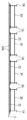
The connecting brace may be formed by folding the wire into a zigzag shape in a predetermined pattern and having a certain length of abdominal joint sections contacting the abdomen at regular intervals.
Meanwhile, a method of manufacturing an eyelet steel half plate according to a preferred embodiment of the present invention includes the steps of: (a) assembling a lower reinforcing bar to a form deck; (b) arranging a plurality of steel beams made of a steel material having an I-sectional structure upwardly of the lower reinforcing steel bar in a row at a predetermined position in the width direction and arranging them in a row and arranging them at a narrow interval; (c) placing the primary concrete at a predetermined height from the bottom plate of the formwork so that the lower ends of the plurality of steel beams are buried in the concrete at a predetermined depth, thereby manufacturing a precast base plate; (d) A secondary concrete is placed higher than the precast base plate by a certain amount higher than the precast base plate so that a predetermined amount including the upper flange is exposed between the steel beams adjacent to each other at a narrow gap except for both sides of the plurality of steel beams, And forming the reinforcing ribs.
In the step (b), the connecting beams may be joined to the upper part of the steel beams opposed to each other at relatively wide intervals, and the reinforcing bars may be pre-assembled at regular intervals thereunder.
According to another aspect of the present invention, there is provided a method of constructing an eyelet steel half plate, comprising the steps of supporting an eyelet steel half plate to a beam or a wall of a building; Placing a plate-like core on an upper surface of the connecting brace of the bottom plate of the eye section of the eye piece; Disposing a slab connection reinforcing bar in a slab reinforcement chamber of a longitudinally-extending eye-shaped steel half-pcard bottom plate; Placing an upper reinforcing bar on an upper portion of the eye profile steel half plate; And a second topping concrete is laid on the upper portion of the bottom plate of the I-shape steel half PC so that the upper reinforcing bars are embedded.
According to the eyepiece half plate bottom plate of the present invention and the construction method using the same, the steel beam and the concrete rib protruding from the base of the bottom plate are combined to increase the bending proof strength and shear resistance.
In addition, a plate-like core is installed at the time of construction to reduce the amount of the topping concrete being poured, thus making it possible to construct an economical slab.
Further, since the thickness of the slab can be reduced by increasing the bending proof strength of the half-plate bottom plate of the eye section, it is possible to prevent the height of the slab from becoming high, and the bottom surface of the precast base plate is flat, do.
BRIEF DESCRIPTION OF THE DRAWINGS The accompanying drawings, which are incorporated in and constitute a part of the specification, illustrate exemplary embodiments of the invention and, together with the description, serve to explain the principles of the invention, Shall not be construed as limiting.
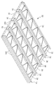
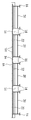
BRIEF DESCRIPTION OF THE DRAWINGS FIG. 1 is a perspective view of an eye section steel half plate according to the present invention; FIG.
Figure 2 is a front view of Figure 1;
3 is a perspective view of a multiple steel beam applied to the present invention.
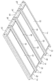
FIG. 4A is a perspective view of a set assembly in which two steel beams are joined together by a connecting brace and a reinforcing bar in the present invention. FIG.
Figure 4b is a modified perspective view of the one set assembly shown in Figure 4a.
5 is a perspective view of a connecting brace according to the present invention.
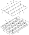
FIG. 6A is a perspective view showing a state before a plate-shaped core is installed on a bottom plate of an eye shape steel half plate according to the present invention. FIG.
FIG. 6B is a perspective view of the eye-shaped steel half plate according to the present invention, in which the plate-like core is installed. FIG.
7A to 7C are views showing a production process according to a manufacturing sequence of an eyepiece half plate according to the present invention;
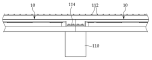
FIGS. 8A to 8C are views showing the construction of each of the eyepiece half plates according to the present invention. FIG.
DETAILED DESCRIPTION OF THE PREFERRED EMBODIMENTS The present invention will be described in detail below with reference to the embodiments shown in the accompanying drawings, but the present invention is not limited thereto.
As shown in Figs. 1 and 2, the eyepiece half
The
The
As shown in Fig. 3, the
A plurality of
The plurality of reinforcing
Accordingly, the
4A, the reinforcing
At this time, the connecting
4B, a connecting
A manufacturing method of the eyepiece half
First, a lower reinforcing
Then, a plurality of
Among the plurality of
Next, as shown in FIG. 7B, the primary concrete is laid at a predetermined height from the
Next, as shown in FIG. 7C, a predetermined amount of the
The
A construction method of the eyepiece half
First, as shown in FIG. 8A, the
Next, the plate-
Then, as shown in FIG. 8B, the slab connecting reinforcing
The
Next, as shown in FIG. 8C, the upper reinforcing
Next, a
According to the construction method using the I-beam half
In addition, by installing the plate-
Further, the thickness can be reduced by increasing the bending proof strength of the eyelet-type half
While the present invention has been particularly shown and described with reference to exemplary embodiments thereof, it is evident that many alternatives, modifications and variations will be apparent to those skilled in the art in light of the above teachings. will be. The invention is not limited by these variations and modifications, but is limited only by the claims appended hereto.
14: Steel beam
16: reinforcing rib
18: Precast base plate
181:
20: Connection support
22: sheet material core
Claims (7)
A lower reinforcing bar 181 embedded in the precast base plate 18;
Sectional structure of the precast base plate 18 and is arranged on the precast base plate 18 so as to be spaced apart from one another in a width direction and repeatedly and narrowly spaced so that the lower end thereof is buried in the concrete at a predetermined depth from the upper surface of the precast base plate 18 A plurality of steel beams 14 lying above the lower reinforcing bars 181;
The steel beam 14 and the steel beams 14 adjacent to each other at a narrow interval except for both sides of the plurality of steel beams 14 are relatively higher than the precast base plate 18 so that a certain amount including the upper flange is exposed. And a plurality of reinforcing ribs (16) formed by being poured into concrete.
And a reinforcing bar (15) is preliminarily assembled in the lower part at a lower part between the steel beams (14 and 14) opposed to each other at relatively wide intervals, Half Piece Floor Plate.
A connecting support rope 20 is joined to the upper portion between the steel beams 14 and 14 opposed to each other at a relatively wide interval and the lower support rope 20 is provided between the steel beams 14 and 14 And an X-shaped reinforcing bars (27, 27) joined to both ends are pre-assembled.
Wherein the connection supporting rope (20) has a plurality of abdomen joining sections of a predetermined length tangent to the abdomen part at regular intervals, by bending the wire members in a zigzag shape for a predetermined number of times.
(b) arranging a plurality of steel beams (14) made of a steel material having an I-sectional structure upwardly of the lower reinforcing bars (181) by arranging and arranging the steel beams (18) in a wide and narrow space at regular intervals in a width direction;
(c) placing the primary concrete at a predetermined height from the bottom plate of the formwork so that the lower ends of the plurality of steel beams 14 are buried in the concrete at a predetermined depth to manufacture the precast base plate 18;
(d) relative to the precast base plate 18 so as to expose a certain amount of the steel beam 14 including the upper flange between the steel beams 14 and 14 which are adjacent to each other at narrow intervals except for both sides, And forming a plurality of reinforcing ribs (16) by placing a second concrete at a higher level than the reinforcing ribs (16).
And the reinforcing bars 15 are preliminarily assembled to the lower portion between the steel beams 14 and 14 which are opposed to each other at relatively wide intervals, A method for manufacturing a bottom plate of an I-shape steel half PC.
Placing a plate-like core (22) on an upper surface of a connecting brace (20) of the eye plate half plate (10);
Disposing a slab connecting reinforcing bar (114) in the slab reinforcement chambers (23 and 23) of the longitudinally continuous eye-shaped steel half plates (10 and 10);
Placing an upper reinforcing bar (112) on an upper portion of the eye profile steel half plate (10);
Wherein the second topping concrete (116) is placed in the upper portion of the lower half plate (10) of the eye section so that the upper section (112) is embedded.
Priority Applications (1)
| Application Number | Priority Date | Filing Date | Title |
|---|---|---|---|
| KR1020160031727A KR20170108215A (en) | 2016-03-16 | 2016-03-16 | I section steel half precast slab and manufacturing method and construction method of the same |
Applications Claiming Priority (1)
| Application Number | Priority Date | Filing Date | Title |
|---|---|---|---|
| KR1020160031727A KR20170108215A (en) | 2016-03-16 | 2016-03-16 | I section steel half precast slab and manufacturing method and construction method of the same |
Publications (1)
| Publication Number | Publication Date |
|---|---|
| KR20170108215A true KR20170108215A (en) | 2017-09-27 |
Family
ID=60035950
Family Applications (1)
| Application Number | Title | Priority Date | Filing Date |
|---|---|---|---|
| KR1020160031727A KR20170108215A (en) | 2016-03-16 | 2016-03-16 | I section steel half precast slab and manufacturing method and construction method of the same |
Country Status (1)
| Country | Link |
|---|---|
| KR (1) | KR20170108215A (en) |
Cited By (3)
| Publication number | Priority date | Publication date | Assignee | Title |
|---|---|---|---|---|
| CN114457948A (en) * | 2020-11-10 | 2022-05-10 | 内蒙古中朵远大建筑工业有限公司 | Splicing seam structure of prefabricated bottom plate of bidirectional laminated slab and construction method of splicing seam structure |
| KR102397000B1 (en) * | 2022-02-03 | 2022-05-16 | 김건우 | Reinforced pc shear wall |
| CN116044055A (en) * | 2023-03-09 | 2023-05-02 | 湖南嘉晟住建科技有限公司 | Steel-concrete shear wall and pouring method thereof |
-
2016
- 2016-03-16 KR KR1020160031727A patent/KR20170108215A/en active IP Right Grant
Cited By (3)
| Publication number | Priority date | Publication date | Assignee | Title |
|---|---|---|---|---|
| CN114457948A (en) * | 2020-11-10 | 2022-05-10 | 内蒙古中朵远大建筑工业有限公司 | Splicing seam structure of prefabricated bottom plate of bidirectional laminated slab and construction method of splicing seam structure |
| KR102397000B1 (en) * | 2022-02-03 | 2022-05-16 | 김건우 | Reinforced pc shear wall |
| CN116044055A (en) * | 2023-03-09 | 2023-05-02 | 湖南嘉晟住建科技有限公司 | Steel-concrete shear wall and pouring method thereof |
Similar Documents
| Publication | Publication Date | Title |
|---|---|---|
| KR20060052720A (en) | Constructing the large-span self-braced building of composite load-bearing wall-panels and floors | |
| KR20120011043A (en) | Half precast floor plank, and slab construction method using same | |
| EA025335B1 (en) | Assemblable disposable shuttering for constructing modular formworks for making concrete foundations | |
| KR20170108215A (en) | I section steel half precast slab and manufacturing method and construction method of the same | |
| JP6253058B2 (en) | Reinforcing bar member and reinforced concrete structure using the reinforcing bar member | |
| JP2010275739A (en) | Reinforced structure and reinforced construction method | |
| JP6960082B2 (en) | How to build a skeleton by spraying concrete | |
| KR101286112B1 (en) | Composite girder with steel pipe and rahmen bridge construction method using the same | |
| CN111910811A (en) | Rib plate skeleton concrete cast-in-place board | |
| KR101028372B1 (en) | Construction for connection of the truss assembled deck plates | |
| KR101994089B1 (en) | Precast Concrete Slab With Pullout-Shear Resistance Elements Of Mesh Rib And Manufacturing Method Thereof | |
| KR101970873B1 (en) | Steel composite hollow core slab with topping concrete | |
| KR200383489Y1 (en) | System for constructing composite reinforced concrete girders and beams using FRP | |
| JP5750246B2 (en) | Composite beam, building, and composite beam construction method | |
| KR101212259B1 (en) | Composite slab using corrugated plate and making method therewith | |
| JP7264690B2 (en) | METHOD FOR MANUFACTURING CONCRETE WALL STRUCTURE AND BUILDING STRUCTURE | |
| JP2008524474A (en) | Manufacturing method of structural frame and the frame | |
| JP6051019B2 (en) | Construction method of concrete members | |
| CN210597881U (en) | Formwork-supporting-free decorative frame column and frame column beam system | |
| JP3659918B2 (en) | Floor slab structural material | |
| KR102139851B1 (en) | PSC Girder With Variable Cross Section And Slab Construction Method Using Thereof | |
| KR20210028869A (en) | Installation structure of hollow core slab | |
| JP6576204B2 (en) | Slab construction method | |
| AU2021102058A4 (en) | A beam for forming a slab with a settable material and a system of forming a slab of a building with a settable material | |
| KR102409371B1 (en) | Rib-type PC slab having welded wire mesh with upper end hook and method for manufacturing and construction of the rib-type PC slab |
Legal Events
| Date | Code | Title | Description |
|---|---|---|---|
| A201 | Request for examination | ||
| E902 | Notification of reason for refusal | ||
| E701 | Decision to grant or registration of patent right |