EP2202186B1 - Zuführungsgruppe eines Verpackungsbandes von Rollen mit automatischem Rollenwechsel für Maschinen zum Verpacken von Gegenständen - Google Patents
Zuführungsgruppe eines Verpackungsbandes von Rollen mit automatischem Rollenwechsel für Maschinen zum Verpacken von Gegenständen Download PDFInfo
- Publication number
- EP2202186B1 EP2202186B1 EP09179679.7A EP09179679A EP2202186B1 EP 2202186 B1 EP2202186 B1 EP 2202186B1 EP 09179679 A EP09179679 A EP 09179679A EP 2202186 B1 EP2202186 B1 EP 2202186B1
- Authority
- EP
- European Patent Office
- Prior art keywords
- band
- reel
- track
- supply track
- supply
- Prior art date
- Legal status (The legal status is an assumption and is not a legal conclusion. Google has not performed a legal analysis and makes no representation as to the accuracy of the status listed.)
- Active
Links
Images


Classifications
-
- B—PERFORMING OPERATIONS; TRANSPORTING
- B65—CONVEYING; PACKING; STORING; HANDLING THIN OR FILAMENTARY MATERIAL
- B65B—MACHINES, APPARATUS OR DEVICES FOR, OR METHODS OF, PACKAGING ARTICLES OR MATERIALS; UNPACKING
- B65B11/00—Wrapping, e.g. partially or wholly enclosing, articles or quantities of material, in strips, sheets or blanks, of flexible material
- B65B11/06—Wrapping articles, or quantities of material, by conveying wrapper and contents in common defined paths
- B65B11/08—Wrapping articles, or quantities of material, by conveying wrapper and contents in common defined paths in a single straight path
- B65B11/10—Wrapping articles, or quantities of material, by conveying wrapper and contents in common defined paths in a single straight path to fold the wrappers in tubular form about contents
-
- B—PERFORMING OPERATIONS; TRANSPORTING
- B65—CONVEYING; PACKING; STORING; HANDLING THIN OR FILAMENTARY MATERIAL
- B65B—MACHINES, APPARATUS OR DEVICES FOR, OR METHODS OF, PACKAGING ARTICLES OR MATERIALS; UNPACKING
- B65B21/00—Packaging or unpacking of bottles
- B65B21/24—Enclosing bottles in wrappers
- B65B21/245—Enclosing bottles in wrappers in flexible wrappers, e.g. foils
-
- B—PERFORMING OPERATIONS; TRANSPORTING
- B65—CONVEYING; PACKING; STORING; HANDLING THIN OR FILAMENTARY MATERIAL
- B65H—HANDLING THIN OR FILAMENTARY MATERIAL, e.g. SHEETS, WEBS, CABLES
- B65H19/00—Changing the web roll
- B65H19/10—Changing the web roll in unwinding mechanisms or in connection with unwinding operations
-
- B—PERFORMING OPERATIONS; TRANSPORTING
- B65—CONVEYING; PACKING; STORING; HANDLING THIN OR FILAMENTARY MATERIAL
- B65B—MACHINES, APPARATUS OR DEVICES FOR, OR METHODS OF, PACKAGING ARTICLES OR MATERIALS; UNPACKING
- B65B53/00—Shrinking wrappers, containers, or container covers during or after packaging
- B65B53/02—Shrinking wrappers, containers, or container covers during or after packaging by heat
-
- B—PERFORMING OPERATIONS; TRANSPORTING
- B65—CONVEYING; PACKING; STORING; HANDLING THIN OR FILAMENTARY MATERIAL
- B65H—HANDLING THIN OR FILAMENTARY MATERIAL, e.g. SHEETS, WEBS, CABLES
- B65H2301/00—Handling processes for sheets or webs
- B65H2301/30—Orientation, displacement, position of the handled material
- B65H2301/31—Features of transport path
- B65H2301/312—Features of transport path for transport path involving at least two planes of transport forming an angle between each other
- B65H2301/3124—Y-shaped
-
- B—PERFORMING OPERATIONS; TRANSPORTING
- B65—CONVEYING; PACKING; STORING; HANDLING THIN OR FILAMENTARY MATERIAL
- B65H—HANDLING THIN OR FILAMENTARY MATERIAL, e.g. SHEETS, WEBS, CABLES
- B65H2301/00—Handling processes for sheets or webs
- B65H2301/50—Auxiliary process performed during handling process
- B65H2301/51—Modifying a characteristic of handled material
- B65H2301/515—Cutting handled material
- B65H2301/5151—Cutting handled material transversally to feeding direction
-
- B—PERFORMING OPERATIONS; TRANSPORTING
- B65—CONVEYING; PACKING; STORING; HANDLING THIN OR FILAMENTARY MATERIAL
- B65H—HANDLING THIN OR FILAMENTARY MATERIAL, e.g. SHEETS, WEBS, CABLES
- B65H2403/00—Power transmission; Driving means
- B65H2403/90—Machine drive
- B65H2403/94—Other features of machine drive
- B65H2403/942—Bidirectional powered handling device
-
- B—PERFORMING OPERATIONS; TRANSPORTING
- B65—CONVEYING; PACKING; STORING; HANDLING THIN OR FILAMENTARY MATERIAL
- B65H—HANDLING THIN OR FILAMENTARY MATERIAL, e.g. SHEETS, WEBS, CABLES
- B65H2801/00—Application field
- B65H2801/81—Packaging machines
-
- Y—GENERAL TAGGING OF NEW TECHNOLOGICAL DEVELOPMENTS; GENERAL TAGGING OF CROSS-SECTIONAL TECHNOLOGIES SPANNING OVER SEVERAL SECTIONS OF THE IPC; TECHNICAL SUBJECTS COVERED BY FORMER USPC CROSS-REFERENCE ART COLLECTIONS [XRACs] AND DIGESTS
- Y10—TECHNICAL SUBJECTS COVERED BY FORMER USPC
- Y10T—TECHNICAL SUBJECTS COVERED BY FORMER US CLASSIFICATION
- Y10T156/00—Adhesive bonding and miscellaneous chemical manufacture
- Y10T156/12—Surface bonding means and/or assembly means with cutting, punching, piercing, severing or tearing
- Y10T156/1317—Means feeding plural workpieces to be joined
- Y10T156/1322—Severing before bonding or assembling of parts
- Y10T156/1339—Delivering cut part in sequence to serially conveyed articles
Definitions
- the invention relates to plants for packing objects by means of packing band, typically bundling machines.
- the invention relates to supply groups of packing band, which band is supplied by reels on which the band is wound, and the group includes an automatic change of the empty reel with a band coming from a full reel.
- the band unrolling from the reel in operation reaches a supply track with which it is sent on to the use zone, possibly cut into predefined segments.
- the band leaving the reel is normally forced first to enter an entry track which connects the reel to the entrance of the supply track, along which the band follows a trajectory which is more or less long and complex, running between opposite pairs of rollers which stretch the band and guide it correctly up to the supply track.
- EP 0429135 discloses a supply group of a packing band from reels, with an automatic change of the reel, for an object-packing machine, comprising: a supply track along which the packing band runs to the zone of use thereof; means for transversally cutting the band located at a start of the supply track; means for supporting a first reel of the band of slim packing material and means for supporting a second reel of band of slim packing material; a first entry track of the first bank from the first reel to the supply track; a second entrance track of the second band from the second reel to the supply track; first means for advancing for introducing or extracting the front end of the first band to or from the supply track; and second means for advancing for introducing or extracting a front end of the second band into or from the supply track;
- the other band While a band is in a stage of use, the other band is stationary with a front end thereof located at an entry to the supply track and further, when the reel supplying the band is finished, the band is cut and the means for advancing are activated in order to extract a front end of the cut band from the supply track while the other means for advancing are activated to introduce a front end of the other band into the supply track.
- An aim of the invention is to realise, mechanically and automatically, and very quickly, the change of reel, while at the same performing the changeover with no damage being done to the new band.
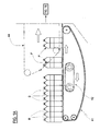
- the packing machine illustrated in figure 1 is for packing objects using a band of thin packing material wound on reels.
- the invention is especially used in a machine for enveloping packs of containers full of drinks or something else, with segments of a band of heat-retractable material.
- the machine to which the invention is applied can have different characteristics, especially depending on the type of pack being made and the type of objects packed.
- the illustrated machine comprises an advancing group which supplies a winding device 45.
- the advancing group comprises a horizontally first advancing device 41 which receives containers B (for example full plastic bottles) stacked with respect to one another, and divides them up, forming packs P made up by a predetermined number of containers, by means of a separator device 42.
- the packs P removed from the device 41 are then further distanced from one another by means of a second advancing device 44 which pushes them faster than the advancement speed of the device 41.
- the packs P are pushed by the device 44 into a wrapping device 45 (of known type) in which a segment 15 of winding band is wound about each pack.
- the segments 15 are sent to the wrapping device 45 by means of a supply group 10 from which the band 11 of the packing material originates, which reel is supported with a horizontal axis.
- the band 11 arrives in the zone of use, i.e. in the illustrated case, at the wrapping device 45, in the form of segments 15 which advance along a supply track 13.
- the supply track 13 exhibits an initial portion 13a followed by a second portion 13b of track.
- Cutting means 14 are located in the initial portion which separate the band 11 into tracts of a predetermined length to form the segments 15 of the band.
- the second portion 13b of track is defined by a conveyor belt 16, the belt 16' of which is wound about rollers 16" and exhibits an active inclined branch 16a which runs from the initial portion 13a in an upwards direction up to the start point of the wrapping device 45, and draws with it, by friction force, segments 15 of band separated by the cutting means 14 from the band 11.
- the wrapping device 45 exhibits an advancing plane 46, for example a conveyor belt 47, on which the packs P supplied by the advancement device 44 advance.
- the band segments 15 supplied by the portion of supply track 13b arrive above the advancing plane 46 by passing through a (narrow) slit 39 located between the final end of the rest plane of the advancing device 44 and the initial end of the plane 46; when the extreme initial tract of each segment 15 has passed through the slit 39, the synchronised movement of the device 44 is such that a pack P is transferred onto the plane 46 and rests on the final tract of the segment 15. From this moment the segment 15 advances together with the pack and the initial tract is imprisoned below the base of the pack P.
- a wrapping device 48 (of known type and illustrated only schematically in the figure) comprising some transversal bars 49 which are advanced continuously, drawn by an identical pair of drawing chains 51 located opposite one another and longitudinally sliding along a fixed track.
- Each bar 49 passes through the slit 39 directed from below in an upwards direction and intercepts the intermediate part of the segment 15, the initial tract of which is already imprisoned below a pack P; after this, the movement of the bar 49 produced by the chains 51 is such that the bar 49 follows the movement of the pack P and causes a wrapping of the segment 15 about the pack P up until the final end flap of the segment 15 is brought below the plane 46 through a second slit 50 afforded between the advancing plane 46 and a following advancing plane 52, located downstream. Thereafter, in the passage of the pack P from the plane 46 to the plane 52, the final flap is wound below the base of the pack P, completing the wrapping of the pack P by the segment of band 15.
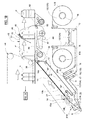
- the supply group 10 of the band 11 comprises means 17A for supporting a first reel 12 of a band 11 of thin packing material and means 17B for supporting a second reel 12 of a band 11 of thin packing material.
- the two reels 12 of band are identical and have been denoted respectively by 12A and 12B in the figures.
- the means 17A and 17B are for example constituted by usual idle rotating supports, projectingly supported with horizontal axes, of known type and only schematically illustrated in the figures, which support the spool 18 on which the reel of band is wound.
- the group 10 comprise a first track 20A for introducing the first band 11A unwinding from the first reel 12A onto the supply track 13 and respectively as second track 20B for introducing the second band 11B unwinding from the second reel 12B also onto the supply track 13.
- the tracks 20A and 20B are usual tracts along which the belt unwinding from the respective reel 12A, 12B runs stretched out along a fixed trajectory and reaches the entrance to the track 13.
- the trajectory is typically defined by various rollers, all denoted in a general sense by the letter R, of which some are idle while others are fixed and others serve as band-stretchers.
- First means for advancing 21A are located at the entrance end of the supply track 13, which first means for advancing 21A introduce or extract the front end of the first band 11A into or from the supply track 13, and second means for advancing 21B for introducing or extracting the front end of the second band 11B into or from the supply track 13.
- first and second means for advancing 21A, 21B to and from the a central roller 22 which is driven in both directions and two lateral contrast rollers 23a, 23B which are idle and can be neared and distanced on command to the central roller, each of which rollers 23a, 23b is destined to press the respective band 11 against the central roller 22.
- the central roller 22 is set in rotation, for example, by a rack 32 which is activated in a linear longitudinal motion by a linear actuator 33 (for example a pneumatic cylinder or another equivalent means), which rack engages with a pinion 34 coaxial to the roller 22; or equivalent means.
- a linear actuator 33 for example a pneumatic cylinder or another equivalent means
- the rollers 23a and 23b are pressed against or distanced from the central roller 22 by respective rotation pneumatic actuators 35 or other equivalent means.
- the cutting means comprise two opposite and counter-rotating organs 14a, 14b of which a first bears a blade which is transversal of the longitudinal direction of the band and the second is a contrast means and bears a corresponding transversal cavity into which the blade penetrates.
- a driven roller 26 is located downstream of the cutting means 14, which driven roller 26 is part of the conveyor belt 16; in particular it is located at the upstream end of the active branch 16a about which the conveyor belt 16' winds.
- the roller 26 is commanded to rotate synchronically with the roller 25 to which it is connected by means of a transmission belt 28.
- An idle contrast roller 27 is located opposite the roller 26.
- a rigid fixed plate runs between the two pairs of rollers 24, 25 and 26, 27, which plate functions as a rest for the end of the band 11 produced by the transversal cut operated by the cutting means 14.
- the plate 29 is interposed between the two organs 14a and 14b; at the line in which the blade 14a and the counter-blade 14b of the cutting means 4 act on the band 11, the plate 29 exhibits a series of transversal slits 29a through which the counter-blade 14b passes exhibiting for this purpose a series of comb-tooth-shaped recesses.
- the zone of use i.e.
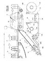
- the winding device 45 is supplied with the band 11 unwinding from one only reel 12 (for example the band 11A of reel 12A) while the other band (11B unwinding from reel 12B) is held still, with the front end HB thereof located at the initial end of the supply track 13.
- the band 11A which arrives at the supply track 13 is cut by the cutting means 14 into segments 15 of a predetermined length which is suitable for enveloping the objects P in the zone of use 45. Each cut separates a front end HA from the band 11A and, downstream thereof, a rear end of the segment 15.
- the exchange stage is started before the reel 12A being used is completely exhausted, in order to prevent the rear end of the band from advancing along the advancing track 20A.
- the exchange stage the following operations are carried out.
- the front end HA is thus pulled backwards up until it is pulled upstream of the entry of the supply track and, at the same time, the front end HB of the other band 11B is introduced into the supply track 13 where it takes the place of the finished band 11A.
- the machine then continues its normal functioning, using the band 11B coming from the new reel 12B as the supply band.
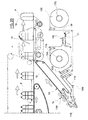
- the lateral roller 23b is brought into contact with the central roller 22, while the other lateral roller 23a was already in contact with the central roller 22 ( figure 4A ).
- Both the bands 11A and 11B are thus engaged by the respective means for advancing 21A and 21B, i.e. between rollers of the pair 23a-22 and the rollers of the pair 23b-22.
- the drawing roller 24 is then distanced from the roller 25, freeing the band 11A placed between them.
- the central roller 22 is rotated such that (in the clockwise direction in figure 4B ) while the band 11A is pulled back and its end HA is extracted from the pair of rollers 24, 25 which define the front end of the supply track 13, the exchange band 11B is advanced and its end HB is introduced between the rollers 24, 25 instead of the corresponding end HA of the band 11A, just extracted ( figure 4B ).
- the band 11A coming from the finished reel 12A (by now constituted only by the spool 18 and a few turns of band 11A) is stationary and extends along the entry track 20A up to in proximity of the entry to the supply track 13 ( figure 2A ).
- the band 11A is cut (for example with manual means and by hand) and a tail end T1 is thus defined.
- the empty reel 12A is then removed from the support 17a and a second reel 12A, new and full, is put in its place.
- a front end HA of the band 11A unwinding from the new second reel 12A is defined, the end of which is welded, by means of a traditional welding station 38 located in the zone comprised between the two supports 17A and 17B, with the tail end T1 of the preceding band 11A ( figure 2B ).
- the stage of exchanging the band 11 coming from the reel (12A or 12B) in its final stages with the band 11 of a new reel (12B or 12A) can be performed rapidly and automatically, to the point where the line operations downstream of the supply of band are not subject to any loss of rhythm.
- the only down time for the machine is for the band exchange HA-HB and not the loading of the new reel and the welding of the piece of film of the old reel present on the machine in the entry track with that of the new reel, as these operations are performed with the machine running.
Landscapes
- Engineering & Computer Science (AREA)
- Mechanical Engineering (AREA)
- Basic Packing Technique (AREA)
- Unwinding Webs (AREA)
Claims (2)
- Zuführungsgruppe eines Packbandes von Bandrollen, mit einem automatischen Austausch der Bandrolle, für eine Objektpackmaschine, umfassend:einen Zuführungsweg (13), den entlang das Packband zur Zone seiner Nutzung (45) läuft,Mittel zum Abschneiden (14) des Bandes (11) in Querrichtung, die sich am Beginn des Zuführungsweges befinden,Mittel (17A) zum Tragen einer ersten Bandrolle (12A) des Bandes (11A) aus schmalem Packmaterial und Mittel (17B) zum Tragen einer zweiten Bandrolle (12B) von Band (11 B) aus schmalem Packmaterial,einen ersten Eintrittsweg (20A) des ersten Bandes (11A) von der ersten Bandrolle (12A) zum Zuführungsweg (13),einen zweiten Eintrittsweg (20B) des zweiten Bandes (11 B) von der zweiten Bandrolle (12B) zum Zuführungsweg (13),erste Mittel zum Vorwärtsbewegen (21A) zum Einführen oder Herausziehen des vorderen Endes des ersten Bandes (11A) in den oder von dem Zuführungsweg (13),zweite Mittel zum Vorwärtsbewegen (21 B) zum Einführen oder Herausziehen des vorderen Endes des zweiten Bandes (11B) in den oder von dem Zuführungsweg (13),wobei umfasst ist, dass, während sich ein Band (11) in einem Zustand der Nutzung befindet, das andere Band (11) ortsfest ist, wobei sich sein vorderes Ende an einem Eintritt zum Zuführungsweg (13) befindet, und ferner, wenn die Bandrolle (12A, 12B), die das Band (11) zuführt, leer ist, das Band (11A, 11B) abgeschnitten wird und die Mittel zum Vorwärtsbewegen (21A, 21 B) aktiviert werden, um ein vorderes Ende des abgeschnittenen Bandes aus dem Zuführungsweg (13) herauszuziehen, während die anderen Mittel zum Vorwärtsbewegen (21 B, 21A) aktiviert werden, um ein vorderes Ende des anderen Bandes (11 B, 11A) in den Zuführungsweg (13) einzuführen, dadurch gekennzeichnet, dass die ersten Mittel zum Vorwärtsbewegen (21A) und die zweiten Mittel zum Vorwärtsbewegen (21 B) eine mittige, in zwei Richtungen angetriebene Zugwalze (22) und zwei seitliche, nicht angetriebene Gegenwalzen (23a, 23b) umfassen, die auf Befehl in Bezug auf die mittige Walze (22) hin und her angenähert und in Abstand gebracht werden können,wobei jede der beiden seitlichen, nicht angetriebenen Gegenwalzen (23a, 23b) dafür vorgesehen ist, ein jeweiliges Band (11) gegen die mittige Walze (22) zu drücken.
- Verfahren zum Betreiben einer Zuführungsgruppe eines Packbandes von Bandrollen mit einem automatischen Austausch einer Zuführungsbandrolle, mit einem Austausch der Bandrolle, für eine Objektpackmaschine, wobei die Gruppe folgende Mittel umfasst:einen Zuführungsweg (13), den entlang das Packband (11) zur Zone seiner Nutzung (45) läuft,Mittel zum Abschneiden (14) des Bandes (11) in Querrichtung, die sich am Beginn des Zuführungsweges (13) befinden,Mittel (17A) zum Tragen einer ersten Bandrolle (12A) des Bandes (11A) aus schmalem Packmaterial und Mittel (17B) zum Tragen einer zweiten Bandrolle (12B) von Band (11 B) aus schmalem Packmaterial,einen ersten Eintrittsweg (20A) des ersten Bandes (11A) von der ersten Bandrolle (12A) zum Zuführungsweg (13),einen zweiten Eintrittsweg (12B) des zweiten Bandes (11 B) von der zweiten Bandrolle (11 B) zum Zuführungsweg (13),erste Mittel zum Vorwärtsbewegen (21A) zum Einführen oder Herausziehen des vorderen Endes (HA) des ersten Bandes (11A) in den oder von dem Zuführungsweg (13),zweite Mittel zum Vorwärtsbewegen (21 B) zum Einführen oder Herausziehen eines vorderen Endes (HB) des zweiten Bandes (11 B) in den oder von dem Zuführungsweg (13),folgende Betriebsarbeitsgänge umfassend:Beschicken der Zone der Nutzung mit einem der Bänder (11A, 11B) und Ortsfest-Halten des anderen Bandes (11B, 11A), wobei sich ein vorderes Ende (HA, HE) eines der Bänder (11A, 11 B) auf dem Zuführungsweg (13) befindet,Durchführen eines Arbeitsgangs des Austauschens der Bänder (11A, 11B), wenn sich die genutzte Bandrolle in einem leer werdenden Zustand befindet, wobei in dem Arbeitsgang des Austauschens das abgeschnittene Ende (HA, HB) des Zuführungsweges (13) herausgezogen wird und ein Ende des anderen Bandes (11) in den Zuführungsweg (13) eingeführt wird,dadurch gekennzeichnet, dass das genutzte Band (11A, 11 B) durch die Schneidmittel (14) abgeschnitten wird, bevor sein hinteres Ende die Spule der Bandrolle (12A, 12B) verlässt, und danach, nachdem das andere Band (11 B, 11A) in Nutzung genommen wurde, das abgeschnittene Band ferner prozessaufwärts von seinem Eintrittsweg (20A, 20B) abgeschnitten wird und das abgeschnittene Ende (T1) an das Ende geschweißt wird, das von einer neuen Bandrolle (12) kommt, die die leere Bandrolle (12) ersetzt.
Applications Claiming Priority (1)
| Application Number | Priority Date | Filing Date | Title |
|---|---|---|---|
| ITRE2008A000120A IT1392527B1 (it) | 2008-12-24 | 2008-12-24 | Gruppo di alimentazione di nastro di confezionamento da bobine, con cambio automatico della bobina di alimentazione, per macchine per confezionare oggetti |
Publications (3)
| Publication Number | Publication Date |
|---|---|
| EP2202186A1 EP2202186A1 (de) | 2010-06-30 |
| EP2202186B1 true EP2202186B1 (de) | 2014-06-18 |
| EP2202186B8 EP2202186B8 (de) | 2023-05-24 |
Family
ID=40983381
Family Applications (1)
| Application Number | Title | Priority Date | Filing Date |
|---|---|---|---|
| EP09179679.7A Active EP2202186B8 (de) | 2008-12-24 | 2009-12-17 | Zuführungsgruppe eines Verpackungsbandes von Rollen mit automatischem Rollenwechsel für Maschinen zum Verpacken von Gegenständen |
Country Status (5)
| Country | Link |
|---|---|
| US (2) | US8544518B2 (de) |
| EP (1) | EP2202186B8 (de) |
| ES (1) | ES2502897T3 (de) |
| IT (1) | IT1392527B1 (de) |
| MX (1) | MX2009014038A (de) |
Families Citing this family (10)
| Publication number | Priority date | Publication date | Assignee | Title |
|---|---|---|---|---|
| FR2964375B1 (fr) * | 2010-09-08 | 2013-05-17 | Sidel Participations | Table d'injection d'un film plastique pour fardeleuse |
| FR2967649B1 (fr) * | 2010-11-19 | 2014-03-14 | Sidel Participations | Module de nappage pour installation de fardelage |
| FR2989668A1 (fr) * | 2012-04-18 | 2013-10-25 | Sidel Participations | Table d'injection de film pour fardeleuse |
| CN102897354A (zh) * | 2012-09-20 | 2013-01-30 | 上海普瑞福模具磨料有限公司 | 一种塑封包装方法 |
| ITMI20131550A1 (it) | 2013-09-20 | 2015-03-21 | Area S R L | Apparecchiatura per l'imballaggio di bottiglie con pellicola sottile di materiale plastico estensibile. |
| AU2016224922A1 (en) * | 2015-02-25 | 2017-08-31 | Sitma Machinery S.P.A. | Wrapping group and wrapping method for wrapping products, in particular editorial products, in containment bands |
| EP3064440B1 (de) * | 2015-03-02 | 2017-09-13 | Tetra Laval Holdings & Finance S.A. | Produktverpackungseinheit für eine verpackungsstrasse |
| ITUB20151361A1 (it) * | 2015-05-29 | 2016-11-29 | Aetna Group Spa | Macchina avvolgitrice |
| DE102016200540A1 (de) * | 2016-01-18 | 2017-07-20 | Krones Aktiengesellschaft | Vorrichtung und Verfahren zum Gruppieren und Zusammenfassen von Artikeln zu mehreren Gebinden mit unterschiedlichen Gebindegrößen |
| FR3073501A1 (fr) * | 2017-11-14 | 2019-05-17 | C.E.R.M.E.X. Constructions Etudes Et Recherches De Materiels Pour L'emballage D'expedition | Dispositif de conditionnement de produits par fardelage |
Family Cites Families (13)
| Publication number | Priority date | Publication date | Assignee | Title |
|---|---|---|---|---|
| DE1182135B (de) * | 1962-01-20 | 1964-11-19 | Theegarten Franz | Verpackungsmaschine mit Einrichtung zum Einfuehren neuer Wickelbahnen |
| US3664222A (en) * | 1970-04-07 | 1972-05-23 | Domain Ind Inc | Labeling machine |
| CS167015B1 (de) | 1973-07-24 | 1976-04-29 | ||
| IT997143B (it) | 1973-09-21 | 1975-12-30 | Seragnoli Ariosto | Apparecchiatura per produrre da materiale in nastro avvolto in bobina una successione continua di tratti di nastro o fogli partico larmente adatta per alimentare spezzoni di materiale d incarto a macchine incartatrici |
| US4342808A (en) * | 1978-12-14 | 1982-08-03 | H. J. Langen & Sons Limited | Roll stock for use in manufacture of bag |
| IT1146017B (it) * | 1981-04-09 | 1986-11-12 | Sasib Spa | Metodo e dispositivo per l alimentazione continua autoselettiva di nastri anche con tratti di scarto in un dispositivo elettronico per il taglio progressivo di bobine di carta stampata a foglietti |
| IT1145778B (it) * | 1981-06-03 | 1986-11-12 | Gd Spa | Dispositivo di alimentazione e taglio in spezzoni un nastro continuo con cambio automatico della bobina di svolgimento del nastro |
| US4720318A (en) * | 1985-08-09 | 1988-01-19 | Gang-Nail Systems, Inc. | Method and apparatus for making wooden I-beams |
| JPH0735101B2 (ja) * | 1989-06-04 | 1995-04-19 | ソマール株式会社 | 薄膜張付装置 |
| NL8902848A (nl) * | 1989-11-17 | 1991-06-17 | Tevopharm Schiedam Bv | Inrichting voor het continu toevoeren van stukken velvormig materiaal naar een verwerkingsmachine. |
| WO1994021449A1 (en) * | 1993-03-19 | 1994-09-29 | Bedford Industries, Inc. | Apparatus and method for applying a twist-tie to a packaging container |
| FR2823190B1 (fr) * | 2001-04-10 | 2003-09-05 | Cermex Ouest Conditionnement | Procede pour recharger une fardeleuse a l'aide d'un film plastique, et fardeleuse mettant en oeuvre le procede |
| DE102005000697A1 (de) * | 2005-01-04 | 2006-07-13 | Giesecke & Devrient Gmbh | Banderolenzuführvorrichtung |
-
2008
- 2008-12-24 IT ITRE2008A000120A patent/IT1392527B1/it active
-
2009
- 2009-12-17 EP EP09179679.7A patent/EP2202186B8/de active Active
- 2009-12-17 ES ES09179679.7T patent/ES2502897T3/es active Active
- 2009-12-18 MX MX2009014038A patent/MX2009014038A/es active IP Right Grant
- 2009-12-23 US US12/646,269 patent/US8544518B2/en active Active
-
2013
- 2013-08-23 US US13/974,750 patent/US8911578B2/en active Active
Also Published As
| Publication number | Publication date |
|---|---|
| MX2009014038A (es) | 2010-06-23 |
| ITRE20080120A1 (it) | 2010-06-25 |
| EP2202186B8 (de) | 2023-05-24 |
| US8911578B2 (en) | 2014-12-16 |
| US8544518B2 (en) | 2013-10-01 |
| US20130340392A1 (en) | 2013-12-26 |
| US20110000169A1 (en) | 2011-01-06 |
| EP2202186A1 (de) | 2010-06-30 |
| IT1392527B1 (it) | 2012-03-09 |
| ES2502897T3 (es) | 2014-10-06 |
Similar Documents
| Publication | Publication Date | Title |
|---|---|---|
| EP2202186B1 (de) | Zuführungsgruppe eines Verpackungsbandes von Rollen mit automatischem Rollenwechsel für Maschinen zum Verpacken von Gegenständen | |
| JP5933564B2 (ja) | ウェブ材料のロールを製造する巻取り機及び方法 | |
| US11111038B2 (en) | Perfected machine and method for packaging in extensible film products fed in groups or individually | |
| KR101275480B1 (ko) | 외부 싸개를 가진 웨브재 롤의 제조방법과 장치 | |
| US20130008995A1 (en) | Machine and method for winding reels of web material | |
| CA2937709C (en) | Device for closing the tail end of a roll of web material, and method | |
| US20080092493A1 (en) | Method for recharging a bundling machine using a plastic film and bundling machine carrying out said method | |
| US5987847A (en) | Wrapping machine and method | |
| TW201544305A (zh) | 用於製袋機之捆箍器以及用於捆箍一輥的袋件之方法 | |
| RS60500B1 (sr) | Grupa za lepljenje za mašinu za namotavanje za nanošenje lepka na krajnju ivicu kotura, mašina za namotavanje koja ima takvu grupu i povezana metoda lepljenja | |
| US7398942B2 (en) | Rewinding machine to produce logs of web material and relative winding method | |
| EP3524555B1 (de) | Vorrichtung und verfahren zum abwickeln von rollen und zum verbinden einer lage zwischen zwei rollen | |
| US11148895B2 (en) | Rewinding machine and method of producing logs of web material | |
| US10207887B2 (en) | Method and device for applying glue on tubular cores for the production of paper logs | |
| DE102004012642A1 (de) | Vorrichtung und Verfahren zur Verpackung von Produkten der Tabak verarbeitenden Industrie | |
| GB2302677A (en) | Wrapping machine and method | |
| KR20170032270A (ko) | 코드 밴드 절단용 슬리터 | |
| CA2180097A1 (en) | Wrapping machine and method | |
| GB2314545A (en) | Carousel wrapper with crimping fingers |
Legal Events
| Date | Code | Title | Description |
|---|---|---|---|
| PUAI | Public reference made under article 153(3) epc to a published international application that has entered the european phase |
Free format text: ORIGINAL CODE: 0009012 |
|
| AK | Designated contracting states |
Kind code of ref document: A1 Designated state(s): AT BE BG CH CY CZ DE DK EE ES FI FR GB GR HR HU IE IS IT LI LT LU LV MC MK MT NL NO PL PT RO SE SI SK SM TR |
|
| AX | Request for extension of the european patent |
Extension state: AL BA RS |
|
| 17P | Request for examination filed |
Effective date: 20101025 |
|
| REG | Reference to a national code |
Ref country code: DE Ref legal event code: R079 Ref document number: 602009024724 Country of ref document: DE Free format text: PREVIOUS MAIN CLASS: B65H0019100000 Ipc: B65B0021240000 |
|
| GRAP | Despatch of communication of intention to grant a patent |
Free format text: ORIGINAL CODE: EPIDOSNIGR1 |
|
| RIC1 | Information provided on ipc code assigned before grant |
Ipc: B65B 21/24 20060101AFI20140203BHEP Ipc: B65H 19/10 20060101ALI20140203BHEP Ipc: B65B 53/02 20060101ALI20140203BHEP Ipc: B65B 11/10 20060101ALI20140203BHEP |
|
| INTG | Intention to grant announced |
Effective date: 20140217 |
|
| GRAS | Grant fee paid |
Free format text: ORIGINAL CODE: EPIDOSNIGR3 |
|
| GRAA | (expected) grant |
Free format text: ORIGINAL CODE: 0009210 |
|
| AK | Designated contracting states |
Kind code of ref document: B1 Designated state(s): AT BE BG CH CY CZ DE DK EE ES FI FR GB GR HR HU IE IS IT LI LT LU LV MC MK MT NL NO PL PT RO SE SI SK SM TR |
|
| REG | Reference to a national code |
Ref country code: GB Ref legal event code: FG4D |
|
| REG | Reference to a national code |
Ref country code: CH Ref legal event code: EP |
|
| REG | Reference to a national code |
Ref country code: AT Ref legal event code: REF Ref document number: 673182 Country of ref document: AT Kind code of ref document: T Effective date: 20140715 |
|
| REG | Reference to a national code |
Ref country code: IE Ref legal event code: FG4D |
|
| REG | Reference to a national code |
Ref country code: DE Ref legal event code: R096 Ref document number: 602009024724 Country of ref document: DE Effective date: 20140731 |
|
| REG | Reference to a national code |
Ref country code: ES Ref legal event code: FG2A Ref document number: 2502897 Country of ref document: ES Kind code of ref document: T3 Effective date: 20141006 |
|
| PG25 | Lapsed in a contracting state [announced via postgrant information from national office to epo] |
Ref country code: CY Free format text: LAPSE BECAUSE OF FAILURE TO SUBMIT A TRANSLATION OF THE DESCRIPTION OR TO PAY THE FEE WITHIN THE PRESCRIBED TIME-LIMIT Effective date: 20140618 Ref country code: FI Free format text: LAPSE BECAUSE OF FAILURE TO SUBMIT A TRANSLATION OF THE DESCRIPTION OR TO PAY THE FEE WITHIN THE PRESCRIBED TIME-LIMIT Effective date: 20140618 Ref country code: LT Free format text: LAPSE BECAUSE OF FAILURE TO SUBMIT A TRANSLATION OF THE DESCRIPTION OR TO PAY THE FEE WITHIN THE PRESCRIBED TIME-LIMIT Effective date: 20140618 Ref country code: NO Free format text: LAPSE BECAUSE OF FAILURE TO SUBMIT A TRANSLATION OF THE DESCRIPTION OR TO PAY THE FEE WITHIN THE PRESCRIBED TIME-LIMIT Effective date: 20140918 Ref country code: GR Free format text: LAPSE BECAUSE OF FAILURE TO SUBMIT A TRANSLATION OF THE DESCRIPTION OR TO PAY THE FEE WITHIN THE PRESCRIBED TIME-LIMIT Effective date: 20140919 |
|
| REG | Reference to a national code |
Ref country code: NL Ref legal event code: VDEP Effective date: 20140618 |
|
| REG | Reference to a national code |
Ref country code: AT Ref legal event code: MK05 Ref document number: 673182 Country of ref document: AT Kind code of ref document: T Effective date: 20140618 |
|
| REG | Reference to a national code |
Ref country code: LT Ref legal event code: MG4D |
|
| PG25 | Lapsed in a contracting state [announced via postgrant information from national office to epo] |
Ref country code: SE Free format text: LAPSE BECAUSE OF FAILURE TO SUBMIT A TRANSLATION OF THE DESCRIPTION OR TO PAY THE FEE WITHIN THE PRESCRIBED TIME-LIMIT Effective date: 20140618 Ref country code: LV Free format text: LAPSE BECAUSE OF FAILURE TO SUBMIT A TRANSLATION OF THE DESCRIPTION OR TO PAY THE FEE WITHIN THE PRESCRIBED TIME-LIMIT Effective date: 20140618 Ref country code: HR Free format text: LAPSE BECAUSE OF FAILURE TO SUBMIT A TRANSLATION OF THE DESCRIPTION OR TO PAY THE FEE WITHIN THE PRESCRIBED TIME-LIMIT Effective date: 20140618 |
|
| PG25 | Lapsed in a contracting state [announced via postgrant information from national office to epo] |
Ref country code: PT Free format text: LAPSE BECAUSE OF FAILURE TO SUBMIT A TRANSLATION OF THE DESCRIPTION OR TO PAY THE FEE WITHIN THE PRESCRIBED TIME-LIMIT Effective date: 20141020 Ref country code: RO Free format text: LAPSE BECAUSE OF FAILURE TO SUBMIT A TRANSLATION OF THE DESCRIPTION OR TO PAY THE FEE WITHIN THE PRESCRIBED TIME-LIMIT Effective date: 20140618 Ref country code: CZ Free format text: LAPSE BECAUSE OF FAILURE TO SUBMIT A TRANSLATION OF THE DESCRIPTION OR TO PAY THE FEE WITHIN THE PRESCRIBED TIME-LIMIT Effective date: 20140618 Ref country code: EE Free format text: LAPSE BECAUSE OF FAILURE TO SUBMIT A TRANSLATION OF THE DESCRIPTION OR TO PAY THE FEE WITHIN THE PRESCRIBED TIME-LIMIT Effective date: 20140618 Ref country code: SK Free format text: LAPSE BECAUSE OF FAILURE TO SUBMIT A TRANSLATION OF THE DESCRIPTION OR TO PAY THE FEE WITHIN THE PRESCRIBED TIME-LIMIT Effective date: 20140618 |
|
| PG25 | Lapsed in a contracting state [announced via postgrant information from national office to epo] |
Ref country code: IS Free format text: LAPSE BECAUSE OF FAILURE TO SUBMIT A TRANSLATION OF THE DESCRIPTION OR TO PAY THE FEE WITHIN THE PRESCRIBED TIME-LIMIT Effective date: 20141018 Ref country code: AT Free format text: LAPSE BECAUSE OF FAILURE TO SUBMIT A TRANSLATION OF THE DESCRIPTION OR TO PAY THE FEE WITHIN THE PRESCRIBED TIME-LIMIT Effective date: 20140618 Ref country code: PL Free format text: LAPSE BECAUSE OF FAILURE TO SUBMIT A TRANSLATION OF THE DESCRIPTION OR TO PAY THE FEE WITHIN THE PRESCRIBED TIME-LIMIT Effective date: 20140618 Ref country code: NL Free format text: LAPSE BECAUSE OF FAILURE TO SUBMIT A TRANSLATION OF THE DESCRIPTION OR TO PAY THE FEE WITHIN THE PRESCRIBED TIME-LIMIT Effective date: 20140618 |
|
| REG | Reference to a national code |
Ref country code: DE Ref legal event code: R097 Ref document number: 602009024724 Country of ref document: DE |
|
| PLBE | No opposition filed within time limit |
Free format text: ORIGINAL CODE: 0009261 |
|
| STAA | Information on the status of an ep patent application or granted ep patent |
Free format text: STATUS: NO OPPOSITION FILED WITHIN TIME LIMIT |
|
| PG25 | Lapsed in a contracting state [announced via postgrant information from national office to epo] |
Ref country code: DK Free format text: LAPSE BECAUSE OF FAILURE TO SUBMIT A TRANSLATION OF THE DESCRIPTION OR TO PAY THE FEE WITHIN THE PRESCRIBED TIME-LIMIT Effective date: 20140618 |
|
| 26N | No opposition filed |
Effective date: 20150319 |
|
| PG25 | Lapsed in a contracting state [announced via postgrant information from national office to epo] |
Ref country code: BE Free format text: LAPSE BECAUSE OF FAILURE TO SUBMIT A TRANSLATION OF THE DESCRIPTION OR TO PAY THE FEE WITHIN THE PRESCRIBED TIME-LIMIT Effective date: 20140618 |
|
| PG25 | Lapsed in a contracting state [announced via postgrant information from national office to epo] |
Ref country code: SI Free format text: LAPSE BECAUSE OF FAILURE TO SUBMIT A TRANSLATION OF THE DESCRIPTION OR TO PAY THE FEE WITHIN THE PRESCRIBED TIME-LIMIT Effective date: 20140618 Ref country code: LU Free format text: LAPSE BECAUSE OF FAILURE TO SUBMIT A TRANSLATION OF THE DESCRIPTION OR TO PAY THE FEE WITHIN THE PRESCRIBED TIME-LIMIT Effective date: 20141217 |
|
| REG | Reference to a national code |
Ref country code: CH Ref legal event code: PL |
|
| REG | Reference to a national code |
Ref country code: IE Ref legal event code: MM4A |
|
| PG25 | Lapsed in a contracting state [announced via postgrant information from national office to epo] |
Ref country code: CH Free format text: LAPSE BECAUSE OF NON-PAYMENT OF DUE FEES Effective date: 20141231 Ref country code: LI Free format text: LAPSE BECAUSE OF NON-PAYMENT OF DUE FEES Effective date: 20141231 Ref country code: IE Free format text: LAPSE BECAUSE OF NON-PAYMENT OF DUE FEES Effective date: 20141217 |
|
| REG | Reference to a national code |
Ref country code: FR Ref legal event code: PLFP Year of fee payment: 7 |
|
| PG25 | Lapsed in a contracting state [announced via postgrant information from national office to epo] |
Ref country code: SM Free format text: LAPSE BECAUSE OF FAILURE TO SUBMIT A TRANSLATION OF THE DESCRIPTION OR TO PAY THE FEE WITHIN THE PRESCRIBED TIME-LIMIT Effective date: 20140618 |
|
| PG25 | Lapsed in a contracting state [announced via postgrant information from national office to epo] |
Ref country code: MC Free format text: LAPSE BECAUSE OF FAILURE TO SUBMIT A TRANSLATION OF THE DESCRIPTION OR TO PAY THE FEE WITHIN THE PRESCRIBED TIME-LIMIT Effective date: 20140618 |
|
| PG25 | Lapsed in a contracting state [announced via postgrant information from national office to epo] |
Ref country code: BG Free format text: LAPSE BECAUSE OF FAILURE TO SUBMIT A TRANSLATION OF THE DESCRIPTION OR TO PAY THE FEE WITHIN THE PRESCRIBED TIME-LIMIT Effective date: 20140618 |
|
| PG25 | Lapsed in a contracting state [announced via postgrant information from national office to epo] |
Ref country code: MT Free format text: LAPSE BECAUSE OF FAILURE TO SUBMIT A TRANSLATION OF THE DESCRIPTION OR TO PAY THE FEE WITHIN THE PRESCRIBED TIME-LIMIT Effective date: 20140618 Ref country code: TR Free format text: LAPSE BECAUSE OF FAILURE TO SUBMIT A TRANSLATION OF THE DESCRIPTION OR TO PAY THE FEE WITHIN THE PRESCRIBED TIME-LIMIT Effective date: 20140618 Ref country code: HU Free format text: LAPSE BECAUSE OF FAILURE TO SUBMIT A TRANSLATION OF THE DESCRIPTION OR TO PAY THE FEE WITHIN THE PRESCRIBED TIME-LIMIT; INVALID AB INITIO Effective date: 20091217 |
|
| REG | Reference to a national code |
Ref country code: FR Ref legal event code: PLFP Year of fee payment: 8 |
|
| REG | Reference to a national code |
Ref country code: FR Ref legal event code: PLFP Year of fee payment: 9 |
|
| PG25 | Lapsed in a contracting state [announced via postgrant information from national office to epo] |
Ref country code: MK Free format text: LAPSE BECAUSE OF FAILURE TO SUBMIT A TRANSLATION OF THE DESCRIPTION OR TO PAY THE FEE WITHIN THE PRESCRIBED TIME-LIMIT Effective date: 20140618 |
|
| GRAT | Correction requested after decision to grant or after decision to maintain patent in amended form |
Free format text: ORIGINAL CODE: EPIDOSNCDEC |
|
| P01 | Opt-out of the competence of the unified patent court (upc) registered |
Effective date: 20230502 |
|
| PGFP | Annual fee paid to national office [announced via postgrant information from national office to epo] |
Ref country code: DE Payment date: 20241227 Year of fee payment: 16 |
|
| PGFP | Annual fee paid to national office [announced via postgrant information from national office to epo] |
Ref country code: ES Payment date: 20250102 Year of fee payment: 16 |
|
| PGFP | Annual fee paid to national office [announced via postgrant information from national office to epo] |
Ref country code: IT Payment date: 20250926 Year of fee payment: 17 |
|
| PGFP | Annual fee paid to national office [announced via postgrant information from national office to epo] |
Ref country code: GB Payment date: 20251229 Year of fee payment: 17 |
|
| PGFP | Annual fee paid to national office [announced via postgrant information from national office to epo] |
Ref country code: FR Payment date: 20251226 Year of fee payment: 17 |