EP2202111A2 - Engine speed calculation device and engine sound generation device - Google Patents
Engine speed calculation device and engine sound generation device Download PDFInfo
- Publication number
- EP2202111A2 EP2202111A2 EP09015954A EP09015954A EP2202111A2 EP 2202111 A2 EP2202111 A2 EP 2202111A2 EP 09015954 A EP09015954 A EP 09015954A EP 09015954 A EP09015954 A EP 09015954A EP 2202111 A2 EP2202111 A2 EP 2202111A2
- Authority
- EP
- European Patent Office
- Prior art keywords
- engine speed
- vehicle
- speed
- engine
- virtual
- Prior art date
- Legal status (The legal status is an assumption and is not a legal conclusion. Google has not performed a legal analysis and makes no representation as to the accuracy of the status listed.)
- Granted
Links
- 230000001419 dependent effect Effects 0.000 claims abstract description 11
- 230000001133 acceleration Effects 0.000 abstract description 13
- 230000006399 behavior Effects 0.000 abstract description 5
- 230000005540 biological transmission Effects 0.000 description 4
- 238000010586 diagram Methods 0.000 description 2
- 230000002411 adverse Effects 0.000 description 1
- 230000003247 decreasing effect Effects 0.000 description 1
- 230000007613 environmental effect Effects 0.000 description 1
- 239000000446 fuel Substances 0.000 description 1
- 238000004519 manufacturing process Methods 0.000 description 1
- 230000004044 response Effects 0.000 description 1
Images



Classifications
-
- B—PERFORMING OPERATIONS; TRANSPORTING
- B60—VEHICLES IN GENERAL
- B60L—PROPULSION OF ELECTRICALLY-PROPELLED VEHICLES; SUPPLYING ELECTRIC POWER FOR AUXILIARY EQUIPMENT OF ELECTRICALLY-PROPELLED VEHICLES; ELECTRODYNAMIC BRAKE SYSTEMS FOR VEHICLES IN GENERAL; MAGNETIC SUSPENSION OR LEVITATION FOR VEHICLES; MONITORING OPERATING VARIABLES OF ELECTRICALLY-PROPELLED VEHICLES; ELECTRIC SAFETY DEVICES FOR ELECTRICALLY-PROPELLED VEHICLES
- B60L3/00—Electric devices on electrically-propelled vehicles for safety purposes; Monitoring operating variables, e.g. speed, deceleration or energy consumption
-
- B—PERFORMING OPERATIONS; TRANSPORTING
- B60—VEHICLES IN GENERAL
- B60Q—ARRANGEMENT OF SIGNALLING OR LIGHTING DEVICES, THE MOUNTING OR SUPPORTING THEREOF OR CIRCUITS THEREFOR, FOR VEHICLES IN GENERAL
- B60Q5/00—Arrangement or adaptation of acoustic signal devices
- B60Q5/005—Arrangement or adaptation of acoustic signal devices automatically actuated
- B60Q5/008—Arrangement or adaptation of acoustic signal devices automatically actuated for signaling silent vehicles, e.g. for warning that a hybrid or electric vehicle is approaching
-
- G—PHYSICS
- G10—MUSICAL INSTRUMENTS; ACOUSTICS
- G10K—SOUND-PRODUCING DEVICES; METHODS OR DEVICES FOR PROTECTING AGAINST, OR FOR DAMPING, NOISE OR OTHER ACOUSTIC WAVES IN GENERAL; ACOUSTICS NOT OTHERWISE PROVIDED FOR
- G10K15/00—Acoustics not otherwise provided for
- G10K15/02—Synthesis of acoustic waves
Definitions
- the present invention relates to engine speed calculation devices and engine sound generation devices for generating engine sound simulated in traveling conditions of four-wheeled vehicles and motorcycles.
- the present invention is directed to an engine sound generation device including an accelerator opening sensor detecting an accelerator opening of a vehicle, a vehicle speed sensor detecting a vehicle speed of the vehicle, a vehicle-nondependent engine speed memory storing a virtual engine speed which depends upon the accelerator opening but does not depend upon the vehicle speed in advance, and an engine speed calculation unit acquiring the virtual engine speed from the vehicle-nondependent engine speed memory in correspondence with the accelerator opening on the condition that the virtual engine speed is not deemed proportional to the vehicle speed. It the engine sound generation device further includes an engine sound generation unit which artificially generates an engine sound based on the virtual engine speed.
- the engine speed calculation unit calculates the virtual engine speed without using the vehicle speed and with reference to the vehicle-nondependent engine speed memory on the condition that the virtual engine speed is not proportional to the vehicle speed. This prevents the virtual engine speed calculation unit from miscalculating the virtual engine speed based on the vehicle speed which is not proportional to the virtual engine speed, thus prevent the artificially affected engine sound from being produced based on the miscalculated virtual engine speed.
- the engine sound generation device of the present invention is capable of generating the common engine speed matching the behavior of an engine in an electric vehicle driven by an electric motor.
- the vehicle-nondependent engine speed memory stores a table of time-related variations of the virtual engine speed in connection to the accelerator opening, thus allowing the engine speed calculation unit to read the virtual engine speed from the table in correspondence with the accelerator opening and an elapsed time.
- the vehicle-nondependent engine speed memory stores a table of an engine speed increase rate in connection to the accelerator opening, thus allowing the engine speed calculation unit to read the engine speed increase rate from the table in correspondence with the accelerator opening and to thereby calculate the virtual engine speed by use of an elapsed time.
- the virtual engine speed is varied continuously with respect to time while following up with variations of the accelerator opening. In other words, it is possible to prevent the virtual engine speed from being varied discontinuously, thus precisely calculating the virtual engine speed nondependent upon the vehicle speed.
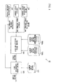
- Fig. 1 is a block diagram showing the constitution of an engine sound generation device 10 according to a first embodiment of the present invention.
- the engine sound generation device 10 is constituted of a motor revolution speed sensor 101, a vehicle speed sensor 102, an accelerator opening sensor 103, an engine speed calculation unit 104, an engine sound generation unit 105, a vehicle-nondependent engine speed memory 106a, a vehicle-dependent engine speed memory 106b, and an engine sound memory 107.
- the following description is related to an electric vehicle equipped with an electric motor only, in which the terms such as engine and transmission are used as imaginary factors.
- the motor revolution speed sensor 101 detects the revolution speed of an electric motor (serving as a driving source of a four-wheeled vehicle) so as to produce motor revolution speed information.
- the vehicle speed sensor 102 detects the revolution speed of wheels of the vehicle so as to produce vehicle speed information.
- the accelerator opening sensor 103 detects the depression of an accelerator pedal (not shown) so as to produce accelerator opening information.
- the first embodiment detects the accelerator opening in sixteen ranges denoted by "0" to "15", in which a larger range represents a deeper depression of an accelerator pedal.
- All the motor revolution speed information, the vehicle speed information, and the accelerator opening information are supplied to the engine speed calculation unit 104 from the motor revolution speed sensor 101, the vehicle speed sensor 102, and the acceleration opening sensor 103.
- the acceleration opening information of the acceleration opening sensor 103 is supplied to the engine sound generation unit 105 as well.
- the engine speed calculation unit 104 refers to the vehicle-nondependent engine speed memory 106a or the vehicle-dependent engine speed memory 106b based on the motor revolution speed information, the vehicle speed information, and the acceleration opening information, thus acquiring a virtual engine speed.
- the virtual engine speed is supplied to the engine sound generation unit 105. That is, the engine speed calculation unit 104 estimates whether or not the virtual engine speed is deemed proportional to the vehicle speed based on the motor revolution speed information, the vehicle speed information, and the accelerator opening information.
- the engine speed calculation unit 104 estimates that the virtual engine speed is not deemed proportional to the vehicle speed, for example, at startup of a vehicle or in the semi-engagement of a clutch (which presumably occurs in an engine-driven vehicle), it retrieves a desired value of the virtual engine speed from the vehicle-nondependent engine speed memory 106a which stores various values of the virtual engine speed dependent upon the accelerator opening but not dependent upon the vehicle speed. In a nondependent state, the same value of the virtual engine speed is assigned to various values of the vehicle speed. When the engine speed calculation unit 104 estimates that the virtual engine speed is deemed proportional to the vehicle speed, it retrieves another value of the virtual engine speed, which is dependent upon both the accelerator opening and the vehicle speed, from the vehicle-dependent engine speed memory 106b.
- the engine sound generation unit 105 Based on the virtual engine speed and the accelerator opening information, the engine sound generation unit 105 refers to the engine sound memory 107 so as to generate a voltage signal representing a sound-pressure waveform of an engine sound.
- the voltage signal is supplied to an external speaker (not shown).
- Fig. 2 is a graph exemplifying data stored in the vehicle-nondependent engine speed memory 106a in connection with a table of the relationship between the accelerator opening and the virtual engine speed, wherein the horizontal axis represents the accelerator opening, and the vertical axis represents the virtual engine speed in units of 1,000 rpm.
- Fig. 2 shows that a low engine speed is assigned to a low accelerator opening, and a high engine speed is assigned to a high accelerator opening.
- the engine speed calculation unit 104 determines that the virtual engine speed does not vary in proportion to the vehicle speed, it reads the virtual engine speed from the above table (see the illustration of Fig. 2 ) in correspondence with the accelerator opening information, thus supplying the read virtual engine speed to the engine sound generation unit 105.
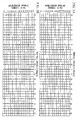
- Figs. 3A and 3B show the contents of tables storing speeds (i.e. gear-selector positions ranging from “1" to "5" in a five-gear transmission) in connection to the vehicle speed (ranging from “0" to "20" x 10 km/h) and the accelerator opening (ranging from “0" to "15).
- the table of Fig. 3A is used in an acceleration mode of the vehicle, while the table of Fig. 3B is used in a deceleration mode of the vehicle.
- the reason why the different tables are used for the acceleration mode and the deceleration mode is to prevent the gear-selector position from being frequently shifted when the vehicle speed is repeatedly increased and decreased in a small range of speed.
- the engine speed calculation unit 104 estimates that the virtual engine speed is deemed proportional to the vehicle speed, it adopts either the acceleration-mode table of Fig. 3A or the deceleration-mode table of Fig. 3B , thus reading out the number of speeds in connection to the acceleration opening information and the vehicle speed information.
- the vehicle speed "0" ranges from 0 km/h to 10 km/h
- vehicle speed "1” ranges from 10 km/h to 20 km/h.
- Table 1 defines the relationship between the speed (i.e. the gear-selector position) and the gear ratio, wherein the gear ratio is the ratio of the virtual engine speed (or the transmission input) to the engine speed (or the transmission output).
- the engine speed calculation unit 104 uses the speed read from the table of Fig. 3A or Fig. 3B to read the corresponding gear ratio from Table 1,
- Fig. 4 exemplifies the stored data of the engine sound memory 107 in a table storing sound-pressure waveforms of engine sound in connection to the virtual engine speed and the acceleration opening.
- Sound-pressure waveforms of engine sound are digital data which are produced by recording actual engine sounds of engine-driven vehicles in advance.
- Fig. 4 shows five waveforms 1 to 5 in five conditions related to different virtual engine speeds and different accelerator openings, wherein the horizontal axis represents the virtual engine speed in units of 1,000 rpm, and the vertical axis represents the acceleration opening.
- the engine sound generation unit 105 reads the corresponding sound-pressure waveform from Fig. 4 .
- three sound-pressure waveforms i.e, the waveforms 1 to 3 which are proximate to the point P
- the three waveforms 1 to 3 are mixed with respective weights corresponding to their distances from the point P.
- Preset data are produced in advance in the manufacturing of a four-wheeled vehicle and stored in the vehicle-nondependent engine speed memory 106a, the vehicle-dependent engine speed memory 106b, and the engine sound memory 107 (see Fig. 2 , Figs. 3A and 3B , and Table 1).
- the motor revolution speed sensor 101, the vehicle speed sensor 102, and the accelerator opening sensor 103 normally perform sensing operations, thus detecting the traveling condition of a vehicle.
- the engine speed calculation unit 104 determines whether or not the virtual engine speed varies in proportion to the vehicle speed. For example, when the motor revolution speed does not vary in proportion to the vehicle speed, or when the vehicle speed is lower than a predetermined threshold value, it is determined that the virtual engine speed does not vary in proportion to the vehicle speed. When it is determined that the virtual engine speed varies in proportion to the vehicle speed, the flow proceeds to step S3. When it is determined that the virtual engine speed does not vary in proportion to the vehicle speed, the flow proceeds to step S4.
- the engine speed calculation unit 104 refers to the tables shown in Figs. 3A and 3B and Table 1 so as to calculate the virtual engine speed. Specifically, the engine speed calculation unit 104 reads the speed from the table of Fig. 3A or 3B in correspondence with the accelerator opening and the vehicle speed, and then it reads the gear ratio from Table 1 in correspondence with the speed.
- the engine speed calculation unit 104 calculates the virtual engine speed "Ne” using the following equation, in which "V” denotes the vehicle speed, “R” denotes a driving radius of a wheel (or a tire wheel), “it” denotes the gear ratio, and “if' denotes the final reduction gear ratio which is a prefixed gear ratio.
- Ne it ⁇ if 2 ⁇ ⁇ R ⁇ 60 / 1000 ⁇ V
- the engine speed calculation unit 104 refers to the table of Fig. 2 so as to calculate the virtual engine speed. Specifically, the engine speed calculation unit 104 reads the virtual engine speed from the table of Fig. 2 in correspondence with the accelerator opening.
- the virtual engine speed calculated in step S3 or step S4 is supplied to the engine sound generation unit 105.
- the engine sound generation unit 105 refers to the engine sound memory 107 so as to generate a sound-pressure waveform of the engine sound.
- a voltage signal representative of the sound-pressure waveform of the engine sound is supplied to a speaker (not shown) so as to generate the engine sound.
- the first embodiment is characterized in that when it is determined that the virtual engine speed does not vary in proportion to the vehicle speed, the engine speed calculation unit 104 reads the virtual engine speed from the predetermined table of Fig. 2 , so that the engine sound generation unit 105 correspondingly generates the voltage signal representative of the sound-pressure waveform of the engine sound.
- the engine speed calculation unit 104 calculates the virtual engine speed without using the vehicle speed information, This prevents the engine sound generation device 10 from generating an artificially affected engine sound based on the virtual engine speed which is miscalculated in response to the vehicle speed though the virtual engine speed does not vary in proportion to the vehicle speed.
- the virtual engine speed does not vary in proportion to the vehicle speed (in the semi-engagement of the clutch, for instance) while the vehicle speed is increased from 0 km/h to reach 10 km/h.
- the second embodiment introduces a table identifying the correspondence between the accelerator opening and the virtual engine speed (which varies with respect to time), with which the engine speed calculation unit 104 calculates the virtual engine speed.
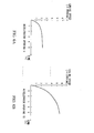
- Figs. 6A and 6B shows the tables of time-related variations of the virtual engine speed, which is stored in the vehicle-nondependent engine speed memory 106a, wherein the horizontal axis represents the time in units of seconds, and the vertical axis represents the virtual engine speed in units of 1,000 rpm.
- Fig. 6A shows time-related variations of the virtual engine speed in the accelerator opening range "0”
- Fig. 6B shows time-related variations of the virtual engine speed in the accelerator opening range "15”.
- a low engine speed increase rate is allocated to a low accelerator opening range
- a high engine speed increase rate is allocated to a high accelerator opening range.
- the engine speed calculation unit 104 reads the virtual engine speed at the lapsed time from the table corresponding to the accelerator opening presently designated by the accelerator opening information.
- the second embodiment is designed such that at startup of the vehicle, the engine speed calculation unit 104 calculates the virtual engine speed with reference to the predetermined tables of Fig. 6A and Fig. 6B based on the accelerator opening and the elapsed time.
- the engine speed calculation unit 104 calculates the virtual engine speed with reference to the predetermined tables of Fig. 6A and Fig. 6B based on the accelerator opening and the elapsed time.
- the third embodiment is characterized in that the engine speed calculation unit 104 refers to the predetermined relationship between the accelerator opening and the virtual engine speed increase rate on the condition that the virtual engine speed does not vary in proportion to the vehicle speed.
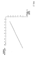
- Fig. 7 is a graph showing the content of a table stored in the vehicle-nondependent engine speed memory 106a, wherein the horizontal axis represents the accelerator opening (e.g. ranges 1-10), and the vertical axis represents the engine speed increase rate in units of 1,000 rpm/s, thus showing linear variations of the engine speed increase rate in connection to the accelerator opening.
- a low engine speed increase rate is allocated to a low accelerator opening
- a high engine speed increase rate is allocated to a high accelerator opening.
- the engine speed calculation unit 104 reads the engine speed increase rate from the table of Fig. 7 in correspondence with the accelerator opening designated by the accelerator opening information, thus calculating the virtual engine speed in consideration of the engine speed increase rate. Specifically, the engine speed calculation unit 104 multiplies the engine speed increase rate and the elapsed time (which is elapsed from the previous time for calculating the virtual engine speed) so as to produce an increase value, which is then added to the previously calculated virtual engine speed, thus producing the "present" virtual engine speed.
- the present virtual engine speed is supplied to the engine sound generation unit 105, thus producing the corresponding engine sound.
- the third embodiment is designed such that the engine speed calculation unit 104 reads the engine speed increase rate from the table of Fig. 7 in correspondence with the accelerator opening on the condition that the virtual engine speed does not vary in proportion to the vehicle speed, thus calculating the virtual engine speed.
- the third embodiment is advantageous in that the virtual engine speed does not vary discontinuously with the accelerator opening. Thus, it is possible to precisely calculate the virtual engine speed.
- the virtual engine speed is not proportional to the vehicle speed when an antilock braking system (ABS) of a vehicle detects quick braking made by a driver.
- ABS antilock braking system
- the virtual engine speed is not proportional to the vehicle speed when a clutch-state sensor of a vehicle detects the semi-engagement of a clutch.
- the present invention is applied not only to vehicles which actually travel on roads but also to drive simulators which virtually reproduce driving/traveling conditions of vehicles.
Landscapes
- Engineering & Computer Science (AREA)
- Mechanical Engineering (AREA)
- Acoustics & Sound (AREA)
- Physics & Mathematics (AREA)
- Audiology, Speech & Language Pathology (AREA)
- Transportation (AREA)
- Power Engineering (AREA)
- Health & Medical Sciences (AREA)
- Life Sciences & Earth Sciences (AREA)
- General Health & Medical Sciences (AREA)
- Sustainable Energy (AREA)
- Sustainable Development (AREA)
- Multimedia (AREA)
- Combined Controls Of Internal Combustion Engines (AREA)
- Fittings On The Vehicle Exterior For Carrying Loads, And Devices For Holding Or Mounting Articles (AREA)
- Electric Propulsion And Braking For Vehicles (AREA)
- Control Of Vehicle Engines Or Engines For Specific Uses (AREA)
Abstract
Description
- The present invention relates to engine speed calculation devices and engine sound generation devices for generating engine sound simulated in traveling conditions of four-wheeled vehicles and motorcycles.
- The present application claims priority on Japanese Patent Application No.
2008-334233 - Recently, electric vehicles driven by electric motors and hybrid vehicles driven by engines and electric motors have widely spread among people highly concerned with environmental conservation. Compared to conventional four-wheeled vehicles, electric vehicles and hybrid vehicles are advantageous in that they generate very small noise while traveling. This adversely causes a traffic problem in that pedestrians may hardly notice electric vehicles approaching them. Since engine-driven vehicles differ from electric vehicles in sounds generated during driving at the same velocity, drivers who are accustomed to engine-driven vehicles but are not accustomed to electric vehicles may have a sense of incongruity in driving electric vehicles. To solve such a drawback, various devices are developed to calculate virtual engine speeds based on parameters such as accelerator openings (e.g. throttle valve openings, fuel injector valve openings, depressions of accelerator pedals) and traveling speeds of vehicles and to thereby generate pseudo engine sounds as alarm sounds based on virtual engine speeds.
Patent Document 1 discloses a simulated engine sound generating device. - Patent Document 1: Japanese Unexamined Patent Application Publication No.
2000-10576 -
Patent Document 1 simply discloses a device which calculates virtual engine speed based on the traveling speed of a vehicle; hence, when the actual traveling speed does not vary in proportion to the virtual engine speed at startup of a vehicle or in a semi-engagement of a clutch, the generated engine sound (or alarm sound) may be heard as an artificially affected sound. - It is an object of the present invention to provide an engine speed calculation device and an engine sound generation device, which are capable of generating an artificial engine sound close to the actual engine sound produced by an engine-driven vehicle even when the calculated engine speed does not vary in proportion to the traveling speed of a vehicle such as an electric vehicle and a hybrid vehicle.
- The present invention is directed to an engine sound generation device including an accelerator opening sensor detecting an accelerator opening of a vehicle, a vehicle speed sensor detecting a vehicle speed of the vehicle, a vehicle-nondependent engine speed memory storing a virtual engine speed which depends upon the accelerator opening but does not depend upon the vehicle speed in advance, and an engine speed calculation unit acquiring the virtual engine speed from the vehicle-nondependent engine speed memory in correspondence with the accelerator opening on the condition that the virtual engine speed is not deemed proportional to the vehicle speed. It the engine sound generation device further includes an engine sound generation unit which artificially generates an engine sound based on the virtual engine speed.
- In the above, the engine speed calculation unit calculates the virtual engine speed without using the vehicle speed and with reference to the vehicle-nondependent engine speed memory on the condition that the virtual engine speed is not proportional to the vehicle speed. This prevents the virtual engine speed calculation unit from miscalculating the virtual engine speed based on the vehicle speed which is not proportional to the virtual engine speed, thus prevent the artificially affected engine sound from being produced based on the miscalculated virtual engine speed. In other words, the engine sound generation device of the present invention is capable of generating the common engine speed matching the behavior of an engine in an electric vehicle driven by an electric motor.
- In addition, the vehicle-nondependent engine speed memory stores a table of time-related variations of the virtual engine speed in connection to the accelerator opening, thus allowing the engine speed calculation unit to read the virtual engine speed from the table in correspondence with the accelerator opening and an elapsed time.
- Alternatively, the vehicle-nondependent engine speed memory stores a table of an engine speed increase rate in connection to the accelerator opening, thus allowing the engine speed calculation unit to read the engine speed increase rate from the table in correspondence with the accelerator opening and to thereby calculate the virtual engine speed by use of an elapsed time. The virtual engine speed is varied continuously with respect to time while following up with variations of the accelerator opening. In other words, it is possible to prevent the virtual engine speed from being varied discontinuously, thus precisely calculating the virtual engine speed nondependent upon the vehicle speed.
- These and other objects, aspects, and embodiments of the present invention will be described in more detail with reference to the following drawings.
-
Fig. 1 is a block diagram showing the constitution of an engine sound generation device according to a first embodiment of the present invention. -
Fig, 2 is a graph exemplifying the relationship between the accelerator opening and the virtual engine speed. -
Fig. 3A shows a table storing the speed in connection to the vehicle speed and the acceleration opening in an acceleration mode of a vehicle. -
Fig. 3B shows a table storing the speed in connection to the vehicle speed and the acceleration opening in a deceleration mode of the vehicle. -
Fig. 4 is a graph showing sound-pressure waveforms in connection to the virtual engine speed and the accelerator opening. -
Fig. 5 is a flowchart used for explaining the operation of the engine sound generation device of the first embodiment. -
Fig. 6A is a graph showing time-related variations of the virtual engine speed in an accelerator opening range "0" in a second embodiment of the present invention. -
Fig. 6B is a graph showing time-related variations of the virtual engine speed in an accelerator opening range "15" in the second embodiment of the present invention. -
Fig. 7 is a graph showing the relationship between the accelerator opening and the virtual engine speed increase rate in a third embodiment of the present invention. - The present invention will be described in further detail by way of examples with reference to the accompanying drawings.
-
Fig. 1 is a block diagram showing the constitution of an enginesound generation device 10 according to a first embodiment of the present invention. - The engine
sound generation device 10 is constituted of a motorrevolution speed sensor 101, avehicle speed sensor 102, anaccelerator opening sensor 103, an enginespeed calculation unit 104, an enginesound generation unit 105, a vehicle-nondependentengine speed memory 106a, a vehicle-dependentengine speed memory 106b, and anengine sound memory 107. The following description is related to an electric vehicle equipped with an electric motor only, in which the terms such as engine and transmission are used as imaginary factors. - The motor
revolution speed sensor 101 detects the revolution speed of an electric motor (serving as a driving source of a four-wheeled vehicle) so as to produce motor revolution speed information. Thevehicle speed sensor 102 detects the revolution speed of wheels of the vehicle so as to produce vehicle speed information. Theaccelerator opening sensor 103 detects the depression of an accelerator pedal (not shown) so as to produce accelerator opening information. The first embodiment detects the accelerator opening in sixteen ranges denoted by "0" to "15", in which a larger range represents a deeper depression of an accelerator pedal. - All the motor revolution speed information, the vehicle speed information, and the accelerator opening information are supplied to the engine
speed calculation unit 104 from the motorrevolution speed sensor 101, thevehicle speed sensor 102, and theacceleration opening sensor 103. The acceleration opening information of theacceleration opening sensor 103 is supplied to the enginesound generation unit 105 as well. - The engine
speed calculation unit 104 refers to the vehicle-nondependentengine speed memory 106a or the vehicle-dependentengine speed memory 106b based on the motor revolution speed information, the vehicle speed information, and the acceleration opening information, thus acquiring a virtual engine speed. The virtual engine speed is supplied to the enginesound generation unit 105. That is, the enginespeed calculation unit 104 estimates whether or not the virtual engine speed is deemed proportional to the vehicle speed based on the motor revolution speed information, the vehicle speed information, and the accelerator opening information. When the enginespeed calculation unit 104 estimates that the virtual engine speed is not deemed proportional to the vehicle speed, for example, at startup of a vehicle or in the semi-engagement of a clutch (which presumably occurs in an engine-driven vehicle), it retrieves a desired value of the virtual engine speed from the vehicle-nondependentengine speed memory 106a which stores various values of the virtual engine speed dependent upon the accelerator opening but not dependent upon the vehicle speed. In a nondependent state, the same value of the virtual engine speed is assigned to various values of the vehicle speed. When the enginespeed calculation unit 104 estimates that the virtual engine speed is deemed proportional to the vehicle speed, it retrieves another value of the virtual engine speed, which is dependent upon both the accelerator opening and the vehicle speed, from the vehicle-dependentengine speed memory 106b. - Based on the virtual engine speed and the accelerator opening information, the engine
sound generation unit 105 refers to theengine sound memory 107 so as to generate a voltage signal representing a sound-pressure waveform of an engine sound. The voltage signal is supplied to an external speaker (not shown). -
Fig. 2 is a graph exemplifying data stored in the vehicle-nondependentengine speed memory 106a in connection with a table of the relationship between the accelerator opening and the virtual engine speed, wherein the horizontal axis represents the accelerator opening, and the vertical axis represents the virtual engine speed in units of 1,000 rpm.Fig. 2 shows that a low engine speed is assigned to a low accelerator opening, and a high engine speed is assigned to a high accelerator opening. When the enginespeed calculation unit 104 determines that the virtual engine speed does not vary in proportion to the vehicle speed, it reads the virtual engine speed from the above table (see the illustration ofFig. 2 ) in correspondence with the accelerator opening information, thus supplying the read virtual engine speed to the enginesound generation unit 105. - Next, the contents of the vehicle-dependent
engine speed memory 106b will be described in conjunction withFigs. 3A and 3B and Table 1. -
Figs. 3A and 3B show the contents of tables storing speeds (i.e. gear-selector positions ranging from "1" to "5" in a five-gear transmission) in connection to the vehicle speed (ranging from "0" to "20" x 10 km/h) and the accelerator opening (ranging from "0" to "15). The table ofFig. 3A is used in an acceleration mode of the vehicle, while the table ofFig. 3B is used in a deceleration mode of the vehicle. The reason why the different tables are used for the acceleration mode and the deceleration mode is to prevent the gear-selector position from being frequently shifted when the vehicle speed is repeatedly increased and decreased in a small range of speed. When the enginespeed calculation unit 104 estimates that the virtual engine speed is deemed proportional to the vehicle speed, it adopts either the acceleration-mode table ofFig. 3A or the deceleration-mode table ofFig. 3B , thus reading out the number of speeds in connection to the acceleration opening information and the vehicle speed information. In the horizontal axes ofFigs. 3A and 3B , the vehicle speed "0" ranges from 0 km/h to 10 km/h, and vehicle speed "1" ranges from 10 km/h to 20 km/h.Table 1 Speed (Gear-Selector Position) Gear Ratio 1 3.5 2 2.6 3 1.4 4 1 5 0.75 - Table 1 defines the relationship between the speed (i.e. the gear-selector position) and the gear ratio, wherein the gear ratio is the ratio of the virtual engine speed (or the transmission input) to the engine speed (or the transmission output). Using the speed read from the table of
Fig. 3A or Fig. 3B , the enginespeed calculation unit 104 reads the corresponding gear ratio from Table 1, -
Fig. 4 exemplifies the stored data of theengine sound memory 107 in a table storing sound-pressure waveforms of engine sound in connection to the virtual engine speed and the acceleration opening. Sound-pressure waveforms of engine sound are digital data which are produced by recording actual engine sounds of engine-driven vehicles in advance.Fig. 4 shows fivewaveforms 1 to 5 in five conditions related to different virtual engine speeds and different accelerator openings, wherein the horizontal axis represents the virtual engine speed in units of 1,000 rpm, and the vertical axis represents the acceleration opening. Based on the accelerator opening information and the virtual engine speed, the enginesound generation unit 105 reads the corresponding sound-pressure waveform fromFig. 4 . At a point P indicating the virtual engine speed xl and the accelerator opening yl, three sound-pressure waveforms (i.e, thewaveforms 1 to 3 which are proximate to the point P) are selected and mixed together to form a desired sound-pressure waveform of engine sound. The threewaveforms 1 to 3 are mixed with respective weights corresponding to their distances from the point P. - Preset data are produced in advance in the manufacturing of a four-wheeled vehicle and stored in the vehicle-nondependent
engine speed memory 106a, the vehicle-dependentengine speed memory 106b, and the engine sound memory 107 (seeFig. 2 ,Figs. 3A and 3B , and Table 1). - Next, the operation of the engine
sound generation device 10 will be described with reference toFig. 5 . - During the operating state of the engine
sound generation device 10, the motorrevolution speed sensor 101, thevehicle speed sensor 102, and theaccelerator opening sensor 103 normally perform sensing operations, thus detecting the traveling condition of a vehicle. - All the motor revolution speed information, the vehicle speed information, and the accelerator opening information representative of the traveling condition of the vehicle (detected in step S1) are supplied to the engine
speed calculation unit 104. In accordance with the motor revolution speed information and the vehicle speed information, the enginespeed calculation unit 104 determines whether or not the virtual engine speed varies in proportion to the vehicle speed. For example, when the motor revolution speed does not vary in proportion to the vehicle speed, or when the vehicle speed is lower than a predetermined threshold value, it is determined that the virtual engine speed does not vary in proportion to the vehicle speed. When it is determined that the virtual engine speed varies in proportion to the vehicle speed, the flow proceeds to step S3. When it is determined that the virtual engine speed does not vary in proportion to the vehicle speed, the flow proceeds to step S4. - When it is determined that the virtual engine speed varies in proportion to the vehicle speed, the engine
speed calculation unit 104 refers to the tables shown inFigs. 3A and 3B and Table 1 so as to calculate the virtual engine speed. Specifically, the enginespeed calculation unit 104 reads the speed from the table ofFig. 3A or 3B in correspondence with the accelerator opening and the vehicle speed, and then it reads the gear ratio from Table 1 in correspondence with the speed. Subsequently, the enginespeed calculation unit 104 calculates the virtual engine speed "Ne" using the following equation, in which "V" denotes the vehicle speed, "R" denotes a driving radius of a wheel (or a tire wheel), "it" denotes the gear ratio, and "if' denotes the final reduction gear ratio which is a prefixed gear ratio. When the virtual engine speed Ne is smaller than "600", the enginespeed calculation unit 104 determines that the engine of the vehicle is now in an idling state, thus compulsorily setting Ne=600.
- When it is determined that the virtual engine speed does not vary in proportion to the vehicle speed, the engine
speed calculation unit 104 refers to the table ofFig. 2 so as to calculate the virtual engine speed. Specifically, the enginespeed calculation unit 104 reads the virtual engine speed from the table ofFig. 2 in correspondence with the accelerator opening. - The virtual engine speed calculated in step S3 or step S4 is supplied to the engine
sound generation unit 105. In accordance with the virtual engine speed and the accelerator opening information given by theaccelerator opening sensor 103, the enginesound generation unit 105 refers to theengine sound memory 107 so as to generate a sound-pressure waveform of the engine sound. - Thereafter, a voltage signal representative of the sound-pressure waveform of the engine sound is supplied to a speaker (not shown) so as to generate the engine sound.
- The first embodiment is characterized in that when it is determined that the virtual engine speed does not vary in proportion to the vehicle speed, the engine
speed calculation unit 104 reads the virtual engine speed from the predetermined table ofFig. 2 , so that the enginesound generation unit 105 correspondingly generates the voltage signal representative of the sound-pressure waveform of the engine sound. In other words, the enginespeed calculation unit 104 calculates the virtual engine speed without using the vehicle speed information, This prevents the enginesound generation device 10 from generating an artificially affected engine sound based on the virtual engine speed which is miscalculated in response to the vehicle speed though the virtual engine speed does not vary in proportion to the vehicle speed. Using the predetermined table ofFig. 2 makes it possible to generate the common engine speed (which is not artificially affected) matching the behavior of the engine in the semi-engagement of the clutch or at startup of the vehicle just after its stoppage.
Thus, it is possible to generate a common engine sound matching the behavior of the engine of the vehicle. For example, it is possible to generate the high-engine-speed sound occurring in the idling of the engine when the vehicle speed is very low or zero irrespective of the large accelerator opening. - Next, a second embodiment of the present invention will be described by way of the engine
sound generation device 10 shown inFig. 1 , wherein the constitution and operation of the second embodiment are identical to those of the first embodiment except for the following point. - It is possible to presume that the virtual engine speed does not vary in proportion to the vehicle speed (in the semi-engagement of the clutch, for instance) while the vehicle speed is increased from 0 km/h to reach 10 km/h.
- Considering the above situation in starting up the engine of the vehicle, the second embodiment introduces a table identifying the correspondence between the accelerator opening and the virtual engine speed (which varies with respect to time), with which the engine
speed calculation unit 104 calculates the virtual engine speed. -
Figs. 6A and 6B shows the tables of time-related variations of the virtual engine speed, which is stored in the vehicle-nondependentengine speed memory 106a, wherein the horizontal axis represents the time in units of seconds, and the vertical axis represents the virtual engine speed in units of 1,000 rpm.Fig. 6A shows time-related variations of the virtual engine speed in the accelerator opening range "0", andFig. 6B shows time-related variations of the virtual engine speed in the accelerator opening range "15". As shown inFigs. 6A and 6B , a low engine speed increase rate is allocated to a low accelerator opening range, and a high engine speed increase rate is allocated to a high accelerator opening range. - When it is determined that the virtual engine speed does not vary in proportion to the vehicle speed, the engine
speed calculation unit 104 reads the virtual engine speed at the lapsed time from the table corresponding to the accelerator opening presently designated by the accelerator opening information. - In short, the second embodiment is designed such that at startup of the vehicle, the engine
speed calculation unit 104 calculates the virtual engine speed with reference to the predetermined tables ofFig. 6A and Fig. 6B based on the accelerator opening and the elapsed time. Thus, it is possible to generate the common engine sound matching the behavior of the engine at startup of the vehicle. - Next, a third embodiment of the present invention will be described by way of the engine
sound generation device 10 shown inFig. 1 , wherein the constitution of the third embodiment is identical to that of the first embodiment except for the following point. - The third embodiment is characterized in that the engine
speed calculation unit 104 refers to the predetermined relationship between the accelerator opening and the virtual engine speed increase rate on the condition that the virtual engine speed does not vary in proportion to the vehicle speed. -
Fig. 7 is a graph showing the content of a table stored in the vehicle-nondependentengine speed memory 106a, wherein the horizontal axis represents the accelerator opening (e.g. ranges 1-10), and the vertical axis represents the engine speed increase rate in units of 1,000 rpm/s, thus showing linear variations of the engine speed increase rate in connection to the accelerator opening. According toFig. 7 , a low engine speed increase rate is allocated to a low accelerator opening, and a high engine speed increase rate is allocated to a high accelerator opening. - When it is determined that the virtual engine speed does not vary in proportion to the vehicle speed, the engine
speed calculation unit 104 reads the engine speed increase rate from the table ofFig. 7 in correspondence with the accelerator opening designated by the accelerator opening information, thus calculating the virtual engine speed in consideration of the engine speed increase rate. Specifically, the enginespeed calculation unit 104 multiplies the engine speed increase rate and the elapsed time (which is elapsed from the previous time for calculating the virtual engine speed) so as to produce an increase value, which is then added to the previously calculated virtual engine speed, thus producing the "present" virtual engine speed.
The present virtual engine speed is supplied to the enginesound generation unit 105, thus producing the corresponding engine sound. - As described above, the third embodiment is designed such that the engine
speed calculation unit 104 reads the engine speed increase rate from the table ofFig. 7 in correspondence with the accelerator opening on the condition that the virtual engine speed does not vary in proportion to the vehicle speed, thus calculating the virtual engine speed. In contrast to the second embodiment in which the virtual engine speed may vary discontinuously with the accelerator opening, the third embodiment is advantageous in that the virtual engine speed does not vary discontinuously with the accelerator opening. Thus, it is possible to precisely calculate the virtual engine speed. - It is possible to modify the embodiments in various ways in connection to the vehicle-nondependent
engine speed memory 106a. - For example, it is possible to determine that the virtual engine speed is not proportional to the vehicle speed when an antilock braking system (ABS) of a vehicle detects quick braking made by a driver. In addition, it is possible to determine that the virtual engine speed is not proportional to the vehicle speed when a clutch-state sensor of a vehicle detects the semi-engagement of a clutch.
- Moreover, the present invention is applied not only to vehicles which actually travel on roads but also to drive simulators which virtually reproduce driving/traveling conditions of vehicles.
- Lastly, the present invention is not necessarily limited to the above embodiments, which can be further rectified within the scope of the invention defined by the appended claims.
Claims (5)
- An engine sound generation device comprising:an accelerator opening sensor detecting an accelerator opening of a vehicle;a vehicle speed sensor detecting a vehicle speed of the vehicle;a vehicle-nondependent engine speed memory storing a virtual engine speed which depends upon the accelerator opening but does not depend upon the vehicle speed in advance; andan engine speed calculation unit acquiring the virtual engine speed from the vehicle-nondependent engine speed memory in correspondence with the accelerator opening on the condition that the virtual engine speed is not deemed proportional to the vehicle speed.
- The engine sound generation device according to claim 1, wherein the vehicle-nondependent engine speed memory stores a table of time-related variations of the virtual engine speed in connection to the accelerator opening, so that the engine speed calculation unit reads the virtual engine speed from the table in correspondence with the accelerator opening and an elapsed time.
- The engine sound generation device according to claim 1, wherein the vehicle-nondependent engine speed memory stores a table of an engine speed increase rate in connection to the accelerator opening, so that the engine speed calculation unit reads the engine speed increase rate from the table in correspondence with the accelerator opening, thus calculating the virtual engine speed using an elapsed time.
- The engine sound generation device according to claim 1 further comprising a vehicle-dependent engine speed memory storing the virtual engine speed which depends upon the accelerator opening and the vehicle speed, wherein the virtual engine speed calculation unit calculates the virtual engine speed with reference to the vehicle-dependent engine speed memory on the condition that the virtual engine speed is deemed proportional to the vehicle speed, and wherein the virtual engine speed calculation unit calculates the virtual engine speed with reference to the vehicle-nondependent engine speed memory on the condition that the virtual engine speed is not deemed proportional to the vehicle speed.
- The engine sound generation device according to claim 1 further comprising an engine sound generation unit which artificially generates an engine sound based on the virtual engine speed.
Applications Claiming Priority (1)
| Application Number | Priority Date | Filing Date | Title |
|---|---|---|---|
| JP2008334233A JP2010155507A (en) | 2008-12-26 | 2008-12-26 | Engine rotational speed calculation device and engine sound production device |
Publications (3)
| Publication Number | Publication Date |
|---|---|
| EP2202111A2 true EP2202111A2 (en) | 2010-06-30 |
| EP2202111A3 EP2202111A3 (en) | 2010-07-21 |
| EP2202111B1 EP2202111B1 (en) | 2018-12-05 |
Family
ID=42105927
Family Applications (1)
| Application Number | Title | Priority Date | Filing Date |
|---|---|---|---|
| EP09015954.2A Not-in-force EP2202111B1 (en) | 2008-12-26 | 2009-12-23 | Engine speed calculation device and engine sound generation device |
Country Status (3)
| Country | Link |
|---|---|
| US (1) | US8331580B2 (en) |
| EP (1) | EP2202111B1 (en) |
| JP (1) | JP2010155507A (en) |
Cited By (6)
| Publication number | Priority date | Publication date | Assignee | Title |
|---|---|---|---|---|
| GB2488969A (en) * | 2011-02-01 | 2012-09-19 | Land Rover Uk Ltd | Hybrid electric vehicle control using virtual speed of an actuator |
| WO2013017180A1 (en) * | 2011-07-29 | 2013-02-07 | Audi Ag | Method for providing information relating to the operational state of a motor vehicle to a driver and motor vehicle having a control unit for carrying out the method |
| CN104185575A (en) * | 2012-03-16 | 2014-12-03 | 三菱电机株式会社 | Notification sound control unit of vehicle approach warning device |
| US9815404B2 (en) | 2009-10-23 | 2017-11-14 | Harman Becker Automotive Systems Manufacturing Kft | System for simulated multi-gear vehicle sound generation |
| US9881602B2 (en) | 2014-07-11 | 2018-01-30 | Tenneco Gmbh | Sound system for a motor vehicle |
| EP4396057A4 (en) * | 2021-04-12 | 2025-01-08 | Harman Becker Automotive Systems GmbH | METHOD AND SYSTEM FOR SIMULATING THE SOUND OF A VEHICLE TRANSMISSION SHIFT |
Families Citing this family (44)
| Publication number | Priority date | Publication date | Assignee | Title |
|---|---|---|---|---|
| DE102006059351A1 (en) * | 2006-12-15 | 2008-06-19 | Robert Bosch Gmbh | Method for influencing sound |
| JP5391989B2 (en) * | 2009-10-13 | 2014-01-15 | ヤマハ株式会社 | Engine sound generator |
| JP5440087B2 (en) * | 2009-10-13 | 2014-03-12 | ヤマハ株式会社 | Engine sound generator |
| JP4669585B1 (en) * | 2010-01-29 | 2011-04-13 | パイオニア株式会社 | Pseudo-sound generator and pseudo-sound generation method |
| JP5560750B2 (en) * | 2010-02-09 | 2014-07-30 | 日産自動車株式会社 | Vehicle warning sound generator |
| US8669858B2 (en) * | 2010-02-09 | 2014-03-11 | Nissan Motor Co, Ltd. | Vehicle notification sound emitting apparatus |
| JP5489938B2 (en) * | 2010-09-30 | 2014-05-14 | 本田技研工業株式会社 | Vehicle approach notification control device for electric motorcycle |
| US20120173191A1 (en) * | 2011-01-03 | 2012-07-05 | Moeller Lothar B | Airspeed And Velocity Of Air Measurement |
| JP2012183933A (en) * | 2011-03-07 | 2012-09-27 | Denso Corp | Vehicle presence notification apparatus |
| US8892333B2 (en) * | 2011-03-09 | 2014-11-18 | Denso Corporation | Vehicle rank distinction device for vehicle and travel sound generator device |
| EP2628640B1 (en) * | 2011-08-08 | 2020-06-17 | Yamaha Hatsudoki Kabushiki Kaisha | Driving-linked sound generation device |
| US9156401B2 (en) * | 2011-08-08 | 2015-10-13 | Yamaha Hatsudoki Kabushiki Kaisha | Running-linked sound producing device |
| CN104039619B (en) * | 2012-01-04 | 2016-12-21 | 丰田自动车株式会社 | The control device of vehicle |
| US9434306B2 (en) | 2012-03-16 | 2016-09-06 | Mitsubishi Electric Corporation | Notification sound control unit of approaching vehicle audible system |
| KR101406250B1 (en) * | 2012-12-20 | 2014-06-13 | 현대오트론 주식회사 | Electric vehicle and method |
| US8897959B1 (en) * | 2013-02-26 | 2014-11-25 | Faster Faster, Inc. | Feedback system for electric motorcycles |
| DE112013007075B4 (en) * | 2013-05-16 | 2020-10-08 | Anden Co., Ltd. | Vehicle proximity alarm device |
| JP2014240239A (en) * | 2013-06-12 | 2014-12-25 | パナソニック株式会社 | Artificial engine sound control device, artificial engine sound control system using the same, movable body device, and control method of artificial engine sound |
| JP6156194B2 (en) * | 2014-02-28 | 2017-07-05 | マツダ株式会社 | Vehicle engine speed display device and engine speed display method thereof |
| JP6201814B2 (en) * | 2014-02-28 | 2017-09-27 | マツダ株式会社 | Vehicle engine speed display device and engine speed display method thereof |
| KR20150142298A (en) * | 2014-06-11 | 2015-12-22 | 현대자동차주식회사 | Vehicle, control method of vehicle and vehicle driving sound control apparatus |
| EP3170317B1 (en) * | 2014-07-16 | 2020-04-08 | Traxxas LP | On-board audio system for a model vehicle |
| USD834111S1 (en) | 2014-10-01 | 2018-11-20 | Traxxas Lp | Transducer mount |
| US10356539B2 (en) * | 2014-12-24 | 2019-07-16 | MAGNETI MARELLI S.p.A. | Method for performing an active profiling of a sound emitted by an engine and corresponding profiling system |
| CN105206134B (en) * | 2015-09-06 | 2018-01-02 | 中国船舶重工集团公司第七〇五研究所 | A kind of emulation mode for simulating aeroengine operation status sound effect |
| US9908370B2 (en) | 2016-03-21 | 2018-03-06 | Faster Faster Inc. | Dual motor feedback system for electric motorcycles |
| JP6972970B2 (en) * | 2017-01-10 | 2021-11-24 | 三菱自動車工業株式会社 | Vehicle control device |
| US10086754B1 (en) * | 2017-03-29 | 2018-10-02 | GM Global Technology Operations LLC | System and method for controlling a speaker in vehicle cabin to play sounds produced by an engine and/or a driveline during a vehicle launch and a transmission upshift |
| US10611323B2 (en) * | 2018-02-20 | 2020-04-07 | GM Global Technology Operations LLC | Engine sound enhancement systems and methods for gear shifts |
| US10766479B2 (en) | 2018-08-14 | 2020-09-08 | Toyota Motor Engineering & Manufacturing North America, Inc. | Sound and vibration enhancement in hybrid vehicles |
| IT201800010226A1 (en) | 2018-11-09 | 2020-05-09 | 2Electron S R L | SOUND AND PERFORMANCE EMULATOR FOR ELECTRIC MOTORIZED VEHICLES |
| CN109808593A (en) * | 2019-01-31 | 2019-05-28 | 北京首汽智行科技有限公司 | A kind of automobile engine voice analogy method and system |
| CN110718206B (en) * | 2019-09-02 | 2022-02-11 | 中国第一汽车股份有限公司 | Sound target setting method of active sound production system and active sound production system |
| JP7406708B2 (en) * | 2020-01-21 | 2023-12-28 | マツダ株式会社 | Vehicle sound generator |
| JP7421725B2 (en) * | 2020-01-21 | 2024-01-25 | マツダ株式会社 | Vehicle sound generator |
| JP6787507B1 (en) * | 2020-01-23 | 2020-11-18 | トヨタ自動車株式会社 | Electric car |
| JP2022030562A (en) * | 2020-08-07 | 2022-02-18 | トヨタ自動車株式会社 | Control device for electric vehicle |
| JP7456425B2 (en) * | 2020-08-21 | 2024-03-27 | トヨタ自動車株式会社 | Vehicle control device |
| JP2022036843A (en) * | 2020-08-24 | 2022-03-08 | トヨタ自動車株式会社 | Electric automobile |
| KR20230069307A (en) * | 2021-11-11 | 2023-05-19 | 현대자동차주식회사 | Apparatus and method for generating sound of electrification vehicle |
| JP7491428B1 (en) * | 2023-03-16 | 2024-05-28 | トヨタ自動車株式会社 | Electric car |
| CN117153036B (en) * | 2023-09-22 | 2026-04-28 | 北京理工大学 | A Multi-Axis DC Motor PID Control Experimental Teaching System |
| WO2025215594A1 (en) | 2024-04-11 | 2025-10-16 | 2Electron S.R.L. | Emulator for simulating a gear shift in an electrically powered vehicle and vehicle including said emulator |
| CN119261773A (en) * | 2024-08-29 | 2025-01-07 | 广州汽车集团股份有限公司 | A method, system, device, medium and vehicle for controlling the sound quality of electric vehicles |
Citations (3)
| Publication number | Priority date | Publication date | Assignee | Title |
|---|---|---|---|---|
| US5635903A (en) | 1993-12-21 | 1997-06-03 | Honda Giken Kogyo Kabushiki Kaisha | Simulated sound generator for electric vehicles |
| JP2000316201A (en) | 1999-04-28 | 2000-11-14 | Reeben:Kk | Simulated engine sound generator |
| US20050113168A1 (en) | 2003-10-09 | 2005-05-26 | Yamaha Hatsudoki Kabushiki Kaisha | Engine sound synthesizer, motor vehicle and game machine employing the engine sound synthesizer, engine sound synthesizing method, computer program for engine sound synthesis, game program incorporating the computer program, and recording medium containing the computer program for engine sound synthesis |
Family Cites Families (11)
| Publication number | Priority date | Publication date | Assignee | Title |
|---|---|---|---|---|
| US5371802A (en) * | 1989-04-20 | 1994-12-06 | Group Lotus Limited | Sound synthesizer in a vehicle |
| JPH11266501A (en) * | 1998-03-16 | 1999-09-28 | Tamagawa Seiki Co Ltd | Motor-driven vehicles |
| JPH11288291A (en) * | 1998-04-02 | 1999-10-19 | Sony Corp | Electric car |
| JP4079518B2 (en) * | 1998-06-24 | 2008-04-23 | ヤマハ発動機株式会社 | Engine simulated sound generator |
| US6959094B1 (en) * | 2000-04-20 | 2005-10-25 | Analog Devices, Inc. | Apparatus and methods for synthesis of internal combustion engine vehicle sounds |
| JP2004322990A (en) * | 2003-04-25 | 2004-11-18 | Masao Goto | Electric motorcar with alarm sound continuous generator |
| JP4134989B2 (en) * | 2004-03-10 | 2008-08-20 | ヤマハ株式会社 | Automotive audio equipment |
| US8059829B2 (en) * | 2006-03-24 | 2011-11-15 | Honda Motor Co., Ltd. | Sound effect producing apparatus for vehicle |
| EP2947631A1 (en) * | 2007-04-10 | 2015-11-25 | Volvo Construction Equipment AB | A method and a system for providing feedback to a vehicle operator |
| US7979147B1 (en) * | 2008-10-06 | 2011-07-12 | James Francis Dunn | Engine sound replication device |
| US8798287B2 (en) * | 2009-02-17 | 2014-08-05 | Robert Lipp | Vehicle sound simulation system |
-
2008
- 2008-12-26 JP JP2008334233A patent/JP2010155507A/en active Pending
-
2009
- 2009-12-23 EP EP09015954.2A patent/EP2202111B1/en not_active Not-in-force
- 2009-12-23 US US12/646,262 patent/US8331580B2/en not_active Expired - Fee Related
Patent Citations (3)
| Publication number | Priority date | Publication date | Assignee | Title |
|---|---|---|---|---|
| US5635903A (en) | 1993-12-21 | 1997-06-03 | Honda Giken Kogyo Kabushiki Kaisha | Simulated sound generator for electric vehicles |
| JP2000316201A (en) | 1999-04-28 | 2000-11-14 | Reeben:Kk | Simulated engine sound generator |
| US20050113168A1 (en) | 2003-10-09 | 2005-05-26 | Yamaha Hatsudoki Kabushiki Kaisha | Engine sound synthesizer, motor vehicle and game machine employing the engine sound synthesizer, engine sound synthesizing method, computer program for engine sound synthesis, game program incorporating the computer program, and recording medium containing the computer program for engine sound synthesis |
Cited By (10)
| Publication number | Priority date | Publication date | Assignee | Title |
|---|---|---|---|---|
| US9815404B2 (en) | 2009-10-23 | 2017-11-14 | Harman Becker Automotive Systems Manufacturing Kft | System for simulated multi-gear vehicle sound generation |
| EP2491547B1 (en) * | 2009-10-23 | 2020-01-15 | Harman International Industries, Incorporated | System for simulated multi-gear vehicle sound generation |
| GB2488969A (en) * | 2011-02-01 | 2012-09-19 | Land Rover Uk Ltd | Hybrid electric vehicle control using virtual speed of an actuator |
| WO2013017180A1 (en) * | 2011-07-29 | 2013-02-07 | Audi Ag | Method for providing information relating to the operational state of a motor vehicle to a driver and motor vehicle having a control unit for carrying out the method |
| US8942878B2 (en) | 2011-07-29 | 2015-01-27 | Audi Ag | Method for providing information relating to the operational state of a motor vehicle to a driver and motor vehicle having a control unit for carrying out the method |
| CN104185575A (en) * | 2012-03-16 | 2014-12-03 | 三菱电机株式会社 | Notification sound control unit of vehicle approach warning device |
| DE112012006042B4 (en) * | 2012-03-16 | 2015-10-08 | Mitsubishi Electric Corporation | Alert tone control unit of an acoustic system for an approaching vehicle |
| CN104185575B (en) * | 2012-03-16 | 2015-12-02 | 三菱电机株式会社 | Vehicle is close to the warning tone control unit of prior-warning device |
| US9881602B2 (en) | 2014-07-11 | 2018-01-30 | Tenneco Gmbh | Sound system for a motor vehicle |
| EP4396057A4 (en) * | 2021-04-12 | 2025-01-08 | Harman Becker Automotive Systems GmbH | METHOD AND SYSTEM FOR SIMULATING THE SOUND OF A VEHICLE TRANSMISSION SHIFT |
Also Published As
| Publication number | Publication date |
|---|---|
| US8331580B2 (en) | 2012-12-11 |
| EP2202111A3 (en) | 2010-07-21 |
| JP2010155507A (en) | 2010-07-15 |
| US20100166210A1 (en) | 2010-07-01 |
| EP2202111B1 (en) | 2018-12-05 |
Similar Documents
| Publication | Publication Date | Title |
|---|---|---|
| US8331580B2 (en) | Engine speed calculation device and engine sound generation device | |
| CN107509138B (en) | pedestrian alarm system | |
| CN113993744B (en) | Sound signal generating device, sound signal generating method, and program product for sound signal generating | |
| JPWO2020066331A1 (en) | Vehicle control unit | |
| US20100326402A1 (en) | Accelerator Opening Degree Estimation and Engine Sound Generation | |
| KR102373413B1 (en) | Method for controlling of hybrid vehicle | |
| CN107089185B (en) | A kind of analogy method of engine speed, device and electric car alarm control method | |
| CN113212301B (en) | Sound generating device for vehicle | |
| US9079588B2 (en) | Method and device for outputting driving information indicating an acceleration option that is optimal in terms of power consumption in a motor vehicle | |
| EP4574572A1 (en) | Vehicle management system and battery electric vehicle | |
| Fortino et al. | Acoustic vehicle alerting systems (AVAS)-regulations, realization and sound design challenges | |
| CN103702869B (en) | Deceleration transfer device, deceleration transmission method | |
| CN103218935B (en) | For improving the in-vehicle display of fuel economy | |
| JPH1178729A (en) | Vehicle image display method, medium and device | |
| JP2025508450A (en) | Test bench system for testing driver assistance systems with audible sound sensors | |
| JP5803679B2 (en) | Operating state determination device | |
| US12576725B2 (en) | Battery electric vehicle and vehicle management system | |
| EP4606621A1 (en) | Electric vehicle | |
| JP7775767B2 (en) | Vehicle sound generating device | |
| US20250157454A1 (en) | Sound control method, sound control device, and battery electric vehicle | |
| JP7776666B2 (en) | Driving assistance device and recording medium | |
| JP2004178313A (en) | Vehicle alarm | |
| JP7799142B2 (en) | Driving assistance device, driving assistance processing method, and recording medium | |
| US20250196767A1 (en) | Battery electric vehicle | |
| Neunzig et al. | Assessment of advanced vehicle control systems with the vehicle oriented traffic simulation tool PELOPS |
Legal Events
| Date | Code | Title | Description |
|---|---|---|---|
| PUAI | Public reference made under article 153(3) epc to a published international application that has entered the european phase |
Free format text: ORIGINAL CODE: 0009012 |
|
| PUAL | Search report despatched |
Free format text: ORIGINAL CODE: 0009013 |
|
| AK | Designated contracting states |
Kind code of ref document: A2 Designated state(s): AT BE BG CH CY CZ DE DK EE ES FI FR GB GR HR HU IE IS IT LI LT LU LV MC MK MT NL NO PL PT RO SE SI SK SM TR |
|
| AX | Request for extension of the european patent |
Extension state: AL BA RS |
|
| AK | Designated contracting states |
Kind code of ref document: A3 Designated state(s): AT BE BG CH CY CZ DE DK EE ES FI FR GB GR HR HU IE IS IT LI LT LU LV MC MK MT NL NO PL PT RO SE SI SK SM TR |
|
| AX | Request for extension of the european patent |
Extension state: AL BA RS |
|
| RIC1 | Information provided on ipc code assigned before grant |
Ipc: G10K 15/02 20060101ALI20100611BHEP Ipc: B60L 3/00 20060101AFI20100423BHEP Ipc: G10K 15/04 20060101ALI20100611BHEP |
|
| 17P | Request for examination filed |
Effective date: 20101007 |
|
| STAA | Information on the status of an ep patent application or granted ep patent |
Free format text: STATUS: EXAMINATION IS IN PROGRESS |
|
| 17Q | First examination report despatched |
Effective date: 20171211 |
|
| GRAP | Despatch of communication of intention to grant a patent |
Free format text: ORIGINAL CODE: EPIDOSNIGR1 |
|
| STAA | Information on the status of an ep patent application or granted ep patent |
Free format text: STATUS: GRANT OF PATENT IS INTENDED |
|
| INTG | Intention to grant announced |
Effective date: 20180822 |
|
| GRAS | Grant fee paid |
Free format text: ORIGINAL CODE: EPIDOSNIGR3 |
|
| GRAA | (expected) grant |
Free format text: ORIGINAL CODE: 0009210 |
|
| RIN1 | Information on inventor provided before grant (corrected) |
Inventor name: ISOZAKI, YOSHIMASA |
|
| GRAA | (expected) grant |
Free format text: ORIGINAL CODE: 0009210 |
|
| STAA | Information on the status of an ep patent application or granted ep patent |
Free format text: STATUS: THE PATENT HAS BEEN GRANTED |
|
| AK | Designated contracting states |
Kind code of ref document: B1 Designated state(s): AT BE BG CH CY CZ DE DK EE ES FI FR GB GR HR HU IE IS IT LI LT LU LV MC MK MT NL NO PL PT RO SE SI SK SM TR |
|
| REG | Reference to a national code |
Ref country code: GB Ref legal event code: FG4D |
|
| REG | Reference to a national code |
Ref country code: CH Ref legal event code: EP |
|
| REG | Reference to a national code |
Ref country code: AT Ref legal event code: REF Ref document number: 1072585 Country of ref document: AT Kind code of ref document: T Effective date: 20181215 |
|
| REG | Reference to a national code |
Ref country code: IE Ref legal event code: FG4D |
|
| REG | Reference to a national code |
Ref country code: DE Ref legal event code: R096 Ref document number: 602009055988 Country of ref document: DE |
|
| REG | Reference to a national code |
Ref country code: NL Ref legal event code: MP Effective date: 20181205 |
|
| REG | Reference to a national code |
Ref country code: AT Ref legal event code: MK05 Ref document number: 1072585 Country of ref document: AT Kind code of ref document: T Effective date: 20181205 |
|
| REG | Reference to a national code |
Ref country code: LT Ref legal event code: MG4D |
|
| PG25 | Lapsed in a contracting state [announced via postgrant information from national office to epo] |
Ref country code: HR Free format text: LAPSE BECAUSE OF FAILURE TO SUBMIT A TRANSLATION OF THE DESCRIPTION OR TO PAY THE FEE WITHIN THE PRESCRIBED TIME-LIMIT Effective date: 20181205 Ref country code: NO Free format text: LAPSE BECAUSE OF FAILURE TO SUBMIT A TRANSLATION OF THE DESCRIPTION OR TO PAY THE FEE WITHIN THE PRESCRIBED TIME-LIMIT Effective date: 20190305 Ref country code: AT Free format text: LAPSE BECAUSE OF FAILURE TO SUBMIT A TRANSLATION OF THE DESCRIPTION OR TO PAY THE FEE WITHIN THE PRESCRIBED TIME-LIMIT Effective date: 20181205 Ref country code: LV Free format text: LAPSE BECAUSE OF FAILURE TO SUBMIT A TRANSLATION OF THE DESCRIPTION OR TO PAY THE FEE WITHIN THE PRESCRIBED TIME-LIMIT Effective date: 20181205 Ref country code: BG Free format text: LAPSE BECAUSE OF FAILURE TO SUBMIT A TRANSLATION OF THE DESCRIPTION OR TO PAY THE FEE WITHIN THE PRESCRIBED TIME-LIMIT Effective date: 20190305 Ref country code: ES Free format text: LAPSE BECAUSE OF FAILURE TO SUBMIT A TRANSLATION OF THE DESCRIPTION OR TO PAY THE FEE WITHIN THE PRESCRIBED TIME-LIMIT Effective date: 20181205 Ref country code: LT Free format text: LAPSE BECAUSE OF FAILURE TO SUBMIT A TRANSLATION OF THE DESCRIPTION OR TO PAY THE FEE WITHIN THE PRESCRIBED TIME-LIMIT Effective date: 20181205 Ref country code: FI Free format text: LAPSE BECAUSE OF FAILURE TO SUBMIT A TRANSLATION OF THE DESCRIPTION OR TO PAY THE FEE WITHIN THE PRESCRIBED TIME-LIMIT Effective date: 20181205 |
|
| PG25 | Lapsed in a contracting state [announced via postgrant information from national office to epo] |
Ref country code: GR Free format text: LAPSE BECAUSE OF FAILURE TO SUBMIT A TRANSLATION OF THE DESCRIPTION OR TO PAY THE FEE WITHIN THE PRESCRIBED TIME-LIMIT Effective date: 20190306 Ref country code: SE Free format text: LAPSE BECAUSE OF FAILURE TO SUBMIT A TRANSLATION OF THE DESCRIPTION OR TO PAY THE FEE WITHIN THE PRESCRIBED TIME-LIMIT Effective date: 20181205 |
|
| PG25 | Lapsed in a contracting state [announced via postgrant information from national office to epo] |
Ref country code: NL Free format text: LAPSE BECAUSE OF FAILURE TO SUBMIT A TRANSLATION OF THE DESCRIPTION OR TO PAY THE FEE WITHIN THE PRESCRIBED TIME-LIMIT Effective date: 20181205 |
|
| PG25 | Lapsed in a contracting state [announced via postgrant information from national office to epo] |
Ref country code: PL Free format text: LAPSE BECAUSE OF FAILURE TO SUBMIT A TRANSLATION OF THE DESCRIPTION OR TO PAY THE FEE WITHIN THE PRESCRIBED TIME-LIMIT Effective date: 20181205 Ref country code: IT Free format text: LAPSE BECAUSE OF FAILURE TO SUBMIT A TRANSLATION OF THE DESCRIPTION OR TO PAY THE FEE WITHIN THE PRESCRIBED TIME-LIMIT Effective date: 20181205 Ref country code: PT Free format text: LAPSE BECAUSE OF FAILURE TO SUBMIT A TRANSLATION OF THE DESCRIPTION OR TO PAY THE FEE WITHIN THE PRESCRIBED TIME-LIMIT Effective date: 20190405 Ref country code: CZ Free format text: LAPSE BECAUSE OF FAILURE TO SUBMIT A TRANSLATION OF THE DESCRIPTION OR TO PAY THE FEE WITHIN THE PRESCRIBED TIME-LIMIT Effective date: 20181205 |
|
| REG | Reference to a national code |
Ref country code: CH Ref legal event code: PL |
|
| PG25 | Lapsed in a contracting state [announced via postgrant information from national office to epo] |
Ref country code: RO Free format text: LAPSE BECAUSE OF FAILURE TO SUBMIT A TRANSLATION OF THE DESCRIPTION OR TO PAY THE FEE WITHIN THE PRESCRIBED TIME-LIMIT Effective date: 20181205 Ref country code: LU Free format text: LAPSE BECAUSE OF NON-PAYMENT OF DUE FEES Effective date: 20181223 Ref country code: SM Free format text: LAPSE BECAUSE OF FAILURE TO SUBMIT A TRANSLATION OF THE DESCRIPTION OR TO PAY THE FEE WITHIN THE PRESCRIBED TIME-LIMIT Effective date: 20181205 Ref country code: EE Free format text: LAPSE BECAUSE OF FAILURE TO SUBMIT A TRANSLATION OF THE DESCRIPTION OR TO PAY THE FEE WITHIN THE PRESCRIBED TIME-LIMIT Effective date: 20181205 Ref country code: IS Free format text: LAPSE BECAUSE OF FAILURE TO SUBMIT A TRANSLATION OF THE DESCRIPTION OR TO PAY THE FEE WITHIN THE PRESCRIBED TIME-LIMIT Effective date: 20190405 Ref country code: SK Free format text: LAPSE BECAUSE OF FAILURE TO SUBMIT A TRANSLATION OF THE DESCRIPTION OR TO PAY THE FEE WITHIN THE PRESCRIBED TIME-LIMIT Effective date: 20181205 |
|
| REG | Reference to a national code |
Ref country code: DE Ref legal event code: R097 Ref document number: 602009055988 Country of ref document: DE |
|
| REG | Reference to a national code |
Ref country code: IE Ref legal event code: MM4A |
|
| REG | Reference to a national code |
Ref country code: BE Ref legal event code: MM Effective date: 20181231 |
|
| PLBE | No opposition filed within time limit |
Free format text: ORIGINAL CODE: 0009261 |
|
| STAA | Information on the status of an ep patent application or granted ep patent |
Free format text: STATUS: NO OPPOSITION FILED WITHIN TIME LIMIT |
|
| PG25 | Lapsed in a contracting state [announced via postgrant information from national office to epo] |
Ref country code: MC Free format text: LAPSE BECAUSE OF FAILURE TO SUBMIT A TRANSLATION OF THE DESCRIPTION OR TO PAY THE FEE WITHIN THE PRESCRIBED TIME-LIMIT Effective date: 20181205 Ref country code: SI Free format text: LAPSE BECAUSE OF FAILURE TO SUBMIT A TRANSLATION OF THE DESCRIPTION OR TO PAY THE FEE WITHIN THE PRESCRIBED TIME-LIMIT Effective date: 20181205 Ref country code: DK Free format text: LAPSE BECAUSE OF FAILURE TO SUBMIT A TRANSLATION OF THE DESCRIPTION OR TO PAY THE FEE WITHIN THE PRESCRIBED TIME-LIMIT Effective date: 20181205 Ref country code: FR Free format text: LAPSE BECAUSE OF NON-PAYMENT OF DUE FEES Effective date: 20190205 Ref country code: IE Free format text: LAPSE BECAUSE OF NON-PAYMENT OF DUE FEES Effective date: 20181223 |
|
| 26N | No opposition filed |
Effective date: 20190906 |
|
| GBPC | Gb: european patent ceased through non-payment of renewal fee |
Effective date: 20190305 |
|
| PG25 | Lapsed in a contracting state [announced via postgrant information from national office to epo] |
Ref country code: BE Free format text: LAPSE BECAUSE OF NON-PAYMENT OF DUE FEES Effective date: 20181231 |
|
| PG25 | Lapsed in a contracting state [announced via postgrant information from national office to epo] |
Ref country code: LI Free format text: LAPSE BECAUSE OF NON-PAYMENT OF DUE FEES Effective date: 20181231 Ref country code: CH Free format text: LAPSE BECAUSE OF NON-PAYMENT OF DUE FEES Effective date: 20181231 |
|
| PG25 | Lapsed in a contracting state [announced via postgrant information from national office to epo] |
Ref country code: MT Free format text: LAPSE BECAUSE OF NON-PAYMENT OF DUE FEES Effective date: 20181223 Ref country code: GB Free format text: LAPSE BECAUSE OF NON-PAYMENT OF DUE FEES Effective date: 20190305 |
|
| PGFP | Annual fee paid to national office [announced via postgrant information from national office to epo] |
Ref country code: DE Payment date: 20191210 Year of fee payment: 11 |
|
| PG25 | Lapsed in a contracting state [announced via postgrant information from national office to epo] |
Ref country code: TR Free format text: LAPSE BECAUSE OF FAILURE TO SUBMIT A TRANSLATION OF THE DESCRIPTION OR TO PAY THE FEE WITHIN THE PRESCRIBED TIME-LIMIT Effective date: 20181205 |
|
| PG25 | Lapsed in a contracting state [announced via postgrant information from national office to epo] |
Ref country code: HU Free format text: LAPSE BECAUSE OF FAILURE TO SUBMIT A TRANSLATION OF THE DESCRIPTION OR TO PAY THE FEE WITHIN THE PRESCRIBED TIME-LIMIT; INVALID AB INITIO Effective date: 20091223 Ref country code: CY Free format text: LAPSE BECAUSE OF FAILURE TO SUBMIT A TRANSLATION OF THE DESCRIPTION OR TO PAY THE FEE WITHIN THE PRESCRIBED TIME-LIMIT Effective date: 20181205 Ref country code: MK Free format text: LAPSE BECAUSE OF NON-PAYMENT OF DUE FEES Effective date: 20181205 |
|
| REG | Reference to a national code |
Ref country code: DE Ref legal event code: R119 Ref document number: 602009055988 Country of ref document: DE |
|
| PG25 | Lapsed in a contracting state [announced via postgrant information from national office to epo] |
Ref country code: DE Free format text: LAPSE BECAUSE OF NON-PAYMENT OF DUE FEES Effective date: 20210701 |