EP2202107A1 - Air conditioning system for vehicle - Google Patents
Air conditioning system for vehicle Download PDFInfo
- Publication number
- EP2202107A1 EP2202107A1 EP09180436A EP09180436A EP2202107A1 EP 2202107 A1 EP2202107 A1 EP 2202107A1 EP 09180436 A EP09180436 A EP 09180436A EP 09180436 A EP09180436 A EP 09180436A EP 2202107 A1 EP2202107 A1 EP 2202107A1
- Authority
- EP
- European Patent Office
- Prior art keywords
- vehicle
- temperature
- controller
- dew
- point
- Prior art date
- Legal status (The legal status is an assumption and is not a legal conclusion. Google has not performed a legal analysis and makes no representation as to the accuracy of the status listed.)
- Granted
Links
- 238000004378 air conditioning Methods 0.000 title claims abstract description 33
- 238000012937 correction Methods 0.000 claims abstract description 20
- 238000004891 communication Methods 0.000 claims abstract description 7
- 239000003570 air Substances 0.000 claims description 41
- 239000011521 glass Substances 0.000 claims description 39
- 239000005357 flat glass Substances 0.000 claims description 23
- 239000012080 ambient air Substances 0.000 claims description 22
- 230000008859 change Effects 0.000 claims description 19
- 239000002826 coolant Substances 0.000 claims description 17
- 238000000034 method Methods 0.000 claims description 16
- 238000007664 blowing Methods 0.000 claims description 7
- 230000007423 decrease Effects 0.000 claims description 2
- 238000012545 processing Methods 0.000 description 16
- 230000002265 prevention Effects 0.000 description 15
- 230000008569 process Effects 0.000 description 8
- 230000003247 decreasing effect Effects 0.000 description 6
- 238000010276 construction Methods 0.000 description 4
- 238000001514 detection method Methods 0.000 description 4
- 238000010586 diagram Methods 0.000 description 3
- 230000004044 response Effects 0.000 description 3
- 238000009529 body temperature measurement Methods 0.000 description 2
- 239000000203 mixture Substances 0.000 description 2
- 238000012986 modification Methods 0.000 description 2
- 230000004048 modification Effects 0.000 description 2
- 230000005855 radiation Effects 0.000 description 2
- 230000008901 benefit Effects 0.000 description 1
- 230000001276 controlling effect Effects 0.000 description 1
- 238000001816 cooling Methods 0.000 description 1
- 230000006735 deficit Effects 0.000 description 1
- 238000005259 measurement Methods 0.000 description 1
- 239000003507 refrigerant Substances 0.000 description 1
- 230000001105 regulatory effect Effects 0.000 description 1
- 239000011347 resin Substances 0.000 description 1
- 229920005989 resin Polymers 0.000 description 1
Images


Classifications
-
- B—PERFORMING OPERATIONS; TRANSPORTING
- B60—VEHICLES IN GENERAL
- B60H—ARRANGEMENTS OF HEATING, COOLING, VENTILATING OR OTHER AIR-TREATING DEVICES SPECIALLY ADAPTED FOR PASSENGER OR GOODS SPACES OF VEHICLES
- B60H1/00—Heating, cooling or ventilating [HVAC] devices
- B60H1/00642—Control systems or circuits; Control members or indication devices for heating, cooling or ventilating devices
- B60H1/00735—Control systems or circuits characterised by their input, i.e. by the detection, measurement or calculation of particular conditions, e.g. signal treatment, dynamic models
- B60H1/00785—Control systems or circuits characterised by their input, i.e. by the detection, measurement or calculation of particular conditions, e.g. signal treatment, dynamic models by the detection of humidity or frost
-
- B—PERFORMING OPERATIONS; TRANSPORTING
- B60—VEHICLES IN GENERAL
- B60H—ARRANGEMENTS OF HEATING, COOLING, VENTILATING OR OTHER AIR-TREATING DEVICES SPECIALLY ADAPTED FOR PASSENGER OR GOODS SPACES OF VEHICLES
- B60H1/00—Heating, cooling or ventilating [HVAC] devices
- B60H1/00642—Control systems or circuits; Control members or indication devices for heating, cooling or ventilating devices
- B60H1/0073—Control systems or circuits characterised by particular algorithms or computational models, e.g. fuzzy logic or dynamic models
- B60H2001/00733—Computational models modifying user-set values
Definitions
- the present invention relates to an air conditioning system for a vehicle which is capable of defogging a window glass.
- Japanese Patent Application Laid-Open No. 7-232549 discloses an air conditioning apparatus for a vehicle which is adapted to suppress occurrence of fogging on a window glass (in the specification, a front windshield glass and a door glass are generically called "a window glass") in accordance with humidity in a passenger compartment of the vehicle.
- a fogging prevention determination value for determining whether or not a window glass is fogged is corrected in accordance with a rate of change in humidity in the passenger compartment in order to suppress occurrence of fogging on the window glass due to a delay in response of a humidity sensor upon a rapid rise in temperature in the passenger compartment.
- the present disclosure relates to an air conditioning system for a vehicle, comprising a controller and a plurality of sensors in communication with the controller.
- the plurality of sensors include an interior temperature sensor for a vehicle interior, and an inner surface temperature sensor for a windshield.
- the controller is configured to determine a dew-point for the vehicle interior based on the sensed interior temperature and further configured to adjust the dew-point or the inner surface temperature based on a correction value.
- the controller performs a defogging operation when the inner surface temperature is less than the dew-point, wherein the dew-point or the inner surface temperature is adjusted value.
- the air conditioning system of a vehicle comprises: a controller and a plurality of sensors in communication with the controller, wherein the plurality of sensors includes an interior temperature sensor for a vehicle interior, a relative humidity sensor for the vehicle interior, and an inner surface temperature sensor for a windshield.
- the controller is configured to determine a dew-point for the vehicle interior based on the sensed interior temperature and the sensed relative humidity.
- the controller is further configured to adjust the dew-point based on a correction value and is further configured to perform a defogging operation when the inner surface temperature is less than the adjusted dew-point.
- the present disclosure relates to an air conditioning system for a vehicle, comprising a controller and a plurality of sensors in communication with the controller.
- the plurality of sensors include a means for sensing a temperature of an interior of the vehicle, a means for sensing a relative humidity of the interior of the vehicle, and a means for sensing an inner surface temperature of a windshield of the vehicle.
- the controller is configured to determine a dew-point of the interior of the vehicle from the sensed interior temperature and the sensed relative humidity and further configured to adjust the dew-point using a means for correction.
- the controller performs a defogging operation when the sensed inner surface temperature is less than the adjusted dew-point.
- the means for correction may at least partially be based on the difference between the heat resistance of the windshield and the heat resistance of a vehicle door glass.
- the defogging operation may include at least one of: adjusting the vehicle interior temperature; changing an air conditioning mode to a defroster mode; increasing a rotational speed of a blower fan to increase an amount of output from a plurality of defroster vents; increasing a temperature of air blown from the plurality of defroster vents; changing an air flow configuration from recirculation to introduction of outside ambient air; and blowing dehumidified air out of the plurality of defroster vents.
- the present disclosure relates to a method of defogging vehicle window glass.
- the method comprises: determining a temperature of a vehicle interior; determining a dew-point based on the determined temperature; determining an inner surface temperature of a windshield; adjusting the dew-point or the inner surface temperature based on a correction value; comparing the inner surface temperature to the dew-point; and performing a defogging operation when the inner surface temperature is less than the dew-point, wherein the dew-point or the inner surface temperature is adjusted value.
- Figure 1 is a schematic diagram illustrating a construction of an air conditioning system for a vehicle according to an exemplary embodiment of the present disclosure.
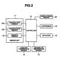
- FIG 2 is a block diagram illustrating a control system of the air conditioning system shown in Figure 1 .
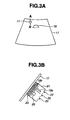
- Figure 3A is a diagram illustrating a layout of a sensor unit shown in Figure 2
- Figure 3B is a sectional view of the sensor unit along the line A-A of Figure 3A .
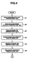
- Figure 4 is a flowchart illustrating an operation of defogging according an exemplary embodiment of the present disclosure.
- Figure 5 is a flowchart illustrating an operation to be performed after the flowchart shown in Figure 4 .
- Figure 6 is a flowchart illustrating an operation to be performed after the flowchart shown in Figure 5 .
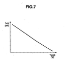
- Figure 7 is a graph illustrating a relationship between predetermined time Ts and temperature Tam of an outside ambient air which may be used in step S17 , as shown in Figure 5 .
- blower fan 2 may be rotated and an inside air (recirculated air) or an outside air (fresh air) may be sucked into air conditioning unit 3 through inside/outside air (recirculation/fresh air) switching door D1 .
- a pressurized refrigerant may be transmitted to evaporator 4 by driving compressor 12 (see Figure 2 ), and the air sucked into air conditioning unit 3 may pass through evaporator 4 to thereby be dehumidified and cooled.
- the air passing through evaporator 4 may be divided into a part thereof which may pass through heater core 5 to thereby be heated, and the remaining part thereof which may bypass heater core 5 in the cooled condition, at a ratio according to an opening of air-mix door D2.
- the part that may pass through heater core 5 and the remaining part that may bypass heater core 5 may be mixed with each other downstream from heater core 5, so that an air-conditioned wind may be generated.
- the air-conditioned wind may be blown from a vent outlet port, a defroster outlet port, or a foot outlet port which may be exposed to an inside of a passenger compartment of the vehicle, via vent door D3, defroster door D4, and foot door D5, respectively, which may be opened and closed in accordance with a plurality of air conditioning modes.
- vent door D3, defroster door D4, or foot door D5 may be opened, respectively.
- a bilevel mode vent door D3 and foot door D5 may be opened.
- defroster door D4 and foot door D5 may be opened.
- Blower fan 2 and respective doors D1 to D5 may be driven by actuator 13 (see Figure 2 ), which may be a motor.
- a windshield defroster outlet port (a front defroster) may be disposed on an upper surface of an instrument panel near a lower end portion of front windshield glass 17 along a width direction of the vehicle. Blowing of the air-conditioned wind from the windshield defroster outlet port may remove fogging of front windshield glass 17.
- a side defroster outlet port (a side defroster) may be disposed at both end portions of the instrument panel in the width direction of the vehicle and may blow the air-conditioned wind toward a door glass.
- the control system for controlling vehicular air conditioning system 1 may include sensor unit 11, compressor 12, actuator 13, coolant temperature sensor 14, outside ambient air temperature sensor 15 all in communication with controller 16, as shown in Figure 2 .
- sensor unit 11 may, preferably, be disposed in a position on an inside surface of front windshield glass 17 which may be apart from the defroster outlet ports (at a lower side of the windshield) as far as possible and may be allowed to be free from exposure to the defroster wind.
- sensor unit 11 may be mounted to a portion of front windshield glass 17 which may be in the middle in the width direction of the vehicle and near a mounting site of rearview mirror 18 at an upper end portion of front windshield glass 17.
- sensor unit 11 may include temperature sensor 19a that may detect temperature Tga of vehicle inside air in the vicinity of front windshield glass 17, temperature sensor 19b that may detect temperature Tg of an inner surface of front windshield glass 17, and humidity sensor 20 that may detect humidity RH of the vehicle inside air in the vicinity of front windshield glass 17.
- Sensor unit 11 may include additional sensors and may also be located anywhere within the passenger compartment of the vehicle. Additionally, the sensors may be located throughout the passenger compartment, but may not be in a single sensor unit 11, but may be in multiple sensor units.
- Temperature sensors 19a and 19b and humidity sensor 20 may be disposed on an inside of generally box-shaped body 21. Holes 22, which may be provided for introducing the inside air to the sensor elements, may be formed in an upper surface of box-shaped body 21. Box-shaped body 21 may have an elastic resin film 23 on a bottom surface thereof, to which temperature sensor 19b may be fixed. Temperature sensors 19a and 19b may both, preferably, be constituted of thermistors, but may also be any means of measuring temperature. Temperature sensors 19a and 19b and humidity sensor 20 may output signals to controller 16 via a harness (not shown).
- coolant temperature sensor 14 may detect engine coolant temperature Tw in the vehicle, and outside ambient air temperature sensor 15 may detect temperature Tam of ambient air outside of the vehicle.
- vehicle speed sensor 24 may detect the speed of the vehicle and may output a value indicative of the detected vehicle speed to controller 16.
- Controller 16 may perform processing, as described later, based on the signals from these sensors and may output control signals to compressor 12 and actuator 13.
- Controller 16 may include a timer or clock, a memory for storing values output from the plurality of sensors and predetermined values, and a processor to calculate rates and compare values.
- controller 16 may receive other signals necessary for air conditioning control. For example, signals from a solar radiation sensor for detecting an amount of solar radiation, an air intake temperature sensor for detecting an air intake temperature of the air after passing through evaporator 4, and a setting device for setting a target temperature in the passenger compartment. Illustrations and further discussion of these sensors and device, or any other sensors and devices, are omitted, but may be incorporated into the air conditioning system described herein.
- the thus constructed vehicular air conditioning system 1 may suppress fogging of a window glass (particularly, a door glass) due to change in the outside air temperature by performing the following defogging operation, explained by referring to the flowcharts shown in Figures 4-6 .
- the flowcharts shown in Figures 4-6 illustrate a routine of the defogging operation which may be repeatedly performed by controller 16 at predetermined intervals.
- controller 16 may detect engine coolant temperature Tw(t) through coolant temperature sensor 14.
- controller 16 may detect inner surface temperature Tg(t) of front windshield glass 17 through temperature sensor 19b.
- controller 16 may detect inside air temperature Tga(t) in the vicinity of front windshield glass 17 through temperature sensor 19a.
- controller 16 may detect relative humidity RH(t) of the inside air in the vicinity of front windshield glass 17 through humidity sensor 20.
- controller 16 may detect temperature Tam(t) of ambient air outside of the vehicle through outside air temperature sensor 15.
- variable t is a time when the process is executed. Throughout the operation of the vehicle the process may be executed n times. The operation may be executed at any time interval, for example, every 0.5 seconds.
- controller 16 may determine whether or not engine coolant temperature Tw(t) detected in step S1 may be less than predetermined temperature A. As a result of the determination, in a case where engine coolant temperature Tw(t) may be less than predetermined engine coolant temperature A, controller 16 may determine that a period of time during which the vehicle may be in the OFF state may be long and there may be a high possibility that a temperature difference between the front window glass and the door glass may be increased. The routine may then proceed to step S12 .
- controller 16 may determine that the period of time during which the vehicle may be in the OFF state may be short and there may be a low possibility that the temperature difference between the front window glass and the door glass may be increased. The routine may then proceed to step S18 . Further, if the vehicle is already in the ON state, the controller 16 may determine that Tw(t) is greater than predetermined engine coolant temperature A. In this case, the routine may proceed to step S18 .
- controller 16 may detect the engine coolant temperature in order to determine a length of the period of time during which the vehicle may be in the OFF state
- controller 16 may determine the length of the period of time during which the vehicle may be in the OFF state by using other methods such as actual measurement of the period of time during which the vehicle may be in the stopped state, which may be determined by the timer or clock of controller 16, or by an independent timer or clock.
- controller 16 may determine if the vehicle has been in the OFF state for a predetermined time. If it is greater than a predetermined time, then the routine may proceed to step S12 . However, if it is less than a predetermined time, then the routine may proceed to step S18 .
- controller 16 may determine whether or not vehicle speed V may be greater than predetermined speed B, and thereby may determine whether or not the vehicle may be started to shift from a stopped state to a moving state. At a time when vehicle speed V may become greater than predetermined speed B, controller 16 may determine that the vehicle may be started to shift from the stopped state to the moving state and proceed to step S13 .
- controller 16 may determine a rate of change in the ambient air outside of the vehicle.
- the rate may be obtained by dividing the difference between a current detected temperature value and a previous detected temperature value by a time interval between the previous detection and the current detection. Specifically, outside ambient air temperature value Tam ( n -1) of the ambient air outside of the vehicle, which may have been detected in a previous processing in step S5 , and outside ambient air temperature value Tam(n) of the ambient air outside of the vehicle, which may have been detected in a current processing in step S5 , are compared. In this calculation, n is the current processing operation. This difference is then divided by the time interval between temperature measurements. Controller 16 may then compare the rate of change of the ambient air outside the vehicle with a predetermined value C.
- controller 16 may proceed to the processing in step S14 .
- controller 16 may proceed to the processing in step S18 .
- controller 16 may determine a rate of change in the inner surface temperature of front windshield 17.
- the rate may be obtained by dividing the difference between a current detected temperature value and a previous detected temperature value by a time interval between the previous detection and the current detection. Specifically, inner surface temperature value Tg ( n -1) of front windshield glass 17, which may have been detected in a previous processing in step S2 , and inner surface temperature value Tg(n) of front windshield glass 17, which may have been detected in a current processing in step S2 , are compared. This difference is then divided by the time interval between temperature measurements. Controller 16 may then compare the rate of change of the inner surface temperature with a predetermined value D.
- controller 16 may proceed to the processing in step S15 .
- controller 16 may proceed to the processing in step S18 .
- controller 16 may set correction value ⁇ for a fogging prevention determination value to predetermined value X, where X is non-zero.
- the predetermined value X may be preset in controller 16 and may be determined based on a difference in heat resistance between front windshield glass 17 and the door glass.
- controller 16 may switch the timer of controller 16, for counting an elapsed time (count value), from the OFF state to the ON state.
- controller 16 may determine whether or not a count value T of the timer may be greater than predetermined value Ts.
- Predetermined value Ts may be a value that may be decreased with an increase in temperature Tam(t) of the ambient air outside of the vehicle and may be set and adjusted by controller 16 accordingly, as illustrated in Figure 7 .
- controller 16 may proceed to the processing in step S18 .
- S18 is processed when the time to reach predetermined time Ts may have elapsed since controller 16 set correction value ⁇ for the fogging prevention determination value to predetermined value X.
- controller 16 may proceed to the processing as detailed in Figure 6 , as detailed below.
- controller 16 may set correction value ⁇ for the fogging prevention determination value to zero. The process may then proceed to the procedure as shown in Figure 6 .
- controller 16 may compare inner surface temperature Tg(t) of front windshield glass 17, which may have been detected in step S2 , with a threshold fogging prevention determination value.
- the threshold fogging prevention determination value may be obtained by adding correction value ⁇ to dew-point temperature Td(t) calculated in step S6 .
- Controller 16 may then determine whether or not inner surface temperature Tg(t) of front windshield glass 17 may be less than the threshold fogging prevention determination value. In a case where inner surface temperature Tg(t) of front windshield glass 17 may be less than the threshold fogging prevention determination value controller 16 may proceed to the processing in step S22 . On the other hand, in a case where inner surface temperature Tg(t) of front windshield glass 17 may be greater than the threshold fogging prevention determination value controller 16 may proceed to the processing in step S24 .
- controller 16 may determine that there may be a possibility of fogging of the window glass and may set a fogging determination flag to the ON state.
- controller 16 may output a control signal to either one or both of compressor 12 and actuator 13 and may perform such an air conditioning operation as to defog the window glass (i.e., a defogging operation). Specifically, fogging on the window glass may be removed by decreasing the dew-point temperature near the inner surface of the window glass by blowing a dehumidified air across the window glass, or by increasing the outer surface temperature of the window glass by blowing out an air having a relatively high temperature across the window glass. Therefore, controller 16 may perform any one of the following operations (a)-(e) or any combination thereof, during step S23 :
- step S23 the process may return to step S17 to determine if count value T of the timer is greater than predetermined value Ts. If the count value T is still less than predetermined time Ts, then the process repeats the steps of Figure 6 . However, if the count value T is greater than predetermined time Ts, then correction value ⁇ is set to zero and the steps of Figure 6 may be completed for a final processing.
- controller 16 may proceed to the processing in step S24 . Controller 16 may determine that there may be no possibility of occurrence of fogging on the window glass, and may set the fogging determination flag to the OFF state.
- controller 16 may output control signals to compressor 12 and actuator 13 and may stop the defogging operation if the fogging determination flag was previously set to the ON state. Or, alternatively, if the defogging operation was previously set to the OFF state, the fogging determination flag may remain in the OFF state.
- controller 16 may determine whether or not temperature Tam of the outside air of the vehicle may be decreased by a value greater than the predetermined value. In a case where it may be determined that temperature Tam of the outside air of the vehicle may be decreased by a value greater than the predetermined value, controller 16 may set fogging prevention determination value Td + ⁇ so as to determine earlier that there may be a possibility of occurrence of fogging on the window glass. As a result, it may be possible to suppress fogging of the window glass with a change in temperature Tam of the outside air of the vehicle and ensure visibility.
- controller 16 may determine whether or not temperature Tam of the ambient air outside of the vehicle may be decreased by the value greater than the predetermined value when the vehicle may be started to shift from a stopped state to a running state. As a result, it may be possible to suppress occurrence of such an error that the defogging operation may be started in response to a drop in the ambient air temperature outside the vehicle which may be caused by operation of a radiator cooling fan during idling of the vehicle.
- controller 16 may set the fogging prevention determination value by adding correction value ⁇ , which may be determined on the basis of a difference in heat resistance between the front windshield glass and the door glass of the vehicle, to the determined dew-point value.
- correction value ⁇ which may be determined on the basis of a difference in heat resistance between the front windshield glass and the door glass of the vehicle.
- controller 16 may correct the fogging prevention determination value. Therefore, it may be possible to suppress an error in determination of fogging.
- controller 16 may determine whether or not the temperature of the ambient air outside of the vehicle may be decreased by the value greater than the predetermined value. Therefore, it may be possible to suppress an error in determination of fogging.
- controller 16 may reset the fogging prevention determination value to a value in the ordinary state in response to lapse of predetermined time Ts that may be set in accordance with temperature Tam of the outside air of the vehicle.
- Ts predetermined time
- the time that may be taken to achieve a convergence of the temperature difference between the front windshield glass and the door glass in the vehicle running state and a convergence of the temperature difference between the front windshield glass and the door glass in the vehicle stopped state may be increased. Therefore, due to the above defogging operation as described herein, a correction time may be appropriately set to thereby suppress erroneous determination of occurrence of fogging.
- correction value ⁇ may be subtracted from detected inner surface temperature Tg(t) instead of being added to dew-point temperature Td(t) (threshold value of fogging prevention determination). Due to such a correction, the presence of a possibility of occurrence of fogging on the window glass may be determined earlier.
- this system advantageously allows a vehicle to prevent fogging of windows prior to impairment of visibility to a driver.
- the system allows for operation during initial start-up of the vehicle, and may be effective when driving a vehicle from a garage into the open air, where a sudden temperature difference may be present, so that fogging of windows may occur.
- the present system may be effective when a driver is operating a vehicle in a tunnel, and after leaving the tunnel, there is a sudden change in the temperature so that fogging of windows may occur.
- the present system may be effective when a driver experiences a sudden change in the weather, wherein fogging of the windows may occur due to changes in the temperature or humidity conditions.
Landscapes
- Physics & Mathematics (AREA)
- Thermal Sciences (AREA)
- Engineering & Computer Science (AREA)
- Mechanical Engineering (AREA)
- Air-Conditioning For Vehicles (AREA)
Abstract
Description
- The present invention relates to an air conditioning system for a vehicle which is capable of defogging a window glass.
- Japanese Patent Application Laid-Open No.
7-232549 - In one aspect, the present disclosure relates to an air conditioning system for a vehicle, comprising a controller and a plurality of sensors in communication with the controller. The plurality of sensors include an interior temperature sensor for a vehicle interior, and an inner surface temperature sensor for a windshield. The controller is configured to determine a dew-point for the vehicle interior based on the sensed interior temperature and further configured to adjust the dew-point or the inner surface temperature based on a correction value. The controller performs a defogging operation when the inner surface temperature is less than the dew-point, wherein the dew-point or the inner surface temperature is adjusted value.
- In an embodiment, the air conditioning system of a vehicle comprises: a controller and a plurality of sensors in communication with the controller, wherein the plurality of sensors includes an interior temperature sensor for a vehicle interior, a relative humidity sensor for the vehicle interior, and an inner surface temperature sensor for a windshield. The controller is configured to determine a dew-point for the vehicle interior based on the sensed interior temperature and the sensed relative humidity. The controller is further configured to adjust the dew-point based on a correction value and is further configured to perform a defogging operation when the inner surface temperature is less than the adjusted dew-point.
- In another aspect, the present disclosure relates to an air conditioning system for a vehicle, comprising a controller and a plurality of sensors in communication with the controller. The plurality of sensors include a means for sensing a temperature of an interior of the vehicle, a means for sensing a relative humidity of the interior of the vehicle, and a means for sensing an inner surface temperature of a windshield of the vehicle. The controller is configured to determine a dew-point of the interior of the vehicle from the sensed interior temperature and the sensed relative humidity and further configured to adjust the dew-point using a means for correction. The controller performs a defogging operation when the sensed inner surface temperature is less than the adjusted dew-point.
- In an embodiment of the present disclosure, the means for correction may at least partially be based on the difference between the heat resistance of the windshield and the heat resistance of a vehicle door glass.
- In an embodiment of the present disclosure, the defogging operation may include at least one of: adjusting the vehicle interior temperature; changing an air conditioning mode to a defroster mode; increasing a rotational speed of a blower fan to increase an amount of output from a plurality of defroster vents; increasing a temperature of air blown from the plurality of defroster vents; changing an air flow configuration from recirculation to introduction of outside ambient air; and blowing dehumidified air out of the plurality of defroster vents.
- In another aspect, the present disclosure relates to a method of defogging vehicle window glass. The method comprises: determining a temperature of a vehicle interior; determining a dew-point based on the determined temperature; determining an inner surface temperature of a windshield; adjusting the dew-point or the inner surface temperature based on a correction value; comparing the inner surface temperature to the dew-point; and performing a defogging operation when the inner surface temperature is less than the dew-point, wherein the dew-point or the inner surface temperature is adjusted value.
- Features of the present disclosure will become more apparent from the following description in conjunction with the accompanying drawings.
-
Figure 1 is a schematic diagram illustrating a construction of an air conditioning system for a vehicle according to an exemplary embodiment of the present disclosure. -
Figure 2 is a block diagram illustrating a control system of the air conditioning system shown inFigure 1 . -
Figure 3A is a diagram illustrating a layout of a sensor unit shown inFigure 2 , andFigure 3B is a sectional view of the sensor unit along the line A-A ofFigure 3A . -
Figure 4 is a flowchart illustrating an operation of defogging according an exemplary embodiment of the present disclosure. -
Figure 5 is a flowchart illustrating an operation to be performed after the flowchart shown inFigure 4 . -
Figure 6 is a flowchart illustrating an operation to be performed after the flowchart shown inFigure 5 . -
Figure 7 is a graph illustrating a relationship between predetermined time Ts and temperature Tam of an outside ambient air which may be used in step S17, as shown inFigure 5 . - A construction and operation of an air conditioning system for a vehicle according to an exemplary embodiment of the present disclosure will be explained hereinafter by referring to the accompanying drawings.
- In vehicular air conditioning system 1
blower fan 2 may be rotated and an inside air (recirculated air) or an outside air (fresh air) may be sucked intoair conditioning unit 3 through inside/outside air (recirculation/fresh air) switching door D1. A pressurized refrigerant may be transmitted to evaporator 4 by driving compressor 12 (seeFigure 2 ), and the air sucked intoair conditioning unit 3 may pass through evaporator 4 to thereby be dehumidified and cooled. The air passing through evaporator 4 may be divided into a part thereof which may pass throughheater core 5 to thereby be heated, and the remaining part thereof which may bypassheater core 5 in the cooled condition, at a ratio according to an opening of air-mix door D2. The part that may pass throughheater core 5 and the remaining part that may bypassheater core 5 may be mixed with each other downstream fromheater core 5, so that an air-conditioned wind may be generated. The air-conditioned wind may be blown from a vent outlet port, a defroster outlet port, or a foot outlet port which may be exposed to an inside of a passenger compartment of the vehicle, via vent door D3, defroster door D4, and foot door D5, respectively, which may be opened and closed in accordance with a plurality of air conditioning modes. - In a vent mode, a defroster mode, and a foot mode, vent door D3, defroster door D4, or foot door D5 may be opened, respectively. In a bilevel mode, vent door D3 and foot door D5 may be opened. In a def-foot mode, defroster door D4 and foot door D5 may be opened.
Blower fan 2 and respective doors D1 to D5 may be driven by actuator 13 (seeFigure 2 ), which may be a motor. A windshield defroster outlet port (a front defroster) may be disposed on an upper surface of an instrument panel near a lower end portion offront windshield glass 17 along a width direction of the vehicle. Blowing of the air-conditioned wind from the windshield defroster outlet port may remove fogging offront windshield glass 17. Further, a side defroster outlet port (a side defroster) may be disposed at both end portions of the instrument panel in the width direction of the vehicle and may blow the air-conditioned wind toward a door glass. - The control system for controlling vehicular air conditioning system 1 may include
sensor unit 11,compressor 12,actuator 13,coolant temperature sensor 14, outside ambientair temperature sensor 15 all in communication withcontroller 16, as shown inFigure 2 . As shown inFigures 3A and 3B ,sensor unit 11 may, preferably, be disposed in a position on an inside surface offront windshield glass 17 which may be apart from the defroster outlet ports (at a lower side of the windshield) as far as possible and may be allowed to be free from exposure to the defroster wind. For example,sensor unit 11 may be mounted to a portion offront windshield glass 17 which may be in the middle in the width direction of the vehicle and near a mounting site ofrearview mirror 18 at an upper end portion offront windshield glass 17. As shown inFigure 3B ,sensor unit 11 may includetemperature sensor 19a that may detect temperature Tga of vehicle inside air in the vicinity offront windshield glass 17,temperature sensor 19b that may detect temperature Tg of an inner surface offront windshield glass 17, andhumidity sensor 20 that may detect humidity RH of the vehicle inside air in the vicinity offront windshield glass 17.Sensor unit 11 may include additional sensors and may also be located anywhere within the passenger compartment of the vehicle. Additionally, the sensors may be located throughout the passenger compartment, but may not be in asingle sensor unit 11, but may be in multiple sensor units. -
Temperature sensors humidity sensor 20 may be disposed on an inside of generally box-shaped body 21.Holes 22, which may be provided for introducing the inside air to the sensor elements, may be formed in an upper surface of box-shaped body 21. Box-shaped body 21 may have anelastic resin film 23 on a bottom surface thereof, to whichtemperature sensor 19b may be fixed.Temperature sensors Temperature sensors humidity sensor 20 may output signals to controller 16 via a harness (not shown). - Additional sensors located throughout the vehicle may also be in communication with
controller 16. For example,coolant temperature sensor 14 may detect engine coolant temperature Tw in the vehicle, and outside ambientair temperature sensor 15 may detect temperature Tam of ambient air outside of the vehicle. Additionally,vehicle speed sensor 24 may detect the speed of the vehicle and may output a value indicative of the detected vehicle speed tocontroller 16. - Signals from the plurality of sensors, including
coolant temperature sensor 14, outside ambientair temperature sensor 15,temperature sensors humidity sensor 20 may be input tocontroller 16.Controller 16 may perform processing, as described later, based on the signals from these sensors and may output control signals tocompressor 12 andactuator 13. -
Controller 16 may include a timer or clock, a memory for storing values output from the plurality of sensors and predetermined values, and a processor to calculate rates and compare values. - Further,
controller 16 may receive other signals necessary for air conditioning control. For example, signals from a solar radiation sensor for detecting an amount of solar radiation, an air intake temperature sensor for detecting an air intake temperature of the air after passing through evaporator 4, and a setting device for setting a target temperature in the passenger compartment. Illustrations and further discussion of these sensors and device, or any other sensors and devices, are omitted, but may be incorporated into the air conditioning system described herein. - The thus constructed vehicular air conditioning system 1 may suppress fogging of a window glass (particularly, a door glass) due to change in the outside air temperature by performing the following defogging operation, explained by referring to the flowcharts shown in
Figures 4-6 . The flowcharts shown inFigures 4-6 illustrate a routine of the defogging operation which may be repeatedly performed bycontroller 16 at predetermined intervals. - A description of a vehicle being first turned on is described below. However, the process as described may be continuously operated to perform the defogging operation during operation of the vehicle.
- In the flowchart shown in
Figure 4 , the routine may be started at the time (t=0) when an ignition switch of the vehicle is turned from the OFF state to the ON state (that is, at the time of start-up of the vehicle). - In step S1,
controller 16 may detect engine coolant temperature Tw(t) throughcoolant temperature sensor 14. In step S2,controller 16 may detect inner surface temperature Tg(t) offront windshield glass 17 throughtemperature sensor 19b. In step S3,controller 16 may detect inside air temperature Tga(t) in the vicinity offront windshield glass 17 throughtemperature sensor 19a. In step S4,controller 16 may detect relative humidity RH(t) of the inside air in the vicinity offront windshield glass 17 throughhumidity sensor 20. In step S5,controller 16 may detect temperature Tam(t) of ambient air outside of the vehicle through outsideair temperature sensor 15. In step S6,controller 16 may calculate dew-point temperature Td(t) in the vicinity offront windshield glass 17 by using the following mathematical expression:
- In steps S1-S6, variable t is a time when the process is executed. Throughout the operation of the vehicle the process may be executed n times. The operation may be executed at any time interval, for example, every 0.5 seconds.
- In step S11,
controller 16 may determine whether or not engine coolant temperature Tw(t) detected in step S1 may be less than predetermined temperature A. As a result of the determination, in a case where engine coolant temperature Tw(t) may be less than predetermined engine coolant temperature A,controller 16 may determine that a period of time during which the vehicle may be in the OFF state may be long and there may be a high possibility that a temperature difference between the front window glass and the door glass may be increased. The routine may then proceed to step S12. On the other hand, in a case where engine coolant temperature Tw(t) may be greater than predetermined temperature A,controller 16 may determine that the period of time during which the vehicle may be in the OFF state may be short and there may be a low possibility that the temperature difference between the front window glass and the door glass may be increased. The routine may then proceed to step S18. Further, if the vehicle is already in the ON state, thecontroller 16 may determine that Tw(t) is greater than predetermined engine coolant temperature A. In this case, the routine may proceed to step S18. - Although in this embodiment,
controller 16 may detect the engine coolant temperature in order to determine a length of the period of time during which the vehicle may be in the OFF state,controller 16 may determine the length of the period of time during which the vehicle may be in the OFF state by using other methods such as actual measurement of the period of time during which the vehicle may be in the stopped state, which may be determined by the timer or clock ofcontroller 16, or by an independent timer or clock. In this case,controller 16 may determine if the vehicle has been in the OFF state for a predetermined time. If it is greater than a predetermined time, then the routine may proceed to step S12. However, if it is less than a predetermined time, then the routine may proceed to step S18. - In step S12,
controller 16 may determine whether or not vehicle speed V may be greater than predetermined speed B, and thereby may determine whether or not the vehicle may be started to shift from a stopped state to a moving state. At a time when vehicle speed V may become greater than predetermined speed B,controller 16 may determine that the vehicle may be started to shift from the stopped state to the moving state and proceed to step S13. - In step S13,
controller 16 may determine a rate of change in the ambient air outside of the vehicle. The rate may be obtained by dividing the difference between a current detected temperature value and a previous detected temperature value by a time interval between the previous detection and the current detection. Specifically, outside ambient air temperature value Tam(n-1) of the ambient air outside of the vehicle, which may have been detected in a previous processing in step S5, and outside ambient air temperature value Tam(n) of the ambient air outside of the vehicle, which may have been detected in a current processing in step S5, are compared. In this calculation, n is the current processing operation. This difference is then divided by the time interval between temperature measurements.Controller 16 may then compare the rate of change of the ambient air outside the vehicle with a predetermined value C. As a result of the determination, in a case where the rate of change may be greater than predetermined rate C,controller 16 may proceed to the processing in step S14. On the other hand, in a case where the rate of change may be less than predetermined value C,controller 16 may proceed to the processing in step S18. - In step S14,
controller 16 may determine a rate of change in the inner surface temperature offront windshield 17. The rate may be obtained by dividing the difference between a current detected temperature value and a previous detected temperature value by a time interval between the previous detection and the current detection. Specifically, inner surface temperature value Tg(n-1) offront windshield glass 17, which may have been detected in a previous processing in step S2, and inner surface temperature value Tg(n) offront windshield glass 17, which may have been detected in a current processing in step S2, are compared. This difference is then divided by the time interval between temperature measurements.Controller 16 may then compare the rate of change of the inner surface temperature with a predetermined value D. As a result of the determination, in a case where the rate of change may be greater than predetermined value D,controller 16 may proceed to the processing in step S15. On the other hand, in a case where the rate of change may be less than predetermined value D,controller 16 may proceed to the processing in step S18. - In step S15,
controller 16 may set correction value β for a fogging prevention determination value to predetermined value X, where X is non-zero. The predetermined value X may be preset incontroller 16 and may be determined based on a difference in heat resistance betweenfront windshield glass 17 and the door glass. - Following step S15, the process may proceed to begin the process designated in
Figure 6 . Additionally, in step S16,controller 16 may switch the timer ofcontroller 16, for counting an elapsed time (count value), from the OFF state to the ON state. - In step S17,
controller 16 may determine whether or not a count value T of the timer may be greater than predetermined value Ts. Predetermined value Ts may be a value that may be decreased with an increase in temperature Tam(t) of the ambient air outside of the vehicle and may be set and adjusted bycontroller 16 accordingly, as illustrated inFigure 7 . - When count value T of the timer is greater than predetermined value Ts,
controller 16 may proceed to the processing in step S18. In other words, S18 is processed when the time to reach predetermined time Ts may have elapsed sincecontroller 16 set correction value β for the fogging prevention determination value to predetermined value X. In a case where it may be determined that predetermined time Ts may not have elapsed,controller 16 may proceed to the processing as detailed inFigure 6 , as detailed below. - In step S18,
controller 16 may set correction value β for the fogging prevention determination value to zero. The process may then proceed to the procedure as shown inFigure 6 . - In step S21,
controller 16 may compare inner surface temperature Tg(t) offront windshield glass 17, which may have been detected in step S2, with a threshold fogging prevention determination value. The threshold fogging prevention determination value may be obtained by adding correction value β to dew-point temperature Td(t) calculated in step S6.Controller 16 may then determine whether or not inner surface temperature Tg(t) offront windshield glass 17 may be less than the threshold fogging prevention determination value. In a case where inner surface temperature Tg(t) offront windshield glass 17 may be less than the threshold fogging preventiondetermination value controller 16 may proceed to the processing in step S22. On the other hand, in a case where inner surface temperature Tg(t) offront windshield glass 17 may be greater than the threshold fogging preventiondetermination value controller 16 may proceed to the processing in step S24. - In step S22,
controller 16 may determine that there may be a possibility of fogging of the window glass and may set a fogging determination flag to the ON state. - In step S23,
controller 16 may output a control signal to either one or both ofcompressor 12 andactuator 13 and may perform such an air conditioning operation as to defog the window glass (i.e., a defogging operation). Specifically, fogging on the window glass may be removed by decreasing the dew-point temperature near the inner surface of the window glass by blowing a dehumidified air across the window glass, or by increasing the outer surface temperature of the window glass by blowing out an air having a relatively high temperature across the window glass. Therefore,controller 16 may perform any one of the following operations (a)-(e) or any combination thereof, during step S23: - (a) change the air conditioning mode to the mode which allows air blowing from the defroster outlet port (i,e, defroster mode or def-foot mode);
- (b) increase an amount of the defroster output by increasing a rotational speed of
blower fan 2; - (c) increase a temperature of the air blown from the defroster outlet port by regulating the opening of the air-mix door D2;
- (d) in a case where inside air recirculation is conducted, shift from the inside air recirculation to outside (fresh) air introduction by operation of inside/outside air switching door D1; and
- (e) blow dehumidified air by turning on
compressor 12. - After step S23 is complete, the process may return to step S17 to determine if count value T of the timer is greater than predetermined value Ts. If the count value T is still less than predetermined time Ts, then the process repeats the steps of
Figure 6 . However, if the count value T is greater than predetermined time Ts, then correction value β is set to zero and the steps ofFigure 6 may be completed for a final processing. - If, however, it is determined that inner surface temperature Tg(t) of
front windshield glass 17 may be greater than the threshold fogging preventiondetermination value controller 16 may proceed to the processing in step S24.Controller 16 may determine that there may be no possibility of occurrence of fogging on the window glass, and may set the fogging determination flag to the OFF state. - In step S25,
controller 16 may output control signals tocompressor 12 andactuator 13 and may stop the defogging operation if the fogging determination flag was previously set to the ON state. Or, alternatively, if the defogging operation was previously set to the OFF state, the fogging determination flag may remain in the OFF state. - Advantageously, as may be understood from the above explanation, under the defogging operation of this disclosure,
controller 16 may determine whether or not temperature Tam of the outside air of the vehicle may be decreased by a value greater than the predetermined value. In a case where it may be determined that temperature Tam of the outside air of the vehicle may be decreased by a value greater than the predetermined value,controller 16 may set fogging prevention determination value Td + β so as to determine earlier that there may be a possibility of occurrence of fogging on the window glass. As a result, it may be possible to suppress fogging of the window glass with a change in temperature Tam of the outside air of the vehicle and ensure visibility. - Further, under the defogging operation in this exemplary embodiment,
controller 16 may determine whether or not temperature Tam of the ambient air outside of the vehicle may be decreased by the value greater than the predetermined value when the vehicle may be started to shift from a stopped state to a running state. As a result, it may be possible to suppress occurrence of such an error that the defogging operation may be started in response to a drop in the ambient air temperature outside the vehicle which may be caused by operation of a radiator cooling fan during idling of the vehicle. - Further, under the defogging operation as described herein,
controller 16 may set the fogging prevention determination value by adding correction value β, which may be determined on the basis of a difference in heat resistance between the front windshield glass and the door glass of the vehicle, to the determined dew-point value. As a result, it may be possible to suppress fogging of the door glass that may be disposed within a visibility region of the side mirror and may tend to undergo the fogging, preceding fogging of the front windshield glass. - Further, under the defogging operation as described herein, in a case where a rate of change (a rate of decrease) in inner surface temperature Tg(t) of
front windshield glass 17 may be greater than a predetermined value,controller 16 may correct the fogging prevention determination value. Therefore, it may be possible to suppress an error in determination of fogging. - Further, under the defogging operation as described herein, in a case where it may be determined that the engine coolant temperature may be less than a predetermined temperature,
controller 16 may determine whether or not the temperature of the ambient air outside of the vehicle may be decreased by the value greater than the predetermined value. Therefore, it may be possible to suppress an error in determination of fogging. - Further, under the defogging operation as described herein,
controller 16 may reset the fogging prevention determination value to a value in the ordinary state in response to lapse of predetermined time Ts that may be set in accordance with temperature Tam of the outside air of the vehicle. In general, as temperature Tam of the ambient air outside of the vehicle may become lower, the time that may be taken to achieve a convergence of the temperature difference between the front windshield glass and the door glass in the vehicle running state and a convergence of the temperature difference between the front windshield glass and the door glass in the vehicle stopped state may be increased. Therefore, due to the above defogging operation as described herein, a correction time may be appropriately set to thereby suppress erroneous determination of occurrence of fogging. - Modifications and variations of the embodiment described above may occur to those skilled in the art in light of the above disclosure. For instance, correction value β may be subtracted from detected inner surface temperature Tg(t) instead of being added to dew-point temperature Td(t) (threshold value of fogging prevention determination). Due to such a correction, the presence of a possibility of occurrence of fogging on the window glass may be determined earlier.
- Further, one skilled in the art may recognize modifications of the present operation, such as omitting the steps of determining the engine coolant temperature or the vehicle speed, without deviating from the scope of the present disclosure.
- Additionally, as noted above, this system advantageously allows a vehicle to prevent fogging of windows prior to impairment of visibility to a driver. The system allows for operation during initial start-up of the vehicle, and may be effective when driving a vehicle from a garage into the open air, where a sudden temperature difference may be present, so that fogging of windows may occur. Further, the present system may be effective when a driver is operating a vehicle in a tunnel, and after leaving the tunnel, there is a sudden change in the temperature so that fogging of windows may occur. Further, the present system may be effective when a driver experiences a sudden change in the weather, wherein fogging of the windows may occur due to changes in the temperature or humidity conditions.
- While the disclosure has been presented with respect to a limited number of embodiments, those skilled in the art, having benefit of this disclosure, will appreciate that other embodiments may be devised which do not depart from the scope of the present disclosure. Accordingly, the scope of the invention should be limited only by the attached claims.
Claims (12)
- An air conditioning system (1) of a vehicle, comprising:a controller (16); anda plurality of sensors in communication with the controller, wherein;the plurality of sensors includes an interior temperature sensor (19a) for a vehicle interior, and an inner surface temperature sensor (19b) for a windshield (17),the controller (16) is configured to determine a dew-point for the vehicle interior based on the sensed interior temperature,the controller (16) is further configured to adjust the dew-point or the inner surface temperature based on a correction value, andthe controller (16) is further configured to perform a defogging operation when the inner surface temperature is less than the dew-point, wherein the dew-point or the inner surface temperature is adjusted value.
- The air conditioning system (1) of a vehicle of claim 1, wherein the correction value is based on the difference between a heat resistance of the windshield (17) and a heat resistance of a vehicle door glass.
- The air conditioning system of a vehicle of claim 1, wherein:the plurality of sensors includes an outside temperature sensor (15) for an outside ambient air,the controller (16) is further configured to determine a rate of change of the outside temperature, andthe controller (16) is further configured to perform the adjusting the dew-point or the inner surface temperature when the determined rate of change of the outside temperature is greater than a predetermined outside temperature value.
- The air conditioning system of a vehicle of claim 1, wherein the defogging operation comprises at least one of:adjusting the vehicle interior temperature;changing an air conditioning mode to a defroster mode;increasing a rotational speed of a blower fan to increase an amount of output from a plurality of defroster vents;increasing a temperature of air blown from the plurality of defroster vents;changing an air flow configuration from recirculation to introduction of outside ambient air; andblowing dehumidified air out of the plurality of defroster vents.
- The air conditioning system of a vehicle of claim 1, wherein:the plurality of sensors includes a vehicle speed sensor (24),the controller (16) is further configured to determine if the vehicle is in a stopped state or a moving state based on the vehicle speed, andthe controller (16) is further configured to determine whether the inner surface temperature is less than the adjusted dew-point when the vehicle is shifted from the stopped state to the moving state.
- The air conditioning system of a vehicle of claim 1, wherein:the controller (16) is further configured to determine a rate of change of the interior temperature, andthe controller (16) is further configured to adjust the correction value when the determined rate of change of the vehicle interior temperature is greater than a predetermined vehicle interior value.
- The air conditioning system of a vehicle of claim 1, wherein:the plurality of sensors includes an engine coolant temperature sensor (14), andthe controller (16) is further configured to determine whether the inner surface temperature is less than the adjusted dew-point when the sensed engine coolant temperature is less than a predetermined engine coolant value.
- The air conditioning system of a vehicle of claim 1, wherein:the controller (16) is further configured to count time, andthe controller (16) stops adjusting the dew-point when a predetermined time has elapsed.
- The air conditioning system of a vehicle of claim 8, wherein the controller (16) decreases the predetermined time as the outside ambient air temperature increases.
- A method to defog vehicle window glass, the method comprising:determining a temperature of a vehicle interior;determining a dew-point based on the determined temperature of the vehicle interior;determining an inner surface temperature of a windshield (17);adjusting the dew-point or the inner surface temperature based on a correction value;comparing the inner surface temperature to the dew-point; andperforming a defogging operation when the inner surface temperature is less than the dew-point, wherein the dew-point or the inner surface temperature is adjusted value.
- The method to defog vehicle window glass of claim 10, wherein the correction value is based at least partially on a difference between a heat resistance of the windshield (16) and a heat resistance of a vehicle door glass.
- The method to defog vehicle window glass of claim 10, wherein the defogging operation comprises at least one of:adjusting the temperature of the vehicle interior;changing an air conditioning mode to a defroster mode;increasing a rotational speed of a blower fan to increase an amount of output from a plurality of defroster vents;increasing a temperature of air blown from the plurality of defroster vents;changing an air flow configuration from recirculation to introduction of outside ambient air; andblowing dehumidified air out of the plurality of defroster vents.
Applications Claiming Priority (2)
| Application Number | Priority Date | Filing Date | Title |
|---|---|---|---|
| JP2008332757 | 2008-12-26 | ||
| JP2009143365A JP4962530B2 (en) | 2008-12-26 | 2009-06-16 | Air conditioner for vehicles |
Publications (2)
| Publication Number | Publication Date |
|---|---|
| EP2202107A1 true EP2202107A1 (en) | 2010-06-30 |
| EP2202107B1 EP2202107B1 (en) | 2011-07-20 |
Family
ID=42026343
Family Applications (1)
| Application Number | Title | Priority Date | Filing Date |
|---|---|---|---|
| EP09180436A Active EP2202107B1 (en) | 2008-12-26 | 2009-12-22 | Air conditioning system for vehicle |
Country Status (5)
| Country | Link |
|---|---|
| US (1) | US8733428B2 (en) |
| EP (1) | EP2202107B1 (en) |
| JP (1) | JP4962530B2 (en) |
| CN (1) | CN101863211B (en) |
| AT (1) | ATE516976T1 (en) |
Cited By (7)
| Publication number | Priority date | Publication date | Assignee | Title |
|---|---|---|---|---|
| DE102011084278A1 (en) | 2011-10-11 | 2013-04-11 | Ford Global Technologies, Llc | Method for preventing fogging of window panes of motor car, involves activating anti-fogging operation if time variation of measurement values of air humidity sensor or time variation of dew point temperature is larger than threshold level |
| CN103318140A (en) * | 2013-05-28 | 2013-09-25 | 奇瑞汽车股份有限公司 | Automatic demisting system for front windshield inner surface of automobile |
| CN103707890A (en) * | 2012-10-03 | 2014-04-09 | 通用汽车环球科技运作有限责任公司 | Temperature sensor rationalization |
| CN103963597A (en) * | 2013-01-31 | 2014-08-06 | 杭州三花研究院有限公司 | Automatic automobile air conditioner controller |
| EP3034338A1 (en) * | 2014-12-17 | 2016-06-22 | The Boeing Company | Automatic activation of a fog protection system onboard a vehicle |
| US9724980B2 (en) | 2014-08-20 | 2017-08-08 | Ford Global Technologies, Llc | Windshield defogging system and method |
| EP4219198A4 (en) * | 2020-10-31 | 2023-12-20 | Huawei Technologies Co., Ltd. | Automobile air conditioning unit, method for controlling automobile air conditioning unit, and air conditioning controller |
Families Citing this family (48)
| Publication number | Priority date | Publication date | Assignee | Title |
|---|---|---|---|---|
| US20100197406A1 (en) * | 2009-02-05 | 2010-08-05 | Ford Motor Company | System and method for vehicular ad-hoc gaming networking |
| US20110045842A1 (en) * | 2009-08-20 | 2011-02-24 | Ford Global Technologies, Llc | Method and System For Updating A Social Networking System Based On Vehicle Events |
| JP5038451B2 (en) * | 2010-03-23 | 2012-10-03 | エンパイア テクノロジー ディベロップメント エルエルシー | Control system, control method, automobile |
| JP5569425B2 (en) * | 2010-05-20 | 2014-08-13 | 株式会社デンソー | Air conditioner for vehicles |
| DE102010038682B4 (en) * | 2010-07-30 | 2022-04-28 | Bayerische Motoren Werke Aktiengesellschaft | Method for controlling a heating and air conditioning system in a vehicle |
| JP5640536B2 (en) * | 2010-08-05 | 2014-12-17 | 日産自動車株式会社 | Air conditioner for vehicles |
| US20130183894A1 (en) * | 2010-09-09 | 2013-07-18 | Takumasa Watanabe | Anti-fogging and air-conditioning system for electric vehicle, dehumidifying unit, dehumidifying cassette, and dehumidifying member |
| US8560202B2 (en) * | 2010-11-01 | 2013-10-15 | Ford Global Technologies, Llc | Method and apparatus for improved climate control function in a vehicle employing engine stop/start technology |
| US9451030B2 (en) * | 2011-02-18 | 2016-09-20 | Ford Global Technologies, Llc | Crowdsourced weather data collection and provision |
| US9447765B2 (en) | 2011-07-11 | 2016-09-20 | Ford Global Technologies, Llc | Powertrain delta current estimation method |
| US10480477B2 (en) | 2011-07-11 | 2019-11-19 | Ford Global Technologies, Llc | Electric current based engine auto stop inhibit algorithm and system implementing same |
| JP5494595B2 (en) * | 2011-09-14 | 2014-05-14 | 株式会社デンソー | Air conditioner for vehicles |
| JP2013159228A (en) * | 2012-02-06 | 2013-08-19 | Denso Corp | Vehicle air conditioner |
| US9796359B2 (en) * | 2012-02-23 | 2017-10-24 | The Raymond Corporation | Method and apparatus for removing and preventing lens surface contamination on a vehicle lens |
| US9303613B2 (en) | 2012-02-24 | 2016-04-05 | Ford Global Technologies, Llc | Control of vehicle electrical loads during engine auto stop event |
| CN103359072A (en) * | 2012-03-31 | 2013-10-23 | 杭州三花研究院有限公司 | Air conditioning system and air conditioning method for automobile |
| US20140004782A1 (en) * | 2012-06-29 | 2014-01-02 | Ford Global Technologies, Llc | System and method of controlling ventilation of a passenger compartment of a vehicle |
| US8893517B2 (en) * | 2012-08-27 | 2014-11-25 | Ford Global Technologies, Llc | Vehicle air handling system |
| US8892291B2 (en) | 2013-03-12 | 2014-11-18 | Ford Global Technologies, Llc | Vehicle mass detection system |
| CN104070959B (en) * | 2013-03-28 | 2017-10-24 | 浙江三花汽车零部件有限公司 | Obtain the method and its control system of environment temperature |
| JP6083329B2 (en) * | 2013-06-18 | 2017-02-22 | マツダ株式会社 | Air conditioning control device for vehicles |
| CN103386874B (en) * | 2013-08-02 | 2015-06-17 | 苏州贝昂科技有限公司 | Device and method for controlling vehicle-mounted air cleaner |
| US9248824B2 (en) | 2014-01-24 | 2016-02-02 | Ford Global Technologies, Llc | Rear defrost control in stop/start vehicle |
| CN103847463B (en) * | 2014-03-26 | 2016-02-10 | 惠州华阳通用电子有限公司 | A kind of control method automatically preventing automobile from hazing |
| CN104527372A (en) * | 2015-01-16 | 2015-04-22 | 北京汽车研究总院有限公司 | Automatic defogging system for automobile air-conditioner and automobile |
| FR3035177B1 (en) * | 2015-04-16 | 2022-10-07 | Valeo Vision | CONTROL DEVICE FOR A VEHICLE LIGHTING AND/OR SIGNALING SYSTEM |
| US9975401B2 (en) * | 2015-06-12 | 2018-05-22 | Ford Global Technologies, Llc | Method and apparatus for avoiding windowpane misting in a vehicle |
| US9975400B2 (en) * | 2015-06-18 | 2018-05-22 | Ford Global Technologies, Llc | Method of controlling climate in a parked vehicle |
| CN106476562A (en) * | 2015-08-31 | 2017-03-08 | 株式会社电装 | Air conditioner for vehicles and Vehicular air conditioner control device |
| US20170106721A1 (en) * | 2015-10-15 | 2017-04-20 | Ford Global Technologies, Llc | Energy-efficient vehicle window defogging and prevention of re-freezing |
| CN105346355B (en) * | 2015-11-16 | 2017-12-05 | 兵器工业卫生研究所 | Land equipment cabin microenvironment integral control system |
| US10293657B2 (en) | 2016-02-25 | 2019-05-21 | Toyota Motor Engineering & Manufacturing North America, Inc. | Vehicle automatic defrost system and method |
| US10246073B2 (en) | 2016-05-16 | 2019-04-02 | Ford Global Technologies, Llc | Control system for a hybrid-electric vehicle |
| US10196994B2 (en) | 2016-05-16 | 2019-02-05 | Ford Global Technologies, Llc | Powertrain control system |
| US10759255B2 (en) * | 2016-07-20 | 2020-09-01 | Ford Global Technologies, Llc | Autonomous-vehicle climate-control system |
| US20190098705A1 (en) * | 2017-09-25 | 2019-03-28 | Ford Global Technologies, Llc | Windshield defrost |
| US11161455B2 (en) * | 2017-11-30 | 2021-11-02 | Ford Global Technologies, Llc | Defrost/defog system side mirror with peltier element |
| US10737551B2 (en) | 2017-11-30 | 2020-08-11 | Nissan North America, Inc. | Vehicle air handling system |
| JP2019099045A (en) * | 2017-12-06 | 2019-06-24 | 株式会社日本クライメイトシステムズ | Vehicle air conditioning device |
| US10752215B2 (en) * | 2018-05-23 | 2020-08-25 | Ford Global Technologies, Llc | Vehicle automatic defrost system and control method for external window surface |
| JP7066645B2 (en) * | 2019-01-23 | 2022-05-13 | 本田技研工業株式会社 | Control device for mobile objects |
| JP7066650B2 (en) * | 2019-03-05 | 2022-05-13 | 本田技研工業株式会社 | Anti-fog device and its control method |
| WO2020189353A1 (en) * | 2019-03-15 | 2020-09-24 | Agc株式会社 | Window glass system and window glass |
| US11052725B2 (en) * | 2019-09-26 | 2021-07-06 | Ford Global Technologies, Llc | Automatic windshield defrosting system |
| CN111497555B (en) * | 2020-04-24 | 2022-05-17 | 重庆长安汽车股份有限公司 | Heating method for automobile air conditioner |
| CN112158166B (en) * | 2020-09-30 | 2023-03-28 | 重庆长安汽车股份有限公司 | Control method for automatic demisting of automobile and automobile |
| CN114590228A (en) * | 2020-12-04 | 2022-06-07 | 纬湃汽车电子(长春)有限公司 | Method for operating a vehicle-mounted air conditioning system of a motor vehicle and defogging system |
| CN114274736B (en) * | 2022-02-16 | 2023-11-21 | 一汽解放汽车有限公司 | Anti-fog control method, device, equipment and storage medium for automobile air conditioner |
Citations (4)
| Publication number | Priority date | Publication date | Assignee | Title |
|---|---|---|---|---|
| JPS63180514A (en) * | 1987-01-21 | 1988-07-25 | Hitachi Ltd | Air conditioner for vehicle |
| JPH07232549A (en) | 1994-02-25 | 1995-09-05 | Nippondenso Co Ltd | Air conditioner for vehicle |
| DE102004045839B3 (en) * | 2004-09-22 | 2006-02-23 | Sitronic Gesellschaft für elektrotechnische Ausrüstung mbH. & Co. KG | Method of determining dispersal time point of especially motor vehicle windscreen condensation entails determining time change of water quantity on windscreen as function of windscreen and dew point temperatures |
| US20060289458A1 (en) | 2005-05-17 | 2006-12-28 | Halla Climate Control Corporation | Fogging detecting system for an automotive vehicle and method for controlling the system |
Family Cites Families (30)
| Publication number | Priority date | Publication date | Assignee | Title |
|---|---|---|---|---|
| JPS5948169B2 (en) * | 1978-10-02 | 1984-11-24 | 株式会社デンソー | Vehicle air conditioning control method and device |
| US4744511A (en) * | 1985-11-27 | 1988-05-17 | Nippondenso Co., Ltd. | Air conditioner for automobiles |
| DE10320340A1 (en) * | 2003-05-07 | 2004-12-09 | J. Eberspächer GmbH & Co. KG | Heating system for a vehicle |
| US5511724A (en) * | 1994-11-23 | 1996-04-30 | Delco Electronics Corporation | Adaptive climate control system |
| JP3334410B2 (en) * | 1995-03-14 | 2002-10-15 | 株式会社デンソー | Vehicle air conditioner |
| JP2001334820A (en) * | 2000-05-29 | 2001-12-04 | Denso Corp | Vehicle air conditioner |
| US6422062B1 (en) * | 2000-08-29 | 2002-07-23 | Delphi Technologies, Inc. | Integrated glass fog sensor unit |
| JP2002370521A (en) * | 2001-06-15 | 2002-12-24 | Denso Corp | Air-conditioner for vehicle |
| DE10153000C1 (en) * | 2001-10-26 | 2003-04-30 | Preh Elektro Feinmechanik | Process for avoiding fogging on windows of a motor vehicle |
| DE10257587B3 (en) * | 2002-12-09 | 2004-04-15 | Daimlerchrysler Ag | Climate-control regulation method for automobile with opening roof switches between different regulation modes dependent on open or closed position of opening roof |
| JP2005059797A (en) * | 2003-08-19 | 2005-03-10 | Denso Corp | Air-conditioner for vehicle |
| JP4314933B2 (en) * | 2003-08-27 | 2009-08-19 | 株式会社デンソー | Air conditioner for vehicles |
| JP2005186919A (en) * | 2003-12-04 | 2005-07-14 | Keihin Corp | Vehicular air-conditioner |
| US7197927B2 (en) * | 2004-02-16 | 2007-04-03 | Sitronic Gesellschaft für Elektrotechnische Ausrustüng mbH & Co. KG | Sensor for determining the interior humidity and fogging up tendency and fastening device of the sensor |
| US7392838B2 (en) * | 2004-06-30 | 2008-07-01 | Honda Motor Co., Ltd. | System and method for vehicle defogging condition calculation and control |
| ATE441545T1 (en) * | 2004-09-15 | 2009-09-15 | Magna Donnelly Engineering Gmb | CLIMATE CONTROL SYSTEM FOR A VEHICLE |
| JP4534973B2 (en) * | 2005-11-29 | 2010-09-01 | 株式会社デンソー | Window fogging detector |
| JP2006335117A (en) * | 2005-05-31 | 2006-12-14 | Denso Corp | Air conditioner for vehicle |
| KR100815298B1 (en) * | 2005-12-13 | 2008-03-19 | 현대자동차주식회사 | An auto defog system of vehicle and method for controlling it |
| US7832223B2 (en) * | 2006-01-10 | 2010-11-16 | Cnh America Llc | Controller area network based climate control system for a self-propelled work machine and method of operation of the same |
| JP4736872B2 (en) * | 2006-03-10 | 2011-07-27 | 株式会社デンソー | Air conditioner |
| JP2007253886A (en) * | 2006-03-24 | 2007-10-04 | Denso Corp | Air conditioner for vehicle |
| JP4816212B2 (en) * | 2006-04-10 | 2011-11-16 | 日産自動車株式会社 | Glass temperature detection device, window fogging detection device, vehicle air conditioner, and window fogging detection method |
| JP5012193B2 (en) * | 2006-06-06 | 2012-08-29 | 株式会社デンソー | Air conditioner for vehicles |
| CN200946884Y (en) * | 2006-07-06 | 2007-09-12 | 湖北美标汽车制冷系统有限公司 | Automatic controller of lorry air-conditioning system |
| EP1700724B1 (en) * | 2006-07-19 | 2009-09-02 | Sensirion Holding AG | Humidity detector for detecting fogging on a window |
| JP4858305B2 (en) * | 2006-09-15 | 2012-01-18 | 株式会社デンソー | Humidity detection device and vehicle air conditioner |
| US7696710B2 (en) * | 2006-10-30 | 2010-04-13 | Agc Automotive Americas R&D, Inc. | Method of sensing an amount of moisture on a surface of a substrate with temperature compensation |
| FR2912688B1 (en) * | 2007-02-16 | 2009-08-28 | Renault Soc Par Actions Simpli | METHOD FOR CONTROLLING THERMAL COMFORT FOR A STOP VEHICLE AND STARTING THE ENGINE |
| JP2011246083A (en) * | 2010-05-31 | 2011-12-08 | Suzuki Motor Corp | Vehicle air-conditioning device |
-
2009
- 2009-06-16 JP JP2009143365A patent/JP4962530B2/en active Active
- 2009-12-22 AT AT09180436T patent/ATE516976T1/en not_active IP Right Cessation
- 2009-12-22 EP EP09180436A patent/EP2202107B1/en active Active
- 2009-12-23 US US12/646,663 patent/US8733428B2/en active Active
- 2009-12-25 CN CN2009102470509A patent/CN101863211B/en active Active
Patent Citations (4)
| Publication number | Priority date | Publication date | Assignee | Title |
|---|---|---|---|---|
| JPS63180514A (en) * | 1987-01-21 | 1988-07-25 | Hitachi Ltd | Air conditioner for vehicle |
| JPH07232549A (en) | 1994-02-25 | 1995-09-05 | Nippondenso Co Ltd | Air conditioner for vehicle |
| DE102004045839B3 (en) * | 2004-09-22 | 2006-02-23 | Sitronic Gesellschaft für elektrotechnische Ausrüstung mbH. & Co. KG | Method of determining dispersal time point of especially motor vehicle windscreen condensation entails determining time change of water quantity on windscreen as function of windscreen and dew point temperatures |
| US20060289458A1 (en) | 2005-05-17 | 2006-12-28 | Halla Climate Control Corporation | Fogging detecting system for an automotive vehicle and method for controlling the system |
Cited By (11)
| Publication number | Priority date | Publication date | Assignee | Title |
|---|---|---|---|---|
| DE102011084278A1 (en) | 2011-10-11 | 2013-04-11 | Ford Global Technologies, Llc | Method for preventing fogging of window panes of motor car, involves activating anti-fogging operation if time variation of measurement values of air humidity sensor or time variation of dew point temperature is larger than threshold level |
| DE102011084278B4 (en) | 2011-10-11 | 2022-12-22 | Ford Global Technologies, Llc | Method and device for preventing vehicle windows from fogging up |
| CN103707890A (en) * | 2012-10-03 | 2014-04-09 | 通用汽车环球科技运作有限责任公司 | Temperature sensor rationalization |
| CN103963597A (en) * | 2013-01-31 | 2014-08-06 | 杭州三花研究院有限公司 | Automatic automobile air conditioner controller |
| CN103318140A (en) * | 2013-05-28 | 2013-09-25 | 奇瑞汽车股份有限公司 | Automatic demisting system for front windshield inner surface of automobile |
| CN103318140B (en) * | 2013-05-28 | 2016-01-27 | 奇瑞汽车股份有限公司 | A kind of front windshield inner surface of automobile automatic defrosting system |
| US9724980B2 (en) | 2014-08-20 | 2017-08-08 | Ford Global Technologies, Llc | Windshield defogging system and method |
| EP3034338A1 (en) * | 2014-12-17 | 2016-06-22 | The Boeing Company | Automatic activation of a fog protection system onboard a vehicle |
| CN105711548A (en) * | 2014-12-17 | 2016-06-29 | 波音公司 | Automatic activation of a fog protection system onboard a vehicle |
| US9834310B2 (en) | 2014-12-17 | 2017-12-05 | The Boeing Company | Automatic activation of a fog protection system onboard a vehicle |
| EP4219198A4 (en) * | 2020-10-31 | 2023-12-20 | Huawei Technologies Co., Ltd. | Automobile air conditioning unit, method for controlling automobile air conditioning unit, and air conditioning controller |
Also Published As
| Publication number | Publication date |
|---|---|
| EP2202107B1 (en) | 2011-07-20 |
| CN101863211B (en) | 2013-03-13 |
| CN101863211A (en) | 2010-10-20 |
| ATE516976T1 (en) | 2011-08-15 |
| US20100163220A1 (en) | 2010-07-01 |
| JP4962530B2 (en) | 2012-06-27 |
| US8733428B2 (en) | 2014-05-27 |
| JP2010168026A (en) | 2010-08-05 |
Similar Documents
| Publication | Publication Date | Title |
|---|---|---|
| EP2202107B1 (en) | Air conditioning system for vehicle | |
| EP1844964B1 (en) | Glas temperature detecting system, window fog detecting system, air-conditioning system for vehicles, and window fog detecting method | |
| JP4311270B2 (en) | Air conditioner for vehicles | |
| US20040103675A1 (en) | Vehicle air conditioner | |
| JPH1134637A (en) | Air conditioner for vehicle | |
| JP4310902B2 (en) | Air conditioner for vehicles | |
| JP4353053B2 (en) | Air conditioner for vehicles | |
| JP2002137630A (en) | Auto air conditioner control device for vehicle | |
| JP4706774B2 (en) | Air conditioner for vehicles | |
| KR101427231B1 (en) | Defogging device of air conditioning system for automotive vehicles | |
| KR20160013310A (en) | Air conditioning system for automotive vehicles | |
| JP2003182351A (en) | Air conditioner for vehicle | |
| JP3890963B2 (en) | Anti-fog device for vehicles | |
| JP3169063B2 (en) | Vehicle air conditioner | |
| JP3861805B2 (en) | Air conditioner for vehicles | |
| KR101645184B1 (en) | Air conditioning system for automotive vehicles | |
| JP2006056450A (en) | Inside/outside air switching device for vehicle | |
| JP2009248608A (en) | Air conditioning system for vehicle | |
| JP2006151098A (en) | Air conditioner for vehicle | |
| JP2005324638A (en) | Vehicular air-conditioner | |
| JP2005335526A (en) | Air conditioner for vehicle | |
| JP3922158B2 (en) | Air conditioner for vehicles | |
| JP3533723B2 (en) | Vehicle air conditioner | |
| JP2004255898A (en) | Air-conditioner for vehicle, and its controlling program | |
| JP2006281904A (en) | Air-conditioner for vehicle |
Legal Events
| Date | Code | Title | Description |
|---|---|---|---|
| PUAI | Public reference made under article 153(3) epc to a published international application that has entered the european phase |
Free format text: ORIGINAL CODE: 0009012 |
|
| AK | Designated contracting states |
Kind code of ref document: A1 Designated state(s): AT BE BG CH CY CZ DE DK EE ES FI FR GB GR HR HU IE IS IT LI LT LU LV MC MK MT NL NO PL PT RO SE SI SK SM TR |
|
| AX | Request for extension of the european patent |
Extension state: AL BA RS |
|
| GRAP | Despatch of communication of intention to grant a patent |
Free format text: ORIGINAL CODE: EPIDOSNIGR1 |
|
| 17P | Request for examination filed |
Effective date: 20101230 |
|
| RIC1 | Information provided on ipc code assigned before grant |
Ipc: B60S 1/54 20060101ALI20110202BHEP Ipc: B60H 1/00 20060101AFI20110202BHEP |
|
| GRAS | Grant fee paid |
Free format text: ORIGINAL CODE: EPIDOSNIGR3 |
|
| GRAA | (expected) grant |
Free format text: ORIGINAL CODE: 0009210 |
|
| AK | Designated contracting states |
Kind code of ref document: B1 Designated state(s): AT BE BG CH CY CZ DE DK EE ES FI FR GB GR HR HU IE IS IT LI LT LU LV MC MK MT NL NO PL PT RO SE SI SK SM TR |
|
| REG | Reference to a national code |
Ref country code: GB Ref legal event code: FG4D |
|
| REG | Reference to a national code |
Ref country code: CH Ref legal event code: EP |
|
| REG | Reference to a national code |
Ref country code: DE Ref legal event code: R096 Ref document number: 602009001877 Country of ref document: DE Effective date: 20110915 |
|
| REG | Reference to a national code |
Ref country code: NL Ref legal event code: VDEP Effective date: 20110720 |
|
| REG | Reference to a national code |
Ref country code: AT Ref legal event code: MK05 Ref document number: 516976 Country of ref document: AT Kind code of ref document: T Effective date: 20110720 |
|
| PG25 | Lapsed in a contracting state [announced via postgrant information from national office to epo] |
Ref country code: IS Free format text: LAPSE BECAUSE OF FAILURE TO SUBMIT A TRANSLATION OF THE DESCRIPTION OR TO PAY THE FEE WITHIN THE PRESCRIBED TIME-LIMIT Effective date: 20111120 Ref country code: HR Free format text: LAPSE BECAUSE OF FAILURE TO SUBMIT A TRANSLATION OF THE DESCRIPTION OR TO PAY THE FEE WITHIN THE PRESCRIBED TIME-LIMIT Effective date: 20110720 Ref country code: BE Free format text: LAPSE BECAUSE OF FAILURE TO SUBMIT A TRANSLATION OF THE DESCRIPTION OR TO PAY THE FEE WITHIN THE PRESCRIBED TIME-LIMIT Effective date: 20110720 Ref country code: NO Free format text: LAPSE BECAUSE OF FAILURE TO SUBMIT A TRANSLATION OF THE DESCRIPTION OR TO PAY THE FEE WITHIN THE PRESCRIBED TIME-LIMIT Effective date: 20111020 Ref country code: LT Free format text: LAPSE BECAUSE OF FAILURE TO SUBMIT A TRANSLATION OF THE DESCRIPTION OR TO PAY THE FEE WITHIN THE PRESCRIBED TIME-LIMIT Effective date: 20110720 Ref country code: SE Free format text: LAPSE BECAUSE OF FAILURE TO SUBMIT A TRANSLATION OF THE DESCRIPTION OR TO PAY THE FEE WITHIN THE PRESCRIBED TIME-LIMIT Effective date: 20110720 Ref country code: NL Free format text: LAPSE BECAUSE OF FAILURE TO SUBMIT A TRANSLATION OF THE DESCRIPTION OR TO PAY THE FEE WITHIN THE PRESCRIBED TIME-LIMIT Effective date: 20110720 Ref country code: PT Free format text: LAPSE BECAUSE OF FAILURE TO SUBMIT A TRANSLATION OF THE DESCRIPTION OR TO PAY THE FEE WITHIN THE PRESCRIBED TIME-LIMIT Effective date: 20111121 Ref country code: FI Free format text: LAPSE BECAUSE OF FAILURE TO SUBMIT A TRANSLATION OF THE DESCRIPTION OR TO PAY THE FEE WITHIN THE PRESCRIBED TIME-LIMIT Effective date: 20110720 |
|
| PG25 | Lapsed in a contracting state [announced via postgrant information from national office to epo] |
Ref country code: CY Free format text: LAPSE BECAUSE OF FAILURE TO SUBMIT A TRANSLATION OF THE DESCRIPTION OR TO PAY THE FEE WITHIN THE PRESCRIBED TIME-LIMIT Effective date: 20110720 Ref country code: PL Free format text: LAPSE BECAUSE OF FAILURE TO SUBMIT A TRANSLATION OF THE DESCRIPTION OR TO PAY THE FEE WITHIN THE PRESCRIBED TIME-LIMIT Effective date: 20110720 Ref country code: GR Free format text: LAPSE BECAUSE OF FAILURE TO SUBMIT A TRANSLATION OF THE DESCRIPTION OR TO PAY THE FEE WITHIN THE PRESCRIBED TIME-LIMIT Effective date: 20111021 Ref country code: SI Free format text: LAPSE BECAUSE OF FAILURE TO SUBMIT A TRANSLATION OF THE DESCRIPTION OR TO PAY THE FEE WITHIN THE PRESCRIBED TIME-LIMIT Effective date: 20110720 Ref country code: LV Free format text: LAPSE BECAUSE OF FAILURE TO SUBMIT A TRANSLATION OF THE DESCRIPTION OR TO PAY THE FEE WITHIN THE PRESCRIBED TIME-LIMIT Effective date: 20110720 Ref country code: AT Free format text: LAPSE BECAUSE OF FAILURE TO SUBMIT A TRANSLATION OF THE DESCRIPTION OR TO PAY THE FEE WITHIN THE PRESCRIBED TIME-LIMIT Effective date: 20110720 |
|
| PG25 | Lapsed in a contracting state [announced via postgrant information from national office to epo] |
Ref country code: SK Free format text: LAPSE BECAUSE OF FAILURE TO SUBMIT A TRANSLATION OF THE DESCRIPTION OR TO PAY THE FEE WITHIN THE PRESCRIBED TIME-LIMIT Effective date: 20110720 Ref country code: CZ Free format text: LAPSE BECAUSE OF FAILURE TO SUBMIT A TRANSLATION OF THE DESCRIPTION OR TO PAY THE FEE WITHIN THE PRESCRIBED TIME-LIMIT Effective date: 20110720 |
|
| PLBE | No opposition filed within time limit |
Free format text: ORIGINAL CODE: 0009261 |
|
| STAA | Information on the status of an ep patent application or granted ep patent |
Free format text: STATUS: NO OPPOSITION FILED WITHIN TIME LIMIT |
|
| PG25 | Lapsed in a contracting state [announced via postgrant information from national office to epo] |
Ref country code: RO Free format text: LAPSE BECAUSE OF FAILURE TO SUBMIT A TRANSLATION OF THE DESCRIPTION OR TO PAY THE FEE WITHIN THE PRESCRIBED TIME-LIMIT Effective date: 20110720 Ref country code: IT Free format text: LAPSE BECAUSE OF FAILURE TO SUBMIT A TRANSLATION OF THE DESCRIPTION OR TO PAY THE FEE WITHIN THE PRESCRIBED TIME-LIMIT Effective date: 20110720 Ref country code: EE Free format text: LAPSE BECAUSE OF FAILURE TO SUBMIT A TRANSLATION OF THE DESCRIPTION OR TO PAY THE FEE WITHIN THE PRESCRIBED TIME-LIMIT Effective date: 20110720 |
|
| 26N | No opposition filed |
Effective date: 20120423 |
|
| PG25 | Lapsed in a contracting state [announced via postgrant information from national office to epo] |
Ref country code: DK Free format text: LAPSE BECAUSE OF FAILURE TO SUBMIT A TRANSLATION OF THE DESCRIPTION OR TO PAY THE FEE WITHIN THE PRESCRIBED TIME-LIMIT Effective date: 20110720 |
|
| PG25 | Lapsed in a contracting state [announced via postgrant information from national office to epo] |
Ref country code: MC Free format text: LAPSE BECAUSE OF NON-PAYMENT OF DUE FEES Effective date: 20111231 |
|
| REG | Reference to a national code |
Ref country code: DE Ref legal event code: R097 Ref document number: 602009001877 Country of ref document: DE Effective date: 20120423 |
|
| REG | Reference to a national code |
Ref country code: IE Ref legal event code: MM4A |
|
| PG25 | Lapsed in a contracting state [announced via postgrant information from national office to epo] |
Ref country code: IE Free format text: LAPSE BECAUSE OF NON-PAYMENT OF DUE FEES Effective date: 20111222 |
|
| PG25 | Lapsed in a contracting state [announced via postgrant information from national office to epo] |
Ref country code: MK Free format text: LAPSE BECAUSE OF FAILURE TO SUBMIT A TRANSLATION OF THE DESCRIPTION OR TO PAY THE FEE WITHIN THE PRESCRIBED TIME-LIMIT Effective date: 20110720 Ref country code: MT Free format text: LAPSE BECAUSE OF FAILURE TO SUBMIT A TRANSLATION OF THE DESCRIPTION OR TO PAY THE FEE WITHIN THE PRESCRIBED TIME-LIMIT Effective date: 20110720 |
|
| PG25 | Lapsed in a contracting state [announced via postgrant information from national office to epo] |
Ref country code: SM Free format text: LAPSE BECAUSE OF FAILURE TO SUBMIT A TRANSLATION OF THE DESCRIPTION OR TO PAY THE FEE WITHIN THE PRESCRIBED TIME-LIMIT Effective date: 20110720 Ref country code: ES Free format text: LAPSE BECAUSE OF FAILURE TO SUBMIT A TRANSLATION OF THE DESCRIPTION OR TO PAY THE FEE WITHIN THE PRESCRIBED TIME-LIMIT Effective date: 20111031 |
|
| PG25 | Lapsed in a contracting state [announced via postgrant information from national office to epo] |
Ref country code: LU Free format text: LAPSE BECAUSE OF NON-PAYMENT OF DUE FEES Effective date: 20111222 |
|
| PG25 | Lapsed in a contracting state [announced via postgrant information from national office to epo] |
Ref country code: BG Free format text: LAPSE BECAUSE OF FAILURE TO SUBMIT A TRANSLATION OF THE DESCRIPTION OR TO PAY THE FEE WITHIN THE PRESCRIBED TIME-LIMIT Effective date: 20111020 |
|
| PG25 | Lapsed in a contracting state [announced via postgrant information from national office to epo] |
Ref country code: TR Free format text: LAPSE BECAUSE OF FAILURE TO SUBMIT A TRANSLATION OF THE DESCRIPTION OR TO PAY THE FEE WITHIN THE PRESCRIBED TIME-LIMIT Effective date: 20110720 |
|
| PG25 | Lapsed in a contracting state [announced via postgrant information from national office to epo] |
Ref country code: HU Free format text: LAPSE BECAUSE OF FAILURE TO SUBMIT A TRANSLATION OF THE DESCRIPTION OR TO PAY THE FEE WITHIN THE PRESCRIBED TIME-LIMIT Effective date: 20110720 |
|
| REG | Reference to a national code |
Ref country code: CH Ref legal event code: PL |
|
| PG25 | Lapsed in a contracting state [announced via postgrant information from national office to epo] |
Ref country code: LI Free format text: LAPSE BECAUSE OF NON-PAYMENT OF DUE FEES Effective date: 20131231 Ref country code: CH Free format text: LAPSE BECAUSE OF NON-PAYMENT OF DUE FEES Effective date: 20131231 |
|
| REG | Reference to a national code |
Ref country code: FR Ref legal event code: PLFP Year of fee payment: 7 |
|
| REG | Reference to a national code |
Ref country code: FR Ref legal event code: PLFP Year of fee payment: 8 |
|
| REG | Reference to a national code |
Ref country code: FR Ref legal event code: PLFP Year of fee payment: 9 |
|
| REG | Reference to a national code |
Ref country code: DE Ref legal event code: R084 Ref document number: 602009001877 Country of ref document: DE |
|
| REG | Reference to a national code |
Ref country code: GB Ref legal event code: 746 Effective date: 20230925 |
|
| PGFP | Annual fee paid to national office [announced via postgrant information from national office to epo] |
Ref country code: GB Payment date: 20231124 Year of fee payment: 15 |
|
| PGFP | Annual fee paid to national office [announced via postgrant information from national office to epo] |
Ref country code: FR Payment date: 20231122 Year of fee payment: 15 |
|
| PGFP | Annual fee paid to national office [announced via postgrant information from national office to epo] |
Ref country code: DE Payment date: 20231121 Year of fee payment: 15 |