EP2201984B1 - Fire extinguisher gas ejector - Google Patents
Fire extinguisher gas ejector Download PDFInfo
- Publication number
- EP2201984B1 EP2201984B1 EP08840355.5A EP08840355A EP2201984B1 EP 2201984 B1 EP2201984 B1 EP 2201984B1 EP 08840355 A EP08840355 A EP 08840355A EP 2201984 B1 EP2201984 B1 EP 2201984B1
- Authority
- EP
- European Patent Office
- Prior art keywords
- seat belt
- piercing
- fire extinguisher
- hole
- hammer
- Prior art date
- Legal status (The legal status is an assumption and is not a legal conclusion. Google has not performed a legal analysis and makes no representation as to the accuracy of the status listed.)
- Active
Links
- 230000001681 protective effect Effects 0.000 claims description 13
- 230000002093 peripheral effect Effects 0.000 claims description 3
- 230000001154 acute effect Effects 0.000 claims description 2
- 230000008878 coupling Effects 0.000 claims 1
- 238000010168 coupling process Methods 0.000 claims 1
- 238000005859 coupling reaction Methods 0.000 claims 1
- 230000000452 restraining effect Effects 0.000 claims 1
- 239000007789 gas Substances 0.000 description 154
- CURLTUGMZLYLDI-UHFFFAOYSA-N Carbon dioxide Chemical compound O=C=O CURLTUGMZLYLDI-UHFFFAOYSA-N 0.000 description 33
- 238000003466 welding Methods 0.000 description 28
- 238000007789 sealing Methods 0.000 description 21
- 238000005520 cutting process Methods 0.000 description 19
- 229910002092 carbon dioxide Inorganic materials 0.000 description 16
- 239000001569 carbon dioxide Substances 0.000 description 16
- 229910000831 Steel Inorganic materials 0.000 description 9
- 239000010959 steel Substances 0.000 description 9
- 239000000853 adhesive Substances 0.000 description 8
- 230000001070 adhesive effect Effects 0.000 description 8
- 238000000465 moulding Methods 0.000 description 8
- 238000005245 sintering Methods 0.000 description 8
- 229920003002 synthetic resin Polymers 0.000 description 8
- 239000000057 synthetic resin Substances 0.000 description 8
- 230000008033 biological extinction Effects 0.000 description 7
- 238000005219 brazing Methods 0.000 description 6
- 229910052782 aluminium Inorganic materials 0.000 description 5
- XAGFODPZIPBFFR-UHFFFAOYSA-N aluminium Chemical compound [Al] XAGFODPZIPBFFR-UHFFFAOYSA-N 0.000 description 5
- 230000007246 mechanism Effects 0.000 description 5
- 230000000694 effects Effects 0.000 description 4
- 238000005304 joining Methods 0.000 description 4
- 229910052751 metal Inorganic materials 0.000 description 4
- 239000002184 metal Substances 0.000 description 4
- 238000000034 method Methods 0.000 description 4
- 238000003825 pressing Methods 0.000 description 4
- 229920005989 resin Polymers 0.000 description 4
- 239000011347 resin Substances 0.000 description 4
- 230000008646 thermal stress Effects 0.000 description 4
- 238000006073 displacement reaction Methods 0.000 description 3
- 238000007747 plating Methods 0.000 description 3
- 230000008569 process Effects 0.000 description 3
- 238000010791 quenching Methods 0.000 description 3
- 230000000171 quenching effect Effects 0.000 description 3
- 239000002699 waste material Substances 0.000 description 3
- 230000009471 action Effects 0.000 description 2
- 238000005452 bending Methods 0.000 description 2
- 238000003780 insertion Methods 0.000 description 2
- 230000037431 insertion Effects 0.000 description 2
- 239000000463 material Substances 0.000 description 2
- 239000000843 powder Substances 0.000 description 2
- 206010013975 Dyspnoeas Diseases 0.000 description 1
- 206010039203 Road traffic accident Diseases 0.000 description 1
- 230000002159 abnormal effect Effects 0.000 description 1
- 238000004026 adhesive bonding Methods 0.000 description 1
- QVGXLLKOCUKJST-UHFFFAOYSA-N atomic oxygen Chemical compound [O] QVGXLLKOCUKJST-UHFFFAOYSA-N 0.000 description 1
- 235000013361 beverage Nutrition 0.000 description 1
- 244000309466 calf Species 0.000 description 1
- 235000011089 carbon dioxide Nutrition 0.000 description 1
- 230000008602 contraction Effects 0.000 description 1
- 230000001419 dependent effect Effects 0.000 description 1
- 238000004512 die casting Methods 0.000 description 1
- 238000007599 discharging Methods 0.000 description 1
- 238000004880 explosion Methods 0.000 description 1
- 239000000835 fiber Substances 0.000 description 1
- 239000006260 foam Substances 0.000 description 1
- 238000010438 heat treatment Methods 0.000 description 1
- 238000009413 insulation Methods 0.000 description 1
- 230000001788 irregular Effects 0.000 description 1
- 238000004519 manufacturing process Methods 0.000 description 1
- 238000002844 melting Methods 0.000 description 1
- 230000008018 melting Effects 0.000 description 1
- 229910052760 oxygen Inorganic materials 0.000 description 1
- 239000001301 oxygen Substances 0.000 description 1
- 230000000149 penetrating effect Effects 0.000 description 1
- 229920003023 plastic Polymers 0.000 description 1
- 239000004033 plastic Substances 0.000 description 1
- 229920005749 polyurethane resin Polymers 0.000 description 1
- 230000009467 reduction Effects 0.000 description 1
- 238000005096 rolling process Methods 0.000 description 1
- 238000009958 sewing Methods 0.000 description 1
- 238000005476 soldering Methods 0.000 description 1
- 238000003892 spreading Methods 0.000 description 1
- 230000007480 spreading Effects 0.000 description 1
- 238000003860 storage Methods 0.000 description 1
- 230000035882 stress Effects 0.000 description 1
Images


Classifications
-
- A—HUMAN NECESSITIES
- A62—LIFE-SAVING; FIRE-FIGHTING
- A62C—FIRE-FIGHTING
- A62C13/00—Portable extinguishers which are permanently pressurised or pressurised immediately before use
- A62C13/62—Portable extinguishers which are permanently pressurised or pressurised immediately before use with a single permanently pressurised container
-
- A—HUMAN NECESSITIES
- A62—LIFE-SAVING; FIRE-FIGHTING
- A62B—DEVICES, APPARATUS OR METHODS FOR LIFE-SAVING
- A62B99/00—Subject matter not provided for in other groups of this subclass
-
- A—HUMAN NECESSITIES
- A62—LIFE-SAVING; FIRE-FIGHTING
- A62C—FIRE-FIGHTING
- A62C13/00—Portable extinguishers which are permanently pressurised or pressurised immediately before use
- A62C13/76—Details or accessories
-
- A—HUMAN NECESSITIES
- A62—LIFE-SAVING; FIRE-FIGHTING
- A62B—DEVICES, APPARATUS OR METHODS FOR LIFE-SAVING
- A62B3/00—Devices or single parts for facilitating escape from buildings or the like, e.g. protection shields, protection screens; Portable devices for preventing smoke penetrating into distinct parts of buildings
- A62B3/005—Rescue tools with forcing action
-
- A—HUMAN NECESSITIES
- A62—LIFE-SAVING; FIRE-FIGHTING
- A62C—FIRE-FIGHTING
- A62C3/00—Fire prevention, containment or extinguishing specially adapted for particular objects or places
- A62C3/07—Fire prevention, containment or extinguishing specially adapted for particular objects or places in vehicles, e.g. in road vehicles
-
- Y—GENERAL TAGGING OF NEW TECHNOLOGICAL DEVELOPMENTS; GENERAL TAGGING OF CROSS-SECTIONAL TECHNOLOGIES SPANNING OVER SEVERAL SECTIONS OF THE IPC; TECHNICAL SUBJECTS COVERED BY FORMER USPC CROSS-REFERENCE ART COLLECTIONS [XRACs] AND DIGESTS
- Y10—TECHNICAL SUBJECTS COVERED BY FORMER USPC
- Y10T—TECHNICAL SUBJECTS COVERED BY FORMER US CLASSIFICATION
- Y10T137/00—Fluid handling
- Y10T137/1624—Destructible or deformable element controlled
- Y10T137/1632—Destructible element
- Y10T137/1692—Rupture disc
- Y10T137/1759—Knife or cutter causes disc to break
- Y10T137/1767—Movable knife or cutter
Definitions
- the present invention is suitable for a fire extinguisher gas ejector.
- This invention relates to a fire extinguisher gas ejector comprising a gas cylinder filled with extinguishing gas.
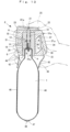
- a gas cylinder is stored into a pipe body putting a cover thereon, a plate- shaped nozzle forming a jetting port at the lower end is attached, a pusher guide is attached on the top of the pipe body, and a pusher having a needle on the guide is attached slidably.
- a cylinder receiver is attached inside of the pusher guide, and a screw of the mouth part of the gas cylinder is screwed up for the receiver.
- a safety plate is plugged in the pusher to stop the moving.
- the above-mentioned fire extinguisher has following problems.
- An operation of the safety plate may be confusing when putting out a sudden fire and small grasping portion makes it difficult to pull out the safety plate.
- the jetting gas is guided to a space between the pipe body and the gas cylinder. Since the gas is jetted from the jetting port, which is positioned at the opposite side of the seal piercing point, it attenuates pressure, speed and an effect in fire fighting, making initial fire fighting incomplete.
- the jetting gas remains inside of the pipe body after the seal piercing so that some amount of gas remains unused in the pipe body.
- a car is equipped with an emergency escape device so as to be able to escape from a car in case of an emergency, such as collision.
- the escape equipment is formed in shape of bar and is provided with a cutter for cutting a seat belt at one end.
- a hammer capable of breaking a windshield is provided at the other end or the end and set it in a holder. It is installed around a driver's seat or an appropriate place in a car to prepare for an emergency. (For example, see, patent document 2 and 3)
- the cutter is arranged with the edge fixed downwardly in a generally V-shaped groove between a periphery of a body and a guide, which protrudes toward a head part of the body.
- a side of the seat belt connects the edge of the cutter at generally right angles. Therefore, the seat belt cannot be cut promptly and smoothly.
- This invention provides a fire extinguisher gas ejector according to the appended claims, which easily and quickly removes the safety member and pierce the seal of the charged small gas cylinder and jet the gas properly and attempt early fire extinction.
- This invention comprises the emergency escape mechanism from vehicle, which cuts a seat belt promptly and breaks the windshield surely such as a fire in vehicle and collision, and attempts a prompt escape from vehicle. Moreover, it does not require a device exclusive to escape. Mechanisms for both fire extinction and escaping are rationally constituted.
- the hammer can rationally and safely be attached to the gas cylinder.
- the invention has the control valve, which prevents a waste of the extinguishing gas and jets the fire extinguishing gas to an origin of a fire surely and accurately in fire fighting.
- reference numeral 1 represents a known and small gas cylinder which is charged with carbon dioxide as an extinguishing gas.
- the gas cylinder of Fig. 1 to 14 does not form part of the invention.
- a mouth part of the gas cylinder 1 is provided with a piercing device 2.
- the gas cylinder 1 of Figures 1 to 14 requires about 40 mm in external diameter, about 130 mm in length, and about 90 ml in tare weight and is charged with carbon dioxide of about 4MPa therein.
- the weight after charging is about 300g.
- the mouth part is sealed with the sealing plate 3 and a hammer, which is described later, is attached to a bottom.
- a thread part 4 is formed on a periphery of the mouth part for the gas cylinder 1 and is screwed to the piercing device 2 to be fixed.
- the seal piercing device 2 is formed in a shape of an irregular tubular with strong and light synthetic resin.
- the seal piercing device 2 is composed of double pipes.
- One is a cylinder holder 5 which has a lower end capable of screwing the thread part 4.
- the other is an outer pipe 6, outer shell, which has a hollow tubular shape and is arranged outside of the cylinder holder 5.
- the cylinder holder 5 is formed in shape of virtually cylindrical with aluminum and has a screw hole 7 at the lower end capable of screwing the thread part 4.
- the cylinder holder 5 has a through hole 8 which communicates with the screw hole 7 and a hole 9 which is a little smaller than the through hole 8 therein to communicate each other in the coaxial direction.
- the seal piercing pipe 10, which will be described later, is inserted slidably the through hole 8 and the hole 9.
- reference numerals 11 and 12 represent O-rings.
- the O-ring 11 is inserted in a step of dividing part between the through hole 8 and the hole 9.
- the O-ring 12 is inserted in a annular groove between the screw hole 7 and the through hole 8.
- the middle to upper periphery of the cylinder holder 5 has a jetting port 13 which constitutes a jetting flow path together with the through hole 8 and a nozzle hole, which will be described later.
- a nozzle hole 14, which communicates with the through hole 8, is formed in the inner part of the jetting port 13.
- a pair of positioning pins 15 is protruded from the outer periphery of the cylinder holder 5 to the diameter direction and the pins 15 are fitted to the pin holes that are formed on inner surfaces of outer pipe pieces, which will be described later.
- Outer pipe pieces 6a, 6b are connected to predetermined positions to prevent dislocation of guide holes 31a, 31b, connecting surfaces 38a, 38b, and recessed grooves 38a, 38b.
- a pair of recess holes 16 are formed at the positions of 90 degree from the jetting port 13 on the periphery of the cylinder holder 5.
- the positioning pins 15 are pressed in the recess holes 16 and the ends are protruded from the periphery.
- the piercing pipe 10 is formed in a shape of bar by processing aluminum bar.
- the upper half of the piercing pipe 10 is slidably inserted to the hole 9 and a large-diameter part 10a is formed on the middle part.
- the large-diameter part 10a is slidably inserted to the through hole 8.
- reference numeral 17 is an annular groove formed on the large-diameter part 10a.
- the piercing pipe 10 without providing the seal piercing pipe 10 and the needle tube 19 separately, these parts can be integrally constituted. Then, a number of parts are reduced and the structure becomes simpler. Accordingly, the piercing pipe 10 only has to be equipped with the tip part 19a at one end.
- reference numeral 20 represents a spring which is inserted between the end of the piercing pipe 10 and the sealing plate 3, and biased the piercing pipe 10 to move upwardly with the resilience.
- the piercing pipe 10 has a contracted square shank 21 at upper end.
- the square shank 21 is fitted to a square hole 22a which is formed on the bottom surface of a seal piercing knob 22, which is the seal piercing member, and they are fixed together by using adhesive.
- adhesive instead of using adhesive on the square shank 21 and the square hole 22a, it is possible to fix them by screwing from the top of the seal piercing knob 22 or using a retaining ring.
- the seal piercing knob 22 is formed in a shape of virtually elliptical plate with synthetic resins, on which the top surface is gently recessed so as to be able to put a finger.
- a chevron-shaped rib 23 is projected on the front peripheral edge and a knob of a tab 24 is arranged overlapped on the base side of the rib 23.
- the tab 24 is formed by bending the synthetic resin rod, which has the same quality as of the piercing device 2, into a shape of virtually triangular, and the knob 24a is formed by bending the apex diagonally upward.
- the knob 24a is disposed on the middle part of top surface of the seal piercing knob 22 to be able to put the finger 25 thereon.
- the knob 24a can be pulled up with a connecting part 26, which protruded from back end, as a fulcrum.
- the connecting part 26 is formed diagonally downward, with the lower end connected to the rear end of the safety plate 27.
- the safety plate 27 is formed with the same member as the tab 24 and is shaped in an elliptical plate, which is little larger than the tab 24.
- the notch 28 is formed in the front-back direction on the half front of a safety plate 27, and a notch 28 is engaged with upper part of the seal piercing pipe 10.
- the safety plate 27 is usually inserted between the seal piercing knob 22 and the upper surface of the outer pipe 6.
- the piercing pipe 10 is engaged with the notch 28 to prevent pulling out the safety plate 27 and pressing the seal piercing tab 24.
- the tab 24 is raised and pulled up, the safety plate 27 can be pulled backwardly along the notch 28.
- the outer pipe 6 is constituted with two pieces that are split in the axial direction along a jetting port guide, which will be described later, and the cylinder holder 5 is stored therein.
- Connecting surfaces 29a, 29b, are integrally attached as one with heat welding.
- the outer pipe pieces 6a, 6b can be joined together by screwing or using adhesive instead of heat welding.
- Irregular-shaped engaging holes 30a, 30b capable of storing the cylinder holder 5 are symmetrically formed on the connecting surfaces 29a, 29b of the outer pipe pieces 6a, 6b.
- One side of the connecting surfaces 29a, 29b have guide holes 31a, 32b that constitute a funnel-like jetting port guide 31.
- reference numerals 32a, 32b represent pin holes that are formed on the inner surfaces of the engaging holes 30a, 30b permitting the positioning pin 15, 15 to be inserted.
- a chevron-shaped protrusion 33 is formed in the axial direction on the back periphery of the outer pipe 6, and a seat belt guide 34 is protruded outside of the protrusion 33 obliquely downward from the upper end of the outer pipe 6, virtually parallel with the protrusion 33.
- a seat belt introduction groove 36 capable of inserting a seat belt 35 is formed between the seat belt guide 34 and the protrusion 33, facing the inner surface of the introduction groove 36 each other.
- a cutter 37 is arranged at upper part of the introduction groove 36.
- An edge of the cutter 37a is vertically arranged, and acutely arranged with respect to the direction of introducing the seat belt 35.
- the seat belt 35 can be cut at sharp angle with respect to a direction of the thickness of the seat belt 35.
- the seat belt guide 34 is constituted by joining guide pieces 34a, 34b that extend from outer pipe pieces 6a, 6b.
- Concaved grooves 39a, 39b that are virtually parallelogram shape, are formed in axial direction over the joining surfaces 38a, 38b and the connecting surfaces of 29a, 29b of the outer pipe pieces 6a, 6b.
- the cutter 37 is stored in the concaved groove 39a, 39b.
- a pin 40 protrudes from the recessed grooves 39a, 39b are inserted in a fitting hole 41 formed on the cutter 37 to prevent displacement.
- the outer pipe 6 has lower periphery on which the front and back sides are concavely curved, and the cross sectional view is an elliptical shape.
- Curved concaved parts 42, 43 respectively have a concave part 44 and a convex part 45 that form curved patterns for to make friction so that the part can easily or firmly grasped.
- the outer pipe 6 has skirt-like peripheries on lower part and the skirt-portions are arranged apart at the outside of the periphery of the shoulder part. These spaces block heat conduction, which lowers a temperature of the surface of the gas cylinder 1 when the extinguishing gas is jetted. Thus, the temperature drop of the curved concaved parts 42, 43 is inhibited.
- the gas cylinder 1 has a sheet 46 made of heat insulating film on the middle periphery with printed pictures thereon that show how to use of the fire extinguisher gas ejector. The heat insulation action is obtained when putting out a fire.
- the film made of synthetic resin is used for the sheet 46, the film is attached by shrinking with predetermined temperature on the surface of the gas cylinder 1 which is filled with carbon dioxide.
- the hammer 47 having the pointed part is attached to the exposed bottom of the gas cylinder 1, and a hammer 47 is molded by sintering to a predetermined hardness with a prescribed powder metal.
- the hammer 47 is shaped in a thin, concavely or convexly curved plate capable of contacting the bottom of the gas cylinder 1.
- a pointed part 48 which is a cone shape, is protruded from the center of the convex surface side.
- the hammer 47 After molding to the predetermined shape with sintering, the hammer 47 is prepared to high hardness by quenching with the predetermined temperature.
- the prepared hammer 47 is attached to the bottom of the gas cylinder 1, which is filled with carbon dioxide, by spot welding or welding.
- the hammer 47 can be attached to the gas cylinder 1 smoothly and safely without changing a conventional process or filling facility of carbon dioxide for the gas cylinder 1.
- the hammer 47 can also be attached by bonding or brazing instead of spot welding.
- a thick steel plate is press molded to said shape instead of molding the hammer 47 with sintering, and the hammer can also be attached by spot welding, welding, bonding, or soldering.
- reference numeral 49 shows the extinguishing gas jetting for outside from the jetting port guide 31 after the seal is pierced.
- Reference numeral 50 shows a windshield of a car.
- the fire extinguisher gas ejector which is constituted by the way above, is constructed by attaching the piercing device 2 on top of the small gas cylinder.
- the small gas cylinder 1 is constituted by attaching the hammer 47 for an emergency escape.
- the piercing device 2 is constituted with the piercing pipe 10, the piercing knob 22, the safety plate 27 which is integrally formed with the tab 24, and the cutter 37 for cutting a seat belt for escaping in case of an emergency.
- the hammer 47 When making a fire extinguisher gas ejector, the hammer 47 is molded by sintering. After the sintering, the hammer 47 is prepared for predetermined hardness and is attached to the bottom of the small gas cylinder 1 by spot welding.
- the piercing device 2 is produced by combining following parts.
- the pointed part 48 is prepared for high hardness by quenching with a predetermined temperature.
- the hammer 47 When attaching the hammer 47, which is produced by the way above, to the gas cylinder 1, the hammer 47 is spot welded to the gas cylinder 1 which is filled with the extinguishing gas, carbon dioxide, and sealed with the sealing plate 3.
- the spot welding is carried out by connecting the concavely curved surface of the hammer 47 with the bottom of the gas cylinder 1, energizing, and welding. The state is shown in the Fig. 9 .
- the spot welding temporarily causes high temperature.
- the filled carbon dioxide has no risk for an ignition, explosion, or a sudden expansion. After the spot welding, the current state is promptly recovered so that the operation of spot welding is performed safely.
- the sealing plate 3 is also sealed by spot welding after filling the carbon dioxide. This suggests that it is safe to carry out a spot welding to the gas cylinder 1.
- the spot welding to the gas cylinder 1 is carried out after the carbon dioxide is filled. Therefore, filling operation of the carbon dioxide can be carried out in a conventional manner by using filling facilities that already exist. It will not reduce the productivity and the efficiency.
- brazing requires lower temperature compared to spot welding. It reduces effects of temperature of brazing on filled gas and thermal stress. At the same time, similar advantages and strength can be obtained as spot welding.
- a thick steel plate is press molded into the above-mentioned shape and it can also be attached by spot welding, bonding or brazing instead of molding the hammer 47 with sintering.
- the sheet 46 is attached on the middle periphery of the gas cylinder 1.
- a film made of synthetic resin is used for the sheet 46 with printed pictures that show usage of the fire extinguisher gas ejector. Then, the film is cut to a predetermined size and formed in shape of roll. The periphery of the gas cylinder 1 is covered with the sheet, and then, shift it into a heat furnace with predetermined temperature for heat contraction. The shrunk film is attached on the middle periphery of the gas cylinder 1.
- the outer pipe pieces 6a, 6b, the piercing knob 22, and the safety plate 27 are separately resin molded, the cylinder holder 5 and the piercing pipe 10 are machine processed with different diameter aluminum bars, and the cutter 37 is produced by press molding the steel plate.
- outer pipe pieces 6a, 6b are formed by cutting axially the outer pipe 6 into half at the position of the jetting port guide 31. And the center of the connecting surfaces 29a, 29b of the cylinder body side have the engaging holes 30a, 30b and the engaging holes 30a, 30b have the pin holes 32a, 32b on the middle.
- one sides of the connecting surface 29a, 29b have the guide holes 31a, 31b that constitute the jetting port guide 31.
- the concaved grooves 39a, 39b that store the cutter 37 are formed on the other sides.
- the guide pieces 34a, 34b are integrally protruded from the outside of the cylindrical body side.
- a part of the concaved grooves 39a, 39b is formed on the connecting surfaces 38a, 38b.
- the curved concaved parts 42, 43 are disposed on front and back peripheries of the outer pipe pieces 6a, 6b.
- the curved concaved part 42 of front side has a plurality of the concaved parts 44
- the concaved part 43 of back side has a plurality of the convex parts 45.
- the seal piercing knob 22 is shaped in an elliptical plate which has longer major axis in front and back and the top surface is gently concaved and curved.
- the chevron-shaped rib 23 is protruded from the front side and square hole 22a is disposed on the lower surface.
- the safety plate 27 and the tab 24 are integrally formed. Of them, the safety plate 27 and the seal piercing knob 22 are shaped in virtually the same elliptical plate, and the notch 28 is disposed on the front side.
- the tab 24 is formed in a shape of regular triangular by using a flat bar and the knob 24a is formed by turning up the front obliquely upward.
- the rear of the knob 24a is connected to the back of the safety plate 27 by the connecting part 26, which protruded obliquely downward.
- the cylinder holder 5 is formed cylindrical in which the through hole 8 and the hole 9 are formed therein.
- the holes are smooth and have different diameters.
- the lower part of the cylinder 5 has the screw hole 7, and the jetting port guide 13 and the nozzle hole 14 that are disposed on the middle circumference are communicating with the through hole 8.
- a pair of recessed holes 16 is disposed diametrically on the surface of the circumference of the cylinder holder 5.
- the pins 15, 15 are pressed into the recess hole 16.
- the seal piercing pipe 10 is formed in a bar shape, the large-diameter part 10a and the annular groove 17 are disposed on the middle, and the square shaft 21 are formed on the top end.
- One end of a steel pipe is obliquely cut to make the needle tube 19, one end of the tube 19 is pressed into lower end of the piercing pipe 10, and the tip part 19a is protruded outside.
- the needle tube 19 can be omitted if the piercing pipe 10 is integrally provided with the tip part 19a.
- the cutter 37 is produced by press molding a steel plate, and the fitting hole 41 is disposed on the middle, and the edge of the cutter 37a is disposed on the side edge.
- the piercing device 2 is produced by assembling them.
- the engaging hole 30a of the outer pipe piece 6a is stored in the cylinder holder 5, the positioning pin 15 is inserted to the recess hole 32a, the cutter 37 is stored in the recessed groove 39a, and the fitting hole 41 is inserted to the pin 40.
- an electrical heat plate (not shown) is inserted between the connecting surfaces 29a, 29b. Then, applying current to the electrical heat plate and heated to a melting temperature. After the connecting surfaces 29a, 29b are melted, the electrical heat plate is pulled out, connecting surfaces 29a, 29b are welded, and the cutter 37 and the cylinder holder 5 are integrally buried therein.
- the piercing pipe 10 is inserted from the lower side of the through hole 8 of the cylinder holder 5 of the connected outer pipe 6.
- the top end of the square shaft 21 is protruded from the hole 9, the square hole 22a of the seal piercing knob 22 is fitted into the square shaft 21 with the rib 23 facing front, and they are connected together and fixed.
- the square shaft 21 and the seal piercing knob 22 can be fixed by screwing or can be attached with a retaining ring.
- the safety plate 27 is inserted therebetween.
- the notch 28 is inserted to the top of the piercing pipe 10 with the safety plate 27 sandwiched, and the assembly of the piercing device 2 is completed when the tab 24 integrally formed with the safety plate 27 is attached on the seal piercing knob 22.
- assembled piercing device 2 is composed about 83 mm high, about 60 mm long in front-back direction, and about 43 mm in external diameter.
- the fire extinguisher gas ejector which loaded the gas cylinder 1, is shown in the Fig. 1 to Fig. 3 and is constituted small and lightweight, 183 mm high and weigh 460g. Unlike conventional ones, it does not require a case that covers the outside of the gas cylinder 1 so that the constitution becomes simpler and lightweight. Accordingly, it can be produced easily and at low cost.
- the cutter 37 and the hammer 47 are provided with the gas cylinder 1 and piercing device 2, essential components for the fire extinguisher gas ejector. It does not require an exclusive device for escaping so that the mechanisms for fire extinguishing and escaping are constituted rationally. As for advantages, these functions can be used simply.
- the assembled fire extinguisher gas ejector has the tab 24 with the knob 24a raised and exposed on the seal piercing knob 22, and the safety plate 27 integrally formed with the tab 24 is located between the seal piercing knob 22 and the outer pipe 6.
- the jetting port guide 31 is located at middle and high position on front of the outer pipe 6, the seat belt guide 34 is protruded obliquely downward, and the edge 37a of the cutter 37 is perpendicularly disposed in the upper seat belt introduction groove 36.
- the curved concaved parts 42, 43 that form the grasping part are located immediately below the jetting port guide 31 and the seat belt guide 34.
- the upper part of the gas cylinder 1 is located inside of the concaved parts 42, 43 via space.
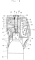
- the mouth part for the gas cylinder 1 is sealed with the sealing plate 3 as shown in Fig. 4 , the piercing pipe 10 is located immediately above the sealing plate 3 to be able to move up-and-down, the piercing pipe 10 is biased upwardly to move with the resilience of the spring 20 and the tip part 19a of the needle tube 19 is located immediately above the sealing plate 3.
- the sheet 46 is attached to cover the middle periphery of the cylinder 1, the hammer 47 is disposed to the bottom of the cylinder 1, and the pointed part 48 is downwardly exposed.
- a suitable cover is removably attached on the pointed part 48.
- a cross sectional view of the piercing device 2 is formed in a shape of elliptical which has a major axis in front and back direction so that rolling motion, abnormal noise and damage of fire extinguisher gas ejector can be prevented when it is put transversely.
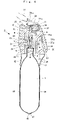
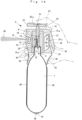
- the seat belt 35 When the device is installed on a car and if the seat belt 35 cannot be taken off or/and a door does not open by a traffic accident, the seat belt 35 need to be cut and/or a windshield 50 needs to be broken when a driver or other member evacuate outside of the car.
- the curved concaved parts 42, 43 are grasped facing the seat belt introduction groove 36 of the piercing device 2 front, the seat belt 35 is inserted into the seat belt introduction groove 36 to contact the edge 37a of the cutter 37, and the piercing device 2 is pulled down to slice through the seat belt 35.
- the state is shown in the Fig. 2 .
- the seat belt introduction groove 36 is obliquely and downwardly open with respect to the axial direction of the piercing device 2 so that the seat belt 35 can be smoothly inserted by the chevron-shaped protrusion 33 compared to a one which has a groove opens perpendicularly and downwardly.
- edge 37a of the cutter 37 is disposed at an acute angle with respect to the introduction direction of the seat belt 35.
- the edge 37a of the cutter 37 cuts into the side edge of the seat belt 35 and prompt smooth cutting, compared to a edge of a cutter is disposed at right angle with respect to the seat belt introduction groove.
- the fire extinguisher gas ejector When breaking the windshield 50, the fire extinguisher gas ejector is grasped with the bottom pointing a car side window or windshield, as with the case cutting the seat belt 35. Then, a windshield 50 is smashed with the pointed part 48 of the hammer 47 by smashing and striking the windshield 50. This state is shown in Fig. 11 .
- the windshield 50 when breaking the windshield 50 after the seatbelt 35 is cut, the windshield 50 can be broken in continuous motion without shifting the fire extinguisher gas ejector.
- the seat belt 35 when cutting the seat belt 35 after breaking the windshield 50, the seat belt 35 can be cut in continuous motion without shifting a fire extinguisher gas ejector.
- the action can be carried out quickly and safely compared with the one, which dispose the seat belt introduction groove 36 and the hammer 47 at the same side or different position.
- the hammer 47 is disposed apart from the seat belt introduction groove 36 so that the windshield 50 is smashed surely and there is no fear of being injured.
- the tab 24 is configured the same as a known tab for opening a beverage container so that an operation for pulling the knob 24a up is easily understandable. It is possible to respond to a fire in a car, which needs quick operations.
- the safety plate 27 is moved backward against the engaging force of the piercing pipe 10 and the notch 28, and the safety plate 27 is pulled out backwardly.
- the state is show in Fig. 12 .
- the top surface of the seal piercing knob 22 is exposed, and a space, which is the same thickness as the safety plate 27, is formed between the seal piercing knob 22 and the top edge of the outer pipe 6.
- the fire extinguisher gas ejector is shifted to grasp the curved concaved parts 42, 43 and the piercing device 2 as shown in Fig. 12 .
- the finger 25 is put on the top of the seal piercing knob 22 and press down the seal piercing knob 22.
- the state is shown in Fig. 14 .
- the needle tube 19 is moved immediately above the sealing plate 3, the pierced point of the sealing plate 3 is communicated with the through hole 8, and the through hole 8 is communicated with the nozzle hole 14 and the jetting port 13.
- the filled gas is jetted from a pierced hole to the through hole 8 and it is introduced from the nozzle hole 14 to the jetting port 13. Then, the gas is jetted outside from the jetting port guide 31 and sprayed onto the source of the fire. At this time, a part of the carbon dioxide is adiabatically expanded to become dry ice after jetting the filled gas and it is mixed with the gaseous carbon dioxide and jetted toward the origin of a fire.
- the latent heat cools and absorbs the heat of the surface of the gas cylinder 1.
- the skirt part which is close to the cylinder 1 and lower side of the piercing device 2, prevents heat conduction by a space disposed inner side so that the finger 25 is not affected.
- the fire extinction continues until all the filled gas is completely used so that the filled gas can be effectively used. Thus, the effectiveness of the fire extinction is increased.
- the empty gas cylinder 1 can be easily recovered after detaching the gas cylinder 1 from the screw hole 7 of the cylinder holder 5.
- Fig. 15 to Fig. 28 shows other embodiments some forming part of the present invention and others not forming part of the present invention, and identical numerals are used for the parts that have the same constitution with the above-mentioned embodiment.
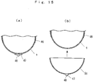
- FIG. 15 is an embodiment not forming part of the present invention showing the hammer 47.
- the hammer 47 which is made from sintered metal or press molded steel plate is attached to the bottom of the gas cylinder 1 to alleviate a concern over strength reduction of the gas cylinder 1 due to thermal stress by heating of spot welding and brazing.
- the hammer 47 is insert molded by use of a bowl-shaped plastic cylinder cover 51.
- the cover 51 is attached to the exposed bottom of the gas cylinder 1 so that the cover 51 is rigidly attached.
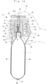
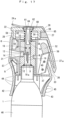
- Fig. 16 to Fig. 22 is the embodiment of the present invention showing other cutting form of the seat belt 35, the other form of the hammer 47, and installed form of the fire extinguisher gas ejector in a car.
- the edge 37a of the cutter 37 is disposed obliquely downward in the middle of the seat belt introduction groove 36, and a seat belt releasing part 52 is disposed with a space at the rear of the cutter 37.
- the seat belt releasing part 52 is integrally formed with the joining part 53, which is disposed back of the seat belt introduction groove 36.
- the joining part 53 is constituted by attaching a pair of joining pieces 53a, 53b that connect the seat belt guide 34 and the outer pipe 6, and the seat belt releasing part 52 is protruded adjacent to the neck portion 54 of the joining part 53.
- the seat belt releasing part 52 is constituted by connecting a pair of seat belt releasing part pieces 52a, 52b.
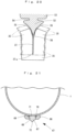
- the cross sectional view has a shape of inverted triangular, which the width increases as it goes to the back of the seat belt introduction groove 36 from the distal end, the seat belt releasing part 52 has wider width except the distal end than the thickness of the cutter 37, and the periphery which curves outside forms the seat belt releasing surface 55.
- reference numeral 56 indicates a space between the cutter 37 and the seat belt releasing part 52.
- the cylinder holder 5 is formed by aluminum and has the through hole 8 therein, which communicates with the nozzle hole 14.
- the cylinder holder 5 is buried in the inner pipe cover 57, which is made of synthetic resin, as a insert fixture to make them integrated.
- the jetting port 13 and the jetting port guide 31 are formed on the inner pipe cover 57, and the outer pipe 6 is disposed outside of the inner pipe cover 57.
- Upper part of the outer pipe 6 has a pair of guide holes 58, and the guide pin 59, which is integrated with the seal piercing knob 22, is slidably inserted to the guide hole 58.
- the seal piercing knob 22 has a flat surface top and a recess hole 60 on the center.
- the threaded shaft 61 which is provided on the top end of the seal piercing pipe 10 is disposed in the recess hole 60, and the seal piercing knob 22 is attached to the piercing pipe 10 by screwing the nut 62 into the threaded shaft 61.
- the spring 63 which is inserted between the top end surface of the inner pipe cover 57 and a flanged part of the upper end of the piercing pipe 10 is used as a substitute of the spring 20 which is disposed around the needle tube 19.
- the resilience of the spring 63 biased the seal piercing knob 22 upwardly.
- reference numeral 64 shows a cap, which closes the recess hole 60.
- the tab 24 of the embodiment of the invention is disposed immediately above the end of the seal piercing knob 22 with the knob 24a extended.
- the safety member 27, which is integrally formed with the tab 24, is formed in a shape of a ring from a plate. This arrangement promotes the operation of pulling the tab 24 up with notches 65, 66 as a fulcrum and the operation of pulling the safety member 27 out.
- Fig. 17 shows the statement of the embodiment of the invention in which before the seal is pierced.
- the spring 63 biased the seal piercing knob 22 upwardly, intervening the safety member 27 just under the seal piercing knob 22.
- the tab 24 is located immediate above the seal piercing knob 22 and the tab 24 is normally restrained to the seal piercing knob 22 with an adhesive seal (not shown).
- the piercing knob 22 is pressed down against the spring 63 and the piercing pipe 10 is pressed down, and it moves the needle tube 19 in accordance with the move of the piercing pipe 10.
- the sealing plate 3 is pierced with the tip part 19a of the needle tube 19. The state is shown in Fig. 18 .
- the extinguishing gas in the gas cylinder 1 is jetted out, pushing up the piercing pipe 10 by the extinguishing gas through the needle tube 19.
- the gas comes to the through hole 8, then the gas is introduced from the nozzle hole 14 to the jetting port guide 31 and is jetted outside.
- Fig. 20 The state is shown in Fig. 20 . Firstly, the side of the seat belt 35 is cut through with the edge 37a of the cutter 37, and then the cut part is split in two sides along with the cutter 37 and moved to the back of the seat belt introduction groove 36.
- the cut part is divided from the distal end and is moved to the back along with the both sides of the belt releasing surface 55, push opening the cut part.
- the spreading function reaches the other side of the seat belt 35, that is the cutting part side. It prevents the seat belt 35 and the cutter 37 from contacting both sides closely or stagnating. It promotes the seat belt 35 to move to the back smoothly.
- the seat belt 35 moves smoothly without stagnation from the seat belt releasing part 52 to the edge 37a of the cutter 37 and smooth and quick cutting is carried out by the cutter 37.
- Fig. 21 is an enlarged view of the hammer 47 that is applied to the embodiment of the invention.
- the hammer 47 of this embodiment of the invention is structured with the steel retaining ring 66 and the hammer shaft 67 which quenched steel hard material.
- the retaining ring 66 is formed in a shape of plate and has the hole 68 in center. After the retaining ring 66 is welded to the bottom of the gas cylinder 1, the hammer shaft 67 is inserted to the hole 68 together with the stopper, the C-ring 69. After the insertion, the tapered surface 70, which is inner rim of the hole 68, is engaged with the C-ring 69 to attach the hammer shaft 67 closely.
- the hammer shaft 67 has a shape of axis which is longer than the height of the retaining ring 66, the annular groove 71, the neck portion, is formed on the base, the pointed part 72 is formed at the end, and the pointed part 72 is protruded form outside of the retaining ring 66.
- the welding of the retaining ring 66 is carried out after the carbon dioxide is charged to predetermined pressure and the mouth part is sealed with the sealing plate 3. After the welding of the retaining ring 66, the gas cylinder 1 and the retaining ring 66 are plated at the same time.
- the tapered surface 70 of the inner rim of the hole 68 is engaged with the spherical surface of the C-ring 69 with the elasticity.
- the C-ring 69 is attached by pressure to the tapered surface 70 so that the wedge effect is obtained.
- the adhesive is put in the gap among the gas cylinder 1, the C-ring 69, and the hammer shaft 67, and then fixed to attach the hammer shaft 67 stiffly and tightly.
- the retaining ting 66 is welded to the gas cylinder 1.
- the processes of welding and plating the hammer shaft 67 to the gas cylinder 1 are avoided by engaging the hammer shaft 67 to the retaining ring 66.
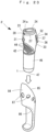
- the Fig. 22 shows the fire extinguisher gas ejector, which is installed in a car.
- the storing case 75 which is like a elongated shape bag and stores the piercing device 2 with the gas cylinder 1 is stored in the concaved door pocket 74 which is provided with the inner side of a door 73 adjacent to the driver's seat.
- the storing case 75 is made by sewing a plate of soft foamed polyurethane resin. It is structured with one end closed and the other end is open. The opening side has one end of the open-close belt 76, which is attached detachably.
- attaching belts 77, 78 are respectively attached to the periphery of the storing case 75 and the simple stopper 79 such as a hook is disposed at the other ends, and a stopper 79 is removably attached to a stopper (not shown), such as a hook, which is buried outside wall of a door pocket 74 to fix a storing case 75 in place.
- a strap 80 is attached to the other ends of the attaching belt 77, 78 and stuck out to face a driver's seat.
- the fire extinguisher gas ejector When using the fire extinguisher gas ejector, hold the strap 80 with one hand and pull up to remove the fixation of the stopper. Then the storing case 75 is taken out from the door pocket 74.
- reference numeral 82 shows a door trim and 83 shows a power window device.
- Fig. 23 to Fig. 25 shows an embodiment of the present invention.
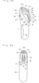
- the embodiment shows a bottomed protective case 84 for storing the piercing device 2 and the bottom of the case 84 covers the hammer 47.
- the piercing device 2 For easy carrying and safety of the piercing device 2, it is installed, inside of a headrest and an appropriate place of a mat (not shown) to the fixed position by using a clip.
- the protective case 84 is shaped like a vertically long bag using light and soft resin foam.
- a lower opening 86 is formed on the lower part of the other side of the upper opening 85 of the protective case 84, with the periphery of the gas cylinder 1 located exposed from the lower opening 86.
- reference numeral 87 shows a plurality of open holes that have different diameters formed around the upper opening 63. One of them is opened to correspond with the jetting guide 31.
- the piercing device 2 when breaking the windshield 50, the piercing device 2 is taken out from the protective case 84 to carry out an operation.
- the upper opening 85, the lower opening 86, and the open hole 87 loosen the contact or adhesion between the protective case 84 against the piercing device 2 so that the piercing device 2 is taken out smoothly from the protective case 84.
- Fig. 26 to Fig. 28 shows an embodiment not forming part of the present invention.
- a waste of the extinguishing gas is prevented by stopping discharging the extinguishing gas, which is jetted from the gas cylinder after the seal is pierced.
- the gas can be jetted accurately toward a fire origin, and the effective use of the gas and initial fire fighting can be achieved. It shows the fire extinguisher gas ejector having the control valve for household use or in car use, which has simpler structure by reducing the number of the part.
- reference numeral 88 shows a case, which has a shape of a virtually hollow tubular, made of synthetic resin. It is structured by joining a pair of cut cases that are formed by cutting the center in half in the longitudinal direction.
- the case has a screw part 89 on the lower periphery and a bottomed cap 90 is attached thereto.
- the case 88 has an opening 91 at top end and an operating lever 92, which is a piercing member, is attached to the opening 91 to rotate up and down.
- the operating lever 92 is structured with a synthetic resin plate which has virtually the same width of the opening 91, one end has a protruded pin 93 which is slidably inserted to a long hole 94 formed on the case 88, and the other end is protruded from outside rear of the case 88.
- reference numeral 92a is an engaging convex portion, which protruded in the center of the undersurface of the operating lever 92. It is disposed engageable to the top end of the control valve, which will be described later, and a safety pin 95 is inserted to the engaging convex portion 92a.
- Numeral 92b is a concaved finger grip portion, which is formed on the other end of the operating lever 92 and protrudes backward from the case 88.
- the safety pin 95 is inserted by penetrating the center of the operating lever 92 and the case 88.
- One end of the gasping portion protrudes outside of the case 88, making impossible to press the operating lever 92 in normal times or to pierce the seal accidentally.
- an operation of pressing the lever 92 can be performed.
- the small gas cylinder 1 is stored inside of the case 88, with the bottom stored in the cap 90.
- the periphery of the gas cylinder 1 is formed with the thread part 4 and the thread part 4 is attached to the screw hole 7 of the cylinder holder 5 by screwing.
- the cylinder holder 5 is formed in a shape of cylinder by aluminum die-casting. There is an opening for the screw hole 7 at the lower end and the through hole 8, a valve hole 96, and a hole 97 are disposed to communicate one another at the upper part of the thread hole 7. The respective inner diameters are formed to become smaller.
- the middle to upper periphery of the cylinder holder 5 is provided with the jetting port 13, which communicates with the jetting port guide 31, formed on the case 88, and the bottom of the jetting port 13 is disposed with the nozzle hole 14, which communicates the valve hole 96.
- the control valve 98 which is integrally formed with the piercing pipe 10, is slidably inserted to the valve hole 96, and the top end is disposed to appear on top of the cylinder holder 5.
- the top end is disposed engageable with the engaging convex portion 92a when it protrudes.
- tubular structure is not necessarily required for the needle tube 19.
- the control valve 98 is formed in a shape of stepped bar, and at least a pair of O-rings 99, 100 are mounted to the positions of upper and lower of the periphery of the large diameter part, enabling the valve hole 96 and the nozzle hole 14 to be air tightened by the O-rings 99, 100.
- the spring 20 is inserted between the lower end of the control valve 98 and the sealing plate 3, and the resilience of the spring 20 biased the control valve 98 upwardly.
- the stepped portion 98a which is formed on the middle of the control valve 98, is able to be engaged with the rim of the lower opening of the hole 97.
- the control valve 98 is, in normal times, able to close the nozzle hole 14 by positioning the O-ring 100, which is disposed lower side, at inner rim of the nozzle hole 14.
- the long hole 94 controls the descending displacement of both the operating lever 92 and the control valve 98
- the O-ring 99 which is disposed upper side, is positioned at inner rim of the nozzle hole 14 to be able to close the nozzle hole 14.
- the O-rings 99,100 are respectively positioned at inner rim of the nozzle hole 14, the lower O-ring 100 is positioned at the side of the through hole 8, and the nozzle hole 14 is communicated with the through hole 8 to be able to jet the extinguishing gas from the nozzle hole 14.
- reference numeral 101 shows a concaved part formed on the top of the cylinder holder 5, and a lever spring 102 is inserted between the concaved part 101 and the opening lever 92. The resilience of the spring 102 biased the operating lever 92 upwardly.
- Numeral 3a shows a sealed hole of the sealing plate 3.
- an outer housing, a piercing holder, a pin, and a pushrod, the parts to be disposed around the cylinder holder 5 in a conventional fire extinguisher gas ejector are omitted. Only the cylinder holder 5 is disposed upside of the case 88 so that the number of the parts are reduced and they are easily assembled. Thus, small and light structure and low cost of the fire extinguisher gas ejector can be achieved.
- control valve 98 of this embodiment not forming part of the invention requires only to form the annular groove, which attaches two O-rings 99,100 at the predetermined position of the periphery of the piercing pipe 10.
- the structure is simpler and the less number of the parts is required. Therefore, it is produced easily and inexpensively.
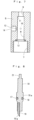
- the fire extinguisher gas ejector is used as follows.
- the cap 90 is removed before use, the gas cylinder 1 is inserted from the bottom of the case 88, the thread part 4 of the mouth part is screwed to the screw hole 7 of the cylinder holder 5 to attach the gas cylinder 1, and the cap 90 is screwed to the lower end of the case 88.
- the O-ring 100 is positioned at inner rim of the nozzle hole 14 to close the rim and intermit the guide hole 8, valve hole 96, and the nozzle hole 14.
- the resilience of the spring 20 biases the control calve 98 upwardly and the top end is protruded from the top of the cylinder holder 5 to engage with the engaging convex portion 92a of the operating lever 92.
- the safety pin 95 is inserted to the operating lever 92 on the center, the pin 95 is engaged with the top end of the long hole 94 to stop an operation of the operating lever 92. Moreover, the needle tube 19 is located above the sealing plate 3 for the piercing operation. The state is shown in Fig. 26 .
- the safety pin 95 is pulled out by pulling a grasping portion (not shown) and the operating lever 92 is unlocked, the operating lever 92 is pressed down the upper center against the resilience of the spring 20.
- the needle tube 19 moves in accordance with the control valve 98, and the tip part 19a pierces the sealing plate 3.
- the state is shown in Fig. 27 .
- the O-ring 99 moves to the inner rim of the nozzle hole 14 to close the nozzle hole 14 and intermit the nozzle hole 14 and the through hole 8.
- the extinguishing gas is jetted swiftly to the through hole 8 from the pierced hole 3a of the sealing plate 3.
- the O-ring 100 stops the outflow of the gas from the nozzle hole 14, and the O-ring 99 prevents the leakage from the valve hole 96 and the gas stagnates in the through hole 8.
- a finger is put on a finger grip portion 92b and press the operating lever 92 down against the resilience of the lever spring 102. Then, the operating lever 92 rotates downward with the pin 93, which acts as a fulcrum, and the engaging convex portion 92a presses the piercing pipe 10 down.
- the O-ring 99, 100 moves lower, the O-ring 100 uncloses the nozzle hole 14 and moves to the upper part of the through hole 8, communicating the nozzle hole 14 with the through hole 8, and the O-ring 99 moves to immediate above the rim of the inner side of the nozzle hole 14 to seal the valve hole 96.
- the state is shown in Fig. 28 .
- the descending displacement of the piercing pipe 10 and the control valve 98 is less than when the seal is pierced. Therefore, the O-ring 99 does not close the nozzle hole 14, and the pierced hole 3a is not closed by inserting the needle tube 19.
- the nozzle hole 14 is remained open and the jetting of the extinguishing gas from the pierced hole 3a is remained.
- the extinguishing gas is jetted from the nozzle hole 14 to the jetting port 13 and jetted outside from the jetting guide 31 toward a fire origin.
- the extinguishing gas which is jetted after the piercing, is once stagnated in the through hole 8.
- the through hole 8 and the nozzle hole 14 are communicated with each other by the operation of the operating lever 92 after the seal is pierced, the extinguishing gas is accurately jetted to a fire origin.
- the O-ring 100 seals the nozzle hole 14, as mentioned above, the jetting of the extinguishing gas is stopped, and the O-ring 99 stops the leakage from the valve hole 96 and the gas stagnates in the through hole 8. Accordingly, the unused extinguishing gas after the seal piercing is used effectively.
- the fire extinguisher gas ejector of the present invention easily and quickly removes the safety member, pierce the seal of the small gas cylinder mounted therewith, and jet the gas promptly to attempt early fire extinction.
- This invention comprises the emergency escape mechanism from vehicle, which cuts a seat belt promptly and breaks the windshield surely in case such as a fire in vehicle and collision, and attempts a prompt escape from vehicle. Moreover, it does not require a device exclusive to escape. Mechanisms for fire extinction and escaping are rationally constituted.
- the hammer can be rationally and safely attached to the gas cylinder.
- the invention comprises the control valve, which prevents the waste of the extinguishing gas and jets the fire extinguishing gas to the origin of a fire surely and accurately in fire fighting.
- the present invention is suitable for a fire extinguisher, for example, used in a vehicle.
Description
- The present invention is suitable for a fire extinguisher gas ejector. This invention relates to a fire extinguisher gas ejector comprising a gas cylinder filled with extinguishing gas.
- Popular fire extinguishers placed at homes or offices are usually large-sized and heavy so that they require physical strength and hard to use.
- To solve above-mentioned problems, it is proposed that a variety of small and lightweight fire extinguishers that can be used simply.
- For example, of the simple fire extinguishers, a gas cylinder is stored into a pipe body putting a cover thereon, a plate- shaped nozzle forming a jetting port at the lower end is attached, a pusher guide is attached on the top of the pipe body, and a pusher having a needle on the guide is attached slidably. A cylinder receiver is attached inside of the pusher guide, and a screw of the mouth part of the gas cylinder is screwed up for the receiver. Usually, a safety plate is plugged in the pusher to stop the moving.
- Then, the safety plate is removed when putting out a fire and hit the outside of the pusher with a hand and pushes inwardly. Then a sealing plate is pierced by the needle which moves toward the gas cylinder side. A filled gas, which gushed, is guided to inside of a shaft from the inside of the pipe so as to jet the gas from a jetting port, which is positioned at the opposite side with the seal piercing position. (For example, see, Patent Document 1)
- However, the above-mentioned fire extinguisher has following problems. An operation of the safety plate may be confusing when putting out a sudden fire and small grasping portion makes it difficult to pull out the safety plate. After the seal is pierced, the jetting gas is guided to a space between the pipe body and the gas cylinder. Since the gas is jetted from the jetting port, which is positioned at the opposite side of the seal piercing point, it attenuates pressure, speed and an effect in fire fighting, making initial fire fighting incomplete. Moreover, the jetting gas remains inside of the pipe body after the seal piercing so that some amount of gas remains unused in the pipe body.
- On the other hand, the conventional simple fire extinguishers are usually placed at homes or offices, however, the demands to place them in vehicles is on the rise to cope with a fire in vehicles nowadays.
- In such cases, it is to be desired for a simple fire extinguisher used in vehicle to combine other functions rationally in addition to the function of a fire extinguisher.
- Due to such demands recently, a car is equipped with an emergency escape device so as to be able to escape from a car in case of an emergency, such as collision.
- The escape equipment is formed in shape of bar and is provided with a cutter for cutting a seat belt at one end. A hammer capable of breaking a windshield is provided at the other end or the end and set it in a holder. It is installed around a driver's seat or an appropriate place in a car to prepare for an emergency. (For example, see,
patent document 2 and 3) - Of them, one emergency escape device is difficult to correspond to emergency use because a cutter has to be extracted from its storage handle. Other emergency escape device has following problem. The cutter is arranged with the edge fixed downwardly in a generally V-shaped groove between a periphery of a body and a guide, which protrudes toward a head part of the body. When cutting a seat belt, a side of the seat belt connects the edge of the cutter at generally right angles. Therefore, the seat belt cannot be cut promptly and smoothly.
- [PATENT DOCUMENT 1]
Japanese Patent Publication No. 2890097 - [PATENT DOCUMENT 2] Utility Model Registration No. 3007514
- [PATENT DOCUMENT 3]
Japanese Patent Publication No. 2873001 - [PATENT DOCUMENT 4] US Patent Publication
US 2 785 759 A - [PATENT DOCUMENT 5] British
Patent Publication GB 2 284 759 A - It is an object of the present invention to solve the mentioned problem and provide a fire extinguisher gas ejector, which is suitable for a fire extinguisher used in car. This invention provides a fire extinguisher gas ejector according to the appended claims, which easily and quickly removes the safety member and pierce the seal of the charged small gas cylinder and jet the gas properly and attempt early fire extinction. This invention comprises the emergency escape mechanism from vehicle, which cuts a seat belt promptly and breaks the windshield surely such as a fire in vehicle and collision, and attempts a prompt escape from vehicle. Moreover, it does not require a device exclusive to escape. Mechanisms for both fire extinction and escaping are rationally constituted. The hammer can rationally and safely be attached to the gas cylinder. The invention has the control valve, which prevents a waste of the extinguishing gas and jets the fire extinguishing gas to an origin of a fire surely and accurately in fire fighting.
- The present invention comprises the features stated in
claim 1. Advantageous embodiments are set out in the dependent claims. -
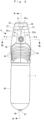
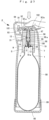
- [Fig. 1]
- is a perspective view of a piercing device attached to the gas cylinder and does not form part of the invention.
- [Fig. 2]
- is a front view of
Fig. 1 showing a state in which the seat belt is cut. - [Fig. 3]
- is a left side view of
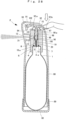
Fig. 1 . - [Fig. 4]
- is a sectional view taken along the line A-A of
Fig. 3 showing a state of pulling up the tab. - [Fig. 5]
- is a sectional view taken along the line B-B of
Fig. 3 . - [Fig. 6]
- is an exploded perspective view showing parts of an embodiment not forming part of the invention.
- [Fig. 7]
- is an enlarged longitudinal-sectional view of the cylinder holder, which is applied to an embodiment not forming part of the invention.
- [Fig. 8]
- is an enlarged longitudinal-sectional view of the piercing pipe, which is applied to an embodiment not forming part of the invention.
- [Fig. 9]
- is an enlarged sectional view showing the state of installing a hammer, which is applied to an embodiment not forming part of the invention.
- [Fig. 10]
- is a perspective view showing the reversed hammer, which is applied to an embodiment not forming part of the invention.
- [Fig. 11]
- shows a state in which a windshield of a car is broken from inside by the hammer which is applied to an embodiment not forming part of the invention.
- [Fig. 12]
- is a sectional view of an embodiment showing a state in which after the safety member is pulled out and does not form part of the invention.
- [Fig. 13]
- is a sectional view of an embodiment showing that the piercing member is pushed down for the seal piercing after the safety member is pulled out and does not form part of the invention.
- [Fig. 14]
- is a sectional view of an embodiment showing that the extinguishing gas is jetted outside by pushing down the piercing member after the seal is pierced and does not form part of the invention.
- [Fig. 15]
- shows an embodiment not forming part of the invention and is a sectional view of of the hammer. In (a), the hammer is attached by gluing. (b) shows a state in which the hammer is insert molded with the cylinder cover and the cover is attached to the gas cylinder.
- [Fig. 16]
- is a front view of the embodiment of the invention showing that the other embodiments of the seat belt introduction groove and the hammer.
- [Fig. 17]
- is an enlarged sectional view of the embodiment of the invention showing a state before piercing the seal and a situation in which the seat belt introduction groove and the cutter is attached.
- [Fig. 18]
- is an enlarged sectional view of the embodiment of the invention showing a state in which the seal is pierced.
- [Fig. 19]
- is a sectional view of the
Fig. 16 taken along the line of C-C showing enlarged seat belt releasing part applied to the embodiment of the invention. - [Fig. 20]
- is an enlarged illustration of an operation of cutting the seat belt by the seat belt releasing part.
- [Fig. 21]
- is an enlarged sectional view of a main part of the hammer applied to the embodiment of the invention.
- [Fig. 22]
- is a perspective view showing a state in which the storing case applied to the embodiment of the invention is installed in a car.
- [Fig. 23]
- is a perspective view showing the protective case applied to an embodiment of the present invention. It shows the piercing device and the protective case before the piercing device is stored.
- [Fig. 24]
- is a perspective view of the protective case applied to an embodiment of the invention showing a state in which the piercing device is stored.
- [Fig. 25]
- is a right side view of
Fig 24 . - [Fig. 26]
- is a sectional view of the fire extinguisher gas ejector applied to an embodiment not forming part of the invention showing a state in which before the seal is pierced.
- [Fig. 27]
- is a sectional view of an embodiment not forming part of the invention showing a state in which the seal is pierced.
- [Fig. 28]
- shows a state in which the extinguishing gas is jetted from the nozzle hole by operating the piercing member after the seal piercing of an embodiment not forming part of the invention.
-
- 1
- gas cylinder
- 2
- piercing device
- 5
- cylinder holder (inner pipe)
- 6
- outer shell (outer pipe)
- 8
- through hole
- 10
- piecing pipe
- 14
- nozzle hole
- 19a
- tip part
- 22
- piercing member (piercing knob)
- 24
- tab
- 27
- safety member (safety plate)
- 35
- seat belt
- 36
- sea belt introduction groove
- 37
- cutter
- 37
- edge of the cutter
- 42,43
- curved concaved parts
- 44
- concaved part
- 45
- convex part
- 47
- hammer
- 48, 72
- pointed part
- 52
- seat belt releasing part
- 55
- seat belt releasing surface
- 66
- retaining ring
- 67
- hammer shaft
- 71
- neck part (annular groove)
- 75
- storing case
- 79
- stopper
- 80
- strap
- 84
- protective case
- 85
- upper opening
- 86
- lower opening
- 92
- seal piercing member (lever)
- 96
- valve hole
- 98
- control valve
- 99,100
- O-ring
- The following is description of illustrated embodiments that this invention is applied to a fire extinguisher gas ejector for in-car use which uses a cartridge gas cylinder. In
Fig. 1 to 14 ,reference numeral 1 represents a known and small gas cylinder which is charged with carbon dioxide as an extinguishing gas. The gas cylinder ofFig. 1 to 14 does not form part of the invention. A mouth part of thegas cylinder 1 is provided with a piercingdevice 2. - The
gas cylinder 1 ofFigures 1 to 14 requires about 40 mm in external diameter, about 130 mm in length, and about 90 ml in tare weight and is charged with carbon dioxide of about 4MPa therein. The weight after charging is about 300g. After charging the gas, the mouth part is sealed with the sealingplate 3 and a hammer, which is described later, is attached to a bottom. - A
thread part 4 is formed on a periphery of the mouth part for thegas cylinder 1 and is screwed to the piercingdevice 2 to be fixed. - The
seal piercing device 2 is formed in a shape of an irregular tubular with strong and light synthetic resin. Theseal piercing device 2 is composed of double pipes. One is acylinder holder 5 which has a lower end capable of screwing thethread part 4. The other is anouter pipe 6, outer shell, which has a hollow tubular shape and is arranged outside of thecylinder holder 5. - Of them, the
cylinder holder 5 is formed in shape of virtually cylindrical with aluminum and has ascrew hole 7 at the lower end capable of screwing thethread part 4.
Thecylinder holder 5 has a throughhole 8 which communicates with thescrew hole 7 and ahole 9 which is a little smaller than the throughhole 8 therein to communicate each other in the coaxial direction. Theseal piercing pipe 10, which will be described later, is inserted slidably the throughhole 8 and thehole 9. - In the illustration,
reference numerals ring 11 is inserted in a step of dividing part between the throughhole 8 and thehole 9. The O-ring 12 is inserted in a annular groove between thescrew hole 7 and the throughhole 8. - The middle to upper periphery of the
cylinder holder 5 has a jettingport 13 which constitutes a jetting flow path together with the throughhole 8 and a nozzle hole, which will be described later. Anozzle hole 14, which communicates with the throughhole 8, is formed in the inner part of the jettingport 13. - A pair of positioning pins 15 is protruded from the outer periphery of the
cylinder holder 5 to the diameter direction and thepins 15 are fitted to the pin holes that are formed on inner surfaces of outer pipe pieces, which will be described later. Outer pipe pieces 6a, 6b are connected to predetermined positions to prevent dislocation of guide holes 31a, 31b, connecting surfaces 38a, 38b, and recessed grooves 38a, 38b. - A pair of recess holes 16 are formed at the positions of 90 degree from the jetting
port 13 on the periphery of thecylinder holder 5. The positioning pins 15 are pressed in the recess holes 16 and the ends are protruded from the periphery. - The piercing
pipe 10 is formed in a shape of bar by processing aluminum bar. The upper half of the piercingpipe 10 is slidably inserted to thehole 9 and a large-diameter part 10a is formed on the middle part. The large-diameter part 10a is slidably inserted to the throughhole 8. In drawings,reference numeral 17 is an annular groove formed on the large-diameter part 10a.Reference numeral 18, which is an O-ring, is attached to theannular groove 17. - A
needle tube 19, which is made of steel tube, is fixed to the lower end of theseal piercing pipe 10 and the end of 19 is diagonally cut permitting the tip part 19a to pierce the sealingplate 3. - In this case, without providing the
seal piercing pipe 10 and theneedle tube 19 separately, these parts can be integrally constituted. Then, a number of parts are reduced and the structure becomes simpler. Accordingly, the piercingpipe 10 only has to be equipped with the tip part 19a at one end. - In drawings,
reference numeral 20 represents a spring which is inserted between the end of the piercingpipe 10 and the sealingplate 3, and biased the piercingpipe 10 to move upwardly with the resilience. - The piercing
pipe 10 has a contractedsquare shank 21 at upper end. Thesquare shank 21 is fitted to a square hole 22a which is formed on the bottom surface of aseal piercing knob 22, which is the seal piercing member, and they are fixed together by using adhesive. In this case, instead of using adhesive on thesquare shank 21 and the square hole 22a, it is possible to fix them by screwing from the top of theseal piercing knob 22 or using a retaining ring. - The
seal piercing knob 22 is formed in a shape of virtually elliptical plate with synthetic resins, on which the top surface is gently recessed so as to be able to put a finger. A chevron-shapedrib 23 is projected on the front peripheral edge and a knob of atab 24 is arranged overlapped on the base side of therib 23. - The
tab 24 is formed by bending the synthetic resin rod, which has the same quality as of the piercingdevice 2, into a shape of virtually triangular, and the knob 24a is formed by bending the apex diagonally upward. - Then, the knob 24a is disposed on the middle part of top surface of the
seal piercing knob 22 to be able to put thefinger 25 thereon. The knob 24a can be pulled up with a connectingpart 26, which protruded from back end, as a fulcrum. - The connecting
part 26 is formed diagonally downward, with the lower end connected to the rear end of thesafety plate 27. - The
safety plate 27 is formed with the same member as thetab 24 and is shaped in an elliptical plate, which is little larger than thetab 24. - The
notch 28 is formed in the front-back direction on the half front of asafety plate 27, and anotch 28 is engaged with upper part of theseal piercing pipe 10. - Specifically, the
safety plate 27 is usually inserted between theseal piercing knob 22 and the upper surface of theouter pipe 6. The piercingpipe 10 is engaged with thenotch 28 to prevent pulling out thesafety plate 27 and pressing theseal piercing tab 24. When thetab 24 is raised and pulled up, thesafety plate 27 can be pulled backwardly along thenotch 28. - On the other hand, the
outer pipe 6 is constituted with two pieces that are split in the axial direction along a jetting port guide, which will be described later, and thecylinder holder 5 is stored therein. Connecting surfaces 29a, 29b, are integrally attached as one with heat welding. In such a case, the outer pipe pieces 6a, 6b can be joined together by screwing or using adhesive instead of heat welding. - Irregular-shaped engaging holes 30a, 30b capable of storing the
cylinder holder 5 are symmetrically formed on the connecting surfaces 29a, 29b of the outer pipe pieces 6a, 6b. One side of the connecting surfaces 29a, 29b have guide holes 31a, 32b that constitute a funnel-likejetting port guide 31. - In illustrations, reference numerals 32a, 32b represent pin holes that are formed on the inner surfaces of the engaging holes 30a, 30b permitting the
positioning pin - A chevron-shaped
protrusion 33 is formed in the axial direction on the back periphery of theouter pipe 6, and aseat belt guide 34 is protruded outside of theprotrusion 33 obliquely downward from the upper end of theouter pipe 6, virtually parallel with theprotrusion 33. - A seat
belt introduction groove 36 capable of inserting aseat belt 35 is formed between theseat belt guide 34 and theprotrusion 33, facing the inner surface of theintroduction groove 36 each other. - A
cutter 37 is arranged at upper part of theintroduction groove 36. An edge of the cutter 37a is vertically arranged, and acutely arranged with respect to the direction of introducing theseat belt 35. Theseat belt 35 can be cut at sharp angle with respect to a direction of the thickness of theseat belt 35. - The
seat belt guide 34 is constituted by joining guide pieces 34a, 34b that extend from outer pipe pieces 6a, 6b. Concaved grooves 39a, 39b, that are virtually parallelogram shape, are formed in axial direction over the joining surfaces 38a, 38b and the connecting surfaces of 29a, 29b of the outer pipe pieces 6a, 6b. Thecutter 37 is stored in the concaved groove 39a, 39b. - In illustrations, a
pin 40 protrudes from the recessed grooves 39a, 39b are inserted in afitting hole 41 formed on thecutter 37 to prevent displacement. - The
outer pipe 6 has lower periphery on which the front and back sides are concavely curved, and the cross sectional view is an elliptical shape. Curvedconcaved parts concave part 44 and aconvex part 45 that form curved patterns for to make friction so that the part can easily or firmly grasped. - The
outer pipe 6 has skirt-like peripheries on lower part and the skirt-portions are arranged apart at the outside of the periphery of the shoulder part. These spaces block heat conduction, which lowers a temperature of the surface of thegas cylinder 1 when the extinguishing gas is jetted. Thus, the temperature drop of the curvedconcaved parts - The
gas cylinder 1 has asheet 46 made of heat insulating film on the middle periphery with printed pictures thereon that show how to use of the fire extinguisher gas ejector. The heat insulation action is obtained when putting out a fire. - The film made of synthetic resin is used for the
sheet 46, the film is attached by shrinking with predetermined temperature on the surface of thegas cylinder 1 which is filled with carbon dioxide. - The
hammer 47 having the pointed part is attached to the exposed bottom of thegas cylinder 1, and ahammer 47 is molded by sintering to a predetermined hardness with a prescribed powder metal. - The
hammer 47 is shaped in a thin, concavely or convexly curved plate capable of contacting the bottom of thegas cylinder 1. A pointedpart 48, which is a cone shape, is protruded from the center of the convex surface side. - After molding to the predetermined shape with sintering, the
hammer 47 is prepared to high hardness by quenching with the predetermined temperature. Theprepared hammer 47 is attached to the bottom of thegas cylinder 1, which is filled with carbon dioxide, by spot welding or welding. - Accordingly, the
hammer 47 can be attached to thegas cylinder 1 smoothly and safely without changing a conventional process or filling facility of carbon dioxide for thegas cylinder 1. - In this case, the
hammer 47 can also be attached by bonding or brazing instead of spot welding. A thick steel plate is press molded to said shape instead of molding thehammer 47 with sintering, and the hammer can also be attached by spot welding, welding, bonding, or soldering. - In illustration,
reference numeral 49 shows the extinguishing gas jetting for outside from the jettingport guide 31 after the seal is pierced.Reference numeral 50 shows a windshield of a car. - The fire extinguisher gas ejector, which is constituted by the way above, is constructed by attaching the piercing
device 2 on top of the small gas cylinder. Thesmall gas cylinder 1 is constituted by attaching thehammer 47 for an emergency escape. The piercingdevice 2 is constituted with the piercingpipe 10, the piercingknob 22, thesafety plate 27 which is integrally formed with thetab 24, and thecutter 37 for cutting a seat belt for escaping in case of an emergency. - When making a fire extinguisher gas ejector, the
hammer 47 is molded by sintering. After the sintering, thehammer 47 is prepared for predetermined hardness and is attached to the bottom of thesmall gas cylinder 1 by spot welding. - The piercing
device 2 is produced by combining following parts. The resin molded outer pipes 6a, 6b, the piercingknob 22 and thetab 24 that are respectively resin molded, and thecylinder holder 5, the piercingpipe 10, and thecutter 37 that are metal processed. - Then, when making the
hammer 47 firstly, prescribed powder metal is molded by sintering and shape it into concavely or convexly curved thin plate. Then, the conically shaped pointedpart 48 is protruded on the center of the convex surface side. - This state is shown in the
Fig. 10 . After the molding, thepointed part 48 is prepared for high hardness by quenching with a predetermined temperature. - When attaching the
hammer 47, which is produced by the way above, to thegas cylinder 1, thehammer 47 is spot welded to thegas cylinder 1 which is filled with the extinguishing gas, carbon dioxide, and sealed with the sealingplate 3. - The spot welding is carried out by connecting the concavely curved surface of the
hammer 47 with the bottom of thegas cylinder 1, energizing, and welding. The state is shown in theFig. 9 . - In this case, the spot welding temporarily causes high temperature. However, the filled carbon dioxide has no risk for an ignition, explosion, or a sudden expansion. After the spot welding, the current state is promptly recovered so that the operation of spot welding is performed safely.
- Moreover, there is no risk for a deformation due to thermal stress of the spot welding or a crack due to a distortion. Therefore, the strength of the
gas cylinder 1 is remained, and the state of the filled carbon dioxide remains the same. - The sealing
plate 3 is also sealed by spot welding after filling the carbon dioxide. This suggests that it is safe to carry out a spot welding to thegas cylinder 1. - Moreover, the spot welding to the
gas cylinder 1 is carried out after the carbon dioxide is filled. Therefore, filling operation of the carbon dioxide can be carried out in a conventional manner by using filling facilities that already exist. It will not reduce the productivity and the efficiency. - Accordingly, decrease of safety or productivity can be avoided unlike a case in which the spot welding is carried out before filling carbon dioxide, which affects the use of the conventional facilities of filling by the spot welded
hammer 47 or causes decrease of efficiency and productivity due to changes of operations. - In this case, it is also possible to attach the
hammer 47 to the filledgas cylinder 1 by bonding or brazing instead of spot welding. - Of them, bonding does not require any special facility for attachment. Little consideration needs to be given to effects of temperature of spot welding and thermal stress on the filled gas.
- Moreover, brazing requires lower temperature compared to spot welding. It reduces effects of temperature of brazing on filled gas and thermal stress. At the same time, similar advantages and strength can be obtained as spot welding.
- Meanwhile, a thick steel plate is press molded into the above-mentioned shape and it can also be attached by spot welding, bonding or brazing instead of molding the
hammer 47 with sintering. - The way above does not require an expensive facility for sintering and molding and simple and low cost production is possible by the press molding.
- After the
hammer 47 is attached, thesheet 46 is attached on the middle periphery of thegas cylinder 1. - A film made of synthetic resin is used for the
sheet 46 with printed pictures that show usage of the fire extinguisher gas ejector. Then, the film is cut to a predetermined size and formed in shape of roll. The periphery of thegas cylinder 1 is covered with the sheet, and then, shift it into a heat furnace with predetermined temperature for heat contraction. The shrunk film is attached on the middle periphery of thegas cylinder 1. - Next, when producing the piercing
device 2, the outer pipe pieces 6a, 6b, the piercingknob 22, and thesafety plate 27 are separately resin molded, thecylinder holder 5 and the piercingpipe 10 are machine processed with different diameter aluminum bars, and thecutter 37 is produced by press molding the steel plate. - Of them, outer pipe pieces 6a, 6b are formed by cutting axially the
outer pipe 6 into half at the position of the jettingport guide 31. And the center of the connecting surfaces 29a, 29b of the cylinder body side have the engaging holes 30a, 30b and the engaging holes 30a, 30b have the pin holes 32a, 32b on the middle. - Furthermore, one sides of the connecting surface 29a, 29b have the guide holes 31a, 31b that constitute the jetting
port guide 31. The concaved grooves 39a, 39b that store thecutter 37 are formed on the other sides. - On the other hand, the guide pieces 34a, 34b are integrally protruded from the outside of the cylindrical body side. A part of the concaved grooves 39a, 39b is formed on the connecting surfaces 38a, 38b.
- Moreover, the curved
concaved parts concaved part 42 of front side has a plurality of theconcaved parts 44, theconcaved part 43 of back side has a plurality of theconvex parts 45. - The
seal piercing knob 22 is shaped in an elliptical plate which has longer major axis in front and back and the top surface is gently concaved and curved. The chevron-shapedrib 23 is protruded from the front side and square hole 22a is disposed on the lower surface. - The
safety plate 27 and thetab 24 are integrally formed. Of them, thesafety plate 27 and theseal piercing knob 22 are shaped in virtually the same elliptical plate, and thenotch 28 is disposed on the front side. - The
tab 24 is formed in a shape of regular triangular by using a flat bar and the knob 24a is formed by turning up the front obliquely upward. The rear of the knob 24a is connected to the back of thesafety plate 27 by the connectingpart 26, which protruded obliquely downward. - The
cylinder holder 5 is formed cylindrical in which the throughhole 8 and thehole 9 are formed therein. The holes are smooth and have different diameters. The lower part of thecylinder 5 has thescrew hole 7, and the jettingport guide 13 and thenozzle hole 14 that are disposed on the middle circumference are communicating with the throughhole 8. - A pair of recessed
holes 16 is disposed diametrically on the surface of the circumference of thecylinder holder 5. Thepins recess hole 16. - The
seal piercing pipe 10 is formed in a bar shape, the large-diameter part 10a and theannular groove 17 are disposed on the middle, and thesquare shaft 21 are formed on the top end. One end of a steel pipe is obliquely cut to make theneedle tube 19, one end of thetube 19 is pressed into lower end of the piercingpipe 10, and the tip part 19a is protruded outside. - In this case, the
needle tube 19 can be omitted if the piercingpipe 10 is integrally provided with the tip part 19a. - Moreover, the
cutter 37 is produced by press molding a steel plate, and thefitting hole 41 is disposed on the middle, and the edge of the cutter 37a is disposed on the side edge. - After the parts above are produced, the piercing
device 2 is produced by assembling them. - For assembly, the engaging hole 30a of the outer pipe piece 6a is stored in the
cylinder holder 5, thepositioning pin 15 is inserted to the recess hole 32a, thecutter 37 is stored in the recessed groove 39a, and thefitting hole 41 is inserted to thepin 40. - Then, the connecting surface 29a of the other outer pipe piece 6b is joined with the connecting surface 29a, the
positioning pin 15 is inserted into the recess hole 32b of the engaging hole 30b, and after the connecting surfaces 29a, 29b are attached, the outer pipe pieces 6a, 6b are connected together. - When heat welding is used for the connection, an electrical heat plate (not shown) is inserted between the connecting surfaces 29a, 29b. Then, applying current to the electrical heat plate and heated to a melting temperature. After the connecting surfaces 29a, 29b are melted, the electrical heat plate is pulled out, connecting surfaces 29a, 29b are welded, and the
cutter 37 and thecylinder holder 5 are integrally buried therein. - In this case, when adhesion is used for connection, adhesive material is applied to the connecting surfaces 29a, 29b. When screwing is used for the connection, screw holes are previously disposed at corresponding positions of the outer pipe pieces 6a, 6b and connect them together by screwing.
- The piercing
pipe 10 is inserted from the lower side of the throughhole 8 of thecylinder holder 5 of the connectedouter pipe 6. The top end of thesquare shaft 21 is protruded from thehole 9, the square hole 22a of theseal piercing knob 22 is fitted into thesquare shaft 21 with therib 23 facing front, and they are connected together and fixed. - In this case, instead of the attachment above, the
square shaft 21 and theseal piercing knob 22 can be fixed by screwing or can be attached with a retaining ring. - After the piercing
knob 22 is mounted on thesquare shaft 21, thesafety plate 27 is inserted therebetween. Thenotch 28 is inserted to the top of the piercingpipe 10 with thesafety plate 27 sandwiched, and the assembly of the piercingdevice 2 is completed when thetab 24 integrally formed with thesafety plate 27 is attached on theseal piercing knob 22. - As for shape, assembled piercing
device 2 is composed about 83 mm high, about 60 mm long in front-back direction, and about 43 mm in external diameter. When thegas cylinder 1 is loaded to the piercingdevice 2 which thehammer 47 is already attached thereto, thespring 20 is inserted to the throughhole 8 of thecylinder holder 5 of the piercingdevice 2, O-ring 12 is attached to a step between the throughhole 8 and thescrew hole 7, and thethread part 4 of thegas cylinder 1 is screwed to thescrew hole 7. - The fire extinguisher gas ejector, which loaded the
gas cylinder 1, is shown in theFig. 1 to Fig. 3 and is constituted small and lightweight, 183 mm high and weigh 460g. Unlike conventional ones, it does not require a case that covers the outside of thegas cylinder 1 so that the constitution becomes simpler and lightweight. Accordingly, it can be produced easily and at low cost. - Moreover, the
cutter 37 and thehammer 47 are provided with thegas cylinder 1 and piercingdevice 2, essential components for the fire extinguisher gas ejector. It does not require an exclusive device for escaping so that the mechanisms for fire extinguishing and escaping are constituted rationally. As for advantages, these functions can be used simply. - The assembled fire extinguisher gas ejector has the
tab 24 with the knob 24a raised and exposed on theseal piercing knob 22, and thesafety plate 27 integrally formed with thetab 24 is located between theseal piercing knob 22 and theouter pipe 6. - The jetting
port guide 31 is located at middle and high position on front of theouter pipe 6, theseat belt guide 34 is protruded obliquely downward, and the edge 37a of thecutter 37 is perpendicularly disposed in the upper seatbelt introduction groove 36. - The curved
concaved parts port guide 31 and theseat belt guide 34. The upper part of thegas cylinder 1 is located inside of theconcaved parts - The mouth part for the
gas cylinder 1 is sealed with the sealingplate 3 as shown inFig. 4 , the piercingpipe 10 is located immediately above the sealingplate 3 to be able to move up-and-down, the piercingpipe 10 is biased upwardly to move with the resilience of thespring 20 and the tip part 19a of theneedle tube 19 is located immediately above the sealingplate 3. - The
sheet 46 is attached to cover the middle periphery of thecylinder 1, thehammer 47 is disposed to the bottom of thecylinder 1, and thepointed part 48 is downwardly exposed. In this case, it is preferable that a suitable cover is removably attached on thepointed part 48. - When installing such fire extinguisher gas ejector on a car, it is stored transversely or longitudinally around a driver seat, front seat, a pocket of inner side of a door or an accessory case, which is around a shift lever.
- In this case, a cross sectional view of the piercing
device 2 is formed in a shape of elliptical which has a major axis in front and back direction so that rolling motion, abnormal noise and damage of fire extinguisher gas ejector can be prevented when it is put transversely. - In that case, if an appropriate holder is mounted to said position in a car to fix the fire extinguisher gas ejector, further stability can be obtained.
- When the device is installed on a car and if the
seat belt 35 cannot be taken off or/and a door does not open by a traffic accident, theseat belt 35 need to be cut and/or awindshield 50 needs to be broken when a driver or other member evacuate outside of the car. - Of them, when cutting the
seat belt 35, the curvedconcaved parts belt introduction groove 36 of the piercingdevice 2 front, theseat belt 35 is inserted into the seatbelt introduction groove 36 to contact the edge 37a of thecutter 37, and the piercingdevice 2 is pulled down to slice through theseat belt 35. The state is shown in theFig. 2 . - In this case, the seat
belt introduction groove 36 is obliquely and downwardly open with respect to the axial direction of the piercingdevice 2 so that theseat belt 35 can be smoothly inserted by the chevron-shapedprotrusion 33 compared to a one which has a groove opens perpendicularly and downwardly. - Moreover, the edge 37a of the
cutter 37 is disposed at an acute angle with respect to the introduction direction of theseat belt 35. The edge 37a of thecutter 37 cuts into the side edge of theseat belt 35 and prompt smooth cutting, compared to a edge of a cutter is disposed at right angle with respect to the seat belt introduction groove. - When breaking the
windshield 50, the fire extinguisher gas ejector is grasped with the bottom pointing a car side window or windshield, as with the case cutting theseat belt 35. Then, awindshield 50 is smashed with thepointed part 48 of thehammer 47 by smashing and striking thewindshield 50. This state is shown inFig. 11 . - In this case, when breaking the
windshield 50 after theseatbelt 35 is cut, thewindshield 50 can be broken in continuous motion without shifting the fire extinguisher gas ejector. Similarly, when cutting theseat belt 35 after breaking thewindshield 50, theseat belt 35 can be cut in continuous motion without shifting a fire extinguisher gas ejector. - Accordingly, the action can be carried out quickly and safely compared with the one, which dispose the seat
belt introduction groove 36 and thehammer 47 at the same side or different position. - Moreover, the
hammer 47 is disposed apart from the seatbelt introduction groove 36 so that thewindshield 50 is smashed surely and there is no fear of being injured. - Neither the operation nor impact of cutting the
seat belt 35 and breaking the windshield would separate thesafety plate 27 from the fixed position. The movement of the piercingpipe 10 is prevented so there is no fear of seal piercing accidentally. - Next, explanations for the fire extinguisher gas ejector are described below.
- Specifically, if a fire occurs and it is extinguished when the fire extinguisher gas ejector is installed in a car, hold the fire extinguisher gas ejector with one hand, and put the
finger 25 on the knob 24a of thetab 24 and pull up. The state is shown inFig. 4 . - In this case, the
tab 24 is configured the same as a known tab for opening a beverage container so that an operation for pulling the knob 24a up is easily understandable. It is possible to respond to a fire in a car, which needs quick operations. - Thus, when the knob 24a of the
tab 24 is raised, thetab 24 is pulled up with therear connecting part 26, as a fulcrum, against resilience. The component force for backward acts on thesafety plate 27, which is integrally formed with thetab 24 through connectingpart 26. - Therefore, the
safety plate 27 is moved backward against the engaging force of the piercingpipe 10 and thenotch 28, and thesafety plate 27 is pulled out backwardly. - The state is show in
Fig. 12 . The top surface of theseal piercing knob 22 is exposed, and a space, which is the same thickness as thesafety plate 27, is formed between theseal piercing knob 22 and the top edge of theouter pipe 6. - Then, the fire extinguisher gas ejector is shifted to grasp the curved
concaved parts device 2 as shown inFig. 12 . Then, thefinger 25 is put on the top of theseal piercing knob 22 and press down theseal piercing knob 22. - In this way, the piercing
knob 22 is descended against the resilience of thespring 20, which moves the piercingpipe 10 accordingly, and the tip part 19a of theneedle tube 19 pierces the sealingplate 3. The state is shown inFig. 13 . - This introduces the filled gas of the
gas cylinder 1 to jet from the pierced point to theneedle tube 19, and the pressure acts on theneedle tube 19 and the piercingpipe 10. Consequently, the jetting pressure thrusts back the piercingpipe 10 and the top end of the large diameter part 10a is contacted with thestep 11 and returned to the original position to stop. - The state is shown in
Fig. 14 . Theneedle tube 19 is moved immediately above the sealingplate 3, the pierced point of the sealingplate 3 is communicated with the throughhole 8, and the throughhole 8 is communicated with thenozzle hole 14 and the jettingport 13. - Accordingly, the filled gas is jetted from a pierced hole to the through
hole 8 and it is introduced from thenozzle hole 14 to the jettingport 13. Then, the gas is jetted outside from the jettingport guide 31 and sprayed onto the source of the fire.
At this time, a part of the carbon dioxide is adiabatically expanded to become dry ice after jetting the filled gas and it is mixed with the gaseous carbon dioxide and jetted toward the origin of a fire. - Thus, it lowers a temperature around a fire origin and stops oxygen supply. It promotes efficiency and quick fire extinction.
- At this time, when the carbon dioxide is jetted, the latent heat cools and absorbs the heat of the surface of the
gas cylinder 1. The skirt part, which is close to thecylinder 1 and lower side of the piercingdevice 2, prevents heat conduction by a space disposed inner side so that thefinger 25 is not affected. - The fire extinction continues until all the filled gas is completely used so that the filled gas can be effectively used. Thus, the effectiveness of the fire extinction is increased.
- Moreover, after the filled gas is used up, the
empty gas cylinder 1 can be easily recovered after detaching thegas cylinder 1 from thescrew hole 7 of thecylinder holder 5. -
Fig. 15 to Fig. 28 shows other embodiments some forming part of the present invention and others not forming part of the present invention, and identical numerals are used for the parts that have the same constitution with the above-mentioned embodiment. - Of them,
Fig. 15 is an embodiment not forming part of the present invention showing thehammer 47. - Specifically, in
Fig. 15 (a) , thehammer 47 which is made from sintered metal or press molded steel plate is attached to the bottom of thegas cylinder 1 to alleviate a concern over strength reduction of thegas cylinder 1 due to thermal stress by heating of spot welding and brazing. - In
Fig. 15 (b) , thehammer 47 is insert molded by use of a bowl-shapedplastic cylinder cover 51. Thecover 51 is attached to the exposed bottom of thegas cylinder 1 so that thecover 51 is rigidly attached. -
Fig. 16 to Fig. 22 is the embodiment of the present invention showing other cutting form of theseat belt 35, the other form of thehammer 47, and installed form of the fire extinguisher gas ejector in a car. - Of them, as for other cutting form of the
seat belt 35, the edge 37a of thecutter 37 is disposed obliquely downward in the middle of the seatbelt introduction groove 36, and a seatbelt releasing part 52 is disposed with a space at the rear of thecutter 37. - The seat
belt releasing part 52 is integrally formed with the joiningpart 53, which is disposed back of the seatbelt introduction groove 36. The joiningpart 53 is constituted by attaching a pair of joining pieces 53a, 53b that connect theseat belt guide 34 and theouter pipe 6, and the seatbelt releasing part 52 is protruded adjacent to theneck portion 54 of the joiningpart 53. - The seat
belt releasing part 52 is constituted by connecting a pair of seat belt releasing part pieces 52a, 52b. The cross sectional view has a shape of inverted triangular, which the width increases as it goes to the back of the seatbelt introduction groove 36 from the distal end, the seatbelt releasing part 52 has wider width except the distal end than the thickness of thecutter 37, and the periphery which curves outside forms the seatbelt releasing surface 55. In illustration,reference numeral 56 indicates a space between thecutter 37 and the seatbelt releasing part 52. - In this embodiment of the invention, the
cylinder holder 5 is formed by aluminum and has the throughhole 8 therein, which communicates with thenozzle hole 14. Thecylinder holder 5 is buried in theinner pipe cover 57, which is made of synthetic resin, as a insert fixture to make them integrated. The jettingport 13 and the jettingport guide 31 are formed on theinner pipe cover 57, and theouter pipe 6 is disposed outside of theinner pipe cover 57. - Upper part of the
outer pipe 6 has a pair of guide holes 58, and theguide pin 59, which is integrated with theseal piercing knob 22, is slidably inserted to theguide hole 58. Theseal piercing knob 22 has a flat surface top and arecess hole 60 on the center. The threadedshaft 61 which is provided on the top end of theseal piercing pipe 10 is disposed in therecess hole 60, and theseal piercing knob 22 is attached to the piercingpipe 10 by screwing thenut 62 into the threadedshaft 61. - The
spring 63 which is inserted between the top end surface of theinner pipe cover 57 and a flanged part of the upper end of the piercingpipe 10 is used as a substitute of thespring 20 which is disposed around theneedle tube 19. The resilience of thespring 63 biased theseal piercing knob 22 upwardly. In illustration,reference numeral 64 shows a cap, which closes therecess hole 60. - The
tab 24 of the embodiment of the invention is disposed immediately above the end of theseal piercing knob 22 with the knob 24a extended. Thesafety member 27, which is integrally formed with thetab 24, is formed in a shape of a ring from a plate. This arrangement promotes the operation of pulling thetab 24 up withnotches safety member 27 out. -
Fig. 17 shows the statement of the embodiment of the invention in which before the seal is pierced. Thespring 63 biased theseal piercing knob 22 upwardly, intervening thesafety member 27 just under theseal piercing knob 22. Thetab 24 is located immediate above theseal piercing knob 22 and thetab 24 is normally restrained to theseal piercing knob 22 with an adhesive seal (not shown). - When piercing the seal, the adhesive seal is broken, and the knob 24a of the
tab 24 is held to pull up and moved toward upper right inFig. 17 . Then theseal piercing knob 22 is pulled out and make a space just under theseal piercing knob 22. - Then, the piercing
knob 22 is pressed down against thespring 63 and the piercingpipe 10 is pressed down, and it moves theneedle tube 19 in accordance with the move of the piercingpipe 10. The sealingplate 3 is pierced with the tip part 19a of theneedle tube 19. The state is shown inFig. 18 . - After the seal is pierced, the extinguishing gas in the
gas cylinder 1 is jetted out, pushing up the piercingpipe 10 by the extinguishing gas through theneedle tube 19. The gas comes to the throughhole 8, then the gas is introduced from thenozzle hole 14 to the jettingport guide 31 and is jetted outside. - On the other hand, in this embodiment of the invention, when cutting the
seat belt 35, as mentioned above, the curvedconcaved parts belt introduction groove 36 front, theseat belt 35 is held with another hand and inserted into the seatbelt introduction groove 36 - Then, a side of the
seat belt 35 is contacted with the edge 37a of thecutter 37, and the piercingdevice 2 is pulled down quickly to slice through theseat belt 35. - The state is shown in
Fig. 20 . Firstly, the side of theseat belt 35 is cut through with the edge 37a of thecutter 37, and then the cut part is split in two sides along with thecutter 37 and moved to the back of the seatbelt introduction groove 36. - Then, after the cut part passes through the
space 56, the cutting pressure of thecutter 37 and the internal stress are released, then, the fiber is recovered and is moved to the distal end of the seatbelt releasing part 52. - After this, the cut part is divided from the distal end and is moved to the back along with the both sides of the
belt releasing surface 55, push opening the cut part. The spreading function reaches the other side of theseat belt 35, that is the cutting part side. It prevents theseat belt 35 and thecutter 37 from contacting both sides closely or stagnating. It promotes theseat belt 35 to move to the back smoothly. - Thus, the
seat belt 35 moves smoothly without stagnation from the seatbelt releasing part 52 to the edge 37a of thecutter 37 and smooth and quick cutting is carried out by thecutter 37. - In this case, when the seat
belt releasing part 52 is closely located to thecutter 37 and theseat belt 35 is stuck in the minute space, the move of theseat belt 35 is stagnated and unable to cut the belt. Thespace 56 prevents the situation. -
Fig. 21 is an enlarged view of thehammer 47 that is applied to the embodiment of the invention. - The
hammer 47 of this embodiment of the invention is structured with thesteel retaining ring 66 and thehammer shaft 67 which quenched steel hard material. - The retaining
ring 66 is formed in a shape of plate and has thehole 68 in center. After the retainingring 66 is welded to the bottom of thegas cylinder 1, thehammer shaft 67 is inserted to thehole 68 together with the stopper, the C-ring 69. After the insertion, the taperedsurface 70, which is inner rim of thehole 68, is engaged with the C-ring 69 to attach thehammer shaft 67 closely. - The
hammer shaft 67 has a shape of axis which is longer than the height of the retainingring 66, theannular groove 71, the neck portion, is formed on the base, thepointed part 72 is formed at the end, and thepointed part 72 is protruded form outside of the retainingring 66. - The welding of the retaining
ring 66 is carried out after the carbon dioxide is charged to predetermined pressure and the mouth part is sealed with the sealingplate 3. After the welding of the retainingring 66, thegas cylinder 1 and the retainingring 66 are plated at the same time. - After that, an adhesive is applied to the periphery of the
hammer shaft 67, which is processed with quenching, and plating, the C-ring 69, which has elasticity and has a circular cross section is attached by squeezing to theannular groove 71. Thehammer shaft 67 is inserted to thehole 68 while the C-ring is pushed and shrunk. - After the insertion, the tapered
surface 70 of the inner rim of thehole 68 is engaged with the spherical surface of the C-ring 69 with the elasticity. The C-ring 69 is attached by pressure to the taperedsurface 70 so that the wedge effect is obtained. The adhesive is put in the gap among thegas cylinder 1, the C-ring 69, and thehammer shaft 67, and then fixed to attach thehammer shaft 67 stiffly and tightly. - In this case, the retaining
ting 66 is welded to thegas cylinder 1. The processes of welding and plating thehammer shaft 67 to thegas cylinder 1 are avoided by engaging thehammer shaft 67 to the retainingring 66. - Accordingly, when the
hammer shaft 67 is welded to thegas cylinder 1 and plated, it prevents the situation in which thepointed part 72 of thehammer shaft 67 damages the periphery of thegas cylinder 1. - As mentioned above, in this embodiment of the invention, conventional facilities are available for filling of the gas and for plating process. The
hammer 47 can be attached surely and safely without changing the procedures. - The
Fig. 22 shows the fire extinguisher gas ejector, which is installed in a car. - The storing
case 75 which is like a elongated shape bag and stores the piercingdevice 2 with thegas cylinder 1 is stored in theconcaved door pocket 74 which is provided with the inner side of adoor 73 adjacent to the driver's seat. - The storing
case 75 is made by sewing a plate of soft foamed polyurethane resin. It is structured with one end closed and the other end is open. The opening side has one end of the open-close belt 76, which is attached detachably. - One ends of attaching
belts case 75 and thesimple stopper 79 such as a hook is disposed at the other ends, and astopper 79 is removably attached to a stopper (not shown), such as a hook, which is buried outside wall of adoor pocket 74 to fix a storingcase 75 in place. - A
strap 80 is attached to the other ends of the attachingbelt strap 80 with one hand and pull up to remove the fixation of the stopper. Then the storingcase 75 is taken out from thedoor pocket 74. - After taking the storing
case 75 out, one end of opening and closingbelt 76 is undone, the piercingdevice 2 is taken out from thecase 75 to carry out an operation of fire extinguishing, cutting of theseat belt 35, and breaking awindshield 81. In illustration,reference numeral 82 shows a door trim and 83 shows a power window device. -
Fig. 23 to Fig. 25 shows an embodiment of the present invention. The embodiment shows a bottomedprotective case 84 for storing the piercingdevice 2 and the bottom of thecase 84 covers thehammer 47. For easy carrying and safety of the piercingdevice 2, it is installed, inside of a headrest and an appropriate place of a mat (not shown) to the fixed position by using a clip. - The
protective case 84 is shaped like a vertically long bag using light and soft resin foam. There is anupper opening 85 which is made by cutting the body obliquely, and theupper opening 85 stores theseal piercing knob 22, thetab 24, the knob 24a, theseat belt guide 34, seatbelt introduction groove 36, and thecutter 37, respectively exposed. - A
lower opening 86 is formed on the lower part of the other side of theupper opening 85 of theprotective case 84, with the periphery of thegas cylinder 1 located exposed from thelower opening 86. In illustration,reference numeral 87 shows a plurality of open holes that have different diameters formed around theupper opening 63. One of them is opened to correspond with the jettingguide 31. - In this case, when breaking the
windshield 50, the piercingdevice 2 is taken out from theprotective case 84 to carry out an operation. In that case, theupper opening 85, thelower opening 86, and theopen hole 87 loosen the contact or adhesion between theprotective case 84 against the piercingdevice 2 so that the piercingdevice 2 is taken out smoothly from theprotective case 84. -
Fig. 26 to Fig. 28 shows an embodiment not forming part of the present invention. In this embodiment not forming part of the invention, a waste of the extinguishing gas is prevented by stopping discharging the extinguishing gas, which is jetted from the gas cylinder after the seal is pierced. The gas can be jetted accurately toward a fire origin, and the effective use of the gas and initial fire fighting can be achieved. It shows the fire extinguisher gas ejector having the control valve for household use or in car use, which has simpler structure by reducing the number of the part. - In this embodiment not forming part of the invention,
reference numeral 88 shows a case, which has a shape of a virtually hollow tubular, made of synthetic resin. It is structured by joining a pair of cut cases that are formed by cutting the center in half in the longitudinal direction. The case has ascrew part 89 on the lower periphery and a bottomedcap 90 is attached thereto. - The
case 88 has anopening 91 at top end and an operatinglever 92, which is a piercing member, is attached to theopening 91 to rotate up and down. The operatinglever 92 is structured with a synthetic resin plate which has virtually the same width of theopening 91, one end has a protrudedpin 93 which is slidably inserted to along hole 94 formed on thecase 88, and the other end is protruded from outside rear of thecase 88. - In illustration, reference numeral 92a is an engaging convex portion, which protruded in the center of the undersurface of the operating
lever 92. It is disposed engageable to the top end of the control valve, which will be described later, and asafety pin 95 is inserted to the engaging convex portion 92a. Numeral 92b is a concaved finger grip portion, which is formed on the other end of the operatinglever 92 and protrudes backward from thecase 88. - The
safety pin 95 is inserted by penetrating the center of the operatinglever 92 and thecase 88. One end of the gasping portion (not shown), protrudes outside of thecase 88, making impossible to press the operatinglever 92 in normal times or to pierce the seal accidentally. When thesafety pin 95 is pulled out by pulling the grasping portion (not shown), an operation of pressing thelever 92 can be performed. - The
small gas cylinder 1 is stored inside of thecase 88, with the bottom stored in thecap 90. The periphery of thegas cylinder 1 is formed with thethread part 4 and thethread part 4 is attached to thescrew hole 7 of thecylinder holder 5 by screwing. - The
cylinder holder 5 is formed in a shape of cylinder by aluminum die-casting. There is an opening for thescrew hole 7 at the lower end and the throughhole 8, avalve hole 96, and ahole 97 are disposed to communicate one another at the upper part of thethread hole 7. The respective inner diameters are formed to become smaller. - The middle to upper periphery of the
cylinder holder 5 is provided with the jettingport 13, which communicates with the jettingport guide 31, formed on thecase 88, and the bottom of the jettingport 13 is disposed with thenozzle hole 14, which communicates thevalve hole 96. - The
control valve 98, which is integrally formed with the piercingpipe 10, is slidably inserted to thevalve hole 96, and the top end is disposed to appear on top of thecylinder holder 5. The top end is disposed engageable with the engaging convex portion 92a when it protrudes. - The
needle tube 19, which is a piercing member, is protruded from the lower end of thecontrol valve 98, with the tip part 19a disposed immediately above the sealingplate 3. In this case, tubular structure is not necessarily required for theneedle tube 19. - The
control valve 98 is formed in a shape of stepped bar, and at least a pair of O-rings valve hole 96 and thenozzle hole 14 to be air tightened by the O-rings - The
spring 20 is inserted between the lower end of thecontrol valve 98 and the sealingplate 3, and the resilience of thespring 20 biased thecontrol valve 98 upwardly. The stepped portion 98a, which is formed on the middle of thecontrol valve 98, is able to be engaged with the rim of the lower opening of thehole 97. - The
control valve 98 is, in normal times, able to close thenozzle hole 14 by positioning the O-ring 100, which is disposed lower side, at inner rim of thenozzle hole 14. When pressing theoperation lever 92 and piercing the sealingplate 3, thelong hole 94 controls the descending displacement of both the operatinglever 92 and thecontrol valve 98, and the O-ring 99, which is disposed upper side, is positioned at inner rim of thenozzle hole 14 to be able to close thenozzle hole 14. - Then, when jetting the extinguishing gas by pressing the
operation lever 92 after the piercing, the O-rings 99,100 are respectively positioned at inner rim of thenozzle hole 14, the lower O-ring 100 is positioned at the side of the throughhole 8, and thenozzle hole 14 is communicated with the throughhole 8 to be able to jet the extinguishing gas from thenozzle hole 14. - In illustration,
reference numeral 101 shows a concaved part formed on the top of thecylinder holder 5, and alever spring 102 is inserted between theconcaved part 101 and theopening lever 92. The resilience of thespring 102 biased the operatinglever 92 upwardly. Numeral 3a shows a sealed hole of the sealingplate 3. - In this embodiment not forming part of the invention, an outer housing, a piercing holder, a pin, and a pushrod, the parts to be disposed around the
cylinder holder 5 in a conventional fire extinguisher gas ejector are omitted. Only thecylinder holder 5 is disposed upside of thecase 88 so that the number of the parts are reduced and they are easily assembled. Thus, small and light structure and low cost of the fire extinguisher gas ejector can be achieved. - In addition, the
control valve 98 of this embodiment not forming part of the invention requires only to form the annular groove, which attaches two O-rings 99,100 at the predetermined position of the periphery of the piercingpipe 10. Compared to the conventional control valve, the structure is simpler and the less number of the parts is required. Therefore, it is produced easily and inexpensively. - The fire extinguisher gas ejector is used as follows. The
cap 90 is removed before use, thegas cylinder 1 is inserted from the bottom of thecase 88, thethread part 4 of the mouth part is screwed to thescrew hole 7 of thecylinder holder 5 to attach thegas cylinder 1, and thecap 90 is screwed to the lower end of thecase 88. - In the fire extinguisher gas ejector of above mentioned, the O-
ring 100 is positioned at inner rim of thenozzle hole 14 to close the rim and intermit theguide hole 8,valve hole 96, and thenozzle hole 14. - The resilience of the
spring 20 biases the control calve 98 upwardly and the top end is protruded from the top of thecylinder holder 5 to engage with the engaging convex portion 92a of the operatinglever 92. - The
safety pin 95 is inserted to the operatinglever 92 on the center, thepin 95 is engaged with the top end of thelong hole 94 to stop an operation of the operatinglever 92. Moreover, theneedle tube 19 is located above the sealingplate 3 for the piercing operation. The state is shown inFig. 26 . - Next, when putting out a fire, the
safety pin 95 is pulled out by pulling a grasping portion (not shown) and the operatinglever 92 is unlocked, the operatinglever 92 is pressed down the upper center against the resilience of thespring 20. - In this way, the operating
lever 92 is descended horizontally through thepin 93 along with thelong hole 94, the engaging convex portion 92a presses the top end of the piercingpipe 10 and pushes down thecontrol valve 98 against the resilience of thevalve spring 102. - Therefore, the
needle tube 19 moves in accordance with thecontrol valve 98, and the tip part 19a pierces the sealingplate 3. The state is shown inFig. 27 . - When piercing, the O-
ring 99 moves to the inner rim of thenozzle hole 14 to close thenozzle hole 14 and intermit thenozzle hole 14 and the throughhole 8. - Thus, if the extinguishing gas is jetted from the
gas cylinder 1 by piercing and flowed to the throughhole 8, the gas does not flow out from thenozzle hole 14. - After the piercing, when releasing a hand from the operating
lever 92, thespring 20 pushes up thecontrol valve 98 and the O-ring 100 is moved to the original position which shown inFig. 26 to seal thenozzle hole 14. The operatinglever 92 is pushed up engaged with the piercingpipe 10 and thepin 93 moves to the original position inFig 26 engaged with the top end of thelong hole 94. - Accordingly, after the piercing, the extinguishing gas is jetted swiftly to the through
hole 8 from the pierced hole 3a of the sealingplate 3. However, the O-ring 100 stops the outflow of the gas from thenozzle hole 14, and the O-ring 99 prevents the leakage from thevalve hole 96 and the gas stagnates in the throughhole 8. - Under the situation like the above-mentioned, a finger is put on a finger grip portion 92b and press the operating
lever 92 down against the resilience of thelever spring 102. Then, the operatinglever 92 rotates downward with thepin 93, which acts as a fulcrum, and the engaging convex portion 92a presses the piercingpipe 10 down. - Then, the O-
ring ring 100 uncloses thenozzle hole 14 and moves to the upper part of the throughhole 8, communicating thenozzle hole 14 with the throughhole 8, and the O-ring 99 moves to immediate above the rim of the inner side of thenozzle hole 14 to seal thevalve hole 96. - The state is shown in
Fig. 28 . The descending displacement of the piercingpipe 10 and thecontrol valve 98 is less than when the seal is pierced. Therefore, the O-ring 99 does not close thenozzle hole 14, and the pierced hole 3a is not closed by inserting theneedle tube 19. Thenozzle hole 14 is remained open and the jetting of the extinguishing gas from the pierced hole 3a is remained. - Consequently, the extinguishing gas is jetted from the
nozzle hole 14 to the jettingport 13 and jetted outside from the jettingguide 31 toward a fire origin. - As mentioned above, the
control valve 98 in the embodiment not forming part of the invention, the extinguishing gas, which is jetted after the piercing, is once stagnated in the throughhole 8. When the throughhole 8 and thenozzle hole 14 are communicated with each other by the operation of the operatinglever 92 after the seal is pierced, the extinguishing gas is accurately jetted to a fire origin. - Then, releasing a hand from the operating
lever 92 when jetting the gas, the O-ring 100 seals thenozzle hole 14, as mentioned above, the jetting of the extinguishing gas is stopped, and the O-ring 99 stops the leakage from thevalve hole 96 and the gas stagnates in the throughhole 8. Accordingly, the unused extinguishing gas after the seal piercing is used effectively. - Accordingly, the fire extinguisher gas ejector of the present invention easily and quickly removes the safety member, pierce the seal of the small gas cylinder mounted therewith, and jet the gas promptly to attempt early fire extinction. This invention comprises the emergency escape mechanism from vehicle, which cuts a seat belt promptly and breaks the windshield surely in case such as a fire in vehicle and collision, and attempts a prompt escape from vehicle. Moreover, it does not require a device exclusive to escape. Mechanisms for fire extinction and escaping are rationally constituted. The hammer can be rationally and safely attached to the gas cylinder. The invention comprises the control valve, which prevents the waste of the extinguishing gas and jets the fire extinguishing gas to the origin of a fire surely and accurately in fire fighting. Thus, the present invention is suitable for a fire extinguisher, for example, used in a vehicle.
Claims (9)
- A fire extinguisher gas ejector comprising:a gas cylinder (1) filled with extinguishing gas, sealed with a seal and provided with a mouth part removably attached thereto anda cylinder holder (5) formed therein with a through hole (8) and a nozzle hole (14);a piercing pipe (10), which is slidably mounted onto the cylinder holder (5), biased to upwardly move, and provided at one end thereof with a tip part (19a) capable of piercing the seal,a piercing member (22) coupling with the other end of the piercing pipe (10); anda safety member (27) capable of restraining an operation of the piercing pipe (10);wherein a hammer (47) having a pointed part (48) is protruded from a bottom of the gas cylinder (1), a retaining ring (66) for the hammer (47) is attached to a bottom of the gas cylinder (1),a neck part (71) of a hammer shaft (67) is hooked to an inside of the retaining ring (66), the pointed part (48) of the hammer shaft (67) is protruded outside the retaining ring (66), so that a windshield (50) of a car, etc. can be smashed with the hammer (47).
- The fire extinguisher gas ejector according to claim 1, comprising an outer shell (6) provided outside the cylinder holder (5), a seat belt introduction groove (36), into which a seat belt (35) can be inserted, provided in a periphery of the outer shell (6), and a cutter (37) arranged to face the seat belt introduction groove (36)
- The fire extinguisher gas ejector according to claim 2, wherein the seat belt introduction groove (36) is formed on a peripheral surface of the outer shell (6) on a side opposite to the nozzle hole (14) vertically and diagonally.
- The fire extinguisher gas ejector according to claim 2, wherein an edge (37a) of the cutter (37) is disposed at an acute angle with respect to the introduction direction of the seat belt introduction groove (36).
- The fire extinguisher gas ejector according to claim 2, comprising a seat belt releasing part (52), which can be inserted and spread a cut part of the seat belt (35), disposed at an inner part of the seat belt introduction groove (36).
- The fire extinguisher gas ejector according to claim 5, wherein the seat belt introduction groove (36) is integrally formed with the outer shell (6).
- The fire extinguisher gas ejector according to claim 5, wherein the seat belt releasing part (52) has a substantially inverted triangular cross-section taken along a direction of introducing the seat belt in the seat belt introduction groove (36).
- The fire extinguisher gas ejector according to claim 2 in combination with a storing case (75) capable of storing the fire extinguisher gas ejector, the protective case (75) is formed in a door pocket (74) of a car in such a manner as to be accommodated therein, both ends of a strap (80) are attached to a peripheral surface of the protective case (75), a stopper (79) is disposed at a middle part of the strap (80), the stopper (79) is detachably attached to an engaging part buried in an outer surface of the door pocket (74), and a leading end of the strap (80) is stuck out to face a driver side.
- A fire extinguisher gas ejector according to claim 2, in combination with a protective case (84) for storing the fire extinguisher gas ejector, that is installed at an appropriate place in a car and formed with upper and lower opening (85,86) facing in opposite directions, the seat belt introduction groove (36) and piercing member (22) are emerged at the upper opening (85), whereas a periphery of the gas cylinder (1) can be emerged at the lower opening (86).
Applications Claiming Priority (2)
| Application Number | Priority Date | Filing Date | Title |
|---|---|---|---|
| JP2007272507 | 2007-10-19 | ||
| PCT/JP2008/002650 WO2009050847A1 (en) | 2007-10-19 | 2008-09-25 | Fire extinguisher gas ejector |
Publications (3)
| Publication Number | Publication Date |
|---|---|
| EP2201984A1 EP2201984A1 (en) | 2010-06-30 |
| EP2201984A4 EP2201984A4 (en) | 2010-10-06 |
| EP2201984B1 true EP2201984B1 (en) | 2023-03-22 |
Family
ID=40567136
Family Applications (1)
| Application Number | Title | Priority Date | Filing Date |
|---|---|---|---|
| EP08840355.5A Active EP2201984B1 (en) | 2007-10-19 | 2008-09-25 | Fire extinguisher gas ejector |
Country Status (9)
| Country | Link |
|---|---|
| US (1) | US8448716B2 (en) |
| EP (1) | EP2201984B1 (en) |
| JP (1) | JP5148623B2 (en) |
| KR (2) | KR101217971B1 (en) |
| CN (1) | CN101784307B (en) |
| HK (1) | HK1145469A1 (en) |
| MY (1) | MY155786A (en) |
| TW (1) | TWI436799B (en) |
| WO (1) | WO2009050847A1 (en) |
Families Citing this family (28)
| Publication number | Priority date | Publication date | Assignee | Title |
|---|---|---|---|---|
| JP2011030799A (en) * | 2009-07-31 | 2011-02-17 | Kyoraku Co Ltd | Fire extinguisher and method of manufacturing the same |
| JP5399941B2 (en) * | 2010-02-22 | 2014-01-29 | ホーチキ株式会社 | Fire extinguisher combined fire extinguishing cylinder |
| KR101385418B1 (en) * | 2010-03-30 | 2014-04-14 | 히데오 요시다 | Fire extinguishing gas spray apparatus |
| JP5773778B2 (en) * | 2011-06-27 | 2015-09-02 | 鉦治 二村 | Emergency escape tool |
| CN103623522A (en) * | 2012-08-27 | 2014-03-12 | 汪佳泉 | Vehicle fire extinguisher equipped with safety hammer structure |
| CN103212172B (en) * | 2012-11-13 | 2016-04-13 | 西安新竹防灾救生设备有限公司 | Electric automobile self-extinguishing firebreak device |
| KR101458314B1 (en) * | 2013-07-05 | 2014-11-04 | 박남주 | Spray apparatus |
| CN103816630A (en) * | 2013-12-11 | 2014-05-28 | 李波平 | Multifunctional lifesaving device |
| US9539452B2 (en) * | 2014-07-11 | 2017-01-10 | Kidde Technologies, Inc. | Rapid pressure diffusion actuator for a fire extinguisher |
| KR101567805B1 (en) | 2014-07-11 | 2015-11-11 | (주) 에타 | Decompression valve coupled to container including high pressure gas |
| US9649520B2 (en) * | 2014-07-11 | 2017-05-16 | Kidde Technologies, Inc. | Burst disc puncture pressure-imbalance actuator for a fire extinguisher |
| US9821183B2 (en) | 2014-07-11 | 2017-11-21 | Kidde Technologies, Inc. | Motorized actuator for a fire extinguisher |
| EP3172146B1 (en) | 2014-07-22 | 2019-06-05 | Entegris, Inc. | Molded fluoropolymer breakseal with compliant material |
| US9861846B2 (en) | 2015-01-22 | 2018-01-09 | Kidde Technologies, Inc. | Spring-collet mechanism for activating a fire extinguisher |
| US10105562B2 (en) | 2015-03-30 | 2018-10-23 | Utc Fire & Security Corporation | Hermetically sealed portable fire extinguisher with pressure indicator |
| US20170122708A1 (en) * | 2015-05-29 | 2017-05-04 | Defendables, LLC | Wearable personal protection spray device with trigger and safety mechanism |
| EP3470119A4 (en) * | 2016-06-13 | 2020-01-29 | Koatsu Co., Ltd. | Fire extinguisher |
| JP6811122B2 (en) * | 2017-03-07 | 2021-01-13 | 吉田 英夫 | Emergency escape tool and its mounting device |
| CA3106681A1 (en) * | 2017-07-20 | 2019-01-24 | Nikolay Vadimovich SOVA | Fire-extinguishing device (variants), lock and release device for fire-extinguishing device (variants), forced activation device for lock and release device, fire-extinguishing sy stem and fire-extinguishing method |
| KR102082342B1 (en) * | 2018-10-15 | 2020-02-27 | 하재민 | Hand-Operated Type Fire Extinguisher |
| CN109813178B (en) * | 2019-03-20 | 2023-08-22 | 江苏泽众智能科技有限公司 | Filling type high-pressure tear-gas injector for police |
| US10759647B1 (en) * | 2019-04-15 | 2020-09-01 | Plastic Technologies, Inc. | Method and device for dispensing from an inverted shippable container |
| TWI708625B (en) * | 2019-08-20 | 2020-11-01 | 林建成 | Spray head, foaming device and foaming method with the spray head |
| US20210220683A1 (en) * | 2020-01-21 | 2021-07-22 | Carrier Corporation | Cartridge status indicator |
| USD1002953S1 (en) * | 2020-10-14 | 2023-10-24 | Ye Xu | Personal alarm system with seatbelt cutter, glass breaker and striker-tipped cap |
| US11865385B2 (en) * | 2020-12-11 | 2024-01-09 | Kidde Technologies, Inc. | Ullage pressure-driven valve for fire suppression |
| JP7315972B2 (en) * | 2021-01-25 | 2023-07-27 | 英夫 吉田 | car emergency exit device |
| CN115300842B (en) * | 2022-10-13 | 2022-12-20 | 烟台旭锐消防工程有限公司 | Fire extinguishing agent container valve |
Citations (1)
| Publication number | Priority date | Publication date | Assignee | Title |
|---|---|---|---|---|
| DE102007013910B4 (en) * | 2006-09-28 | 2012-06-28 | Werner Herrmann | First aid emergency equipment |
Family Cites Families (29)
| Publication number | Priority date | Publication date | Assignee | Title |
|---|---|---|---|---|
| US2558409A (en) * | 1948-03-02 | 1951-06-26 | C O Two Fire Equipment Co | Discharge head for fire extinguishers |
| US2785759A (en) * | 1955-03-03 | 1957-03-19 | Jere B Fleming | Dry powder fire extinguisher |
| US2778435A (en) * | 1955-10-25 | 1957-01-22 | Ansul Chemical Co | Safety device for fire-extinguishing apparatus |
| US3010520A (en) * | 1959-07-23 | 1961-11-28 | Ernest E Seaberg | Valve for dry powder fire extinguishers |
| JPS523115Y2 (en) * | 1971-12-29 | 1977-01-22 | ||
| JPS4882798A (en) | 1972-02-03 | 1973-11-05 | ||
| JPS48107296U (en) * | 1972-03-13 | 1973-12-12 | ||
| JPS5549089Y2 (en) * | 1976-06-08 | 1980-11-15 | ||
| JPS5556660U (en) * | 1978-10-12 | 1980-04-17 | ||
| JPS5556660A (en) | 1978-10-20 | 1980-04-25 | Sanyo Electric Co Ltd | Manufacture of charge-coupled device |
| JPS57163258A (en) | 1981-03-31 | 1982-10-07 | Matsushita Electric Ind Co Ltd | Copying device |
| JPS625187Y2 (en) * | 1981-04-09 | 1987-02-05 | ||
| CA1305106C (en) * | 1987-01-16 | 1992-07-14 | Stuart Douglas Woodman | Portable fire extinguisher |
| JPH037514A (en) | 1989-06-02 | 1991-01-14 | Nichimo Co Ltd | Laver farming |
| GB2284759A (en) * | 1993-12-15 | 1995-06-21 | Michael Stephen Decker | A fire punch |
| TW287112B (en) * | 1994-05-24 | 1996-10-01 | Matsumoto Katsutoshi | |
| JP2890097B2 (en) | 1994-05-24 | 1999-05-10 | 松本 勝俊 | Simple manual fire extinguishing gas injection device |
| JP3007514U (en) | 1994-08-05 | 1995-02-21 | 株式会社長谷幸製作所 | Seat belt cutting tool |
| JP2832590B2 (en) * | 1995-10-13 | 1998-12-09 | 勝俊 松本 | Manual fire extinguishing and cooling gas injection fire prevention equipment |
| US5704428A (en) * | 1996-10-07 | 1998-01-06 | Asano; Tokio | Disaster preventive apparatus |
| JP2873001B2 (en) | 1997-05-28 | 1999-03-24 | 株式会社アトラスオート | Emergency signal device with hammer |
| JPH1111241A (en) * | 1997-06-18 | 1999-01-19 | Daiichi Koki Kk | Simple window glass breaking tool |
| US6637450B2 (en) * | 2001-11-19 | 2003-10-28 | Hai-Lung Huang | Pressure valve device for a gas pressure cartridge |
| US7051391B2 (en) * | 2003-09-29 | 2006-05-30 | Lo-Pin Wang | Emergency escape tool for vehicle |
| CN101184537A (en) * | 2005-03-31 | 2008-05-21 | W·H·理查兹 | A dispersion and aeration apparatus for compressed air foam systems |
| JP4825453B2 (en) * | 2005-05-31 | 2011-11-30 | エア・ウォーター・ゾル株式会社 | Fire extinguishing gas jetting apparatus and manufacturing method thereof |
| JP4180081B2 (en) * | 2005-11-21 | 2008-11-12 | 小島プレス工業株式会社 | Emergency escape aid |
| JP2007181902A (en) * | 2006-01-10 | 2007-07-19 | Japan Carlit Co Ltd:The | Emergency evacuation tool and emergency fusee for vehicle equipped with the same |
| US7703640B1 (en) * | 2006-02-01 | 2010-04-27 | Anthony Scott Hollars | Heat actuated puncturing mechanism for a compressed gas cartridge |
-
2008
- 2008-09-25 EP EP08840355.5A patent/EP2201984B1/en active Active
- 2008-09-25 WO PCT/JP2008/002650 patent/WO2009050847A1/en active Application Filing
- 2008-09-25 JP JP2009537893A patent/JP5148623B2/en active Active
- 2008-09-25 KR KR1020127020578A patent/KR101217971B1/en active IP Right Grant
- 2008-09-25 KR KR1020097024754A patent/KR101202501B1/en active IP Right Grant
- 2008-09-25 CN CN2008801044122A patent/CN101784307B/en active Active
- 2008-09-25 US US12/597,806 patent/US8448716B2/en active Active
- 2008-09-25 MY MYPI2010000937A patent/MY155786A/en unknown
- 2008-10-13 TW TW97139174A patent/TWI436799B/en active
-
2010
- 2010-12-17 HK HK10111842A patent/HK1145469A1/en unknown
Patent Citations (1)
| Publication number | Priority date | Publication date | Assignee | Title |
|---|---|---|---|---|
| DE102007013910B4 (en) * | 2006-09-28 | 2012-06-28 | Werner Herrmann | First aid emergency equipment |
Also Published As
| Publication number | Publication date |
|---|---|
| TW200934547A (en) | 2009-08-16 |
| KR20120102807A (en) | 2012-09-18 |
| US20100132967A1 (en) | 2010-06-03 |
| US8448716B2 (en) | 2013-05-28 |
| KR101217971B1 (en) | 2013-01-02 |
| TWI436799B (en) | 2014-05-11 |
| EP2201984A1 (en) | 2010-06-30 |
| MY155786A (en) | 2015-11-30 |
| CN101784307A (en) | 2010-07-21 |
| JP5148623B2 (en) | 2013-02-20 |
| EP2201984A4 (en) | 2010-10-06 |
| CN101784307B (en) | 2013-04-10 |
| KR20100007932A (en) | 2010-01-22 |
| KR101202501B1 (en) | 2012-11-16 |
| JPWO2009050847A1 (en) | 2011-02-24 |
| HK1145469A1 (en) | 2011-04-21 |
| WO2009050847A1 (en) | 2009-04-23 |
Similar Documents
| Publication | Publication Date | Title |
|---|---|---|
| EP2201984B1 (en) | Fire extinguisher gas ejector | |
| JP5757939B2 (en) | Fire extinguisher gas injector | |
| EP0231745A2 (en) | Pressure relief device | |
| EP0563333A1 (en) | Fluid container | |
| EP1414675B1 (en) | Inflator for inflating pneumatic protective articles or gears | |
| US20150204482A1 (en) | Gas supply device | |
| CA2983205A1 (en) | Cylinder exclusive connection | |
| RU2704554C1 (en) | Powdered fire extinguisher | |
| US5622672A (en) | Ignition of thermal lance and means and method for use therewith and therefor | |
| JP6242132B2 (en) | Gas cylinder seal device and fire extinguishing gas injector | |
| US5848740A (en) | Container for dispensing a pressurized fluid including a safety device for release of excessive internal pressure | |
| JP2014064849A (en) | Fire extinguishing gas spray device | |
| WO1983001669A1 (en) | Apparatus for discharging pressurised containers | |
| JP4743760B2 (en) | Gas cylinder breaker | |
| EP1712291A1 (en) | Gas jetting device and spraying device | |
| JP2009291282A (en) | Fire extinguishing gas spray device | |
| WO2019074505A1 (en) | Paint dispensing method and apparatus | |
| KR20000014577A (en) | Can for beverage embedded with cooling case | |
| JPH1133445A (en) | Aerosol container |
Legal Events
| Date | Code | Title | Description |
|---|---|---|---|
| PUAI | Public reference made under article 153(3) epc to a published international application that has entered the european phase |
Free format text: ORIGINAL CODE: 0009012 |
|
| 17P | Request for examination filed |
Effective date: 20091211 |
|
| AK | Designated contracting states |
Kind code of ref document: A1 Designated state(s): AT BE BG CH CY CZ DE DK EE ES FI FR GB GR HR HU IE IS IT LI LT LU LV MC MT NL NO PL PT RO SE SI SK TR |
|
| AX | Request for extension of the european patent |
Extension state: AL BA MK RS |
|
| A4 | Supplementary search report drawn up and despatched |
Effective date: 20100907 |
|
| RIC1 | Information provided on ipc code assigned before grant |
Ipc: A62C 3/07 20060101ALN20100901BHEP Ipc: A62C 13/62 20060101AFI20090511BHEP Ipc: A62B 3/00 20060101ALN20100901BHEP Ipc: A62C 13/76 20060101ALI20100901BHEP Ipc: A62B 99/00 20090101ALI20100901BHEP |
|
| DAX | Request for extension of the european patent (deleted) | ||
| STAA | Information on the status of an ep patent application or granted ep patent |
Free format text: STATUS: EXAMINATION IS IN PROGRESS |
|
| 17Q | First examination report despatched |
Effective date: 20190320 |
|
| STAA | Information on the status of an ep patent application or granted ep patent |
Free format text: STATUS: EXAMINATION IS IN PROGRESS |
|
| STAA | Information on the status of an ep patent application or granted ep patent |
Free format text: STATUS: EXAMINATION IS IN PROGRESS |
|
| GRAP | Despatch of communication of intention to grant a patent |
Free format text: ORIGINAL CODE: EPIDOSNIGR1 |
|
| STAA | Information on the status of an ep patent application or granted ep patent |
Free format text: STATUS: GRANT OF PATENT IS INTENDED |
|
| RIC1 | Information provided on ipc code assigned before grant |
Ipc: A62C 3/07 20060101ALN20221213BHEP Ipc: A62B 3/00 20060101ALN20221213BHEP Ipc: A62C 13/76 20060101ALI20221213BHEP Ipc: A62B 99/00 20090101ALI20221213BHEP Ipc: A62C 13/62 20060101AFI20221213BHEP |
|
| INTG | Intention to grant announced |
Effective date: 20230109 |
|
| RIC1 | Information provided on ipc code assigned before grant |
Ipc: A62C 3/07 20060101ALN20221220BHEP Ipc: A62B 3/00 20060101ALN20221220BHEP Ipc: A62C 13/76 20060101ALI20221220BHEP Ipc: A62B 99/00 20090101ALI20221220BHEP Ipc: A62C 13/62 20060101AFI20221220BHEP |
|
| GRAS | Grant fee paid |
Free format text: ORIGINAL CODE: EPIDOSNIGR3 |
|
| GRAA | (expected) grant |
Free format text: ORIGINAL CODE: 0009210 |
|
| STAA | Information on the status of an ep patent application or granted ep patent |
Free format text: STATUS: THE PATENT HAS BEEN GRANTED |
|
| AK | Designated contracting states |
Kind code of ref document: B1 Designated state(s): AT BE BG CH CY CZ DE DK EE ES FI FR GB GR HR HU IE IS IT LI LT LU LV MC MT NL NO PL PT RO SE SI SK TR |
|
| REG | Reference to a national code |
Ref country code: GB Ref legal event code: FG4D |
|
| REG | Reference to a national code |
Ref country code: CH Ref legal event code: EP |
|
| REG | Reference to a national code |
Ref country code: DE Ref legal event code: R096 Ref document number: 602008064721 Country of ref document: DE |
|
| REG | Reference to a national code |
Ref country code: IE Ref legal event code: FG4D |
|
| REG | Reference to a national code |
Ref country code: AT Ref legal event code: REF Ref document number: 1554938 Country of ref document: AT Kind code of ref document: T Effective date: 20230415 |
|
| REG | Reference to a national code |
Ref country code: LT Ref legal event code: MG9D |
|
| PG25 | Lapsed in a contracting state [announced via postgrant information from national office to epo] |
Ref country code: NO Free format text: LAPSE BECAUSE OF FAILURE TO SUBMIT A TRANSLATION OF THE DESCRIPTION OR TO PAY THE FEE WITHIN THE PRESCRIBED TIME-LIMIT Effective date: 20230622 Ref country code: LV Free format text: LAPSE BECAUSE OF FAILURE TO SUBMIT A TRANSLATION OF THE DESCRIPTION OR TO PAY THE FEE WITHIN THE PRESCRIBED TIME-LIMIT Effective date: 20230322 Ref country code: LT Free format text: LAPSE BECAUSE OF FAILURE TO SUBMIT A TRANSLATION OF THE DESCRIPTION OR TO PAY THE FEE WITHIN THE PRESCRIBED TIME-LIMIT Effective date: 20230322 Ref country code: HR Free format text: LAPSE BECAUSE OF FAILURE TO SUBMIT A TRANSLATION OF THE DESCRIPTION OR TO PAY THE FEE WITHIN THE PRESCRIBED TIME-LIMIT Effective date: 20230322 |
|
| REG | Reference to a national code |
Ref country code: AT Ref legal event code: MK05 Ref document number: 1554938 Country of ref document: AT Kind code of ref document: T Effective date: 20230322 |
|
| PG25 | Lapsed in a contracting state [announced via postgrant information from national office to epo] |
Ref country code: SE Free format text: LAPSE BECAUSE OF FAILURE TO SUBMIT A TRANSLATION OF THE DESCRIPTION OR TO PAY THE FEE WITHIN THE PRESCRIBED TIME-LIMIT Effective date: 20230322 Ref country code: NL Free format text: LAPSE BECAUSE OF FAILURE TO SUBMIT A TRANSLATION OF THE DESCRIPTION OR TO PAY THE FEE WITHIN THE PRESCRIBED TIME-LIMIT Effective date: 20230322 Ref country code: GR Free format text: LAPSE BECAUSE OF FAILURE TO SUBMIT A TRANSLATION OF THE DESCRIPTION OR TO PAY THE FEE WITHIN THE PRESCRIBED TIME-LIMIT Effective date: 20230623 Ref country code: FI Free format text: LAPSE BECAUSE OF FAILURE TO SUBMIT A TRANSLATION OF THE DESCRIPTION OR TO PAY THE FEE WITHIN THE PRESCRIBED TIME-LIMIT Effective date: 20230322 |
|
| PG25 | Lapsed in a contracting state [announced via postgrant information from national office to epo] |
Ref country code: RO Free format text: LAPSE BECAUSE OF FAILURE TO SUBMIT A TRANSLATION OF THE DESCRIPTION OR TO PAY THE FEE WITHIN THE PRESCRIBED TIME-LIMIT Effective date: 20230322 Ref country code: PT Free format text: LAPSE BECAUSE OF FAILURE TO SUBMIT A TRANSLATION OF THE DESCRIPTION OR TO PAY THE FEE WITHIN THE PRESCRIBED TIME-LIMIT Effective date: 20230724 Ref country code: ES Free format text: LAPSE BECAUSE OF FAILURE TO SUBMIT A TRANSLATION OF THE DESCRIPTION OR TO PAY THE FEE WITHIN THE PRESCRIBED TIME-LIMIT Effective date: 20230322 Ref country code: EE Free format text: LAPSE BECAUSE OF FAILURE TO SUBMIT A TRANSLATION OF THE DESCRIPTION OR TO PAY THE FEE WITHIN THE PRESCRIBED TIME-LIMIT Effective date: 20230322 Ref country code: AT Free format text: LAPSE BECAUSE OF FAILURE TO SUBMIT A TRANSLATION OF THE DESCRIPTION OR TO PAY THE FEE WITHIN THE PRESCRIBED TIME-LIMIT Effective date: 20230322 |
|
| PGFP | Annual fee paid to national office [announced via postgrant information from national office to epo] |
Ref country code: IT Payment date: 20230825 Year of fee payment: 16 Ref country code: GB Payment date: 20230926 Year of fee payment: 16 |
|
| PG25 | Lapsed in a contracting state [announced via postgrant information from national office to epo] |
Ref country code: SK Free format text: LAPSE BECAUSE OF FAILURE TO SUBMIT A TRANSLATION OF THE DESCRIPTION OR TO PAY THE FEE WITHIN THE PRESCRIBED TIME-LIMIT Effective date: 20230322 Ref country code: PL Free format text: LAPSE BECAUSE OF FAILURE TO SUBMIT A TRANSLATION OF THE DESCRIPTION OR TO PAY THE FEE WITHIN THE PRESCRIBED TIME-LIMIT Effective date: 20230322 Ref country code: IS Free format text: LAPSE BECAUSE OF FAILURE TO SUBMIT A TRANSLATION OF THE DESCRIPTION OR TO PAY THE FEE WITHIN THE PRESCRIBED TIME-LIMIT Effective date: 20230722 |
|
| PGFP | Annual fee paid to national office [announced via postgrant information from national office to epo] |
Ref country code: FR Payment date: 20230804 Year of fee payment: 16 Ref country code: DE Payment date: 20230927 Year of fee payment: 16 |
|
| REG | Reference to a national code |
Ref country code: DE Ref legal event code: R097 Ref document number: 602008064721 Country of ref document: DE |
|
| PLBE | No opposition filed within time limit |
Free format text: ORIGINAL CODE: 0009261 |
|
| STAA | Information on the status of an ep patent application or granted ep patent |
Free format text: STATUS: NO OPPOSITION FILED WITHIN TIME LIMIT |
|
| PG25 | Lapsed in a contracting state [announced via postgrant information from national office to epo] |
Ref country code: SI Free format text: LAPSE BECAUSE OF FAILURE TO SUBMIT A TRANSLATION OF THE DESCRIPTION OR TO PAY THE FEE WITHIN THE PRESCRIBED TIME-LIMIT Effective date: 20230322 Ref country code: DK Free format text: LAPSE BECAUSE OF FAILURE TO SUBMIT A TRANSLATION OF THE DESCRIPTION OR TO PAY THE FEE WITHIN THE PRESCRIBED TIME-LIMIT Effective date: 20230322 Ref country code: CZ Free format text: LAPSE BECAUSE OF FAILURE TO SUBMIT A TRANSLATION OF THE DESCRIPTION OR TO PAY THE FEE WITHIN THE PRESCRIBED TIME-LIMIT Effective date: 20230322 |
|
| 26N | No opposition filed |
Effective date: 20240102 |