EP2201880B1 - Staubsauger mit abnehmbarer Staubtrenneinheit - Google Patents
Staubsauger mit abnehmbarer Staubtrenneinheit Download PDFInfo
- Publication number
- EP2201880B1 EP2201880B1 EP09014244.9A EP09014244A EP2201880B1 EP 2201880 B1 EP2201880 B1 EP 2201880B1 EP 09014244 A EP09014244 A EP 09014244A EP 2201880 B1 EP2201880 B1 EP 2201880B1
- Authority
- EP
- European Patent Office
- Prior art keywords
- dust
- cyclone
- unit
- cleaner
- air
- Prior art date
- Legal status (The legal status is an assumption and is not a legal conclusion. Google has not performed a legal analysis and makes no representation as to the accuracy of the status listed.)
- Active
Links
Images


Classifications
-
- A—HUMAN NECESSITIES
- A47—FURNITURE; DOMESTIC ARTICLES OR APPLIANCES; COFFEE MILLS; SPICE MILLS; SUCTION CLEANERS IN GENERAL
- A47L—DOMESTIC WASHING OR CLEANING; SUCTION CLEANERS IN GENERAL
- A47L9/00—Details or accessories of suction cleaners, e.g. mechanical means for controlling the suction or for effecting pulsating action; Storing devices specially adapted to suction cleaners or parts thereof; Carrying-vehicles specially adapted for suction cleaners
- A47L9/10—Filters; Dust separators; Dust removal; Automatic exchange of filters
- A47L9/16—Arrangement or disposition of cyclones or other devices with centrifugal action
- A47L9/1691—Mounting or coupling means for cyclonic chamber or dust receptacles
-
- A—HUMAN NECESSITIES
- A47—FURNITURE; DOMESTIC ARTICLES OR APPLIANCES; COFFEE MILLS; SPICE MILLS; SUCTION CLEANERS IN GENERAL
- A47L—DOMESTIC WASHING OR CLEANING; SUCTION CLEANERS IN GENERAL
- A47L9/00—Details or accessories of suction cleaners, e.g. mechanical means for controlling the suction or for effecting pulsating action; Storing devices specially adapted to suction cleaners or parts thereof; Carrying-vehicles specially adapted for suction cleaners
- A47L9/10—Filters; Dust separators; Dust removal; Automatic exchange of filters
- A47L9/16—Arrangement or disposition of cyclones or other devices with centrifugal action
- A47L9/1608—Cyclonic chamber constructions
-
- A—HUMAN NECESSITIES
- A47—FURNITURE; DOMESTIC ARTICLES OR APPLIANCES; COFFEE MILLS; SPICE MILLS; SUCTION CLEANERS IN GENERAL
- A47L—DOMESTIC WASHING OR CLEANING; SUCTION CLEANERS IN GENERAL
- A47L9/00—Details or accessories of suction cleaners, e.g. mechanical means for controlling the suction or for effecting pulsating action; Storing devices specially adapted to suction cleaners or parts thereof; Carrying-vehicles specially adapted for suction cleaners
- A47L9/10—Filters; Dust separators; Dust removal; Automatic exchange of filters
- A47L9/16—Arrangement or disposition of cyclones or other devices with centrifugal action
- A47L9/1616—Multiple arrangement thereof
- A47L9/1625—Multiple arrangement thereof for series flow
-
- A—HUMAN NECESSITIES
- A47—FURNITURE; DOMESTIC ARTICLES OR APPLIANCES; COFFEE MILLS; SPICE MILLS; SUCTION CLEANERS IN GENERAL
- A47L—DOMESTIC WASHING OR CLEANING; SUCTION CLEANERS IN GENERAL
- A47L9/00—Details or accessories of suction cleaners, e.g. mechanical means for controlling the suction or for effecting pulsating action; Storing devices specially adapted to suction cleaners or parts thereof; Carrying-vehicles specially adapted for suction cleaners
- A47L9/10—Filters; Dust separators; Dust removal; Automatic exchange of filters
- A47L9/16—Arrangement or disposition of cyclones or other devices with centrifugal action
- A47L9/1616—Multiple arrangement thereof
- A47L9/1641—Multiple arrangement thereof for parallel flow
-
- A—HUMAN NECESSITIES
- A47—FURNITURE; DOMESTIC ARTICLES OR APPLIANCES; COFFEE MILLS; SPICE MILLS; SUCTION CLEANERS IN GENERAL
- A47L—DOMESTIC WASHING OR CLEANING; SUCTION CLEANERS IN GENERAL
- A47L9/00—Details or accessories of suction cleaners, e.g. mechanical means for controlling the suction or for effecting pulsating action; Storing devices specially adapted to suction cleaners or parts thereof; Carrying-vehicles specially adapted for suction cleaners
- A47L9/10—Filters; Dust separators; Dust removal; Automatic exchange of filters
- A47L9/16—Arrangement or disposition of cyclones or other devices with centrifugal action
- A47L9/165—Construction of inlets
-
- A—HUMAN NECESSITIES
- A47—FURNITURE; DOMESTIC ARTICLES OR APPLIANCES; COFFEE MILLS; SPICE MILLS; SUCTION CLEANERS IN GENERAL
- A47L—DOMESTIC WASHING OR CLEANING; SUCTION CLEANERS IN GENERAL
- A47L9/00—Details or accessories of suction cleaners, e.g. mechanical means for controlling the suction or for effecting pulsating action; Storing devices specially adapted to suction cleaners or parts thereof; Carrying-vehicles specially adapted for suction cleaners
- A47L9/10—Filters; Dust separators; Dust removal; Automatic exchange of filters
- A47L9/16—Arrangement or disposition of cyclones or other devices with centrifugal action
- A47L9/1683—Dust collecting chambers; Dust collecting receptacles
Definitions
- the present disclosure relates to a vacuum cleaner. More particularly, the present disclosure relates to a vacuum cleaner capable of detachably mounting a dust separating unit, which draws in an external air and separates a dust or dirt therefrom.
- a cyclone dust-separating apparatus includes a cyclone unit vertically and elongately installed, a cyclone body with an air inflow part and an air discharging part formed at a side and a top thereof, respectively, and a dust collecting unit connected to a bottom part of the cyclone unit. Accordingly, an external air is drawn in through the side of the cyclone body and lowered while being swirled therein, and a dirt or dust removed from the air is lowered and collected in the collecting unit.
- a dust separating efficiency is deteriorated.
- a multi cyclone dust-separating apparatus having a plurality of cyclones is actively being developed.
- Such a multi cyclone dust-separating apparatus is advantageous in that since it can separate the dust several times from the air using the plurality of cyclones, the dust separating efficiency is improved.
- the multi cyclone dust-separating apparatus there is a problem that since it has the plurality of cyclones, it increases in volume. Accordingly, when the multi cyclone dust-separating apparatus is installed in a cleaner body, only some parts, such as the dust collecting unit and the like, should be detachably installed in the cleaner body.
- EP 1674 009 A2 discloses a vacuum cleaner having an increased chassis strength and a more efficient layout of electrical wires.
- the vacuum cleaner includes a base for protecting its lower portion, a motor disposed above the base to provide suctioning power, a dust collection unit disposed above and at a front of the base, an intake duct for guiding an outside air into the dust collection unit, a cover for protecting the rear portion of the vacuum cleaner body, a connecting frame extending around a front portion of a main body of the vacuum cleaner for protecting the main body and accommodating a dust collection unit therewithin in order to permit a viewing of an interior of the dust collection unit, the space around the dust collection unit being opened, and a reinforcing frame covering the top of the connecting frame.
- the dust collection unit is vertically installed in and separated from a receiving chamber defined in the main body. That is, the dust collection unit may be installed in the receiving chamber by being pushed downward and separated from the receiving chamber by being pulled upward.
- EP 1800 587 A2 discloses a cyclonic cleaner which includes a cyclone unit enabling a reduction of noise generated from the cyclone unit, and reduction in pressure loss by forming a smooth air flow.
- the cyclone unit includes a body having an air inlet and an air outlet, a primary cyclone to primarily separate foreign matter from air drawn through the air inlet, a plurality of secondary cyclones to secondarily separate foreign matter from air discharged from the primary cyclone and to discharge the air having the foreign matter removed therefrom through discharge holes of the secondary cyclones, and a noise reduction member positioned in the discharge hole of each secondary cyclone to reduce noise.
- the cyclone unit also includes a guide plate to allow the air discharged through the discharge holes of the secondary cyclones to be smoothly discharged through the air outlet.
- an aspect of the present disclosure is to address at least the above problems and/or disadvantages and to provide at least the advantages described below. Accordingly, an aspect of the present disclosure is to provide a vacuum cleaner, which is capable of detachably mounting a large volume dust separating unit, such as a multi cyclone dust-separating apparatus, thereby allowing the dust separating unit to be easily maintained and repaired.
- Another aspect of the present disclosure is to provide a vacuum cleaner, which is capable of detachably mounting a large volume dust separating unit, such as a multi cyclone dust-separating apparatus, while not greatly increasing the vacuum cleaner in size.
- the invention is defined in claim 1. Particular embodiments of the invention are set out in the dependent claims.
- a vacuum cleaner includes a cleaner body having a first opening to open a portion of a first surface thereof and a second opening to open a portion of a second surface thereof; a dust separating unit to separate a dust from an air; and a seating part formed in the cleaner body to detachably mount the dust separating unit on the cleaner body, wherein the dust separating unit forms a portion of an outward appearance of the cleaner body while closing up the first and the second openings of the cleaner body when the dust separating unit is mounted on the seating part.
- the seating part is a recess with an accommodating space fluidly communicated with the first and the second openings of the cleaner body and formed in a shape corresponding to the dust separating unit.
- the accommodating space is inclined to ascend toward at least the second opening with respect to a horizontal plane.
- the dust separating unit may be configured, so that when the dust separating unit is mounted on the seating part, a portion thereof is projected to the outside through the first and the second openings of the cleaner body.
- the dust separating unit may include a first cyclone unit to draw in an air and to first centrifugally separate a dust from the air, and a second cyclone unit to second centrifugally separate a dust from the air discharged from the first cyclone unit.
- a portion of the first cyclone unit may be projected to the outside through the second opening of the cleaner body and a portion of the second cyclone unit may be projected to the outside through the first opening.
- the first and the second cyclone units may be detachably coupled to or with each other.
- the first cyclone unit at a lower part thereof may draw in the air and at an upper part thereof may discharge the air.
- the first cyclone unit may include a first cyclone chamber having an air inlet at a lower part thereof, a center pipe disposed in a center of the first cyclone chamber, to guide a rotation of an air drawn in through the air inlet, a first dust collecting chamber dispose around the first cyclone chamber, to store the dust centrifugally separated from the first cyclone chamber, and a second dust collecting chamber dispose at one side of the first dust collecting chamber, to store the dust centrifugally separated by the second cyclone unit.
- the first dust collecting chamber may be formed in a shape having a semicircular cross section
- the second dust collecting chamber may be formed in a shape having a rectangular cross section.
- the first dust collecting chamber may be configured so that at least a portion thereof closes up the second opening of the cleaner body when the dust separating unit is mounted on the seating part.
- the first cyclone unit may further include a handle formed on the first dust collecting chamber.
- the handle may be configured so that at least a portion thereof is projected to the outside through the second opening of the cleaner body.
- the second cyclone unit may include at least two cyclones horizontally disposed parallel to each other above the first cyclone unit. At this time, each of the at least two cyclones may be configured so that at least a portion thereof is projected to the outside through the first opening of the cleaner body.
- the second cyclone unit may further include a first cover to open and close up an upper part of the first cyclone unit, a grill member to filter a dust from the air discharged from the first cyclone unit, and a second cover to open and close up the first opening of the cleaner body.
- the first cover may be configured to open and close up the first and the second dust collecting chambers of the first cyclone unit at the same time.
- the grill member may be configured, so that at least a portion thereof is projected into the first cyclone chamber of the first cyclone unit and maintained in a spaced-apart relation to a center pipe of the first cyclone unit.
- the second cover may be configured to close up the first opening when the dust separating unit is mounted on the seating part.
- FIG. 1 is a schematic perspective view exemplifying a vacuum cleaner to which a detachable dust separating unit according to an exemplary embodiment of the present disclosure is mounted;
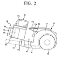
- FIG. 2 is a partial perspective view exemplifying an operation of separating the dust separating unit of FIG. 1 from a cleaner body;
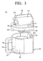
- FIG. 3 is an exploded perspective view of the dust separating unit of FIG. 2 ;
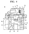
- FIG. 4 is a cross-sectional view of the dust separating unit of FIG. 2 ;
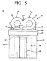
- FIG. 5 is a front elevation of the dust separating unit of FIG. 2
- FIG. 6 is a top plan-perspective view exemplifying a first cyclone unit of the dust separating unit of FIG. 3 ;
- FIG. 7 is a partial sectional view exemplifying a modified example of a second cyclone unit of the dust separating unit of FIG. 4 .
- FIGS. 1 and 2 schematically exemplify a vacuum cleaner 1 having a detachable dust separating unit 50 according to an exemplary embodiment of the present disclosure.
- the vacuum cleaner 1 includes a cleaner body 10, an extended tube 20, a suction nozzle assembly 30, and the detachable dust separating unit 50.
- the detachable dust separating unit 50 is detachably installed on a front part of the cleaner body 10, and a motor part (not illustrated) on which a suction motor (not illustrated) is mounted is installed in a rear part of the cleaner body 10.
- the cleaner body 10 includes an outer casing 11 forming an outward appearance. As illustrated in FIG. 2 , the outer casing 11 at a front part of an upper surface thereof has a first opening 11a formed in an approximately semicircle shape corresponding to a second cover 69 (see FIG. 3 ) of a second cyclone unit 65 to be described later, and at a front surface adjacent to the front part of the upper surface thereof has a second opening 11b formed in an approximately semicylinder shape.
- a seating part 80 which detachably mounts the dust separating unit 50 in the cleaner body 10, includes a recess 81 formed in the outer casing 11 to communicate in fluid with the first and the second openings 11a and 11b.
- the recess 81 has an accommodating space 83 in the form of a semicylinder formed in a shape corresponding to the dust separating unit 50.
- the accommodating space 83 may be formed, so that a bottom surface and a rear surface thereof are upwardly or diagonally inclined in a predetermined angle of, for example, 5 to 20 degrees, toward the second opening 11b with respect to a horizontal plane and a vertical plane, respectively.
- the accommodating space 83 may have a height and a front-and-rear width formed in such a size that when the dust separating unit 50 is mounted therein, a handle 62 of a first cyclone unit 55 and cyclones 71a and 71b disposed on the second cover 69 of the second cyclone unit 65, which will be described below, are projected to the outside through the second and the first openings 11b and 11a, respectively.
- a whole height and a whole front-and-rear width of the cleaner body 10 may be reduced by a width of the projected handle 62 of the first cyclone unit 55 and a height of the projected cyclones 71a and 71b.
- the cleaner body 10 may be reduced in entire size.
- a pair of side wheels 13 and bottom wheels are disposed on both sides and a bottom surface of the cleaner body 10 to move the cleaner body 10 along a surface to be cleaned in cleaning.
- An operating handle 21 is formed on an upper part of the extended tube 20, and a suction hose 15, which is connected with the cleaner body 10, is connected to a lower part of the operating handle 21.
- the suction nozzle assembly 30 is connected to a lower part of the extended tube 20 to draw in a dust or dirt along with an air from the surface to be cleaned.
- FIGS. 3 through 5 exemplify the dust separating unit 50 according to the exemplary embodiment of the present disclosure.
- the dust separating unit 50 as a multi cyclone dust-separating apparatus having a plurality of cyclones, includes a first cyclone unit 55 and a second cyclone unit 65.
- the first cyclone unit 55 which draws in the air drawn in through the suction nozzle assembly 30, the extended tube 20 and the suction hose 15 from the surface to be cleaned and first centrifugally separates the dust from the air, is configured, so that it draws in the air at a lower part thereof and discharges the air at an upper part thereof.
- the first cyclone unit 55 is provided with a first cyclone chamber 59 in the form of a cylinder having a first air inlet 56 formed on a side of the lower part thereof.
- the first air inlet 56 is coupled with an air drawing-in passage (not illustrated) formed in a lower side of the front part of the outer casing 11 to communicate in fluid with a connection socket 81a coupled to the suction hose 15.
- a center pipe 57 is disposed in a center of the first cyclone chamber 59 to guide a rotation of the air drawn in through the first air inlet 56.
- a spiral guide 58 is formed on an outer circumferential surface of the center pipe 57 to guide the air to rotate along the center pipe 57.
- a first dust collecting chamber 60 is disposed around the first cyclone chamber 59 to collect and store the dust centrifugally separated at the first cyclone chamber 59.
- the first dust collecting chamber 60 is formed in a tub shape with a semicircular cross section.
- the first dust collecting chamber 60 has a height higher than that of the first cyclone chamber 59, so that it can draw in the dust from the air whirling in the first cyclone chamber 59.
- the first dust collecting chamber 60 forms an outer appearance of the first cyclone unit 55, and is configured, so that a front surface thereof closes up the second opening 11b when the dust separating unit 50 is mounted on the seating part 80, as illustrated in FIG. 1 .
- the front surface of the first dust collecting chamber 60 may be formed of a transparent plastic material, so that a user can see, from the outside, whether it is filled with the dust.
- a second dust collecting chamber 61 is disposed at the rear of the first dust collecting chamber 60 to collect and store the dust centrifugally separated by the second cyclone unit 65.
- the second dust collecting chamber 61 may be formed in a tub shape having a rectangular cross section, which is separated from the first dust collecting chamber 60 by a partition 61a.
- the second dust collecting chamber 61 is located in the accommodating space 83 of the recess 81 positioned in the outer casing 11, so that it is not exposed to the outside when the dust separating unit 50 is mounted on the seating part 80.
- a rear surface of the second dust collecting chamber 61 may be formed of a transparent plastic material, so that the user can see, from the outside, whether it is filled with the dust.
- a whole front-and-rear width of the first and the second dust collecting chamber 60 and 61 constructed as described above is formed in a size corresponding to the front-and-rear width of the accommodating space 83 of the recess 81, that is, in such a size that when the dust separating unit 50 is mounted in the accommodating space 83 of the recess 81, the handle 62 of the first cyclone unit 55 is projected to the outside through the second opening 11b (see FIG. 1 ).
- the handle 62 is formed on a portion (that is, the front surface) opposite to a portion (that is, a rear surface) of the first dust collecting chamber 60 to which the second dust collecting chamber 61 is located. Because the whole front-and-rear width of the first and the second dust collecting chamber 60 and 61 is formed in the size corresponding to the front-and-rear width of the accommodating space 83 of the recess 81, the handle 62 is projected to the outside through the second opening 11b of the outer casing 11.
- the second cyclone unit 65 which second centrifugally separates a dust from the air discharged from the first cyclone unit 55, is detachably coupled with the first cyclone unit 55 above the first cyclone unit 55, as illustrated in FIG. 3 .
- the second cyclone unit 65 is provided with a first cover 66 to open and close up upper parts of the first and the second dust collecting chambers 60 and 61 of the first cyclone unit 55.
- a groove part 66a is formed on an undersurface of the first cover 66 to correspond to upper edges of the first and the second dust collecting chamber 60 and 61.
- the upper edges of the first and the second dust collecting chamber 60and 61 are inserted into or separated from the groove part 66a, and thus the first cover 66 can simultaneously close up or open the upper parts of the first and the second dust collecting chamber 60 and 61.
- An air drawing-in pipe 67 is formed on a center of the undersurface of the first cover 66 to draw in the air discharged from the first cyclone chamber 59 after the dust is separated at the first cyclone chamber 59.
- a grill member 68 is formed on a lower part of the air drawing-in pipe 67, and has a plurality of air holes to filter a fine dust from the discharged air.
- the grill member 68 is illustrated as being integrally formed with the air drawing-in pipe 67, but it can be separately formed from the air drawing-in pipe 67. The grill member 68 is projected into the first cyclone chamber 59, so that it is maintained in a spaced-apart relation to the center pipe 57.
- a guide partition 66b is formed in the first cover 66.
- the guide partition 66b forms a guide passage 75 to branch off and guide the air drawn in into the air drawing-in pipe 67 through the grill member 68 into second air inlets 70 of the horizontally arranged cyclones 71a and 71 b to be described later.
- a thickness of the first cover 66 having the guide passage 75 is formed in such a size that a whole height of which a height of the first cyclone unit 55 is added thereto conforms to the height of the accommodating space 83 of the recess 81, that is, in such a size that when the dust separating unit 50 is mounted in the accommodating space 83 of the recess 81, the cyclones 71a and 71 b disposed on the second cover 69 are projected to the outside through the first opening 11a.
- the second cover 69 is disposed on the first cover 66.
- the second cover 69 is detachably coupled with an upper edge of the first cover 66 and an upper edge of the guide partition 66b by a projected part 69a formed on a lower part of the second cover 69.
- the second cover 69 may be integrally formed with the first cover 66.
- the second cover 69 is formed in a size and a shape (that is, a semicircular shape) corresponding to the first opening 11a of the outer casing 11, so that when the dust separating unit 50 is mounted on or separated from the seating part 80, it can close up or open the first opening 11a.
- a plurality of, for example, two cyclones 71a and 7 1 b are installed on the second cover 69 to second separate a dust from the air by using a centrifugal force.
- the two cyclones 71 a and 71 b are symmetrically arranged in parallel and adjacent to each other. Because the two cyclones 71a and 71 b are formed in such a size that a height of which the height of the first cyclone unit 55 and the thickness of the first cover 66 are combined conforms to the height of the accommodating space 83 of the recess 81 as described above, they are projected to the outside through the first opening 11a of the outer casing 11 when the dust separating unit 50 is mounted on the seating part 80.
- each of the cyclones 71a and 71b is arranged, so that a line of center axis thereof is positioned in a right angle to a line of center axis of the whirling current in the first cyclone chamber 59.
- Each of the cyclones 71a and 71b includes a second air inlet 70, a second cyclone chamber 72, a guide pipe 73, a discharging pipe 77, and a dust charging part 74. Since each of the cyclones 71a and 7 1 b has the same elements and functions, only one cyclone 71a will be explained.
- the second air inlet 70 at a lower end thereof is coupled with the guide passage 75 and at an upper end thereof is coupled in a tangential shape to a front side (a left side in FIG. 4 ) of the second cyclone chamber 72.
- the second cyclone chamber 72 which provides a space to allow the air drawn in through the second air inlet 70 to whirl, may be formed in a cylinder shape.
- the second cyclone chamber 72 may be formed in a convex cylinder shape or a truncated cone shape.
- the second cyclone chamber 72 may be formed of a transparent plastic material.
- the guide pipe 73 and the discharging pipe 77 are arranged in the front and the rear of the second cyclone chamber 72 to face to each other while having the same center axis.
- the discharging pipe 77 has a grill 77a disposed on a front end thereof to filter a fine dust from the air discharged from the second cyclone chamber 72.
- the grill 77a may be omitted or removed, as in the second cyclone unit 65' of the modified example illustrated in FIG. 7 .
- the discharging pipe 77 at a rear end (a right side end in FIG. 4 ) thereof is penetrated through and slightly projected from the second cyclone chamber 72. Accordingly, when the dust separating unit 50 is mounted on the seating part 80, the rear end of the discharging pipe 77 is connected to an inlet of a discharging passage (not illustrated) formed in the seating part 80 to communicate in fluid with the suction motor.
- a discharging passage not illustrated
- the dust charging part 74 is arranged below a rear end of the second cyclone chamber 72 to send the fine dust centrifugally separated from the air to the second dust collecting chamber 61 of the first cyclone unit 55 through a dust discharging passage 76 of the first cover 66.
- the dust separating unit 50 is illustrated and explained as being the multi cyclone dust separating apparatus including the second cyclone unit 65 with the two cyclones 71a and 71b, the present disclosure is not limited thereto.
- the dust separating unit 50 may be formed in a configuration including a second cyclone unit with a plurality of cyclones arranged in a radial direction above a first cyclone unit.
- the vacuum cleaner 1 is configured, so that the entire of the dust separating unit 50 having the plurality of cyclones, that is, the first and the second cyclone units 55 and 65 is detachably mounted to the cleaner body 10. Accordingly, in maintenance and repair, the user can separate the entire of the dust separating unit 50 from the cleaner body 10 and then move the dust separating unit 50 to an outer wide area to maintain and repair the dust separating unit 50 thereat.
- the vacuum cleaner 1 according to the exemplary embodiment of the present disclosure is configured, so that the first and the second cyclone units 55 and 65 of the dust separating unit 50 are detachably coupled to or with each other. Accordingly, the first and/or the second cyclone units 55 and/or 65 can be easily maintained and repaired.
- the vacuum cleaner 1 is configured, so that some components of the dust separating unit 50, that is, the handle 62 of the first cyclone unit 55 and the cyclones 71a and 71b of the second cyclone unit 65 are arranged to project to the outside. Accordingly, there is no need for forming the seating part 80 of mounting the dust separating unit 50 to have a height and a width identical to or larger than the entire height and the entire width of the dust separating unit 50.
- the vacuum cleaner 1 according to the exemplary embodiment of the present disclosure can detachably mount the dust separating unit 50 with the plurality of cyclones for superior dust-separating performance while not greatly increasing the vacuum cleaner 10 in size.
- the suction motor is operated. As a result, an air is drawn in into the first air inlet 56 through the suction nozzle assembly 30, the extended tube 20 and the suction hose 15 along with a dust or dirt in the vicinity of a surface to be cleaned.
- the air drawn in into the first air inlet 56 is changed into a whirling current while being guided by the spiral guide 58 of the center pipe 57, and is drawn into the first cyclone chamber 59.
- a centrifugal action of the whirling current ascending by a suction force of the suction motor a relatively large dust is separated from the air drawn in into the first cyclone chamber 59.
- the separated dust is moved toward and collected into the first dust collecting chamber 60.
- the air from which the dust is first separated passes through the grill member 68 to filter off a fine dust therefrom again, and flows into the second air inlets 70 of the two cyclones 71a and 71 b via the air drawing-in pipe 67 and the guide passage 75.
- the air flowed into the second air inlets 70 is changed into a whirling current while being dashed against an inner circumferential surface of the second cyclone chamber 72 and guided by the guide pipe 73 and the discharging pipe 77.
- a dust is second separated from the air by the centrifugal force of the whirling current.
- the dust separated from the air in the second cyclone chamber 72 is collected into the second dust collecting chamber 61 through the dust discharging part 74 and the dust discharging passage 76.
- the air from which the dust is second separated passes through the grill 77a to filter off a fine dust therefrom again, and discharges into the discharging passage formed in the seating part 80 through the discharging pipe 77.
- the discharged air is united into one in the discharging passage and discharged to the outside through the suction motor.
- the user grasps the handle 62 and draws out the entire of the dust separating unit 50 from the seating part 80. And then, as illustrated in FIG. 3 , the user pulls the second cyclone unit 65 up while grasping the handle 62. As a result, the upper edges of the first and second dust collecting chambers 60 and 61 are separated from the groove part 66a of the first cover 66 to open the upper parts of the first and second dust collecting chambers 60 and 61. In this state, the dust collected in the first and second dust collecting chambers 60 and 61 is removed from the first and second dust collecting chambers 60 and 61 and dumped on a dustbin, and the dust removing operation is completed.
- the user places the second cyclone unit 65 on the first cyclone unit 55 and then inserts the upper edges of the first and second dust collecting chambers 60 and 61 into the groove part 66a of the first cover 66 to couple the second cyclone unit 65 with the first cyclone unit 55. And then, the user grasps the handle 62 and pushes the dust separating unit 50 into the recess 81 of the seating part 80 to mount the dust separating unit 50 in the seating part 80. At this time, the second cover 69 closes up the first opening 11a of the outer casing 11 and the front surface of the first dust collecting chamber 60 closes up the second opening 11b of the outer casing 11.
- the first air inlet 56 is connected with the air drawing-in passage communicating in fluid with the connection socket 81a coupled to the suction hose 15, and the rear ends of the discharging pipes 77 of the two cyclones 71a and 71b are coupled with inlets of the discharging passage. Also, the two cyclones 71a and 71b and the handle 62 are projected to the outside of the outer casing 11 through the first and the second openings 11a and 11b of the outer casing 11, respectively. As a result, the mounting operation is completed.
- the vacuum cleaner is configured, so that the entire of the large volume of dust separating unit, such as the multi cyclone dust separating apparatus, having the plurality of cyclones, that is, the first and the second cyclone units, is detachably mounted to the cleaner body. Accordingly, in maintenance and repair, the user can separate the entire of the dust separating unit from the cleaner body and then move the dust separating unit to the outer wide area to maintain and repair the dust separating unit thereat.
- the entire of the large volume of dust separating unit such as the multi cyclone dust separating apparatus, having the plurality of cyclones, that is, the first and the second cyclone units
- the vacuum cleaner according to the exemplary embodiment of the present disclosure is configured, so that the first and the second cyclone units of the dust separating unit are detachably coupled to or with each other. Accordingly, the first and/or the second cyclone units can be easily maintained and repaired.
- the vacuum cleaner according to the exemplary embodiment of the present disclosure is configured, so that some components of the large volume of dust separating unit, such as the multi cyclone dust separating apparatus, that is, at least the handle of the first cyclone unit and the cyclones of the second cyclone unit, are arranged to project to the outside. Accordingly, there is no need for forming the seating part of mounting the dust separating unit to have the height and the width identical to or larger than the entire height and the entire width of the dust separating unit.
- the vacuum cleaner according to the exemplary embodiment of the present disclosure can detachably mount the large volume of dust separating unit, but design the cleaner body to have about the same size as the dust separating unit having the single cyclone in the conventional vacuum cleaner.
- the vacuum cleaner according to the exemplary embodiment of the present disclosure can detachably mount the large volume of separating unit, such as the multi cyclone dust separating apparatus, for superior dust-separating performance while not greatly increasing the vacuum cleaner in size.
Landscapes
- Engineering & Computer Science (AREA)
- Mechanical Engineering (AREA)
- Filters For Electric Vacuum Cleaners (AREA)
- Nozzles For Electric Vacuum Cleaners (AREA)
Claims (14)
- Staubsauger, der aufweist:einen Staubsaugerkörper (10) mit einer ersten Öffnung (11a), um einen Abschnitt einer ersten Oberfläche desselben zu öffnen, und einer zweiten Öffnung (11b), um einen Abschnitt einer zweiten Oberfläche desselben zu öffnen;eine Staubtrenneinheit (50), um Staub von Luft zu trennen; undeinen Sitzteil (80), der im Staubsaugerkörper (10) ausgebildet ist, um die Staubtrenneinheit (50) am Staubsaugerkörper (10) lösbar zu montieren, wobei der Sitzteil (80) eine Aussparung (81) mit einem Aufnahmeraum (83) aufweist, der mit der ersten und der zweiten Öffnung (11a, 11b) des Staubsaugerkörpers (10) fluidtechnisch in Verbindung steht und in einer Gestalt ausgebildet ist, die der Staubtrenneinheit (50) entspricht;wobei die Staubtrenneinheit (50) dazu ausgelegt ist, einen Abschnitt eines äußeren Aussehens des Staubsaugerkörpers (10) zu bilden, während sie die erste und die zweite Öffnung (11a, 11b) des Staubsaugerkörpers (10) verschließt, wenn die Staubtrenneinheit (50) am Sitzteil (80) montiert ist;dadurch gekennzeichnet, dassder Aufnahmeraum (83) geneigt ist, so dass er in Richtung zumindest der zweiten Öffnung (11b) in Bezug auf eine horizontale Ebene ansteigt.
- Staubsauger nach Anspruch 1, wobei die Staubtrenneinheit (50) so ausgelegt ist, dass, wenn die Staubtrenneinheit (50) am Sitzteil (80) montiert ist, ein Abschnitt derselben durch die erste und die zweite Öffnung (11a, 11b) des Staubsaugerkörpers (10) nach außen vorsteht.
- Staubsauger nach Anspruch 1 oder 2,
wobei die Staubtrenneinheit (50) eine erste Zykloneinheit (55), um Luft einzusaugen und erstmalig Staub von der Luft zentrifugal zu trennen, und eine zweite Zykloneinheit (65), um Staub von der aus der ersten Zykloneinheit (55) ausgelassenen Luft zweitmalig zentrifugal zu trennen, aufweist, und
wobei die erste Zykloneinheit (55) einen Abschnitt aufweist, der durch die zweite Öffnung (11b) des Staubsaugerkörpers (10) nach außen vorsteht, und die zweite Zykloneinheit (65) einen Abschnitt aufweist, der durch die erste Öffnung (11a) nach außen vorsteht. - Staubsauger nach Anspruch 3, wobei die erste und die zweite Zykloneinheit (55, 65) lösbar miteinander gekoppelt sind.
- Staubsauger nach Anspruch 3 oder 4, wobei die erste Zykloneinheit (55) die Luft an einem unteren Teil derselben einsaugt und die Luft an einem oberen Teil derselben auslässt.
- Staubsauger nach einem der Ansprüche 3 bis 5, wobei die erste Zykloneinheit (55) aufweist:eine erste Zyklonkammer (59) mit einem Lufteinlass (56) am unteren Teil derselben;ein zentrales Rohr (57), das in einem Zentrum der ersten Zyklonkammer (59) angeordnet ist, um eine Drehung der durch den Lufteinlass (56) eingesaugten Luft zu führen;eine erste Staubsammelkammer (60), die um die erste Zyklonkammer (59) angeordnet ist, um den von der ersten Zykloneinheit (55) zentrifugal abgetrennten Staub zu lagern; undeine zweite Staubsammelkammer (61), die auf einer Seite der ersten Staubsammelkammer (60) angeordnet ist, um den von der zweiten Zykloneinheit (65) zentrifugal abgetrennten Staub zu lagern.
- Staubsauger nach Anspruch 6, wobei die erste Staubsammelkammer (60) in einer Gestalt mit einem halbkreisförmigen Querschnitt ausgebildet ist und die zweite Staubsammelkammer (61) in einer Gestalt mit einem rechteckigen Querschnitt ausgebildet ist.
- Staubsauger nach Anspruch 6 oder 7, wobei die erste Staubsammelkammer (60) so ausgelegt ist, dass zumindest ein Abschnitt derselben die zweite Öffnung (11b) des Staubsaugerkörpers (10) verschließt, wenn die Staubtrenneinheit (50) am Sitzteil (80) montiert ist.
- Staubsauger nach einem der Ansprüche 6 bis 8, wobei die erste Zykloneinheit (55) ferner einen Griff (62) aufweist, der an der ersten Staubsammelkammer (60) ausgebildet ist, wobei der Griff vorzugsweise so ausgelegt ist, dass zumindest ein Abschnitt desselben durch die zweite Öffnung (11b) des Staubsaugerkörpers (10) nach außen vorsteht.
- Staubsauger nach einem der Ansprüche 3 bis 9, wobei die zweite Zykloneinheit (65) mindestens zwei Zyklone (71a, 71b) aufweist, die horizontal parallel zueinander über der ersten Zykloneinheit (55) angeordnet sind.
- Staubsauger nach Anspruch 10, wobei jeder der mindestens zwei Zyklone (71a, 71b) so ausgelegt ist, dass zumindest ein Abschnitt derselben durch die erste Öffnung (11a) des Staubsaugerkörpers (10) nach außen vorsteht.
- Staubsauger nach einem der Ansprüche 6 bis 11, wobei die zweite Zykloneinheit (65) ferner eine erste Abdeckung (66) aufweist, um einen oberen Teil der ersten Zykloneinheit (55) zu öffnen und zu verschließen, wobei die erste Abdeckung vorzugsweise dazu ausgelegt ist, die erste Staubsammelkammer (60) und die zweite Staubsammelkammer (61) der ersten Zykloneinheit (55) gleichzeitig zu öffnen und zu verschließen.
- Staubsauger nach Anspruch 12, wobei die zweite Zykloneinheit (65) ferner eine zweite Abdeckung (69) aufweist, um die erste Öffnung (11a) des Staubsaugerkörpers (10) zu öffnen und zu verschließen, wobei die zweite Abdeckung vorzugsweise dazu ausgelegt ist, die erste Öffnung (11a) zu verschließen, wenn die Staubtrenneinheit (50) am Sitzteil (80) montiert ist.
- Staubsauger nach einem der Ansprüche 6 bis 13, wobei die zweite Zykloneinheit (65) ferner ein Gitterelement (68) aufweist, um Staub von der aus der ersten Zykloneinheit (55) ausgelassenen Luft zu filtern, wobei das Gitterelement (68) vorzugsweise so ausgelegt ist, dass zumindest ein Abschnitt desselben in die erste Zyklonkammer (59) der ersten Zykloneinheit (55) vorsteht und in einer beabstandeten Beziehung zu einem zentralen Rohr (57) der ersten Zykloneinheit (55) gehalten wird.
Applications Claiming Priority (1)
| Application Number | Priority Date | Filing Date | Title |
|---|---|---|---|
| KR1020080135968A KR101542185B1 (ko) | 2008-12-29 | 2008-12-29 | 분리할 수 있는 집진장치를 구비한 진공청소기 |
Publications (3)
| Publication Number | Publication Date |
|---|---|
| EP2201880A2 EP2201880A2 (de) | 2010-06-30 |
| EP2201880A3 EP2201880A3 (de) | 2012-09-26 |
| EP2201880B1 true EP2201880B1 (de) | 2013-09-25 |
Family
ID=41612366
Family Applications (1)
| Application Number | Title | Priority Date | Filing Date |
|---|---|---|---|
| EP09014244.9A Active EP2201880B1 (de) | 2008-12-29 | 2009-11-13 | Staubsauger mit abnehmbarer Staubtrenneinheit |
Country Status (5)
| Country | Link |
|---|---|
| US (1) | US20100162517A1 (de) |
| EP (1) | EP2201880B1 (de) |
| KR (1) | KR101542185B1 (de) |
| AU (1) | AU2009238258B2 (de) |
| RU (1) | RU2520051C2 (de) |
Families Citing this family (25)
| Publication number | Priority date | Publication date | Assignee | Title |
|---|---|---|---|---|
| GB2436308A (en) * | 2006-03-23 | 2007-09-26 | Adrian Christopher Arnold | Particle separator |
| GB2455535A (en) * | 2007-12-12 | 2009-06-17 | Prime Sourcing Ltd | Cyclone chamber with vortex shield |
| US8152877B2 (en) * | 2010-03-12 | 2012-04-10 | Euro-Pro Operating Llc | Shroud for a cleaning service apparatus |
| USD683506S1 (en) * | 2011-01-28 | 2013-05-28 | Samsung Electronics Co., Ltd. | Dust collecting case for vacuum cleaner |
| US8728186B2 (en) | 2011-09-02 | 2014-05-20 | Samsung Electronics Co., Ltd. | Vacuum cleaner and dust separating apparatus thereof |
| GB2503251C (en) * | 2012-06-20 | 2015-07-15 | Dyson Technology Ltd | A self righting cleaning appliance |
| GB2503254B (en) * | 2012-06-20 | 2014-12-17 | Dyson Technology Ltd | A cleaning appliance |
| GB2503255B (en) * | 2012-06-20 | 2014-10-15 | Dyson Technology Ltd | A cleaning appliance |
| GB2503252B (en) | 2012-06-20 | 2014-12-17 | Dyson Technology Ltd | A self righting cleaning appliance |
| GB2503253B (en) * | 2012-06-20 | 2014-10-15 | Dyson Technology Ltd | A cleaning appliance |
| GB2503670B (en) | 2012-07-03 | 2014-12-10 | Dyson Technology Ltd | Method of preheating a brushless motor |
| GB2503671B (en) | 2012-07-03 | 2014-12-17 | Dyson Technology Ltd | Control of a brushless motor |
| JP5333633B1 (ja) * | 2012-08-02 | 2013-11-06 | 三菱電機株式会社 | 電気掃除機 |
| JP5472417B1 (ja) * | 2012-09-28 | 2014-04-16 | 三菱電機株式会社 | 遠心分離装置 |
| KR102049860B1 (ko) * | 2013-03-27 | 2020-01-08 | 엘지전자 주식회사 | 청소기 |
| DE102013217211A1 (de) * | 2013-08-28 | 2015-03-05 | BSH Bosch und Siemens Hausgeräte GmbH | Wirbelrohrabscheider mit Auswurföffnung für Grobschmutz |
| KR102180680B1 (ko) * | 2014-02-10 | 2020-11-20 | 삼성전자주식회사 | 사이클론 집진장치 및 이를 갖는 청소기 |
| WO2015123538A1 (en) | 2014-02-14 | 2015-08-20 | Techtronic Industries Co. Ltd. | Vacuum cleaner with a separator received within the dirt collection chamber |
| KR101622724B1 (ko) * | 2014-09-29 | 2016-05-19 | 엘지전자 주식회사 | 진공청소기용 집진장치 |
| KR101641256B1 (ko) | 2014-10-07 | 2016-07-20 | 엘지전자 주식회사 | 진공 청소기용 집진장치 |
| US10117551B2 (en) | 2014-10-22 | 2018-11-06 | Techtronic Industries Co. Ltd. | Handheld vacuum cleaner |
| WO2016065148A2 (en) | 2014-10-22 | 2016-04-28 | Techtronic Industries Co. Ltd. | Vacuum cleaner having cyclonic separator |
| WO2016065146A1 (en) | 2014-10-22 | 2016-04-28 | Techtronic Industries Co. Ltd. | Vacuum cleaner having cyclonic separator |
| JP6041023B1 (ja) * | 2015-08-05 | 2016-12-07 | 三菱電機株式会社 | 電気掃除機 |
| US11432693B2 (en) | 2020-03-12 | 2022-09-06 | Techtronic Floor Care Technology Limited | Vacuum cleaner |
Family Cites Families (13)
| Publication number | Priority date | Publication date | Assignee | Title |
|---|---|---|---|---|
| SE512295C2 (sv) * | 1999-04-08 | 2000-02-28 | Electrolux Ab | Tömningssystem för en cyklondammsugare |
| GB2404887A (en) * | 2003-08-13 | 2005-02-16 | Dyson Ltd | Grooved outlet for cyclonic separating apparatus |
| KR100633605B1 (ko) * | 2004-12-27 | 2006-10-11 | 엘지전자 주식회사 | 진공 청소기의 집진유닛 |
| KR100697429B1 (ko) * | 2004-12-27 | 2007-03-20 | 엘지전자 주식회사 | 진공 청소기 |
| KR100560967B1 (ko) * | 2005-01-14 | 2006-03-15 | 삼성광주전자 주식회사 | 사이클론 집진장치 |
| KR100611026B1 (ko) * | 2005-03-29 | 2006-08-10 | 삼성광주전자 주식회사 | 진공청소기용 멀티 사이클론 집진장치 |
| KR100651871B1 (ko) | 2005-05-19 | 2006-12-01 | 엘지전자 주식회사 | 진공청소기 |
| US20070144116A1 (en) * | 2005-12-23 | 2007-06-28 | Samsung Electronics Co., Ltd. | Cyclonic cleaner |
| KR101250077B1 (ko) * | 2006-04-04 | 2013-04-02 | 엘지전자 주식회사 | 진공 청소기의 집진 유닛 |
| KR100776402B1 (ko) | 2007-02-05 | 2007-11-16 | 삼성광주전자 주식회사 | 필터조립체를 구비한 멀티 사이클론 분리장치 |
| KR100776403B1 (ko) * | 2007-02-14 | 2007-11-16 | 삼성광주전자 주식회사 | 진공청소기용 사이클론 집진장치 |
| KR101309780B1 (ko) * | 2007-04-17 | 2013-09-23 | 삼성전자주식회사 | 진공청소기의 사이클론 집진장치 |
| KR101340423B1 (ko) * | 2007-08-28 | 2013-12-13 | 삼성전자주식회사 | 스틱형 진공청소기 |
-
2008
- 2008-12-29 KR KR1020080135968A patent/KR101542185B1/ko active Active
-
2009
- 2009-11-05 US US12/590,260 patent/US20100162517A1/en not_active Abandoned
- 2009-11-13 AU AU2009238258A patent/AU2009238258B2/en not_active Ceased
- 2009-11-13 EP EP09014244.9A patent/EP2201880B1/de active Active
- 2009-12-28 RU RU2009149157/12A patent/RU2520051C2/ru active
Also Published As
| Publication number | Publication date |
|---|---|
| AU2009238258A1 (en) | 2010-07-15 |
| AU2009238258B2 (en) | 2015-02-12 |
| EP2201880A3 (de) | 2012-09-26 |
| US20100162517A1 (en) | 2010-07-01 |
| KR101542185B1 (ko) | 2015-08-07 |
| EP2201880A2 (de) | 2010-06-30 |
| RU2520051C2 (ru) | 2014-06-20 |
| KR20100077893A (ko) | 2010-07-08 |
| RU2009149157A (ru) | 2011-07-10 |
Similar Documents
| Publication | Publication Date | Title |
|---|---|---|
| EP2201880B1 (de) | Staubsauger mit abnehmbarer Staubtrenneinheit | |
| KR100536506B1 (ko) | 사이클론 분리장치 및 이를 구비한 진공청소기 | |
| KR100554237B1 (ko) | 사이클론 분리장치 및 이를 구비한 진공청소기 | |
| US8568500B2 (en) | Multi-cyclone dust separator and a vacuum cleaner using the same | |
| KR100536503B1 (ko) | 사이클론 분리장치 및 이를 구비한 진공청소기 | |
| EP2218386B1 (de) | Staubtrennungsvorrichtung eines Staubsaugers | |
| KR100648960B1 (ko) | 멀티 사이클론 분리장치 | |
| US6977003B2 (en) | Cyclone dust-collecting apparatus of vacuum cleaner | |
| KR100648959B1 (ko) | 멀티 사이클론 분리장치 | |
| EP1989984B1 (de) | Zyklonstaubtrennvorrichtung eines Staubsaugers | |
| EP1857032B1 (de) | Staubsauger mit primärer und sekundären Zykloneinheiten | |
| EP1477099A2 (de) | Staubsammeleinheit eines Staubsaugers | |
| JP2005081137A (ja) | サイクロン分離装置およびこれを備えた真空掃除機 | |
| GB2456192A (en) | Sloped upper wall of cyclone inflow channel | |
| CN1505486A (zh) | 吸尘器 | |
| KR100934668B1 (ko) | 진공 청소기의 집진장치 | |
| EP1676638A2 (de) | Staubsammelvorrichtung und Staubsauger mit solch einer Vorrichtung | |
| AU2008238967B2 (en) | Dust separating apparatus of vacuum cleaner | |
| KR100546627B1 (ko) | 진공 청소기의 집진장치 | |
| EP2277426B1 (de) | Staubsauger | |
| KR100556444B1 (ko) | 진공 청소기의 집진장치 | |
| KR100617131B1 (ko) | 청소기의 집진장치 | |
| KR100546628B1 (ko) | 진공 청소기의 집진장치 | |
| KR100556443B1 (ko) | 진공 청소기의 집진장치 | |
| KR100546624B1 (ko) | 청소기의 집진장치 |
Legal Events
| Date | Code | Title | Description |
|---|---|---|---|
| PUAI | Public reference made under article 153(3) epc to a published international application that has entered the european phase |
Free format text: ORIGINAL CODE: 0009012 |
|
| AK | Designated contracting states |
Kind code of ref document: A2 Designated state(s): AT BE BG CH CY CZ DE DK EE ES FI FR GB GR HR HU IE IS IT LI LT LU LV MC MK MT NL NO PL PT RO SE SI SK SM TR |
|
| AX | Request for extension of the european patent |
Extension state: AL BA RS |
|
| RAP1 | Party data changed (applicant data changed or rights of an application transferred) |
Owner name: SAMSUNG ELECTRONICS CO., LTD. |
|
| PUAL | Search report despatched |
Free format text: ORIGINAL CODE: 0009013 |
|
| AK | Designated contracting states |
Kind code of ref document: A3 Designated state(s): AT BE BG CH CY CZ DE DK EE ES FI FR GB GR HR HU IE IS IT LI LT LU LV MC MK MT NL NO PL PT RO SE SI SK SM TR |
|
| AX | Request for extension of the european patent |
Extension state: AL BA RS |
|
| RAP1 | Party data changed (applicant data changed or rights of an application transferred) |
Owner name: SAMSUNG ELECTRONICS CO., LTD. |
|
| RIC1 | Information provided on ipc code assigned before grant |
Ipc: A47L 9/16 20060101AFI20120820BHEP |
|
| 17P | Request for examination filed |
Effective date: 20130326 |
|
| GRAP | Despatch of communication of intention to grant a patent |
Free format text: ORIGINAL CODE: EPIDOSNIGR1 |
|
| INTG | Intention to grant announced |
Effective date: 20130502 |
|
| GRAS | Grant fee paid |
Free format text: ORIGINAL CODE: EPIDOSNIGR3 |
|
| GRAA | (expected) grant |
Free format text: ORIGINAL CODE: 0009210 |
|
| AK | Designated contracting states |
Kind code of ref document: B1 Designated state(s): AT BE BG CH CY CZ DE DK EE ES FI FR GB GR HR HU IE IS IT LI LT LU LV MC MK MT NL NO PL PT RO SE SI SK SM TR |
|
| REG | Reference to a national code |
Ref country code: GB Ref legal event code: FG4D |
|
| REG | Reference to a national code |
Ref country code: CH Ref legal event code: EP |
|
| REG | Reference to a national code |
Ref country code: AT Ref legal event code: REF Ref document number: 633401 Country of ref document: AT Kind code of ref document: T Effective date: 20131015 |
|
| REG | Reference to a national code |
Ref country code: IE Ref legal event code: FG4D |
|
| REG | Reference to a national code |
Ref country code: DE Ref legal event code: R096 Ref document number: 602009019005 Country of ref document: DE Effective date: 20131121 |
|
| PG25 | Lapsed in a contracting state [announced via postgrant information from national office to epo] |
Ref country code: HR Free format text: LAPSE BECAUSE OF FAILURE TO SUBMIT A TRANSLATION OF THE DESCRIPTION OR TO PAY THE FEE WITHIN THE PRESCRIBED TIME-LIMIT Effective date: 20130925 Ref country code: SE Free format text: LAPSE BECAUSE OF FAILURE TO SUBMIT A TRANSLATION OF THE DESCRIPTION OR TO PAY THE FEE WITHIN THE PRESCRIBED TIME-LIMIT Effective date: 20130925 Ref country code: NO Free format text: LAPSE BECAUSE OF FAILURE TO SUBMIT A TRANSLATION OF THE DESCRIPTION OR TO PAY THE FEE WITHIN THE PRESCRIBED TIME-LIMIT Effective date: 20131225 Ref country code: LT Free format text: LAPSE BECAUSE OF FAILURE TO SUBMIT A TRANSLATION OF THE DESCRIPTION OR TO PAY THE FEE WITHIN THE PRESCRIBED TIME-LIMIT Effective date: 20130925 |
|
| REG | Reference to a national code |
Ref country code: AT Ref legal event code: MK05 Ref document number: 633401 Country of ref document: AT Kind code of ref document: T Effective date: 20130925 |
|
| REG | Reference to a national code |
Ref country code: NL Ref legal event code: VDEP Effective date: 20130925 |
|
| REG | Reference to a national code |
Ref country code: LT Ref legal event code: MG4D |
|
| PG25 | Lapsed in a contracting state [announced via postgrant information from national office to epo] |
Ref country code: LV Free format text: LAPSE BECAUSE OF FAILURE TO SUBMIT A TRANSLATION OF THE DESCRIPTION OR TO PAY THE FEE WITHIN THE PRESCRIBED TIME-LIMIT Effective date: 20130925 Ref country code: GR Free format text: LAPSE BECAUSE OF FAILURE TO SUBMIT A TRANSLATION OF THE DESCRIPTION OR TO PAY THE FEE WITHIN THE PRESCRIBED TIME-LIMIT Effective date: 20131226 Ref country code: SI Free format text: LAPSE BECAUSE OF FAILURE TO SUBMIT A TRANSLATION OF THE DESCRIPTION OR TO PAY THE FEE WITHIN THE PRESCRIBED TIME-LIMIT Effective date: 20130925 Ref country code: FI Free format text: LAPSE BECAUSE OF FAILURE TO SUBMIT A TRANSLATION OF THE DESCRIPTION OR TO PAY THE FEE WITHIN THE PRESCRIBED TIME-LIMIT Effective date: 20130925 |
|
| PG25 | Lapsed in a contracting state [announced via postgrant information from national office to epo] |
Ref country code: BE Free format text: LAPSE BECAUSE OF FAILURE TO SUBMIT A TRANSLATION OF THE DESCRIPTION OR TO PAY THE FEE WITHIN THE PRESCRIBED TIME-LIMIT Effective date: 20130925 |
|
| PG25 | Lapsed in a contracting state [announced via postgrant information from national office to epo] |
Ref country code: SK Free format text: LAPSE BECAUSE OF FAILURE TO SUBMIT A TRANSLATION OF THE DESCRIPTION OR TO PAY THE FEE WITHIN THE PRESCRIBED TIME-LIMIT Effective date: 20130925 Ref country code: IS Free format text: LAPSE BECAUSE OF FAILURE TO SUBMIT A TRANSLATION OF THE DESCRIPTION OR TO PAY THE FEE WITHIN THE PRESCRIBED TIME-LIMIT Effective date: 20140125 Ref country code: NL Free format text: LAPSE BECAUSE OF FAILURE TO SUBMIT A TRANSLATION OF THE DESCRIPTION OR TO PAY THE FEE WITHIN THE PRESCRIBED TIME-LIMIT Effective date: 20130925 Ref country code: RO Free format text: LAPSE BECAUSE OF FAILURE TO SUBMIT A TRANSLATION OF THE DESCRIPTION OR TO PAY THE FEE WITHIN THE PRESCRIBED TIME-LIMIT Effective date: 20130925 Ref country code: CZ Free format text: LAPSE BECAUSE OF FAILURE TO SUBMIT A TRANSLATION OF THE DESCRIPTION OR TO PAY THE FEE WITHIN THE PRESCRIBED TIME-LIMIT Effective date: 20130925 Ref country code: EE Free format text: LAPSE BECAUSE OF FAILURE TO SUBMIT A TRANSLATION OF THE DESCRIPTION OR TO PAY THE FEE WITHIN THE PRESCRIBED TIME-LIMIT Effective date: 20130925 |
|
| PG25 | Lapsed in a contracting state [announced via postgrant information from national office to epo] |
Ref country code: PL Free format text: LAPSE BECAUSE OF FAILURE TO SUBMIT A TRANSLATION OF THE DESCRIPTION OR TO PAY THE FEE WITHIN THE PRESCRIBED TIME-LIMIT Effective date: 20130925 Ref country code: CY Free format text: LAPSE BECAUSE OF FAILURE TO SUBMIT A TRANSLATION OF THE DESCRIPTION OR TO PAY THE FEE WITHIN THE PRESCRIBED TIME-LIMIT Effective date: 20130925 Ref country code: AT Free format text: LAPSE BECAUSE OF FAILURE TO SUBMIT A TRANSLATION OF THE DESCRIPTION OR TO PAY THE FEE WITHIN THE PRESCRIBED TIME-LIMIT Effective date: 20130925 Ref country code: ES Free format text: LAPSE BECAUSE OF FAILURE TO SUBMIT A TRANSLATION OF THE DESCRIPTION OR TO PAY THE FEE WITHIN THE PRESCRIBED TIME-LIMIT Effective date: 20130925 |
|
| REG | Reference to a national code |
Ref country code: DE Ref legal event code: R097 Ref document number: 602009019005 Country of ref document: DE |
|
| PG25 | Lapsed in a contracting state [announced via postgrant information from national office to epo] |
Ref country code: PT Free format text: LAPSE BECAUSE OF FAILURE TO SUBMIT A TRANSLATION OF THE DESCRIPTION OR TO PAY THE FEE WITHIN THE PRESCRIBED TIME-LIMIT Effective date: 20140127 |
|
| REG | Reference to a national code |
Ref country code: CH Ref legal event code: PL |
|
| PG25 | Lapsed in a contracting state [announced via postgrant information from national office to epo] |
Ref country code: LI Free format text: LAPSE BECAUSE OF NON-PAYMENT OF DUE FEES Effective date: 20131130 Ref country code: CH Free format text: LAPSE BECAUSE OF NON-PAYMENT OF DUE FEES Effective date: 20131130 Ref country code: MC Free format text: LAPSE BECAUSE OF FAILURE TO SUBMIT A TRANSLATION OF THE DESCRIPTION OR TO PAY THE FEE WITHIN THE PRESCRIBED TIME-LIMIT Effective date: 20130925 |
|
| PLBE | No opposition filed within time limit |
Free format text: ORIGINAL CODE: 0009261 |
|
| STAA | Information on the status of an ep patent application or granted ep patent |
Free format text: STATUS: NO OPPOSITION FILED WITHIN TIME LIMIT |
|
| REG | Reference to a national code |
Ref country code: FR Ref legal event code: ST Effective date: 20140731 |
|
| REG | Reference to a national code |
Ref country code: IE Ref legal event code: MM4A |
|
| PG25 | Lapsed in a contracting state [announced via postgrant information from national office to epo] |
Ref country code: IT Free format text: LAPSE BECAUSE OF FAILURE TO SUBMIT A TRANSLATION OF THE DESCRIPTION OR TO PAY THE FEE WITHIN THE PRESCRIBED TIME-LIMIT Effective date: 20130925 |
|
| 26N | No opposition filed |
Effective date: 20140626 |
|
| PG25 | Lapsed in a contracting state [announced via postgrant information from national office to epo] |
Ref country code: DK Free format text: LAPSE BECAUSE OF FAILURE TO SUBMIT A TRANSLATION OF THE DESCRIPTION OR TO PAY THE FEE WITHIN THE PRESCRIBED TIME-LIMIT Effective date: 20130925 |
|
| REG | Reference to a national code |
Ref country code: DE Ref legal event code: R097 Ref document number: 602009019005 Country of ref document: DE Effective date: 20140626 |
|
| PG25 | Lapsed in a contracting state [announced via postgrant information from national office to epo] |
Ref country code: IE Free format text: LAPSE BECAUSE OF NON-PAYMENT OF DUE FEES Effective date: 20131113 |
|
| PG25 | Lapsed in a contracting state [announced via postgrant information from national office to epo] |
Ref country code: FR Free format text: LAPSE BECAUSE OF NON-PAYMENT OF DUE FEES Effective date: 20131202 |
|
| PG25 | Lapsed in a contracting state [announced via postgrant information from national office to epo] |
Ref country code: SM Free format text: LAPSE BECAUSE OF FAILURE TO SUBMIT A TRANSLATION OF THE DESCRIPTION OR TO PAY THE FEE WITHIN THE PRESCRIBED TIME-LIMIT Effective date: 20130925 |
|
| PG25 | Lapsed in a contracting state [announced via postgrant information from national office to epo] |
Ref country code: TR Free format text: LAPSE BECAUSE OF FAILURE TO SUBMIT A TRANSLATION OF THE DESCRIPTION OR TO PAY THE FEE WITHIN THE PRESCRIBED TIME-LIMIT Effective date: 20130925 |
|
| PG25 | Lapsed in a contracting state [announced via postgrant information from national office to epo] |
Ref country code: MK Free format text: LAPSE BECAUSE OF FAILURE TO SUBMIT A TRANSLATION OF THE DESCRIPTION OR TO PAY THE FEE WITHIN THE PRESCRIBED TIME-LIMIT Effective date: 20130925 Ref country code: LU Free format text: LAPSE BECAUSE OF NON-PAYMENT OF DUE FEES Effective date: 20131113 Ref country code: BG Free format text: LAPSE BECAUSE OF FAILURE TO SUBMIT A TRANSLATION OF THE DESCRIPTION OR TO PAY THE FEE WITHIN THE PRESCRIBED TIME-LIMIT Effective date: 20130925 Ref country code: HU Free format text: LAPSE BECAUSE OF FAILURE TO SUBMIT A TRANSLATION OF THE DESCRIPTION OR TO PAY THE FEE WITHIN THE PRESCRIBED TIME-LIMIT; INVALID AB INITIO Effective date: 20091113 |
|
| PG25 | Lapsed in a contracting state [announced via postgrant information from national office to epo] |
Ref country code: MT Free format text: LAPSE BECAUSE OF FAILURE TO SUBMIT A TRANSLATION OF THE DESCRIPTION OR TO PAY THE FEE WITHIN THE PRESCRIBED TIME-LIMIT Effective date: 20130925 |
|
| PGFP | Annual fee paid to national office [announced via postgrant information from national office to epo] |
Ref country code: DE Payment date: 20251002 Year of fee payment: 17 |
|
| PGFP | Annual fee paid to national office [announced via postgrant information from national office to epo] |
Ref country code: GB Payment date: 20251001 Year of fee payment: 17 |