EP2201829B1 - Verfahren, vorrichtung und system zur anbringung einer elektronischen einrichtung unter verwendung einer batterieabdeckung - Google Patents
Verfahren, vorrichtung und system zur anbringung einer elektronischen einrichtung unter verwendung einer batterieabdeckung Download PDFInfo
- Publication number
- EP2201829B1 EP2201829B1 EP08771887.0A EP08771887A EP2201829B1 EP 2201829 B1 EP2201829 B1 EP 2201829B1 EP 08771887 A EP08771887 A EP 08771887A EP 2201829 B1 EP2201829 B1 EP 2201829B1
- Authority
- EP
- European Patent Office
- Prior art keywords
- mating element
- mount
- cover
- reciprocal
- electronic device
- Prior art date
- Legal status (The legal status is an assumption and is not a legal conclusion. Google has not performed a legal analysis and makes no representation as to the accuracy of the status listed.)
- Active
Links
Images


Classifications
-
- B—PERFORMING OPERATIONS; TRANSPORTING
- B60—VEHICLES IN GENERAL
- B60R—VEHICLES, VEHICLE FITTINGS, OR VEHICLE PARTS, NOT OTHERWISE PROVIDED FOR
- B60R11/00—Arrangements for holding or mounting articles, not otherwise provided for
- B60R11/02—Arrangements for holding or mounting articles, not otherwise provided for for radio sets, television sets, telephones, or the like; Arrangement of controls thereof
- B60R11/0241—Arrangements for holding or mounting articles, not otherwise provided for for radio sets, television sets, telephones, or the like; Arrangement of controls thereof for telephones
-
- B—PERFORMING OPERATIONS; TRANSPORTING
- B60—VEHICLES IN GENERAL
- B60R—VEHICLES, VEHICLE FITTINGS, OR VEHICLE PARTS, NOT OTHERWISE PROVIDED FOR
- B60R11/00—Arrangements for holding or mounting articles, not otherwise provided for
- B60R11/02—Arrangements for holding or mounting articles, not otherwise provided for for radio sets, television sets, telephones, or the like; Arrangement of controls thereof
- B60R11/0258—Arrangements for holding or mounting articles, not otherwise provided for for radio sets, television sets, telephones, or the like; Arrangement of controls thereof for navigation systems
-
- H—ELECTRICITY
- H01—ELECTRIC ELEMENTS
- H01M—PROCESSES OR MEANS, e.g. BATTERIES, FOR THE DIRECT CONVERSION OF CHEMICAL ENERGY INTO ELECTRICAL ENERGY
- H01M50/00—Constructional details or processes of manufacture of the non-active parts of electrochemical cells other than fuel cells, e.g. hybrid cells
- H01M50/20—Mountings; Secondary casings or frames; Racks, modules or packs; Suspension devices; Shock absorbers; Transport or carrying devices; Holders
- H01M50/204—Racks, modules or packs for multiple batteries or multiple cells
- H01M50/207—Racks, modules or packs for multiple batteries or multiple cells characterised by their shape
- H01M50/213—Racks, modules or packs for multiple batteries or multiple cells characterised by their shape adapted for cells having curved cross-section, e.g. round or elliptic
-
- Y—GENERAL TAGGING OF NEW TECHNOLOGICAL DEVELOPMENTS; GENERAL TAGGING OF CROSS-SECTIONAL TECHNOLOGIES SPANNING OVER SEVERAL SECTIONS OF THE IPC; TECHNICAL SUBJECTS COVERED BY FORMER USPC CROSS-REFERENCE ART COLLECTIONS [XRACs] AND DIGESTS
- Y02—TECHNOLOGIES OR APPLICATIONS FOR MITIGATION OR ADAPTATION AGAINST CLIMATE CHANGE
- Y02E—REDUCTION OF GREENHOUSE GAS [GHG] EMISSIONS, RELATED TO ENERGY GENERATION, TRANSMISSION OR DISTRIBUTION
- Y02E60/00—Enabling technologies; Technologies with a potential or indirect contribution to GHG emissions mitigation
- Y02E60/10—Energy storage using batteries
-
- Y—GENERAL TAGGING OF NEW TECHNOLOGICAL DEVELOPMENTS; GENERAL TAGGING OF CROSS-SECTIONAL TECHNOLOGIES SPANNING OVER SEVERAL SECTIONS OF THE IPC; TECHNICAL SUBJECTS COVERED BY FORMER USPC CROSS-REFERENCE ART COLLECTIONS [XRACs] AND DIGESTS
- Y10—TECHNICAL SUBJECTS COVERED BY FORMER USPC
- Y10T—TECHNICAL SUBJECTS COVERED BY FORMER US CLASSIFICATION
- Y10T29/00—Metal working
- Y10T29/49—Method of mechanical manufacture
- Y10T29/49826—Assembling or joining
Definitions
- Embodiments of the present invention relate to the mounting of electronic devices. More particularly, various embodiments of the invention provide methods, apparatuses, and systems for mounting an electronic device utilizing a battery cover associated with the electronic device.
- Electronic devices such as personal navigation devices, may be mounted in various environments including automobile, motorcycle, or bicycle environments to facilitate their use and enjoyment. Electronic devices often are configured for mounting utilizing only one mounting configuration. For example, an electronic device configured for mounting using a ball and socket configuration may be unable to mount with mounting devices that employ other configurations. Thus, users are often unable to employ electronic devices in a plurality of mounting configurations.
- Embodiments of the present invention provide a distinct advance in the art of electronic device mounting. More particularly, various embodiments of the invention provide methods, apparatuses, and systems for mounting an electronic device utilizing a battery cover associated with the electronic device.
- the present invention provides a battery cover for an electronic device including a battery receptacle.
- the battery cover generally comprises a base and a cover mating element.
- the base is operable to couple with a portion of the electronic device and at least partially cover the battery receptacle.
- the cover mating element is operable to couple with the base and interchangeably mate with a reciprocal mating element associated with a mount to couple the electronic device to the mount.
- the cover mating element may be operable to interchangeably mate with a plurality of reciprocal mating elements associated with a plurality of mounts to enable the electronic device to be coupled to any one of the mounts.
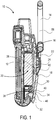
- the mounting system 10 may broadly include a battery cover 16 and one or more reciprocal mating elements 18.
- the battery cover 16 is operable to at least partially cover a battery receptacle 20 associated with the electronic device 12 and mate with at least one of the reciprocal mating elements 18.
- the reciprocal mating elements 18 may each be associated with one or more of the mounts 14 to enable the electronic device 12 to be secured to one or more of the mounts 14 by mating the battery cover 16 with a selected one of the reciprocal mating elements 18.
- Such a configuration enables the electronic device 12 to be easily secured to the various mounts 14 even if the mounts 14 present varying mounting configurations.
- the electronic device 12 may be any electronic device with the battery receptacle 20 or similar battery receptacle.
- the electronic device 12 may be a personal navigation device such as those manufactured by Garmin®.
- the electronic device 12 is not so limited and may include devices such as computing devices, personal media players, personal entertainment devices, televisions, radios, electronic monitoring devices, cameras, combinations thereof, and the like.
- the electronic device 12 may include various electronic and functional features, including for example, electronic displays, antennas, processing and memory elements, user input elements, microphones, speakers, electrical connectors, combinations thereof, and the like.
- the battery receptacle 20 associated with the electronic device 12 may be any receptacle operable to at least partially retain a power source such as one or more batteries.
- the battery receptacle 20 may be operable to retain battery elements presenting standard dimensions such as AA and AAA batteries and battery packs.
- the battery receptacle 20 may be operable to retain battery elements presenting any form or configuration.
- the battery receptacle 20 may retain a power source other than a battery.
- the battery receptacle 20 may include any elements operable to retain or transfer power, including wires, conduits, sockets, combinations thereof, and the like.
- the battery cover 16 may include any elements and present any configurations operable to couple with the electronic device 12 and mate with one or more of the reciprocal mating elements 18.
- the battery cover 16 includes a base 22 and a cover mating element 24 coupled thereto.
- the base 22 is operable to couple with a portion of the electronic device 12 and at least partially cover the battery receptacle 20.
- the battery cover 16 may comprise a portion of the electronic device 12 such that the base 22 is operable to couple with another portion, such as a main body, of the electronic device 12.
- the battery cover 16 and/or base 22 may be considered to be discrete from the electronic device 12.
- the battery cover 16 may be sold and/or distributed separately from the electronic device 12 to enable users to replace the original battery cover associated with the electronic device 12 with the battery cover 16.
- the base 22 may removably couple with the electronic device 12 utilizing various coupling elements such as screws, fasteners, latches, snaps, prongs, protrusions, slots, combinations thereof, and the like, to enable the power source retained by the battery receptacle 20 to be easily accessed and/or replaced.
- the base 22 may be slidably coupled with a rear portion of the electronic device 12 by sliding along a recess formed within the electronic device 12.
- the base 22 may present any configuration operable to couple with any portion of the electronic device 12 and the battery receptacle 20, including battery door configurations.
- the cover mating element 24 is operable to couple with the base 22 and interchangeably mate with one or more of the reciprocal mating elements 18 associated with the mounts 14.
- the cover mating element 24 may be integral or otherwise fixedly attached to the base 22.
- "operable to couple" as utilized herein includes configurations where the cover mating element 24 and base 22 are previously and/or permanently coupled together.
- the cover mating element 24 may be discrete from the base 22 and operable to be coupled therewith during and/or after assembly of the mounting system 10.
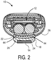
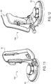
- the cover mating element 24 presents a plurality of protrusions 26 which extend therefrom. As illustrated in FIG. 2 , the protrusions 26 may extend from generally opposed sides of the cover mating element 24 to facilitate coupling with the reciprocal mating elements 18, as is discussed in more detail below.
- the cover mating element 24 and protrusions 26 present a generally T-shaped configuration where the base of the "T" is directly coupled to the base 22. The area between the base 22 and protrusions 26 defines a recess in which at least a portion of the reciprocal mating elements 18 is received.
- the protrusions 26 may extend substantially along the length of the cover mating element 24 to enable portions of the protrusions 26 to be easily received by the reciprocal mating elements 18. In some embodiments, the protrusions 26 may extend along only a portion of the cover mating element 24 to limit the length over which the cover mating element 24 and reciprocal mating elements 18 may be slidably coupled.
- the cover mating element 24 may include a stop that is positioned at a terminal end of the protrusions 26 to prevent the reciprocal mating elements 18 from sliding off the protrusions 26 after coupling.
- the cover mating element 24 may comprise a first portion 30, a second portion 32 hingedly coupled with the first portion 30, and a pocket portion 34 defined between the first and second portions 30, 32.
- the pocket portion 34 may be operable to receive at least portions of one of the reciprocal mating elements 18 to facilitate coupling of the cover mating element 24 and reciprocal mating elements 18.
- the portions 30, 32 are not necessarily hingedly coupled as in some embodiments the portions 30, 32 may be integrally formed and/or joined.
- the first portion 30 may include the protrusions 26 discussed above and be directly coupled with the base 22 of the battery cover 16.
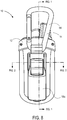
- the first portion 30 may be hingedly coupled with the second portion 32 at one of its terminal ends as is illustrated in FIG. 5 .
- the first portion 30 and second portion 32 may cooperate to form a hinge about which the second portion 32 may at least partially pivot to define the pocket portion 34.
- the base 22 may include one or more tabs 36 and a recess 38 that may be engaged by the first portion 30 to couple the first portion 30 and base 22 together without requiring the use of penetrating fastening elements that may affect the integrity of the base 22 and battery cover 16 and provide a leak path for water into the battery receptacle 20.
- the first portion 30 may include one or more contacts 40 that are operable to engage the tabs 36 and/or recess 38. For example, when the first portion 30 is slid against the base 22, the contacts 40 may engage the tabs 36 and recess 38 to quickly and securely affix the first portion 30 to the base 22 during and/or after initial assembly of the mounting system 10.
- the second portion 32 may be hingedly coupled to the first portion 30 or integral with the first portion 30 as discussed above.
- the second portion 32 may be directly coupled to the first portion 30 and not directly coupled to the base 22 to enable the second portion 32 to pivot about the first portion 30 when the first portion 30 is securely affixed to the base 22.
- the second portion 32 may present a tab-like configuration that presents a shorter length then the first portion 30 to facilitate pivoting.
- the first and second portions 30, 32 of the cover mating element 24 may be formed of any material to enable coupling with one or more of the reciprocal mating elements 18.
- the first and second portions 30, 32 may be formed of metal or other substantially durable materials to enable the battery cover 16 and one of the reciprocal mating elements 18 to remain mated even under adverse environmental and operational conditions.
- the first and second portion 30, 32 may additionally or alternatively be formed of plastic and other natural and synthetic materials.
- the pocket portion 34 is defined by the gap formed between the first and second portions 30, 32 where the portions 30, 32 are hingedly coupled. In embodiments where the first and second portions 30, 32 are integral, the pocket portion 34 is defined by a detent and/or aperture formed within the integral portions 30, 32.
- the pocket portion 34 may present any dimension or configuration based upon the configuration of the first and second portions 30, 32. In some embodiments, the first and second portions 30, 32 may be positioned to substantially eliminate the pocket portion 34 such that upon pivoting of the second portion 32 the pocket portion 34 is created. Thus, one or more dimensions of the pocket portion 34 may be varied through movement of the second portion 32.
- portions of the cover mating element 24 may be biased by a spring element 42 to facilitate proper definition of the pocket portion 34.
- the spring element 42 may bias the second portion 32 to limit the area provided by the pocket portion 34.
- the second portion 32 may pivot against the force provided by the spring element 42 to release the battery cover 16 from the electronic device 12, as is discussed in more detail below.
- a pivot pin 58 may be utilized in combination with the spring element 42 to hingedly couple the first portion 30 and second portion 32 together.
- the pivot pin 58 may be operable for insertion into the first portion 30 such that when the first portion 30 is coupled with the base 22 the pivot pin 58 will be at least partially enveloped by the base 22.
- the reciprocal mating elements 18 are each operable to couple with at least one of the mounts 14. In various embodiments, some of the reciprocal mating elements 18 may be integral with some of the mounts 14 while other reciprocal mating elements 18 may be operable to removably couple with some of the mounts 14. Each of the reciprocal mating elements 18 may present any configuration operable to interchangeably mate with the battery cover 16 and/or cover mating element 24.
- each of the reciprocal mating elements 18 may interchangeably mate with the cover mating element 24 by engaging the protrusions 26.
- each reciprocal mating element 18 may include grooves 44 that correspond to the protrusions 26 to enable slidable coupling with the cover mating element 24.
- the grooves 44 may at least partially receive the protrusions 26 while positioning a portion of the reciprocal mating element 18 between the base 22 and cover mating element 24.
- the protrusions 26 may be configured as grooves that include a protruding portion and the grooves 44 may be configured as protrusions that include a recess for receiving the protruding portions of the protrusions 26.
- both the protrusions 26 and grooves 44 may be substantially "C” shaped for interlocking.
- protrusion and “groove,” as utilized herein, refers to any structural configuration where any part of the protrusion may be received in any part of the groove, or vice versa.
- One or more of the reciprocal mating elements 18 may additionally or alternatively include a catch 46 operable to be at least partially received by the pocket portion 34 to couple the mating elements 18, 24 together.
- the catch 46 may be inserted into the pocket portion 34 to at least partially couple the mating elements 18, 24 together. Utilization of both the grooves 44 and catch 46 to mate the mating elements 18, 24 enables the mating elements 18, 24 to be easily and rapidly secured while preventing inadvertent decoupling, as discussed below in more detail.
- any of the reciprocal mating elements 18 may include any elements or present any configuration operable to interchangeably mate with the cover mating element 24.
- various reciprocal mating elements 18 may couple with selected mounts 14 by utilizing irremovable and removable mating elements such as fasteners, screws, clamps, clips, ball and socket joints, hook and loop fasteners, bolts, protrusions, straps, adhesives, combinations thereof, and the like.
- the mounts 14 may include any elements or combination of elements operable to secure the electronic device 12 to one or more surfaces.
- the mounts 14 may include an automobile mount, a motorcycle mount, a bicycle mount, a marine mount, a carrying case, and/or a carabineer mount.
- the mounts 14 may include any mount 14 operable to be associated with one or more of the reciprocal mating elements 18 and are not limited to the exemplary and/or illustrated mounts 14.
- At least one of the reciprocal mating elements 18 may include a socket mating element 18a, as is illustrated in FIG. 9 .
- the socket mating element 18a may include a socket 48 and a plurality of retaining arms 50 to removably couple with a ball associated with a ball-arm mount, such as an automobile or motorcycle mount. Utilization of the socket 48 and retaining arms 50 enables the socket mating element 18a to securely couple with various ball-arm mounting devices in a manner that enables the electronic device 12 to be easily repositioned and/or reoriented after coupling with the mount 14.
- At least one of the reciprocal mating elements 18 may include a cable mating element 18b that is operable to independently function as one or the mounts 14 and/or couple with one of the mounts 14.
- the cable mating element 18b may present a curved mounting surface 52 and one or more cable apertures 54.
- the curved mounting surface 52 is operable to abut a curved surface, such as a bicycle handlebar stem or frame structure, and be securely affixed thereto utilizing a cable inserted through one or more of the cable apertures 54.
- the cable mating element 18b may be operable to abut any curved or non-curved surfaces and does not necessarily include the curved mounting surface 52 to couple with curved bicycle surfaces.
- the cable mating element 18b may be utilized to secure the electronic device 12 to a user's wrist or forearm by abutting the cable mating element 18b against the user's wrist or forearm and securing the cable mating element 18b thereto utilizing a cable or other strap.
- At least one of the reciprocal mating elements 18 may include a carabineer mating element 18c that is operable to independently function as one or the mounts 14 and/or couple with one of the mounts 14.
- the carabineer mating element 18c may include or be coupled with a carabineer 56 to enable the electronic device 12 to be easily secured to various surfaces, such as backpacks, garments and apparel including belt loops, vests, and tool belts, hiking equipment, camping equipment, sporting equipment, vehicles including automobiles, motorcycles, and bicycles, combinations thereof, and the like.
- the carabineer 56 may be integral with the carabineer mating element 18c or operable for removable coupling therewith.
- the carabineer mating element 18c may include a latching element to enable the carabineer 56 to be selectively coupled therewith or the carabineer 56 may be permanently affixed to the carabineer mating element 18c.
- the carabineer 56 may present a loop-type configuration including a sprung or screwed gate to easily and quickly couple with various surfaces.
- the carabineer 56 may include any mating, locking, or coupling elements and is not limited to conventional carabineer configurations.
- At least one of the reciprocal mating elements 18 may include a marine mount mating element 18d that is operable to independently function as one or the mounts 14 and/or couple with one of the mounts 14.
- the marine mount mating element 18d may function as one of the mounts 14 to enable the electronic device 12 to be easily secured to various marine-related surfaces, such as marine equipment panels and the like.
- the marine mount mating element 18d may also releasably couple with a marine mount to enable the electronic device 12 and marine mount mating element 18d to be easily detached from the marine mount.
- the marine mount mating element 18d may include a backing support 60 including grooves 44 for interlocking with the protrusions 26 as discussed above.
- the backing support 60 may removably couple with a base 62 that is operable to couple with a marine-related surface.
- the base 62 may include removable and/or permanent mating elements, such as suction cups, magnetic elements, hook and loop fasteners, adhesives, fasteners, combinations thereof, and the like, the enable the base 62 to couple with marine-related surfaces.
- the backing support 60 may be integral with the base 62 and the marine mount mating element 18d and battery cover 16 may employ interlocking mating elements other than the protrusions 26 and grooves 44.
- At least one of the reciprocal mating elements 18 may include a carrying case mating element 18e that is operable to independently function as one or the mounts 14 and/or couple with one of the mounts 14.
- the carrying case mating element 18e may function as one of the mounts 14, such as by providing a carrying case for the electronic device 12, to which the electronic device 12 may be easily and securely attached by utilizing the reciprocal mating elements 18.
- the carrying case mating element 18e may also releasably couple with a carrying case mount to enable the electronic device 12 and carrying case mating element 18e to be easily detached from the carrying case.
- the carrying case mating element 18e may include a clip 64 including grooves 44 for interlocking with the protrusions 26 as discussed above.
- the clip 64 may be inserted into a carrying case (not illustrated) to enable the electronic device to be easily carried.
- the clip 64 may include one or more apertures 66 to enable the clip 64 to be securely coupled to the carrying case.
- the apertures 66 may receive cables, snaps, hooks, latches, buttons, and/or the like associated with the carrying case to prevent the clip 64-and electronic device 12-from inadvertently detaching from the carrying case.
- the clip 64 ensures that the electronic device 12 will stay securely coupled with the carrying case until the user detaches the electronic device 12 by sliding the protrusions 26 away from the grooves 44.
- the carrying case mating element 18e and battery cover 16 may employ reciprocal mating elements other than the protrusions 26 and grooves 44.
- the electronic device 12 may be utilized in various mounting configurations through the mating functionality provided by the battery cover 16.
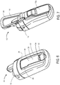
- the user may utilize the electronic device 12 in an unmounted configuration, as shown in FIG. 6 , by coupling the electronic device 12 and battery cover 16 together without the use of the reciprocal mating elements 18.
- the electronic device 12 may function as a handheld electronic device.
- the user may couple the battery cover 16 with a reciprocal mounting element associated with the automobile, such as the socket mating element 18a.
- a reciprocal mounting element associated with the automobile such as the socket mating element 18a.
- the user may couple the battery cover 16 with a reciprocal mating element associated with the bicycle, such as the cable mating element 18b.
- the user may decouple the battery cover 16 and cable mating element 18b and couple the battery cover 16 with a reciprocal mating element associated with the backpack, such as the carabineer mating element 18c.
- the user may mate the battery cover 16 with a selected one of the reciprocal mating elements 18 by utilizing the protrusions 26, pocket portion 34, grooves 44, and/or catch 46.
- the user may slide the grooves 44 of one of the reciprocal mating elements 18 around the protrusions 26 and slide the selected reciprocal mating element 18 upward until the catch 46 is received by the pocket portion 34 to securely couple the battery cover 16 to the selected reciprocal mating element 18.
- the user may lift the portion of the reciprocal mating element 18 associated with the catch 46 away from the pocket portion 34 and slide the reciprocal mating element 18 downward to enable a different reciprocal mating element 18 to be coupled with the battery cover 16.
- the user may easily mount and utilize the electronic device 12 in various mounting configurations by coupling the battery cover 16 with the various reciprocal mating elements 18 while not being required to manually reconfigure the battery cover 16 or electronic device 12 between mounting configurations. Further, utilization of the battery cover 16 for coupling with the reciprocal mating elements 18 may enable the various electronic and functional features of the electronic device 12, such as the display and user input elements, to remain unimpeded by the mating functionality provided by the cover mating element 24.
- Portions of the second portion 32 may be retained within a detent associated with the electronic device 12 to secure the battery cover 16 to the electronic device 12.
- the user may apply force to the second portion 32, against the biasing provided by the spring element 42, to decouple the second portion 32 from the detent and allow the removal of the battery cover 16 from the electronic device 12.
- portions of one or more of the reciprocal mating elements 18 may at least partially cover the second portion 32 when joined, as is illustrated in FIGS. 7-10 , to prevent movement of the second portion 32, and associated removal of the battery cover 16, when the electronic device 12 is secured to one of the mounts 14.
- Such a configuration enables the mounting system 10 be utilized with the mounts 14 in environments where the electronic device 12 may be exposed to significant forces and accelerations, without having the battery cover 16-and attached mount 14-accidentally decouple from the electronic device 12.
Landscapes
- Engineering & Computer Science (AREA)
- Mechanical Engineering (AREA)
- Radar, Positioning & Navigation (AREA)
- Remote Sensing (AREA)
- Chemical & Material Sciences (AREA)
- Chemical Kinetics & Catalysis (AREA)
- Electrochemistry (AREA)
- General Chemical & Material Sciences (AREA)
- Battery Mounting, Suspending (AREA)
Claims (14)
- Befestigungssystem zum Befestigen eines elektronischen Geräts (12), das eine Batterieaufnahme (20) aufweist, an einer Halterung (14), wobei das Befestigungssystem (10) aufweist:eine Batterieabdeckung (16), dieeine Basis (22), die betreibbar ist, um mit einem Teil des elektronischen Geräts zu koppeln und die Batterieaufnahme (20) zumindest teilweise abzudecken, undein Abdeckungspasselement (24) aufweist, das betreibbar ist, um mit der Basis (22) zu koppeln; undein wechselwirkendes Passelement (18), das der Halterung (14) zugeordnet ist, wobei das wechselwirkende Passelement (18) betreibbar ist, um austauschbar mit dem Abdeckungspasselement (24) zu koppeln, um es dem elektronischen Gerät (12) zu ermöglichen, an der Halterung (14) befestigt zu werden,wobei das Abdeckungspasselement (24) Vorsprünge (26) aufweist und das wechselwirkende Passelement (18) Vertiefungen (44) aufweist, die betreibbar sind, um die Vorsprünge (26) zumindest teilweise aufzunehmen, um es dem wechselwirkenden Passelement (18) und der Batterieabdeckung (16) zu ermöglichen, gleitend gekoppelt zu werden,wobei sich die Vorsprünge (26) von gegenüberliegenden Seiten des Abdeckungspasselements (24) erstrecken und das Abdeckungspasselement (24) und die Vorsprünge (26) eine T-förmige Konfiguration bilden, bei der die Basis des "T" unmittelbar mit der Basis (22) der Batterieabdeckung (16) gekoppelt ist und der Bereich zwischen der Basis (22) der Batterieabdeckung (16) und den Vorsprüngen (26) eine Aussparung definiert, in der beim gleitenden Verbinden zwischen dem wechselwirkenden Passelement (18) und der Batterieabdeckung (16) zumindest ein Teil des wechselwirkenden Passelements (18) aufgenommen wird.
- Befestigungssystem nach Anspruch 1, bei dem das System eine Vielzahl von wechselwirkenden Passelementen (18) aufweist, die einer Vielzahl von Halterungen (14) zugeordnet sind, wobei jedes der wechselwirkenden Passelemente (18) betreibbar ist, um mit dem Abdeckungspasselement (24) austauschbar zu koppeln, um es dem elektronischen Gerät (12) zu ermöglichen, an jeder der Halterungen (14) befestigt zu werden.
- Befestigungssystem nach Anspruch 2, bei dem ein erstes der wechselwirkenden Passelemente einer ersten Halterung zugeordnet ist und ein zweites der wechselwirkenden Passelemente einer zweiten Halterung zugeordnet ist, die von der ersten Halterung verschieden ist.
- Befestigungssystem nach Anspruch 3, bei dem die erste und die zweite Halterung Halterungen sind, die aus der Gruppe ausgewählt sind, die aus einer Kraftfahrzeughalterung, einer Motorradhalterung, einer Fahrradhalterung, einer Karabinerhalterung, einer Bootshalterung und einer Transportgehäusehalterung besteht.
- Befestigungssystem nach Anspruch 1, bei dem das wechselwirkende Passelement ein Rastelement aufweist und das Abdeckungspasselement eine ersten Abschnitt, einen zweiten Abschnitt und einen Vertiefungsabschnitt aufweist, der zwischen dem ersten und dem zweiten Abschnitt ausgebildet ist, wobei der Vertiefungsabschnitt betreibbar ist, um das Rastelement aufzunehmen, um die Passelemente miteinander zu koppeln.
- Befestigungssystem nach Anspruch 1, bei dem das wechselwirkende Passelement (18) einstückig mit der Halterung ausgebildet ist.
- Befestigungssystem nach Anspruch 1, bei dem die Basis (22) und das Abdeckungspasselement (24) fest verbunden sind.
- Verfahren zum Befestigen eines elektronischen Geräts, das eine Batterieaufnahmeaufweist, an einer Halterung, wobei das Verfahren aufweist:Koppeln einer Batterieabdeckung mit einem Teil des elektronischen Geräts, um die Batterieaufnahme zumindest teilweise abzudecken, wobei die Batterieabdeckung ein Abdeckungspasselement aufweist; undaustauschbares Koppeln des Abdeckungspasselements mit einem ersten wechselwirkenden Passelement, das der Halterung zugeordnet ist, wobeidas Abdeckungspasselement Vorsprünge aufweist und das erste wechselwirkende Passelement Vertiefungen aufweist, die betreibbar sind, um die Vorsprünge zumindest teilweise aufzunehmen, und die Passelemente gekoppelt werden, indem die Vorsprünge zumindest teilweise in die Vertiefungen geschoben werden,wobei die Vorsprünge (26) sich von gegenüberliegenden Seiten des Abdeckungspasselements (24) erstrecken und das Abdeckungspasselement (24) und die Vorsprünge (26) eine T-förmige Konfiguration bilden, bei der die Basis des "T" unmittelbar mit der Basis (22) der Batterieabdeckung (16) gekoppelt ist und der Bereich zwischen der Basis (22) der Batterieabdeckung (16) und den Vorsprüngen (26) eine Aussparung definiert, in der zumindest ein Teil des wechselwirkenden Passelements (18) beim gleitenden Koppeln zwischen dem wechselwirkenden Passelement (18) und der Batterieabdeckung (16) aufgenommen wird.
- Verfahren nach Anspruch 8, das des Weiteren aufweist, das Abdeckungspasselement und das erste wechselwirkende Passelement zu entkoppeln und das Abdeckungspasselement austauschbar mit einem zweiten wechselwirkenden Passelement zu koppeln, wobei das zweite wechselwirkende einer anderen Halterung als das erste wechselwirkende Passelement zugeordnet ist.
- Verfahren nach Anspruch 8, bei dem das erste wechselwirkende Passelement betreibbar ist, um mit mindestens einer Halterung zu koppeln, die aus der Gruppe ausgewählt ist, die aus einer Kraftfahrzeughalterung, einer Motorradhalterung, einer Fahrradhalterung, einer Karabinerhalterung, einer Bootshalterung und einer Transportgehäusehalterung besteht.
- Verfahren nach Anspruch 8, bei dem das erste wechselwirkende Passelement einstückig mit der Halterung ausgebildet ist.
- Verfahren nach Anspruch 8, bei dem das erste wechselwirkende Passelement ein Rastelement aufweist und das Abdeckungspasselement einen ersten Abschnitt, einen zweiten Abschnitt und einen Vertiefungsabschnitt aufweist, der zwischen dem ersten und dem zweiten Abschnitt ausgebildet ist, wobei die Passelemente durch Einführen von zumindest einem Teil des Rastelements in den Vertiefungsabschnitt gekoppelt werden.
- Befestigungssystem nach Anspruch 1, bei dem das wechselwirkende Passelement (18) eine Aufnahme (48) aufweist, die betreibbar ist, um entfernbar mit einer Kugel zu koppeln, die einer Kugelarmhalterung zugeordnet ist.
- Befestigungssystem nach Anspruch 1, bei dem das wechselwirkende Passelement (18) eine gekrümmte Befestigungsfläche (52) und eine oder mehrere Kabelöffnungen (66) aufweist.
Applications Claiming Priority (2)
| Application Number | Priority Date | Filing Date | Title |
|---|---|---|---|
| US11/874,236 US20090101766A1 (en) | 2007-10-18 | 2007-10-18 | Method, apparatus, and system for mounting an electronic device utilizing a battery cover |
| PCT/US2008/068131 WO2009051864A1 (en) | 2007-10-18 | 2008-06-25 | Method, apparatus and system for mounting an electronic device utilizing a batttery cover |
Publications (3)
| Publication Number | Publication Date |
|---|---|
| EP2201829A1 EP2201829A1 (de) | 2010-06-30 |
| EP2201829A4 EP2201829A4 (de) | 2015-12-02 |
| EP2201829B1 true EP2201829B1 (de) | 2017-11-29 |
Family
ID=40562488
Family Applications (1)
| Application Number | Title | Priority Date | Filing Date |
|---|---|---|---|
| EP08771887.0A Active EP2201829B1 (de) | 2007-10-18 | 2008-06-25 | Verfahren, vorrichtung und system zur anbringung einer elektronischen einrichtung unter verwendung einer batterieabdeckung |
Country Status (4)
| Country | Link |
|---|---|
| US (3) | US20090101766A1 (de) |
| EP (1) | EP2201829B1 (de) |
| CN (1) | CN101796897B (de) |
| WO (1) | WO2009051864A1 (de) |
Families Citing this family (8)
| Publication number | Priority date | Publication date | Assignee | Title |
|---|---|---|---|---|
| US8170790B2 (en) | 2006-09-05 | 2012-05-01 | Garmin Switzerland Gmbh | Apparatus for switching navigation device mode |
| US7987046B1 (en) * | 2007-04-04 | 2011-07-26 | Garmin Switzerland Gmbh | Navigation device with improved user interface and mounting features |
| US8477931B2 (en) | 2011-04-29 | 2013-07-02 | Hunter S. Thompson | Case for electronic device with surface for attaching building elements |
| CN103066221A (zh) * | 2011-10-19 | 2013-04-24 | 富泰华工业(深圳)有限公司 | 电子装置及其电池固定装置 |
| FR2983805B1 (fr) * | 2011-12-08 | 2014-01-31 | Parrot | Telecommande mixte filaire/sans-fil pour equipement multimedia et/ou de telephonie "mains-libres" de vehicule automobile. |
| US9723113B2 (en) | 2013-10-10 | 2017-08-01 | Pono Paani, Llc | Protective cover for electronic device with surface for attaching building elements |
| WO2024211124A1 (en) | 2023-04-03 | 2024-10-10 | Roadio, Inc. | Method and system for producing an environmental awareness for alerting an operator of a vehicle |
| WO2024211118A1 (en) | 2023-04-03 | 2024-10-10 | Roadio, Inc. | Method and system for providing a rider with a dynamic environmental awareness |
Family Cites Families (12)
| Publication number | Priority date | Publication date | Assignee | Title |
|---|---|---|---|---|
| US5540368A (en) * | 1991-08-30 | 1996-07-30 | Oliva; Ronald | Multi-purpose holster apparatus |
| JPH05267858A (ja) * | 1992-03-19 | 1993-10-15 | Sony Corp | 蓋開閉機構 |
| US5664292A (en) * | 1996-08-22 | 1997-09-09 | E Lead Electronic Co., Ltd. | Separable clip assembly |
| US5906031A (en) * | 1998-04-17 | 1999-05-25 | Hughes Electronics Corporation | Rotating and locking clip for portable electronic device |
| US5933330A (en) * | 1998-05-14 | 1999-08-03 | Motorola, Inc. | Portable radiotelephone arrangement having a battery pack and a detachable battery |
| KR100572526B1 (ko) * | 1998-12-18 | 2006-04-24 | 내셔날 몰딩 코오포레이션 | 다목적 부착 기구 |
| JP2002051126A (ja) * | 2000-08-02 | 2002-02-15 | Ichiro Ishizaki | 携帯電話の首掛けベルト係止装置 |
| US7077302B2 (en) * | 2001-12-10 | 2006-07-18 | Louis Chuang | Apparatus for selectively attaching a first object to a second object in a desired orientation |
| US6955279B1 (en) * | 2002-12-04 | 2005-10-18 | Garmin Ltd. | Carrying assembly and method for securement of electronic devices |
| US7079875B2 (en) * | 2003-12-19 | 2006-07-18 | Motorola, Inc. | Housing assembly with biased and removable door |
| US7757913B2 (en) * | 2005-04-25 | 2010-07-20 | Kyocera Corporation | Detachable belt clip interface mechanism for phone holsters and wireless phone holster assembly |
| KR20070071940A (ko) * | 2005-12-30 | 2007-07-04 | 브이케이 주식회사 | 착탈 가능한 이동통신 단말기 |
-
2007
- 2007-10-18 US US11/874,236 patent/US20090101766A1/en not_active Abandoned
-
2008
- 2008-06-25 US US12/146,266 patent/US20090101767A1/en not_active Abandoned
- 2008-06-25 WO PCT/US2008/068131 patent/WO2009051864A1/en not_active Ceased
- 2008-06-25 CN CN200880105387XA patent/CN101796897B/zh active Active
- 2008-06-25 EP EP08771887.0A patent/EP2201829B1/de active Active
-
2012
- 2012-05-21 US US13/476,798 patent/US8481190B2/en active Active
Non-Patent Citations (1)
| Title |
|---|
| None * |
Also Published As
| Publication number | Publication date |
|---|---|
| EP2201829A1 (de) | 2010-06-30 |
| EP2201829A4 (de) | 2015-12-02 |
| WO2009051864A1 (en) | 2009-04-23 |
| US20120231312A1 (en) | 2012-09-13 |
| US20090101766A1 (en) | 2009-04-23 |
| US8481190B2 (en) | 2013-07-09 |
| US20090101767A1 (en) | 2009-04-23 |
| CN101796897B (zh) | 2012-11-07 |
| CN101796897A (zh) | 2010-08-04 |
Similar Documents
| Publication | Publication Date | Title |
|---|---|---|
| US8481190B2 (en) | Method, apparatus, and system for mounting an electronic device | |
| US9900041B2 (en) | Accessory for use with housing for an electronic device | |
| US11653731B2 (en) | Device case with strap configurable for use with accessories | |
| US9450430B2 (en) | Mobile device mount which is wearable or may be used with a mounting system | |
| US7757913B2 (en) | Detachable belt clip interface mechanism for phone holsters and wireless phone holster assembly | |
| US6427293B1 (en) | Adhesive mounted device clip | |
| US5450993A (en) | Carry holder | |
| US5979724A (en) | Automobile universal dashboard mounting apparatus | |
| US20110240493A1 (en) | Self-aligning modular accessory storage system | |
| US6964361B2 (en) | Wireless device carrying apparatus and method | |
| US11737550B2 (en) | Attachment system for portable communication device | |
| US9605696B1 (en) | Detachable magnetic retainers | |
| US8534933B2 (en) | System for storing and releasing a camera for quick use | |
| US5458267A (en) | Sizeable attachment device | |
| CN215420376U (zh) | 一种移动电子件用可穿戴便携装置 | |
| CN215420384U (zh) | 用于molle系统战术背心的手机挂具 | |
| CN223924459U (zh) | 一种腕带支架 | |
| CN223391374U (zh) | 一种手机壳、拓展模块及手机壳组件 | |
| HK1125493A1 (en) | Connector retainers and methods of securing a connector in a receptacle | |
| CN120990902A (zh) | 扣夹以及风扇 | |
| JPH04170094A (ja) | 電子機器筐体のベルト掛け装置 | |
| TWM328154U (en) | Portable electronic device |
Legal Events
| Date | Code | Title | Description |
|---|---|---|---|
| PUAI | Public reference made under article 153(3) epc to a published international application that has entered the european phase |
Free format text: ORIGINAL CODE: 0009012 |
|
| 17P | Request for examination filed |
Effective date: 20100128 |
|
| AK | Designated contracting states |
Kind code of ref document: A1 Designated state(s): AT BE BG CH CY CZ DE DK EE ES FI FR GB GR HR HU IE IS IT LI LT LU LV MC MT NL NO PL PT RO SE SI SK TR |
|
| AX | Request for extension of the european patent |
Extension state: AL BA MK RS |
|
| RAP1 | Party data changed (applicant data changed or rights of an application transferred) |
Owner name: GARMIN SWITZERLAND GMBH |
|
| DAX | Request for extension of the european patent (deleted) | ||
| RA4 | Supplementary search report drawn up and despatched (corrected) |
Effective date: 20151029 |
|
| RIC1 | Information provided on ipc code assigned before grant |
Ipc: H05K 5/02 20060101AFI20151023BHEP |
|
| GRAP | Despatch of communication of intention to grant a patent |
Free format text: ORIGINAL CODE: EPIDOSNIGR1 |
|
| INTG | Intention to grant announced |
Effective date: 20170607 |
|
| GRAS | Grant fee paid |
Free format text: ORIGINAL CODE: EPIDOSNIGR3 |
|
| GRAA | (expected) grant |
Free format text: ORIGINAL CODE: 0009210 |
|
| AK | Designated contracting states |
Kind code of ref document: B1 Designated state(s): AT BE BG CH CY CZ DE DK EE ES FI FR GB GR HR HU IE IS IT LI LT LU LV MC MT NL NO PL PT RO SE SI SK TR |
|
| REG | Reference to a national code |
Ref country code: GB Ref legal event code: FG4D |
|
| REG | Reference to a national code |
Ref country code: CH Ref legal event code: EP |
|
| REG | Reference to a national code |
Ref country code: AT Ref legal event code: REF Ref document number: 951466 Country of ref document: AT Kind code of ref document: T Effective date: 20171215 |
|
| REG | Reference to a national code |
Ref country code: IE Ref legal event code: FG4D |
|
| REG | Reference to a national code |
Ref country code: DE Ref legal event code: R096 Ref document number: 602008053171 Country of ref document: DE |
|
| REG | Reference to a national code |
Ref country code: NL Ref legal event code: MP Effective date: 20171129 |
|
| REG | Reference to a national code |
Ref country code: LT Ref legal event code: MG4D |
|
| REG | Reference to a national code |
Ref country code: AT Ref legal event code: MK05 Ref document number: 951466 Country of ref document: AT Kind code of ref document: T Effective date: 20171129 |
|
| PG25 | Lapsed in a contracting state [announced via postgrant information from national office to epo] |
Ref country code: ES Free format text: LAPSE BECAUSE OF FAILURE TO SUBMIT A TRANSLATION OF THE DESCRIPTION OR TO PAY THE FEE WITHIN THE PRESCRIBED TIME-LIMIT Effective date: 20171129 Ref country code: NO Free format text: LAPSE BECAUSE OF FAILURE TO SUBMIT A TRANSLATION OF THE DESCRIPTION OR TO PAY THE FEE WITHIN THE PRESCRIBED TIME-LIMIT Effective date: 20180228 Ref country code: SE Free format text: LAPSE BECAUSE OF FAILURE TO SUBMIT A TRANSLATION OF THE DESCRIPTION OR TO PAY THE FEE WITHIN THE PRESCRIBED TIME-LIMIT Effective date: 20171129 Ref country code: FI Free format text: LAPSE BECAUSE OF FAILURE TO SUBMIT A TRANSLATION OF THE DESCRIPTION OR TO PAY THE FEE WITHIN THE PRESCRIBED TIME-LIMIT Effective date: 20171129 Ref country code: LT Free format text: LAPSE BECAUSE OF FAILURE TO SUBMIT A TRANSLATION OF THE DESCRIPTION OR TO PAY THE FEE WITHIN THE PRESCRIBED TIME-LIMIT Effective date: 20171129 |
|
| PG25 | Lapsed in a contracting state [announced via postgrant information from national office to epo] |
Ref country code: GR Free format text: LAPSE BECAUSE OF FAILURE TO SUBMIT A TRANSLATION OF THE DESCRIPTION OR TO PAY THE FEE WITHIN THE PRESCRIBED TIME-LIMIT Effective date: 20180301 Ref country code: AT Free format text: LAPSE BECAUSE OF FAILURE TO SUBMIT A TRANSLATION OF THE DESCRIPTION OR TO PAY THE FEE WITHIN THE PRESCRIBED TIME-LIMIT Effective date: 20171129 Ref country code: HR Free format text: LAPSE BECAUSE OF FAILURE TO SUBMIT A TRANSLATION OF THE DESCRIPTION OR TO PAY THE FEE WITHIN THE PRESCRIBED TIME-LIMIT Effective date: 20171129 Ref country code: LV Free format text: LAPSE BECAUSE OF FAILURE TO SUBMIT A TRANSLATION OF THE DESCRIPTION OR TO PAY THE FEE WITHIN THE PRESCRIBED TIME-LIMIT Effective date: 20171129 Ref country code: BG Free format text: LAPSE BECAUSE OF FAILURE TO SUBMIT A TRANSLATION OF THE DESCRIPTION OR TO PAY THE FEE WITHIN THE PRESCRIBED TIME-LIMIT Effective date: 20180228 |
|
| REG | Reference to a national code |
Ref country code: FR Ref legal event code: PLFP Year of fee payment: 11 |
|
| PG25 | Lapsed in a contracting state [announced via postgrant information from national office to epo] |
Ref country code: NL Free format text: LAPSE BECAUSE OF FAILURE TO SUBMIT A TRANSLATION OF THE DESCRIPTION OR TO PAY THE FEE WITHIN THE PRESCRIBED TIME-LIMIT Effective date: 20171129 |
|
| PG25 | Lapsed in a contracting state [announced via postgrant information from national office to epo] |
Ref country code: CZ Free format text: LAPSE BECAUSE OF FAILURE TO SUBMIT A TRANSLATION OF THE DESCRIPTION OR TO PAY THE FEE WITHIN THE PRESCRIBED TIME-LIMIT Effective date: 20171129 Ref country code: DK Free format text: LAPSE BECAUSE OF FAILURE TO SUBMIT A TRANSLATION OF THE DESCRIPTION OR TO PAY THE FEE WITHIN THE PRESCRIBED TIME-LIMIT Effective date: 20171129 Ref country code: CY Free format text: LAPSE BECAUSE OF FAILURE TO SUBMIT A TRANSLATION OF THE DESCRIPTION OR TO PAY THE FEE WITHIN THE PRESCRIBED TIME-LIMIT Effective date: 20171129 Ref country code: EE Free format text: LAPSE BECAUSE OF FAILURE TO SUBMIT A TRANSLATION OF THE DESCRIPTION OR TO PAY THE FEE WITHIN THE PRESCRIBED TIME-LIMIT Effective date: 20171129 Ref country code: SK Free format text: LAPSE BECAUSE OF FAILURE TO SUBMIT A TRANSLATION OF THE DESCRIPTION OR TO PAY THE FEE WITHIN THE PRESCRIBED TIME-LIMIT Effective date: 20171129 |
|
| REG | Reference to a national code |
Ref country code: DE Ref legal event code: R097 Ref document number: 602008053171 Country of ref document: DE |
|
| PG25 | Lapsed in a contracting state [announced via postgrant information from national office to epo] |
Ref country code: RO Free format text: LAPSE BECAUSE OF FAILURE TO SUBMIT A TRANSLATION OF THE DESCRIPTION OR TO PAY THE FEE WITHIN THE PRESCRIBED TIME-LIMIT Effective date: 20171129 Ref country code: IT Free format text: LAPSE BECAUSE OF FAILURE TO SUBMIT A TRANSLATION OF THE DESCRIPTION OR TO PAY THE FEE WITHIN THE PRESCRIBED TIME-LIMIT Effective date: 20171129 Ref country code: PL Free format text: LAPSE BECAUSE OF FAILURE TO SUBMIT A TRANSLATION OF THE DESCRIPTION OR TO PAY THE FEE WITHIN THE PRESCRIBED TIME-LIMIT Effective date: 20171129 |
|
| PLBE | No opposition filed within time limit |
Free format text: ORIGINAL CODE: 0009261 |
|
| STAA | Information on the status of an ep patent application or granted ep patent |
Free format text: STATUS: NO OPPOSITION FILED WITHIN TIME LIMIT |
|
| 26N | No opposition filed |
Effective date: 20180830 |
|
| PG25 | Lapsed in a contracting state [announced via postgrant information from national office to epo] |
Ref country code: SI Free format text: LAPSE BECAUSE OF FAILURE TO SUBMIT A TRANSLATION OF THE DESCRIPTION OR TO PAY THE FEE WITHIN THE PRESCRIBED TIME-LIMIT Effective date: 20171129 |
|
| REG | Reference to a national code |
Ref country code: CH Ref legal event code: PL |
|
| REG | Reference to a national code |
Ref country code: BE Ref legal event code: MM Effective date: 20180630 |
|
| REG | Reference to a national code |
Ref country code: IE Ref legal event code: MM4A |
|
| PG25 | Lapsed in a contracting state [announced via postgrant information from national office to epo] |
Ref country code: LU Free format text: LAPSE BECAUSE OF NON-PAYMENT OF DUE FEES Effective date: 20180625 Ref country code: MC Free format text: LAPSE BECAUSE OF FAILURE TO SUBMIT A TRANSLATION OF THE DESCRIPTION OR TO PAY THE FEE WITHIN THE PRESCRIBED TIME-LIMIT Effective date: 20171129 |
|
| PG25 | Lapsed in a contracting state [announced via postgrant information from national office to epo] |
Ref country code: IE Free format text: LAPSE BECAUSE OF NON-PAYMENT OF DUE FEES Effective date: 20180625 Ref country code: CH Free format text: LAPSE BECAUSE OF NON-PAYMENT OF DUE FEES Effective date: 20180630 Ref country code: LI Free format text: LAPSE BECAUSE OF NON-PAYMENT OF DUE FEES Effective date: 20180630 |
|
| PG25 | Lapsed in a contracting state [announced via postgrant information from national office to epo] |
Ref country code: BE Free format text: LAPSE BECAUSE OF NON-PAYMENT OF DUE FEES Effective date: 20180630 |
|
| PG25 | Lapsed in a contracting state [announced via postgrant information from national office to epo] |
Ref country code: MT Free format text: LAPSE BECAUSE OF NON-PAYMENT OF DUE FEES Effective date: 20180625 |
|
| PG25 | Lapsed in a contracting state [announced via postgrant information from national office to epo] |
Ref country code: TR Free format text: LAPSE BECAUSE OF FAILURE TO SUBMIT A TRANSLATION OF THE DESCRIPTION OR TO PAY THE FEE WITHIN THE PRESCRIBED TIME-LIMIT Effective date: 20171129 |
|
| PG25 | Lapsed in a contracting state [announced via postgrant information from national office to epo] |
Ref country code: PT Free format text: LAPSE BECAUSE OF FAILURE TO SUBMIT A TRANSLATION OF THE DESCRIPTION OR TO PAY THE FEE WITHIN THE PRESCRIBED TIME-LIMIT Effective date: 20171129 Ref country code: HU Free format text: LAPSE BECAUSE OF FAILURE TO SUBMIT A TRANSLATION OF THE DESCRIPTION OR TO PAY THE FEE WITHIN THE PRESCRIBED TIME-LIMIT; INVALID AB INITIO Effective date: 20080625 |
|
| PG25 | Lapsed in a contracting state [announced via postgrant information from national office to epo] |
Ref country code: IS Free format text: LAPSE BECAUSE OF FAILURE TO SUBMIT A TRANSLATION OF THE DESCRIPTION OR TO PAY THE FEE WITHIN THE PRESCRIBED TIME-LIMIT Effective date: 20180329 |
|
| PGFP | Annual fee paid to national office [announced via postgrant information from national office to epo] |
Ref country code: DE Payment date: 20250618 Year of fee payment: 18 |
|
| PGFP | Annual fee paid to national office [announced via postgrant information from national office to epo] |
Ref country code: GB Payment date: 20250620 Year of fee payment: 18 |
|
| PGFP | Annual fee paid to national office [announced via postgrant information from national office to epo] |
Ref country code: FR Payment date: 20250624 Year of fee payment: 18 |