US9450430B2 - Mobile device mount which is wearable or may be used with a mounting system - Google Patents

Mobile device mount which is wearable or may be used with a mounting system Download PDF

Info

Publication number
US9450430B2
US9450430B2 US14/216,184 US201414216184A US9450430B2 US 9450430 B2 US9450430 B2 US 9450430B2 US 201414216184 A US201414216184 A US 201414216184A US 9450430 B2 US9450430 B2 US 9450430B2
Authority
US
United States
Prior art keywords
mobile device
pair
claws
base plate
device mount
Prior art date
Legal status (The legal status is an assumption and is not a legal conclusion. Google has not performed a legal analysis and makes no representation as to the accuracy of the status listed.)
Expired - Fee Related, expires
Application number
US14/216,184
Other versions
US20150264825A1 (en
Inventor
Samuel Blake Fuller
Current Assignee (The listed assignees may be inaccurate. Google has not performed a legal analysis and makes no representation or warranty as to the accuracy of the list.)
SERENE LLC
Original Assignee
SERENE LLC
Priority date (The priority date is an assumption and is not a legal conclusion. Google has not performed a legal analysis and makes no representation as to the accuracy of the date listed.)
Filing date
Publication date
Application filed by SERENE LLC filed Critical SERENE LLC
Priority to US14/216,184 priority Critical patent/US9450430B2/en
Assigned to SERENE, LLC reassignment SERENE, LLC ASSIGNMENT OF ASSIGNORS INTEREST (SEE DOCUMENT FOR DETAILS). Assignors: FULLER, SAMUEL BLAKE
Publication of US20150264825A1 publication Critical patent/US20150264825A1/en
Application granted granted Critical
Publication of US9450430B2 publication Critical patent/US9450430B2/en
Expired - Fee Related legal-status Critical Current
Adjusted expiration legal-status Critical

Links

Images

Classifications

    • HELECTRICITY
    • H02GENERATION; CONVERSION OR DISTRIBUTION OF ELECTRIC POWER
    • H02JCIRCUIT ARRANGEMENTS OR SYSTEMS FOR SUPPLYING OR DISTRIBUTING ELECTRIC POWER; SYSTEMS FOR STORING ELECTRIC ENERGY
    • H02J7/00Circuit arrangements for charging or depolarising batteries or for supplying loads from batteries
    • H02J7/0042Circuit arrangements for charging or depolarising batteries or for supplying loads from batteries characterised by the mechanical construction
    • H02J7/0044Circuit arrangements for charging or depolarising batteries or for supplying loads from batteries characterised by the mechanical construction specially adapted for holding portable devices containing batteries
    • FMECHANICAL ENGINEERING; LIGHTING; HEATING; WEAPONS; BLASTING
    • F16ENGINEERING ELEMENTS AND UNITS; GENERAL MEASURES FOR PRODUCING AND MAINTAINING EFFECTIVE FUNCTIONING OF MACHINES OR INSTALLATIONS; THERMAL INSULATION IN GENERAL
    • F16BDEVICES FOR FASTENING OR SECURING CONSTRUCTIONAL ELEMENTS OR MACHINE PARTS TOGETHER, e.g. NAILS, BOLTS, CIRCLIPS, CLAMPS, CLIPS OR WEDGES; JOINTS OR JOINTING
    • F16B2/00Friction-grip releasable fastenings
    • F16B2/20Clips, i.e. with gripping action effected solely by the inherent resistance to deformation of the material of the fastening
    • F16B2/22Clips, i.e. with gripping action effected solely by the inherent resistance to deformation of the material of the fastening of resilient material, e.g. rubbery material
    • FMECHANICAL ENGINEERING; LIGHTING; HEATING; WEAPONS; BLASTING
    • F16ENGINEERING ELEMENTS AND UNITS; GENERAL MEASURES FOR PRODUCING AND MAINTAINING EFFECTIVE FUNCTIONING OF MACHINES OR INSTALLATIONS; THERMAL INSULATION IN GENERAL
    • F16MFRAMES, CASINGS OR BEDS OF ENGINES, MACHINES OR APPARATUS, NOT SPECIFIC TO ENGINES, MACHINES OR APPARATUS PROVIDED FOR ELSEWHERE; STANDS; SUPPORTS
    • F16M13/00Other supports for positioning apparatus or articles; Means for steadying hand-held apparatus or articles
    • F16M13/04Other supports for positioning apparatus or articles; Means for steadying hand-held apparatus or articles for supporting on, or holding steady relative to, a person, e.g. by chains, e.g. rifle butt or pistol grip supports, supports attached to the chest or head
    • GPHYSICS
    • G03PHOTOGRAPHY; CINEMATOGRAPHY; ANALOGOUS TECHNIQUES USING WAVES OTHER THAN OPTICAL WAVES; ELECTROGRAPHY; HOLOGRAPHY
    • G03BAPPARATUS OR ARRANGEMENTS FOR TAKING PHOTOGRAPHS OR FOR PROJECTING OR VIEWING THEM; APPARATUS OR ARRANGEMENTS EMPLOYING ANALOGOUS TECHNIQUES USING WAVES OTHER THAN OPTICAL WAVES; ACCESSORIES THEREFOR
    • G03B17/00Details of cameras or camera bodies; Accessories therefor
    • G03B17/56Accessories
    • G03B17/561Support related camera accessories
    • HELECTRICITY
    • H04ELECTRIC COMMUNICATION TECHNIQUE
    • H04MTELEPHONIC COMMUNICATION
    • H04M1/00Substation equipment, e.g. for use by subscribers
    • H04M1/02Constructional features of telephone sets
    • H04M1/04Supports for telephone transmitters or receivers
    • HELECTRICITY
    • H04ELECTRIC COMMUNICATION TECHNIQUE
    • H04MTELEPHONIC COMMUNICATION
    • H04M1/00Substation equipment, e.g. for use by subscribers
    • H04M1/02Constructional features of telephone sets
    • H04M1/11Supports for sets, e.g. incorporating armrests
    • HELECTRICITY
    • H05ELECTRIC TECHNIQUES NOT OTHERWISE PROVIDED FOR
    • H05KPRINTED CIRCUITS; CASINGS OR CONSTRUCTIONAL DETAILS OF ELECTRIC APPARATUS; MANUFACTURE OF ASSEMBLAGES OF ELECTRICAL COMPONENTS
    • H05K5/00Casings, cabinets or drawers for electric apparatus
    • H05K5/02Details
    • H05K5/0204Mounting supporting structures on the outside of casings
    • FMECHANICAL ENGINEERING; LIGHTING; HEATING; WEAPONS; BLASTING
    • F16ENGINEERING ELEMENTS AND UNITS; GENERAL MEASURES FOR PRODUCING AND MAINTAINING EFFECTIVE FUNCTIONING OF MACHINES OR INSTALLATIONS; THERMAL INSULATION IN GENERAL
    • F16MFRAMES, CASINGS OR BEDS OF ENGINES, MACHINES OR APPARATUS, NOT SPECIFIC TO ENGINES, MACHINES OR APPARATUS PROVIDED FOR ELSEWHERE; STANDS; SUPPORTS
    • F16M2200/00Details of stands or supports
    • F16M2200/08Foot or support base

Abstract

A mobile device mount includes a quadrilateral-shaped base plate having a pair of clamping sections at opposite corners. Each clamping section includes a pair of claws which extend away from the base plate, each claw ending in a gripper. The base plate may include several mounting features such as screw holes, channels, and twist-lock projections. The mobile device mount thereby provides convenient, secure, and versatile mounting for a mobile device.

Description

CROSS-REFERENCE TO RELATED APPLICATION
This application claims the benefit of provisional application No. 61/802,291, filed Mar. 15, 2013, the entire contents of which are incorporated by reference herein.
BACKGROUND OF THE INVENTION
1. Field of the Invention
The present disclosure is directed generally to a mount. More specifically, the present disclosure is directed to a mobile device mount having good securement and a high degree of versatility.
2. Description of Related Art
The rate of technological advancement in mobile electronic devices is extremely fast. With each round of improvements, mobile electronic devices incorporate faster processors, larger screens, and more powerful internal components. Each of these improvements in turn causes the mobile electronic device to require a larger power supply.
Simultaneously, there exists an increased demand for the miniaturization of mobile electronic devices. As a result of the increased power requirements of mobile electronic devices, internal batteries now often account for the majority of a mobile electronic device's form factor. As such, there is a limit, based on the required battery specifications, as to how compact the mobile electronic device may become.
Further still, as the proliferation of mobile electronic devices continue, many consumers own multiple mobile devices for personal and business use. As such, a typical consumer is in constant proximity with mobile electronic devices which may need charging on demand or at unscheduled times, or may be in constant need for a convenient mounting system, especially a system which may be mounted without the use of tools.
To solve this problem, there exists a growing field of mobile charging devices which are separate from the mobile electronic devices themselves. However, current mobile charging device suffer from several disadvantages.
First, because current mobile charging devices are separate from the devices they are intended to charge, power cords and the like are required to connect the two devices. When the two devices are not held in a fixed arrangement to one another, this cord can cause tangles and/or damage to the devices.
Second, many current mounting devices are limited to only one mounting configuration. In this manner, a user's options are limited when it comes to mounting devices such as cameras and the like.
As such, there exists a need for a mobile device mount that provides secure retainment and a versatile range of mounting configurations.
BRIEF SUMMARY OF THE INVENTION
To solve the above problems, various aspects of the present disclosure include a base plate and first and second clamping sections to hold a mobile device therebetween.
Additionally, various aspects of the present disclosure include one or more mounting features to provide additional mounting configurations.
Additionally, various aspects of the present disclosure include a mobile device held by one or more mobile device mounts. Alternatively, various aspects of the present disclosure include multiple mobile devices held by a single mobile device mount.
DESCRIPTION OF THE DRAWINGS
FIG. 1A is a top perspective view of an exemplary mobile device mount according to various aspects of the present disclosure.
FIG. 1B is bottom perspective view of the exemplary mobile device mount of FIG. 1A.
FIG. 2A is a side view of the exemplary mobile device mount of FIGS. 1A-B.
FIG. 2B is a top view of the exemplary mobile device mount of FIGS. 1A-B.
FIG. 3 is partial view of the exemplary mobile device mount of FIGS. 1A-B.
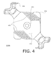
FIG. 4 is a top view of a second exemplary mobile device mount according to various aspects of the present disclosure.
FIG. 5 is a perspective view of a third exemplary mobile device mount according to various aspects of the present disclosure.
FIG. 6A is a first exemplary mounting configuration according to various aspects of the present disclosure.
FIG. 6B is a second exemplary mounting configuration according to various aspects of the present disclosure.
FIG. 7 illustrates an exemplary dual-mounting configuration according to various aspects of the present disclosure.
FIG. 8 illustrates an exemplary wall charger configuration according to various aspects of the present disclosure.
DETAILED DESCRIPTION
In the following description, for purposes of explanation, numerous details are set forth, such as system configurations, to provide an understanding of one or more embodiments. However, it is and will be apparent to one skilled in the art that these specific details are not necessarily required to practice various aspects of the present disclosure.
A mobile device mount according to various aspects of the present disclosure is configured to allow for affixing a mobile device to a person or animal (“wearable” configurations) or an inanimate object (“mountable” configurations). Additionally or alternatively, a mobile device mount according to various aspects of the present disclosure is configured to affix inanimate objects to the mobile device.
In one aspect of the present disclosure, the mobile device mount may be configured to grasp a mobile device and thereby provide a mounting surface thereto.
In use, a mobile device mount is configured to attach to a mobile device (not shown). In one exemplary aspect of the present disclosure, the mobile device is a mobile Li-ion battery. In another exemplary aspect of the present disclosure, the mobile device may be a computing device, such as a cellular phone, a smartphone, a still camera, a video camera, a Global Positioning System (GPS) device, and the like. In general, the computing device may be any computing system and/or device that includes a processor and a memory. The computing device may employ any of a number of computer operating systems, including but not limited to versions and/or varieties of the Windows® operating system distributed by Microsoft Corp. of Redmond, Wash.; the Unix operating system (e.g., the Solaris® operating system distributed by Oracle Corporation of Redwood Shores, Calif.); the AIX UNIX operating system distributed by International Business Machines of Armonk, N.Y.; the Linux operating system; the Mac OS X and iOS operating systems distributed by Apple Inc. of Cupertino, Calif.; the BlackBerry OS distributed by Research In Motion of Waterloo, Canada; and the Android operating system developed by the Open Handset Alliance. Preferably, the mobile device has a form factor of a substantially rectangular prism.
One example of a mounting arrangement for the mobile device may be an arrangement comprising a pair of mobile device mounts configured to jointly encompass the mobile device while permitting access to any ports disposed in a side surface of the mobile device.
In this configuration, the bottom mobile device mount may be configured to mount into existing or custom mounting systems, whereas the top mobile device mount may be configured to mount into existing or custom mounting cradles for a second mobile device. For example, the pair of mobile device mounts may jointly encompass a mobile Li-ion battery, and the top mobile device mount may further be configured to mount a camera powered by the mobile Li-ion battery.
Additionally or alternatively, in this configuration, the jointly-encompassed mobile device may be disposed to “interrupt” existing or custom mounting systems for devices; for example, an existing or custom mounting system for the second mobile device may be instead attached to the bottom mobile device mount.
In order to provide sufficient securement of the mobile device, the mobile device mount is appropriately dimensioned to match the outer dimensions of the mobile device as will be described in more detail below.
FIGS. 1A-3 illustrate an exemplary mobile device mount 100 according to various aspects of the present disclosure.
FIG. 1A shows a top perspective view of the exemplary mobile device mount 100, FIG. 1B shows a bottom perspective view thereof, FIG. 2A shows a side view thereof, and FIG. 2B shows a top view thereof. Mobile device mount 100 includes a quadrilateral base plate having an abutment surface 101 and a mounting surface 102, a first clamping section 103, and a second clamping section 104. Preferably, mobile device mount 100 has a unitary construction formed by, for example, injection molding.
Mobile device mount 100 is preferably formed from a material having high resilience, high shear and tensile strengths, and good deflection, while retaining sufficient flexibility to allow the mobile device mount 100 to snap onto a mobile device. Most preferably, mobile device mount 100 is formed from a plastic such as polycarbonate/acrylonitrile butadiene styrene (“PC/ABS”) or poly(hexane-6-lactam) (“PA6”).
Abutment surface 101 and mounting surface 102 are respectively disposed as opposite surfaces of the base plate. In use, abutment surface 101 is configured to at least partly abut a surface of a mobile device being held, such as a mobile device of the type described above. Furthermore, mounting surface 102 is configured to provide a support surface for an external device, such as a second mobile device of the type described above. In this aspect of the present disclosure, abutment surface 101 and mounting surface 102 are substantially planar. Alternatively, if the mobile device to which mobile device mount 100 is configured has a slightly convex surface, abutment surface 101 may provide a matching concave surface. Additionally, mounting surface 102 may be configured with a frictional subsurface thereof. In this manner, mounting surface 102 may prevent rotation in an object in contact therewith.
The first and second clamping sections 103, 104 are respectively disposed at a first corner and a second corner of the base plate, where the first corner and the second corner are disposed opposite one another. In use, the first and second clamping sections 103, 104 respectively clamp a corresponding first corner and second corner of a mobile device. As such, mobile device mount 100 is preferably configured such that a distance between the first clamping section 103 and the second clamping section 104 is matched to a diagonal dimension of the mobile device. First and second clamping sections 103, 104 respectively extend away from the base plate in a direction perpendicular to the plane of the base plate.
As illustrated in FIGS. 2A-B, each of first and second clamping sections 103, 104 are respectively configured to clamp on two surfaces of a held device near the corner thereof. In this manner, mobile device mount 100 can provide a secure grip on all four side surfaces of a rectangular-prism-shaped mobile device while having a small footprint. In other words, each clamping section 103, 104 respectively provides for grip on both axes of the plane of the base plate.
FIG. 3 shows a detailed view of an exemplary clamping section, such as first clamping section 103 or second clamping section 104. Exemplary clamping section 103, 104 includes a proximate portion 300 disposed at a corner of the base plate and a distal portion 303 disposed a distance from the base plate, a claw having an outer surface 301 and an inner surface 302 extending therebetween. Although FIG. 3 illustrates outer surface 301 as a convex surface and inner surface 302 as a concave surface, one or both of surfaces 301, 302 may alternatively have a planar shape. In either configuration, respective corners between outer surface 301, the proximate portion 300, and the distal portion 303 are rounded. Preferably, the claws are reinforced so as to transfer torque to the base plate.
Clamping section 103, 104 terminates at the distal portion 303 with a gripper 303 a. Gripper 303 a extends substantially perpendicularly to outer surface 301 and inner surface 302, and in a direction parallel to a plane of the base plate of mobile device mount 100. In this manner, the surface of gripper 303 a provides a frictional clamping on an outer surface of a mobile device held by mobile device mount 100. As such, in coordination with abutment surface 101 and inner surface 302, gripper 303 a allows for secure contact with a rectangular prism-shaped-device on all six surfaces thereof.
Preferably, each clamping section 103, 104 respectively includes a single proximate section and a pair of claws extending perpendicular to both the base plate and one another, each claw terminating at a gripper.
Preferably, the frictional clamping provided by clamping sections 103, 104 is sufficient to withstand pulling forces of greater than fifty times the weight of the mobile device being clamped.
FIG. 4 illustrates a second exemplary mobile device mount 100A according to a second aspect of the present disclosure. For clarity of disclosure, those elements of second exemplary mobile device mount 100A which are substantially similar to mobile device mount 100 are not expressly labeled in FIG. 4. Similar to mobile device mount 100, mobile device mount 100A includes a base plate having an abutment surface 101 and a mounting surface 102, a first clamping section 103, and a second clamping section 104.
Mobile device mount 100A further includes a plurality of mounting features such as a through-hole 401, a channel 402, a retention tab 403, a twist-lock projection 404, and ridges 405. Although FIG. 4 illustrates exemplary mobile device mount 100A as including all of the above mounting features, mobile device mount 100A (and/or mobile device mount 100) may include fewer or additional mounting features.
Through-hole 401 passes from abutment surface 101 to mounting surface 102. Preferably, the diameter of through-hole 401 at abutment surface 101 is larger than the diameter of through-hole 401 at mounting surface 102. Furthermore, the diameter of the through-hole 401 at mounting surface 102 is preferably about 0.25 in. In this manner, through-hole 401 can accommodate a standard ¼-20 screw (or another common mounting screw) such that the screw head remains flush with abutment surface 101.
Channel 402 is a recessed surface portion of abutment surface 101. Preferably, a width of channel 401 is at least 0.75 in and a depth of channel 401 is less than 0.125 in. Channel 402 extends from a first edge of the base plate to a second edge opposite the first edge. In this manner, channel 402 can accommodate a strap, a belt, a cord, a wristband, and the like. As illustrated in FIG. 4, exemplary mobile device mount 100A preferably has two channels, where a first channel runs in a direction from the first clamping section to the second clamping section and a second channel runs in a direction perpendicular to a side surface of the base plate.
Retention tab 403 extends from at least one claw of the clamping sections 103, 104 in a direction perpendicular thereto (that is, parallel to the base plane). Retention tab 403 has a substantially concave inner surface. In use, retention tab 403 is configured to securely hold a cord (such as a power cord or a USB cord) in place between the concave inner surface and an outer surface of a held mobile device. In this manner, retention tab 403 may provide a secure hold and relieve tension on a held cord. As illustrated in FIG. 4, exemplary mobile device mount 100A preferably has two retention tabs disposed opposite one another.
Twist-lock projection 404 extends from the base plate in a direction parallel to a plane of the base plate, and preferably has the same or a smaller thickness than a thickness of the base plate. In this manner, twist-lock projection 404 allows the mobile device mount 100A to be securely attached to accessory plates having a female twist-lock adaptor. Examples of such accessory plates include wall chargers (such as a wall charger of the type described in more detail below), two-prong adaptors for an existing mount system (such as a GoPro® mount system), three-prong adaptors for a camera (such as a GoPro® camera), belt clips, RAM mounts, tripod mounts, suction mounts, push-pull pin clamps for insertion into flat surfaces, wraps, or ties for cylindrical surfaces. As illustrated in FIG. 4, exemplary mobile device mount 100A preferably has two twist-lock projections disposed opposite one another.
Ridges 405 extend along channels 402 and, in combination therewith, provide abutment surface 101. Ridges 405 are configured to provide friction to either a held mobile device or to any intervening element, such as a strap or belt. In this manner, ridges 405 may work in tandem with channels 402 to provide slidable engagement in a first direction, but secure engagement in a second direction perpendicular to the first direction.
FIG. 5 illustrates a secondary mount 500 to be used with mobile device mount 100A. Specifically, secondary mount comprises a secondary plate 501 and a pair of female twist-lock adaptors 502. Secondary mount 500 is configured to be engaged with mobile device mount 100A via a rotatable mating between twist-lock projections 404 and female twist-lock adaptors 502. Secondary mount 500 may be configured to provide a secondary mount surface as described above. Additionally, secondary plate 501 may be further configured with a second pair of female twist-lock adaptors 502 on an opposite face thereof.
FIGS. 6A-B illustrate first and second mounting configurations for mobile device mount 100A. Specifically, FIG. 6A illustrates a configuration wherein mobile device mount 100A is configured to receive a strap 601 (such as a belt, a backpack strap, or any other flexible attachment surface) through channel 402. FIG. 6B illustrates a configuration wherein mobile device mount 100A is configured to receive a fastener 602 (such as a screw) in through-hole 401. In this manner, FIGS. 6A-B illustrate exemplary means by which mobile device mount 100A may be mounted to a surface, a person, or any other animate or inanimate object.
FIG. 7 illustrates a usage example. Specifically, FIG. 7 illustrates a first mobile device 701 (such as a portable battery) being encompassed by a pair of mobile device mounts 100A. Upper mobile device mount 100A is configured to attach the first mobile device 701 to a second mobile device 702 (such as a portable camera). Second mobile device 702 may preferably be attached to upper mobile device mount 100A by mounting features such as features 401-404 described above.
FIG. 8 illustrates an exemplary wall charger configuration for exemplary mobile device mount 100 (or 100A). FIG. 8 illustrates a mobile device mount 100, 100A attached to a mobile device 701 (such as the portable battery described above with regard to FIG. 7). On a mounting surface 102 of mobile device mount 100, 100A, a wall charger 801 is provided. Wall charger may preferably be attached to mobile device mount 100A by mounting features such as features 401-404 described above.
Wall charger 801 includes a frame, a device plug 802, and a wall plug 803. Device plug 802 is configured to engage with the held mobile device 701 to provide charging power thereto. As particularly illustrated in FIG. 8, wall plug 803 is a standard two-prong adaptor; however, other types of wall plugs may be provided to adapt to other countries and/or power sources.
Although not expressly illustrated, various aspects of the present disclosure include other mounting configurations as described below.
In a bicycle mount configuration, a clamp may be employed around a head tube or a seat tube to encompass one of the tubes, and a mobile device mount may be attached thereto to hold a mobile device in place. Similarly, this type of clamping may be applied to roll cages, handlebars, or any tubular component such as a vehicle part, sports equipment, commercial equipment, and/or industrial equipment.
In a RAM mount configuration, mobile device mount may be configured to hold and/or attach to a motorbike RAM mount. Additionally or alternatively, multiple mobile device mounts 100 may be provided so that a first mobile device mount is mounted to the RAM mount, and a second mobile device mount has a mounting surface which provides a second RAM mount for mounting additional mobile devices.
In a cupholder mount configuration, mobile device mount may be dimensioned so as to fit into an automobile cupholder.
In a camera mount configuration, a mobile device mount may be configured to provide mounting surface 102 for direct mounting of a camera, such as a GoPro® Camera, or a preexisting mounting kit system therefor.
In a vacuum mount configuration, a mobile device mount may be configured with a suction cup or the like to provide for mounting to a variety of surfaces regardless of surface orientation. In this manner, the mobile device mount may be configured for a variety of different devices, including cellular phones or other electronic items having a flat surface.
With regard to any processes, systems, methods, heuristics, etc. described herein, it should be understood that, although the steps of such processes, etc. have been described as occurring according to a certain ordered sequence, such processes could be practiced with the described steps performed in an order other than the order described herein. It further should be understood that certain steps could be performed simultaneously, that other steps could be added, or that certain steps described herein could be omitted. In other words, the descriptions of processes herein are provided for the purpose of illustrating certain embodiments, and should in no way be construed so as to limit the claims.
Accordingly, it is to be understood that the above description is intended to be illustrative and not restrictive. Many embodiments and applications other than the examples provided would be apparent upon reading the above description. The scope should be determined, not with reference to the above description, but should instead be determined with reference to the appended claims, along with the full scope of equivalents to which such claims are entitled. It is anticipated and intended that future developments will occur in the technologies discussed herein, and that the disclosed systems and methods will be incorporated into such future embodiments. In sum, it should be understood that the application is capable of modification and variation.
All terms used in the claims are intended to be given their broadest reasonable constructions and their ordinary meanings as understood by those knowledgeable in the technologies described herein unless an explicit indication to the contrary in made herein. In particular, use of the singular articles such as “a,” “the,” “said,” etc. should be read to recite one or more of the indicated elements unless a claim recites an explicit limitation to the contrary.
The Abstract of the Disclosure is provided to allow the reader to quickly ascertain the nature of the technical disclosure. It is submitted with the understanding that it will not be used to interpret or limit the scope or meaning of the claims. In addition, in the foregoing Detailed Description, it can be seen that various features are grouped together in various embodiments for the purpose of streamlining the disclosure. This method of disclosure is not to be interpreted as reflecting an intention that the claimed embodiments require more features than are expressly recited in each claim. Rather, as the following claims reflect, inventive subject matter lies in less than all features of a single disclosed embodiment. Thus the following claims are hereby incorporated into the Detailed Description, with each claim standing on its own as a separately claimed subject matter.

Claims (20)

The invention claimed is:
1. A mobile device mount, comprising:
a base plate including an abutment face and a mounting face;
a first clamping section, including
a first proximate section disposed at a first corner of the base plate,
a first pair of claws extending from the first proximate section in a first direction, the first direction being perpendicular to the base plate, and
a first pair of grippers respectively disposed at a distal end of the first pair of claws and extending in a second direction and a third direction, respectively, the second and third directions being parallel to the base plate; and
a second clamping section, including
a second proximate section disposed at a second corner of the base plate, the second corner being located opposite the first corner,
a second pair of claws extending from a second corner of the base plate in the first direction, and
a second pair of grippers respectively disposed at a distal end of the second pair of claws and extending in a fourth direction and fifth direction, respectively, the fourth and fifth directions being parallel to the base plate,
wherein:
a length of each of the first pair of claws in the first direction is greater than a width and a depth of each of the first pair of claws;
the length of each of the first pair of claws in the first direction is greater than a length of each of the first pair of grippers in the respective second and third directions, respectively;
a length of each of the second pair of claws in the first direction is greater than a width and a depth of each of the second pair of claws; and
the length of each of the second pair of claws in the first direction is greater than a length of each of the second pair of grippers in the respective third and fourth directions, respectively.
2. The mobile device mount according to claim 1, wherein the base plate includes a screw hole at a center portion thereof.
3. The mobile device mount according to claim 2, wherein the screw hole has a diameter of 0.25in.
4. The mobile device mount according to claim 2, wherein a diameter of the screw hole at the abutment surface is larger than a diameter of the screw hole at the mounting surface.
5. The mobile device mount according to claim 1, wherein the abutment face of the base plate includes a channel with a width of at least 0.75 inches.
6. The mobile device mount according to claim 1, where a claw of the first pair of claws further includes a retention tab on a side surface thereof.
7. The mobile device mount according to claim 1, wherein the base plate includes a twist-lock projection.
8. The mobile device mount according to claim 1, wherein the mobile device mount is formed of a material selected from the group including polycarbonate/acrylonitrile butadiene styrene and poly (hexane-6-lactam).
9. The mobile device mount of claim 1, wherein the base plate has a substantially quadrilateral shape.
10. The mobile device mount of claim 9, wherein the baseplate has a substantially square shape.
11. The mobile device mount of claim 1, wherein at least the first clamping section, the second clamping section, and the baseplate are of a unitary construction.
12. A mounted mobile device, comprising:
a mobile device; and
a mobile device mount, the mobile device mount including:
a base plate including an abutment face and a mounting face;
a first clamping section, including
a first proximate section disposed at a first corner of the base plate,
a first pair of claws extending from the first proximate section in a first direction, the first direction being perpendicular to the base plate, and
a first pair of grippers respectively disposed at a distal end of the first pair of claws and extending in a second direction and a third direction, respectively, the second and third directions being parallel to the base plate; and
a second clamping section, including
a second proximate section disposed at a second corner of the base plate, the second corner being located opposite the first corner,
a second pair of claws extending from a second corner of the base plate in the first direction, and
a second pair of grippers respectively disposed at a distal end of the second pair of claws and extending in a fourth direction and fifth direction,
respectively, the fourth and fifth directions being parallel to the base plate,
wherein:
a length of each of the first pair of claws in the first direction is greater than a width and a depth of each of the first pair of claws;
the length of each of the first pair of claws in the first direction is greater than a length of each of the first pair of grippers in the respective second and third directions, respectively;
a length of each of the second pair of claws in the first direction is greater than a width and a depth of each of the second pair of claws; and
the length of each of the second pair of claws in the first direction is greater than a length of each of the second pair of grippers in the respective third and fourth directions, respectively.
13. The mounted mobile device according to claim 12, wherein the mobile device is a mobile phone.
14. The mounted mobile device according to claim 12, wherein the mobile device is a mobile battery.
15. The mounted mobile device according to claim 12, wherein the mobile device is a camera.
16. The mobile device mount of claim 12, wherein the base plate has a substantially quadrilateral shape.
17. The mobile device mount of claim 12, wherein the baseplate has a substantially square shape.
18. The mobile device mount of claim 12, wherein at least the first clamping section, the second clamping section, and the baseplate are of a unitary construction.
19. A mounted mobile device, comprising:
a mobile device;
a first mobile device mount on a first face of the mobile device; and
a second mobile device mount on a second face of the mobile device, the second face opposite the first face,
wherein the first and second mobile device mount respectively comprise:
a base plate including an abutment face and a mounting face;
a first clamping section, including
a first proximate section disposed at a first corner of the base plate,
a first pair of claws extending from the first proximate section in a first direction, the first direction being perpendicular to the base plate, and
a first pair of grippers respectively disposed at a distal end of the first pair of claws and extending in a second direction and a third direction, respectively, the second and third directions being parallel to the base plate; and
a second clamping section, including
a second proximate section disposed at a second corner of the base plate, the second corner being located opposite the first corner,
a second pair of claws extending from a second corner of the base plate in the first direction, and
a second pair of grippers respectively disposed at a distal end of the second pair of claws and extending in a fourth direction and fifth direction, respectively, the fourth and fifth directions being parallel to the base plate,
wherein:
a length of each of the first pair of claws in the first direction is greater than a width and a depth of each of the first pair of claws;
the length of each of the first pair of claws in the first direction is greater than a length of each of the first pair of grippers in the respective second and third directions, respectively;
a length of each of the second pair of claws in the first direction is greater than a width and a depth of each of the second pair of claws; and
the length of each of the second pair of claws in the first direction is greater than a length of each of the second pair of grippers in the respective third and fourth directions, respectively.
20. The mobile device mount of claim 19, wherein at least the first clamping section, the second clamping section, and the baseplate are of a unitary construction.
US14/216,184 2013-03-15 2014-03-17 Mobile device mount which is wearable or may be used with a mounting system Expired - Fee Related US9450430B2 (en)

Priority Applications (1)

Application Number Priority Date Filing Date Title
US14/216,184 US9450430B2 (en) 2013-03-15 2014-03-17 Mobile device mount which is wearable or may be used with a mounting system

Applications Claiming Priority (2)

Application Number Priority Date Filing Date Title
US201361802291P 2013-03-15 2013-03-15
US14/216,184 US9450430B2 (en) 2013-03-15 2014-03-17 Mobile device mount which is wearable or may be used with a mounting system

Publications (2)

Publication Number Publication Date
US20150264825A1 US20150264825A1 (en) 2015-09-17
US9450430B2 true US9450430B2 (en) 2016-09-20

Family

ID=54070031

Family Applications (2)

Application Number Title Priority Date Filing Date
US14/216,184 Expired - Fee Related US9450430B2 (en) 2013-03-15 2014-03-17 Mobile device mount which is wearable or may be used with a mounting system
US14/216,167 Abandoned US20170163062A9 (en) 2013-03-15 2014-03-17 Wearable / mountable mobile charging device

Family Applications After (1)

Application Number Title Priority Date Filing Date
US14/216,167 Abandoned US20170163062A9 (en) 2013-03-15 2014-03-17 Wearable / mountable mobile charging device

Country Status (1)

Country Link
US (2) US9450430B2 (en)

Cited By (4)

* Cited by examiner, † Cited by third party
Publication number Priority date Publication date Assignee Title
US9942998B1 (en) * 2017-04-06 2018-04-10 Flight Level Design Partners, LLC Electronic mobile device holder
US10180207B1 (en) * 2017-07-13 2019-01-15 Danylo Kozub Stand
US10376020B1 (en) * 2015-01-05 2019-08-13 Mars, Incorporated Redundant retention of a removable device
US10420401B2 (en) 2013-03-29 2019-09-24 Mars, Incorporated Pet health monitor with collar attachment and charger

Families Citing this family (18)

* Cited by examiner, † Cited by third party
Publication number Priority date Publication date Assignee Title
US9515500B2 (en) * 2014-07-08 2016-12-06 Goal Zero Llc Portable energy storage and power supply system
US20150003907A1 (en) * 2014-07-23 2015-01-01 Jeffrey Overall Device for connecting portable electronic devices to cameras
USD757647S1 (en) * 2015-01-20 2016-05-31 Robert George Engel Charging station
USD758965S1 (en) * 2015-02-03 2016-06-14 Jerry Jen Charging adapter
JP1559171S (en) * 2016-01-28 2016-09-20
USD830971S1 (en) * 2016-02-04 2018-10-16 Emw Co., Ltd. Wireless charger
US10873205B2 (en) * 2017-08-25 2020-12-22 Soutono LLC Detachable surface mounting utility hub
KR200491833Y1 (en) * 2018-11-12 2020-06-12 주식회사 라미인터내셔널 Supporter for mobile phone and camera
CN109246276B (en) * 2018-11-21 2024-03-12 宁波钜锋电子科技有限公司 Support capable of rapidly loading and unloading objects with different sizes
USD912621S1 (en) * 2019-08-01 2021-03-09 Shenzhen Kai Xing Hui Technology Co., Ltd. Multi-port charger
USD939325S1 (en) * 2019-10-11 2021-12-28 John F. Bently Mounting holder
USD927421S1 (en) * 2020-03-04 2021-08-10 Shenzhen Nearbyexpress Technology Development Company Limited Charger
USD920906S1 (en) * 2020-03-26 2021-06-01 Lianfang Qiu Charger
USD941240S1 (en) * 2020-07-03 2022-01-18 Shenzhen Merpower Electronic Co, Ltd Power bank
USD964928S1 (en) * 2020-10-01 2022-09-27 Vector Products, Inc. Power supply
JP1708284S (en) * 2021-07-06 2022-02-25 Wireless transmitter
USD1011285S1 (en) * 2023-07-14 2024-01-16 Fenfen Xie Wireless charger
USD1019553S1 (en) * 2023-07-14 2024-03-26 Fenfen Xie Wireless charger

Citations (33)

* Cited by examiner, † Cited by third party
Publication number Priority date Publication date Assignee Title
US2185084A (en) * 1939-03-02 1939-12-26 Jr George H Hutaff License plate holder
US2515793A (en) * 1947-03-20 1950-07-18 Thomas B Owens Holder for signals and the like
US2579878A (en) * 1949-03-19 1951-12-25 Philco Corp Mounting device for telephones and the like
US2679121A (en) * 1952-01-10 1954-05-25 Charles F Hoofer Price tag support
US2698597A (en) * 1950-07-06 1955-01-04 Buck Engineering Company Inc Mounting clamp for manufacture of television tubes
US2873082A (en) * 1955-03-11 1959-02-10 Borg Warner Clip
US2895702A (en) * 1956-09-18 1959-07-21 Eldridge M Pierce Thermos jug holder
US2924809A (en) * 1957-05-13 1960-02-09 Northrop Corp Transistor clip
US3182807A (en) * 1963-07-11 1965-05-11 Dale Electronics Mounting bracket for trimmer potentiometers or the like
US4566865A (en) * 1983-07-29 1986-01-28 Kabushiki Kaisha Toshiba Closed type compressor
US4614322A (en) * 1984-10-05 1986-09-30 Goetz George E Strapping and hanging device
US6068222A (en) * 1998-07-31 2000-05-30 Stangeland; Paul C. Iron retaining device with upstanding supports releasably attached to base members on a plate
US20070246637A1 (en) * 2006-04-12 2007-10-25 Lotes Co., Ltd. Seat of heat dissipating device
US20100025444A1 (en) * 2008-07-31 2010-02-04 William Rodney Tipton Hands-Free Viewing Assemblies for Portable Media Players
US8074951B2 (en) * 2007-05-31 2011-12-13 Carnevali Jeffrey D Quick release electronics platform
US20110314712A1 (en) * 2008-10-02 2011-12-29 Urban Storm Limited Poster clamp, and system and method using same
US8091850B2 (en) * 2007-05-31 2012-01-10 Carnevali Jeffrey D Quick release electronics platform
US20120080577A1 (en) * 2010-10-03 2012-04-05 Mcintyre Michael Todd Apparatus for holding a portable device
US8201788B2 (en) * 2009-05-29 2012-06-19 Carnevali Jeffrey D Side arm clamp assembly
US20120170194A1 (en) * 2011-01-05 2012-07-05 Charles Lord Mobile computer stand
US8408513B2 (en) * 2009-01-06 2013-04-02 Mark Smith Holder systems for mobile devices
US20130105662A1 (en) * 2011-11-02 2013-05-02 The Grablet, LLC Easily Attachable/Detachable, Multi-Function Support For A Tablet Personal Computer
US20140042285A1 (en) * 2012-08-13 2014-02-13 Jeffrey D. Carnevali Modular electronics platform
US20140077056A1 (en) * 2012-09-19 2014-03-20 Krishnan K. Ghosh Clip mounted holder for article
US8702055B2 (en) * 2010-04-03 2014-04-22 Ali Reza Alemozafar Portable electronic device holders
US8720844B2 (en) * 2010-04-28 2014-05-13 Anthony J. Westimayer Structure for coupling items such as signs and cameras to a fixed support structure
US8814128B2 (en) * 2012-09-28 2014-08-26 Target Brands, Inc. Display system for mobile electronic devices and associated methods
US8821044B1 (en) * 2013-02-12 2014-09-02 Scott Dordick Clamping device for photographic equipment
US20140245586A1 (en) * 2013-03-02 2014-09-04 Rohtek, Llc Holster for displaying medal suspended from ribbon
US20140250673A1 (en) * 2013-03-07 2014-09-11 Louis White Baseball and softball equipment organizer
US20140268622A1 (en) * 2013-03-14 2014-09-18 Wistron Corporation Fixing mechanism for fixing an portable electronic device and related electronic apparatus
US20140347814A1 (en) * 2013-04-19 2014-11-27 Joseph A. Zaloom Tablet transformer
US20150176759A1 (en) * 2013-12-19 2015-06-25 GM Global Technology Operations LLC Elastically deformable module installation assembly

Family Cites Families (17)

* Cited by examiner, † Cited by third party
Publication number Priority date Publication date Assignee Title
CA2132419C (en) * 1992-03-18 1996-12-17 Gerald L. Brainard A power supply and battery charging system
US6049467A (en) * 1998-08-31 2000-04-11 Unisys Corporation Stackable high density RAM modules
JP4135516B2 (en) * 2003-01-23 2008-08-20 ソニー株式会社 Lead terminal and power supply
US7868486B2 (en) * 2004-01-15 2011-01-11 Comarco Wireless Technologies, Inc Power supply having source determination circuitry utilized to disable battery charging circuitry in powered device
US20110062888A1 (en) * 2004-12-01 2011-03-17 Bondy Montgomery C Energy saving extra-low voltage dimmer and security lighting system wherein fixture control is local to the illuminated area
US8872474B2 (en) * 2006-02-09 2014-10-28 Karl F. Scheucher Fail safe serviceable high voltage battery pack
TWM312817U (en) * 2006-10-12 2007-05-21 Powertech Ind Ltd Socket capable of winding wire
US20090267562A1 (en) * 2008-04-23 2009-10-29 Callpod Inc. Portable battery charger for multiple electronic devices
WO2010028303A2 (en) * 2008-09-04 2010-03-11 Allsop, Inc. System and method for providing power to portable electronic devices
SG182433A1 (en) * 2010-01-07 2012-08-30 Mizco Internat Inc Universal battery charger
US8655422B2 (en) * 2010-06-04 2014-02-18 Apple Inc. Ring-shaped cover for portable electronic device
US8890469B2 (en) * 2010-11-17 2014-11-18 Texas Instruments Incorporated Devices and methods for detecting USB devices attached to a USB charging port
EP2742197A4 (en) * 2011-08-09 2015-08-05 Compucage Internat Inc Electronic equipment security device
US9077055B2 (en) * 2011-11-16 2015-07-07 Tricopian, Llc Rechargeable battery system
US9103492B2 (en) * 2013-03-01 2015-08-11 Stand For Stuff Llc Adjustable holder for devices
US20140335919A1 (en) * 2013-05-10 2014-11-13 Brian N. Stewart Electronic charging device
USD711822S1 (en) * 2014-01-31 2014-08-26 Bernard Emano Portable rechargeable device charger

Patent Citations (33)

* Cited by examiner, † Cited by third party
Publication number Priority date Publication date Assignee Title
US2185084A (en) * 1939-03-02 1939-12-26 Jr George H Hutaff License plate holder
US2515793A (en) * 1947-03-20 1950-07-18 Thomas B Owens Holder for signals and the like
US2579878A (en) * 1949-03-19 1951-12-25 Philco Corp Mounting device for telephones and the like
US2698597A (en) * 1950-07-06 1955-01-04 Buck Engineering Company Inc Mounting clamp for manufacture of television tubes
US2679121A (en) * 1952-01-10 1954-05-25 Charles F Hoofer Price tag support
US2873082A (en) * 1955-03-11 1959-02-10 Borg Warner Clip
US2895702A (en) * 1956-09-18 1959-07-21 Eldridge M Pierce Thermos jug holder
US2924809A (en) * 1957-05-13 1960-02-09 Northrop Corp Transistor clip
US3182807A (en) * 1963-07-11 1965-05-11 Dale Electronics Mounting bracket for trimmer potentiometers or the like
US4566865A (en) * 1983-07-29 1986-01-28 Kabushiki Kaisha Toshiba Closed type compressor
US4614322A (en) * 1984-10-05 1986-09-30 Goetz George E Strapping and hanging device
US6068222A (en) * 1998-07-31 2000-05-30 Stangeland; Paul C. Iron retaining device with upstanding supports releasably attached to base members on a plate
US20070246637A1 (en) * 2006-04-12 2007-10-25 Lotes Co., Ltd. Seat of heat dissipating device
US8091850B2 (en) * 2007-05-31 2012-01-10 Carnevali Jeffrey D Quick release electronics platform
US8074951B2 (en) * 2007-05-31 2011-12-13 Carnevali Jeffrey D Quick release electronics platform
US20100025444A1 (en) * 2008-07-31 2010-02-04 William Rodney Tipton Hands-Free Viewing Assemblies for Portable Media Players
US20110314712A1 (en) * 2008-10-02 2011-12-29 Urban Storm Limited Poster clamp, and system and method using same
US8408513B2 (en) * 2009-01-06 2013-04-02 Mark Smith Holder systems for mobile devices
US8201788B2 (en) * 2009-05-29 2012-06-19 Carnevali Jeffrey D Side arm clamp assembly
US8702055B2 (en) * 2010-04-03 2014-04-22 Ali Reza Alemozafar Portable electronic device holders
US8720844B2 (en) * 2010-04-28 2014-05-13 Anthony J. Westimayer Structure for coupling items such as signs and cameras to a fixed support structure
US20120080577A1 (en) * 2010-10-03 2012-04-05 Mcintyre Michael Todd Apparatus for holding a portable device
US20120170194A1 (en) * 2011-01-05 2012-07-05 Charles Lord Mobile computer stand
US20130105662A1 (en) * 2011-11-02 2013-05-02 The Grablet, LLC Easily Attachable/Detachable, Multi-Function Support For A Tablet Personal Computer
US20140042285A1 (en) * 2012-08-13 2014-02-13 Jeffrey D. Carnevali Modular electronics platform
US20140077056A1 (en) * 2012-09-19 2014-03-20 Krishnan K. Ghosh Clip mounted holder for article
US8814128B2 (en) * 2012-09-28 2014-08-26 Target Brands, Inc. Display system for mobile electronic devices and associated methods
US8821044B1 (en) * 2013-02-12 2014-09-02 Scott Dordick Clamping device for photographic equipment
US20140245586A1 (en) * 2013-03-02 2014-09-04 Rohtek, Llc Holster for displaying medal suspended from ribbon
US20140250673A1 (en) * 2013-03-07 2014-09-11 Louis White Baseball and softball equipment organizer
US20140268622A1 (en) * 2013-03-14 2014-09-18 Wistron Corporation Fixing mechanism for fixing an portable electronic device and related electronic apparatus
US20140347814A1 (en) * 2013-04-19 2014-11-27 Joseph A. Zaloom Tablet transformer
US20150176759A1 (en) * 2013-12-19 2015-06-25 GM Global Technology Operations LLC Elastically deformable module installation assembly

Cited By (6)

* Cited by examiner, † Cited by third party
Publication number Priority date Publication date Assignee Title
US10420401B2 (en) 2013-03-29 2019-09-24 Mars, Incorporated Pet health monitor with collar attachment and charger
US11160335B2 (en) 2013-03-29 2021-11-02 Mars, Incorporated Pet health monitor with collar attachment and charger
US10376020B1 (en) * 2015-01-05 2019-08-13 Mars, Incorporated Redundant retention of a removable device
US10674795B2 (en) * 2015-01-05 2020-06-09 Mars, Incorporated Redundant retention of a removable device
US9942998B1 (en) * 2017-04-06 2018-04-10 Flight Level Design Partners, LLC Electronic mobile device holder
US10180207B1 (en) * 2017-07-13 2019-01-15 Danylo Kozub Stand

Also Published As

Publication number Publication date
US20150263553A1 (en) 2015-09-17
US20150264825A1 (en) 2015-09-17
US20170163062A9 (en) 2017-06-08

Similar Documents

Publication Publication Date Title
US9450430B2 (en) Mobile device mount which is wearable or may be used with a mounting system
US8936222B1 (en) System and method for magnetically supporting a device upon a structure
US20160173667A1 (en) Magnetic mobile phone mounting kit
US8490937B2 (en) Mount system for handheld electrical device
US8662362B1 (en) Apparatus and method for supporting and operating an electronic device upon a user's forearm
US9379563B2 (en) Charger
US7441981B2 (en) Coupler for a mount system
US7669816B2 (en) Clamp for mount system
US9419454B2 (en) Battery pack-to-universal serial bus power devices
CN103155527A (en) Multifunctional electronic device case
US20130270002A1 (en) Charge and sync cables for mobile devices
KR101629434B1 (en) Magic strap
US8481190B2 (en) Method, apparatus, and system for mounting an electronic device
US20130313252A1 (en) Protective shell
US10075010B2 (en) Tablet connection system
US11050274B2 (en) Electronic charger and mount for personal travel case
US20110272517A1 (en) Cord, cable and adapter/charger organizer
CN211118607U (en) Locking device
CN208015816U (en) Fittings connecting mechanism
CN215258614U (en) Support and electronic system
US11352088B2 (en) Vehicle mobile device mounting assembly and auxiliary structure thereof
CN106786855B (en) Charging back paste, charging seat and charging support
CN212162630U (en) Cable fixing part for communication equipment
CN209373480U (en) Magnetic-type tablet computer protective sleeve
CN214380158U (en) Support structure and wireless charging support

Legal Events

Date Code Title Description
AS Assignment

Owner name: SERENE, LLC, FLORIDA

Free format text: ASSIGNMENT OF ASSIGNORS INTEREST;ASSIGNOR:FULLER, SAMUEL BLAKE;REEL/FRAME:033070/0548

Effective date: 20140608

STCF Information on status: patent grant

Free format text: PATENTED CASE

FEPP Fee payment procedure

Free format text: MAINTENANCE FEE REMINDER MAILED (ORIGINAL EVENT CODE: REM.); ENTITY STATUS OF PATENT OWNER: SMALL ENTITY

LAPS Lapse for failure to pay maintenance fees

Free format text: PATENT EXPIRED FOR FAILURE TO PAY MAINTENANCE FEES (ORIGINAL EVENT CODE: EXP.); ENTITY STATUS OF PATENT OWNER: SMALL ENTITY

STCH Information on status: patent discontinuation

Free format text: PATENT EXPIRED DUE TO NONPAYMENT OF MAINTENANCE FEES UNDER 37 CFR 1.362

FP Lapsed due to failure to pay maintenance fee

Effective date: 20200920