EP2201532B1 - Lokales positionsbestimmungssystem und -verfahren - Google Patents
Lokales positionsbestimmungssystem und -verfahren Download PDFInfo
- Publication number
- EP2201532B1 EP2201532B1 EP08835068A EP08835068A EP2201532B1 EP 2201532 B1 EP2201532 B1 EP 2201532B1 EP 08835068 A EP08835068 A EP 08835068A EP 08835068 A EP08835068 A EP 08835068A EP 2201532 B1 EP2201532 B1 EP 2201532B1
- Authority
- EP
- European Patent Office
- Prior art keywords
- target object
- video camera
- coordinate system
- camera
- block
- Prior art date
- Legal status (The legal status is an assumption and is not a legal conclusion. Google has not performed a legal analysis and makes no representation as to the accuracy of the status listed.)
- Active
Links
Images


Classifications
-
- G—PHYSICS
- G01—MEASURING; TESTING
- G01C—MEASURING DISTANCES, LEVELS OR BEARINGS; SURVEYING; NAVIGATION; GYROSCOPIC INSTRUMENTS; PHOTOGRAMMETRY OR VIDEOGRAMMETRY
- G01C11/00—Photogrammetry or videogrammetry, e.g. stereogrammetry; Photographic surveying
-
- G—PHYSICS
- G01—MEASURING; TESTING
- G01C—MEASURING DISTANCES, LEVELS OR BEARINGS; SURVEYING; NAVIGATION; GYROSCOPIC INSTRUMENTS; PHOTOGRAMMETRY OR VIDEOGRAMMETRY
- G01C25/00—Manufacturing, calibrating, cleaning, or repairing instruments or devices referred to in the other groups of this subclass
-
- G—PHYSICS
- G01—MEASURING; TESTING
- G01S—RADIO DIRECTION-FINDING; RADIO NAVIGATION; DETERMINING DISTANCE OR VELOCITY BY USE OF RADIO WAVES; LOCATING OR PRESENCE-DETECTING BY USE OF THE REFLECTION OR RERADIATION OF RADIO WAVES; ANALOGOUS ARRANGEMENTS USING OTHER WAVES
- G01S5/00—Position-fixing by co-ordinating two or more direction or position line determinations; Position-fixing by co-ordinating two or more distance determinations
- G01S5/16—Position-fixing by co-ordinating two or more direction or position line determinations; Position-fixing by co-ordinating two or more distance determinations using electromagnetic waves other than radio waves
- G01S5/163—Determination of attitude
-
- G—PHYSICS
- G06—COMPUTING OR CALCULATING; COUNTING
- G06T—IMAGE DATA PROCESSING OR GENERATION, IN GENERAL
- G06T7/00—Image analysis
- G06T7/70—Determining position or orientation of objects or cameras
-
- G—PHYSICS
- G06—COMPUTING OR CALCULATING; COUNTING
- G06T—IMAGE DATA PROCESSING OR GENERATION, IN GENERAL
- G06T7/00—Image analysis
- G06T7/80—Analysis of captured images to determine intrinsic or extrinsic camera parameters, i.e. camera calibration
-
- H—ELECTRICITY
- H04—ELECTRIC COMMUNICATION TECHNIQUE
- H04N—PICTORIAL COMMUNICATION, e.g. TELEVISION
- H04N23/00—Cameras or camera modules comprising electronic image sensors; Control thereof
- H04N23/60—Control of cameras or camera modules
- H04N23/695—Control of camera direction for changing a field of view, e.g. pan, tilt or based on tracking of objects
-
- G—PHYSICS
- G06—COMPUTING OR CALCULATING; COUNTING
- G06T—IMAGE DATA PROCESSING OR GENERATION, IN GENERAL
- G06T2207/00—Indexing scheme for image analysis or image enhancement
- G06T2207/30—Subject of image; Context of image processing
- G06T2207/30204—Marker
-
- G—PHYSICS
- G06—COMPUTING OR CALCULATING; COUNTING
- G06T—IMAGE DATA PROCESSING OR GENERATION, IN GENERAL
- G06T2207/00—Indexing scheme for image analysis or image enhancement
- G06T2207/30—Subject of image; Context of image processing
- G06T2207/30244—Camera pose
Definitions
- the disclosure relates to position measurement for repair and maintenance management of vehicles such as aircraft. More particularly, the disclosure relates to a local positioning system and method for repair and maintenance management of vehicles such as aircraft, using methods that do not require physical contact with the vehicle.
- Local positioning systems which have been used to determine the location, shape and size of damage and/or repairs on vehicles, such as skin damage and/or repairs on an aircraft, for example, may utilize acoustic, laser-based, magnetic, RFID, GPS, and motion capture -based systems.
- a local positioning system such as the Hexamite HX11, for example, may utilize a minimum of four wireless acoustic sensors (and may require line-of-site) to provide 3-D positioning capability of past damage and/or repairs.
- the sensors may require mounting on the aircraft with the fourth sensor used to generate point data.
- curvature of any sort on the surface of the aircraft distorts the acoustic path and reduces the precision to the point that this method will not work in many cases.
- Laser-based positioning systems may stand off the aircraft structure to take location data on an aircraft, but may suffer from the requirement that the laser beam be directed in a somewhat perpendicular orientation with respect to the surface of the aircraft skin in order to obtain a sufficiently strong reflection to be recorded.
- 3A lasers may not be sufficiently strong for use beyond a few feet on most colors of paint, and the stronger 3B lasers may require optical shielding for eye safety.
- motion capture (MoCap) systems like those from Vicon® or Motion Analysis®, Inc., also require the placement of components around the work volume, in this case multiple camera units, and also require the placement of markers on the target object
- Magnetic systems like those from Ascension®, require placement of magnetic sensors and tend to have accuracy problems due to interference from metal.
- GPS and active RFID-based systems don't have the necessary resolution, and also require device placement on the target object.
- NDE non-destructive evaluation
- Japan patent publication 2003-271993 discloses a remote monitoring system displaying an image of an object monitored by a surveillance camera, wherein the image is overlaid with a three-dimensional model of the monitored object.
- the disclosure is directed to a local positioning system and a local positioning method according to the appended claims.
- the system 1 may include a video camera 2 which may have automated (remotely controlled) zoom capabilities.
- camera 2 is a FCB-EX1010 camera from Sony Electronics® Inc.
- the video camera 2 may additionally include an integral crosshair generator to facilitate precise locating of a point within an optical image field display 17 of the video camera 2.
- a crosshair generator 6 shown in phantom may be connected to the video camera 2 as a separate element for this purpose or overlaid on the video stream on the PC or display device.
- the video camera 2 may be provided on a pan-tilt mechanism 3 which may be mounted on the tripod support 4 or alternative support.
- the pan-tilt mechanism 3 is the PTU-D46-70 by Directed Perception®.
- the pan-tilt mechanism 3 may be capable of positionally adjusting the video camera 2 to selected angles around the vertical, azimuth (pan) axis 20 and the horizontal, elevation (tilt) axis 21, as well as rotation of the video camera 2 to selected angles about a roll camera axis 22. For the implementation discussed here, measurement and control of the roll axis is not required.
- a direction vector that describes the orientation of the camera relative to the fixed coordinate system of the tripod 4 (or other platform on which the pan-tilt unit is attached) is determined from the azimuth and elevation angles, as well as the position of the center of crosshair marker in the optical field when the camera is aimed at a point of interest For simplicity, we are using the center of the image for the location of the crosshair display, but other locations could be used provided that the angles are modified to compensate for the difference.
- This direction vector can be thought of as a line 12 extending from the lens of the camera and intersecting a location 15 on target object 14.
- the video camera 2 and the pan-tilt mechanism 3 may be operated by a computer 8 which may be a notebook computer, for example.
- the computer 8 may communicate with the video camera 2 and the pan-tilt mechanism 3 through a video/control cable 10.
- the computer 8 may communicate with the video camera 2 and the pan-tilt mechanism 3 through a wireless communication pathway (not shown).
- the computer may be integrated with the camera. Control of the pan-tilt mechanism 3 and therefore, the orientation of the video camera 2 may be controlled using the computer 8 keyboard, mouse (not shown), track ball (not shown), or other input device.
- the optical image field with crosshair overlay , is sighted by the video camera 2 maybe displayed on the monitor of the computer 8.
- the 3-D localization software may use multiple calibration points 15 at a distance on an target object 14 such as an aircraft, for example, to define the location (position and orientation) of the video camera 2 relative to the target object 14.
- the 3D localization software may utilize a minimum of three calibration points 15 on the target object 14, in combination with pan and tilt data from the pan-tilt mechanism 3, to define the relative position and orientation of the video camera 2 with respect to the target object 14.
- the calibration points 15 may be visible features of known position in the local coordinate system of the target object 14 as determined from a 3-D CAD model or other measurement technique.
- the calibration points 15 may be used in coordination with the azimuth and elevation angles from the pan-tilt mechanism 3 to solve for the camera position and orientation relative to the target object.
- the computer 8 may be operated to rotate and zoom the optical image field of the video camera 2 to a desired location 16 of unknown position on the target object 14, which may be a damage/repair location on an aircraft, for example.
- the orientation of the video camera 2 (which may include the angle of the video camera 2 along the azimuth axis 20 and the elevation axis 21) may be recorded.
- the damage/repair location on the target object 14 may be sized by aligning the crosshairs in the optical image field of the video camera 2 along the boundary of the damage/repair location.
- the reverse process in which the position of a point of interest may be known in the target object's coordinate system (from a previous data acquisition session, a CAD model, or other measurement), can also be performed.
- the camera may be placed in any location the work area where calibration points are visible (which may be in a different location than the location where the original data was recorded) and the camera pose calibration step may be performed.
- the direction vector 12 from the point of interest to the camera may be calculated in the target object's coordinate system .
- the inverse of the camera pose transformation matrix may be used to convert the direction vector into the coordinate system of the camera.
- the azimuth and elevation angles may then be calculated and used by the pan-tilt unit to aim the camera at the point of interest on the target object.
- At least one (such as three, for example) laser pointer 26 may be mounted on the camera and aligned with the direction vector 12.
- the at least one laser pointer 26 may provide a visual indication on the target object 14 as to the aim or direction of the video system 2. This sighting feature provided by the laser pointers 26 may be helpful in aiding rapid selection of positional calibration points 15 and points of interest on the target object 14, since the intersection of the laser beams (not shown) emitted from the laser pointers 26 with the target object 14 are visible to the naked eye.
- Use of the laser pointers can also be useful when recalling points in the target object's coordinate system (which could be previous repair locations or other points of interest) by showing the location on the target object.
- the camera may be replaced with an optical instrument, like a telescope.
- the automated (motor driven) pan-tilt mechanism could be replaced by one that can be positioned manually. The only functional requirement is that the azimuth and elevation angles can be read and entered into the localization application.
- the system can be integrated into an application connected to the internet, such as a Web-enabled application, which could be either wired or wireless.
- a Web-enabled application which could be either wired or wireless.
- remote users, or other automated software agents can operate the camera and pan-tilt unit, and then receive the processed localization data for objects within visual range of the system.
- the video camera 2 may be set up within about 40-50 feet, corresponding to 12,192 ⁇ 15,240 meters, of the target object 14.
- the target object 14 may be the skin of an aircraft, for example and without limitation.
- the calibration points 15 on the target object 14 may be selected and used by the 3-D localization software loaded onto the computer 8 in conjunction with the pan and tilt data (i.e., the azimuth and elevation angles) from the pan-tilt mechanism 3 to determine the position and orientation of the video camera 2 with respect to the target object 14.
- the calibration points 15 may be feature points of known position in the local coordinate system of the target object 14 as determined from a 3-D CAD model or other measurement technique.
- the pan-tilt unit 3 may be attached to a portable support, such as a tripod or other mobile device. In other implementations, the pan-tilt unit could be attached to stationary support, such as the walls of an airplane hangar.
- the 3-D localization software loaded onto the computer 8 may determine the position and orientation of the video camera 2 with respect to the target object 14 and generate a camera pose transformation matrix using one of three methods: (1) vector-based approach; (2) position and orientation based on 5-point technique or 7-point techniques; and (3) laser hybrid system.
- the vector-based approach may utilize three calibration points 15 on the target object 14 and solves simultaneous equations to determine the position of the video camera 2 with respect to the target object 14. This assumes the relative orientation of the camera is known.
- the position and orientation calibration based on 5-point or 7-point techniques may determine both the position (x, y, z) and the orientation (roll, pitch, yaw) of the video camera 2 relative to the target object 14.
- the 5-point method may utilize five known calibration points 15 that all lie on the same planar surface of the target object 14.
- the 7-point method may utilize seven known calibration points 15 that are not all on the same planar surface of the target object 14.
- One particular embodiment of the process uses a modified version of the 5-and 7-point methods as described by the following publication: Tsai, R., "A Versatile Camera Calibration Technique for High-Accuracy 3D Machine Vision Metrology Using Off-the-Shelf TV Cameras and Lenses", IEEE Journal of Robotics and Automation, Vol. RA-3, No. 4, pp 323-344, 1987 . It has been modified to use pan-tilt data instead of pixel location data to accomplish the calibration process.
- an off-the-shelf laser-based distance measurement device may be integrated into the system to create a laser hybrid system, which may be incorporated onto the pan-tilt mechanism 3 and may use measurement data from the laser to obtain an estimate of the distance from the video camera 2 to the calibration points 15 on the target object 14.
- the distance data from the optional laser-based distance measurement device may be used in combination with the vector and 5-point/7-point techniques to provide a more accurate calculation, in some conditions, of the position and orientation of the camera relative to the target object, as well as determining the location of points of interest on the target object. Note that this optional laser-based distance measurement device is not the same as the optional laser pointer 26.
- the localization software may be written into firmware on a chip for use in embedded applications without requiring the use of a PC.
- camera pan data angle of rotation of the video camera 2 about the azimuth axis 20
- tilt data angle of rotation of the video camera 2 with respect to the elevation axis 21
- the video camera 2 may then be aimed at the damage/repair location on the target object 14, with the center and/or outline of the damage/repair location defined.
- reflective tape may be provided on feature locations used for calibration and on or around the edges or perimeter of the damage/repair location to assist the optional laser-based distance measurement device in achieving a more visible reflection from the damage-repair location.
- the pan and tilt angles of the pan-tilt mechanism 3 may be used to determine the direction vector in the local camera coordinate system of the video camera 2. Determination of the surface position of the damage/repair location may be made by any one of the following methods: 1. an approximation using the ray intersection from a polygonal surface formed from the calibration points, or other user selected features of know position on the target object; 2. 3-D data from a CAD model, for example; 3. the distance from the optional laser-based measurement device.
- the camera pose transformation matrix may be used to transform or convert the damage/repair location, which is initially defined in the local camera coordinates, into the coordinate system of the target object 14.
- the 3-D model coordinate system and maintenance database of the target object 14 may then be accessed by the computer 8 to locate previous locations of damage, repairs and/or other issues on the target object 14.
- Present repair of the damage/repair location on the target object 14 may then be planned and completed based on the positional and geometric relationships of the previous damage, repairs and/or issues with the damage/repair location.
- the positional and geometric information of the video camera 2 when the optical image field of the video camera 2 is aimed at the damage/repair location may be saved and superimposed on the 3-D model, which may be maintained in a database.
- Digital photographs of the damage/repair location may additionally be taken using the video camera 2 or other camera and saved in the database. Accordingly, the updated database is available in the event that a subsequent repair of the target object 14 is necessary.
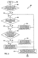
- FIG. 2 a flow diagram 200 which illustrates steps implemented to generate a camera pose transformation matrix is shown.
- the method 200 begins at block 202 in Figure 2 .
- a determination may be made as to whether the relative position and orientation of coordinate systems is known. If the answer to the query posed in block 204 is "yes" in block 206 (the position and orientation of the camera coordinate system relative to the target object is known), then the position and orientation data from the calibration process may be saved for the camera pose as a 4x4 homogeneous transformation matrix in block 222.
- a 5-point calibration method may be used to find both the position and orientation of the camera relative to the target object in block 218. If the outcome of the query which is posed in block 214 is "no" in block 216 (the points of interest and the calibration points do not lie on a planar or nearly planar surface), then a 7-point calibration method may be used to find the position and orientation camera relative to the target object in block 220. The method may then proceed to block 222, in which the position and orientation data from the calibration process may be saved for the camera pose as a 4x4 homogeneous transformation matrix.
- a flow diagram 300 which is a continuation of the flow diagram in Figure 2 , illustrates steps implemented to locate a desired position of interest on a target object is shown.
- the position and orientation data from the calibration process are saved for the camera pose as a 4x4 homogeneous transformation matrix in block 222 of Figure 2
- a camera may be aligned by the pan-tilt unit with a point of interest on a target object and the azimuth and elevation angles of the camera (which defines the direction vector 12 of Figure 1 ) may be determined.
- the azimuth and elevation angles determined in block 222 may be transformed into target object coordinates using the calibration matrix which was saved in block 222 of Figure 2 .
- a query may be made as to whether additional points of interest on the target object are necessary. If additional points of interest on the target object are necessary (block 242), then the method may return to block 224 via block 244. If additional points of interest on the target object are not necessary (block 242), then the method may end at block 246.
- an approximate surface using three known points (such as calibration points) on the target object may be created in block 234.
- the direction vector 12 which is defined by the azimuth and elevation angles is transformed by the calibration matrix save in block 222 and is then intersected with the approximate surface which was created in block 234 to return the target point in object coordinates.
- the result of the calculation made in block 236 may be displayed and the point data may be saved to file in block 238.
- a query may be made as to whether additional points of interest on the target object are necessary.
- the method may return to block 223 via block 244. If the answer to the query posed in block 240 is "no" in block 242 (additional points of interest on the target object are not necessary), then the method may end at block 246.
- the desired point of interest is from entered (e.g. selected from the CAD model, entered from the keyboard, or recalled from storage in another manner) and is used to calculate the direction vector 12 from the position on the target object to the camera in block 250.
- This direction vector is then converted into azimuth and elevation angles in camera coordinates using the inverse of the camera calibration transformation matrix in block 252.
- the pan-tilt unit is then moved to these angles in block 254.
- a query may be made as to whether additional points of interest on the target object are necessary.
- the method may return to block 223 via block 260. If the answer to the query posed in block 256 is "no" in block 258 (additional points of interest on the target object are not necessary), then the method may end at block 262.
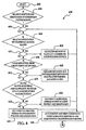
- FIG. 4 a flow diagram 400 which illustrates steps implemented to generate a camera pose transformation matrix according to an alternative illustrative embodiment of the repair and maintenance method is shown.
- the method 400 begins at block 402 in Figure 4 .
- block 404 a determination is made as to whether the relative position and orientation of coordinate systems is known. If the answer to the query in block 404 is known in block 406, then the position and orientation data from the calibration process may be saved as a 4x4 homogeneous transformation matrix in block 426.
- the laser distances and a distance-based method may be used to find both the relative position and orientation of camera relative to the target object in block 418. If the outcome of the query which is posed in block 414 is "no" in block 416 (the laser reflections from the target points on the target object are not acceptable), then a query is made as to whether the calibration points and the points of interest lie on a planar or nearly planar surface.
- a 5-point calibration method may be used to find the position and orientation of the camera relative to the target object in block 424.
- the method may then proceed to block 426, in which the position and orientation data from the calibration process may be saved as a 4x4 homogeneous transformation matrix.
- a 7-point calibration method may be used to find the position and orientation of the camera relative to the target object in block 425.
- the method may then proceed to block 426, in which the position and orientation data from the calibration process may be saved as a 4x4 homogeneous transformation matrix.
- a flow diagram 500 which is a continuation of the flow diagram in Figure 4 , illustrates steps implemented to locate a desired position of interest on a target object is shown.
- the position and orientation data from the calibration process are saved as a 4x4 homogeneous transformation matrix in block 426 of Figure 4 , if the answer to the query posed in block 427 is "new point", then in block 428 a camera may be aligned by the pan-tilt unit with a point of interest on a target object and azimuth and elevation angles of the camera (which defines the direction vector 12) may be determined.
- the azimuth and elevation angles determined in block 428 may be transformed into target object coordinates using the calibration matrix which was saved in block 426 of Figure 4 .
- a determination is made as to whether an accurate three-dimensional model of the target object is available. If the answer to the query posed in block 432 is "yes" in block 230 (an accurate 3-D model of the target object is available), then direction vector 12 defined by the azimuth and elevation angles, is transformed into the coordinate system of the target object by the calibration matrix and is then intersected with the 3-D model of the target object to return the target point in object coordinates in block 436. The result of the calculation made in block 436 may be displayed and the point data may be saved to file in block 442.
- a query may be made as to whether additional points of interest on the target object are necessary. If additional points of interest on the target object are necessary (block 446), then the method may return to block 427 via block 448. If additional points of interest on the target object are not necessary (block 446), then the method may end at block 450.
- the desired point of interest is from entered (e.g. selected from the CAD model, entered from the keyboard, or recalled from storage in another manner) and is used to calculate the direction vector 12 from the position on the target object to the camera in block 451.
- This direction vector is then converted into azimuth and elevation angles in camera coordinates using the inverse of the camera calibration transformation matrix in block 452.
- the pan-tilt unit is then moved to these angles in block 454.
- a query may be made as to whether additional points of interest on the target object are necessary.
- the method may return to block 427 via block 460. If the answer to the query posed in block 456 is "no" in block 458 (additional points of interest on the target object are not necessary), then the method may end at block 462.
- an approximate surface using three known points (such as calibration points) on the target object may be created in block 438.
- the direction vector 12 which is defined by the transformed azimuth and elevation angles, may be transformed by the calibration matrix saved in block 426 and then intersected with the approximate surface which was created in block 438 to return the target point in object coordinates.
- the result of the calculation made in block 440 may be displayed and the point data may be saved to file in block 442.
- a query may be made as to whether additional points of interest on the target object are necessary.
- the method may return to block 428 via block 448. If the answer to the query posed in block 444 is "no" in block 446 (additional points of interest on the target object are not necessary), then the method may end at block 450.
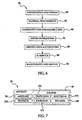
- embodiments of this invention may be used in the context of an aircraft manufacturing and service method 78 as shown in Figure 6 and an aircraft 94 as shown in Figure 7 .
- exemplary method 78 may include specification and design 80 of the aircraft 94 and material procurement 82.
- component and subassembly manufacturing 84 and system integration 86 of the aircraft 94 takes place.
- the aircraft 94 may go through certification and delivery 88 in order to be placed in service 90.
- routine maintenance and service 92 which may also include modification, reconfiguration, refurbishment, and so on).
- Each of the processes of method 78 may be performed or carried out by a system integrator, a third party, and/or an operator (e.g., a customer).
- a system integrator may include without limitation any number of aircraft manufacturers and major-system subcontractors
- a third party may include without limitation any number of vendors, subcontractors, and suppliers
- an operator may be an airline, leasing company, military entity, service organization, and so on.
- the aircraft 94 produced by exemplary method 78 may include an airframe 98 with a plurality of systems 96 and an interior 100.
- high-level systems 96 include one or more of a propulsion system 102, an electrical system 104, a hydraulic system 106, and an environmental system 108. Any number of other systems may be included.
- an aerospace example is shown, the principles of the disclosure may be applied to other industries, such as the automotive, architectural, and ship building industries.
- the apparatus embodied herein may be employed during any one or more of the stages of the production and service method 78.
- components or subassemblies corresponding to production process 84 may be fabricated or manufactured in a manner similar to components or subassemblies produced while the aircraft 94 is in service.
- one or more apparatus embodiments may be utilized during the production stages 84 and 86, for example, by substantially expediting assembly of or reducing the cost of an aircraft 94.
- one or more apparatus embodiments may be utilized while the aircraft 94 is in service, for example and without limitation, to maintenance and service 92.
- One or more apparatus embodiments may be used as part of a real-time airplane health management system.
Landscapes
- Engineering & Computer Science (AREA)
- Physics & Mathematics (AREA)
- General Physics & Mathematics (AREA)
- Remote Sensing (AREA)
- Radar, Positioning & Navigation (AREA)
- Computer Vision & Pattern Recognition (AREA)
- Theoretical Computer Science (AREA)
- Multimedia (AREA)
- Manufacturing & Machinery (AREA)
- Signal Processing (AREA)
- Electromagnetism (AREA)
- Length Measuring Devices By Optical Means (AREA)
- Image Processing (AREA)
Claims (12)
- Lokales Positionsbestimmungssystem (1), umfassend:ein Gestell (4);einen vom Gestell getragenen Schwenk- / Neigemechanismus (3);eine vom Schwenk- / Neigemechanismus getragene Videokamera (2), wobei der Schwenk- / Neigemechanismus angepasst ist, um die Videokamera zu schwenken und zu neigen;einen Rechner (8), der mit der Videokamera und dem Schwenk- / Neigemechanismus kommuniziert;ein Zielobjekt (14), das von der Videokamera anvisiert wird und eine positionell zu vermessende Reparaturstelle sowie ein Zielobjektkoordinatensystem aufweist;wobeider Rechner angepasst ist, um eine Position und Ausrichtung der Videokamera im Zielobjektkoordinatensystem zu bestimmen, und um eine Position der Reparaturstelle im Zielobjektkoordinatensystem zu bestimmen;dadurch gekennzeichnet, dassder Rechner angepasst ist, um auf eine Wartungsdatenbank zuzugreifen;der Rechner angepasst ist, um ein dreidimensionales Modell des Zielobjekts abzurufen und das Zielobjektkoordinatensystem sowie die Reparaturstelle auf dem dreidimensionalen Modell des Zielobjekts anzuzeigen; undder Rechner angepasst ist, um vorherige Reparaturstellen des Zielobjekts auf dem dreidimensionalen Modell des Zielobjekts auf Grundlage der Wartungsdatenbank anzugeben.
- System nach Anspruch 1, wobei
die Videokamera ein Kamerakoordinatensystem aufweist;
der Schwenk- / Neigemechanismus (3) angepasst ist, um die Videokamera (2) in ausgewählten Winkeln bezüglich einer Azimutachse (20) und in einem ausgewählten Rotationswinkel entlang einer Elevationsachse (21) zu bewegen;
der Rechner (8) mit der Videokamera und dem Schwenk- / Neigemechanismus (3) kommuniziert;
die Videokamera angepasst ist, um eine Mehrzahl von Kalibrierungspunkten (15) mit bekanntem Ort auf dem Zielobjekt (14) abzubilden; und
der Rechner (8) angepasst ist, um eine relative Position und Ausrichtung der Videokamera bezüglich des Zielobjekts auf Grundlage der Mehrzahl von Kalibrierungspunkten festzulegen, eine Kameraposenumsetzungsmatrix zum Umsetzen eines Richtungsvektors, der im Kamerakoordinatensystem durch die ausgewählten Winkel der Videokamera bezüglich der Azimutachse und der Elevationsachse festgelegt ist, ins Zielobjektkoordinatensystem auf Grundlage der relativen Position und Ausrichtung zu erzeugen, im Kamerakoordinatensystem festgelegte Positionsvektoren ins Zielobjektkoordinatensystem zu überführen, eine Position und Ausrichtung der Videokamera im Zielobjektkoordinatensystem zu bestimmen, und eine Position der Reparaturstelle im Zielobjektkoordinatensystem zu bestimmen durch Vornehmen von Koordinatensystemumsetzungen unter Verwendung der Kameraposenumsetzungsmatrix. - System nach Anspruch 1 oder 2, wobei eine Lokalisierungssoftware in Firmware auf einem ASIC (einer anwendungsspezifischen integrierten Schaltung) oder einem FPGA (einer feldprogrammierbaren Gatteranordnung) programmiert ist anstelle von Software vom Rechner.
- System nach einem der Ansprüche 1 - 3, das weiterhin zumindest einen auf der Videokamera vorgesehenen Laserpointer (26) umfasst.
- System nach einem der Ansprüche 1 - 4, wobei der Rechner angepasst ist, um digitale Photographien der vorherigen Reparaturen des Zielobjekts mit dem dreidimensionalen Modell des Zielobjekts zu speichern.
- System nach einem der Ansprüche 1 - 5, wobei entweder eine Bildererfassungs- oder eine Anzeigekomponente des Systems einen Fadenkreuzgenerator umfasst.
- Lokales Positionsbestimmungsverfahren, umfassend:Bereitstellen einer Videokamera (2), wobei die Videokamera angepasst ist, um sich zu schwenken und zu neigen;Bereitstellen eines Zielobjekts (14) mit einem Zielobjektkoordinatensystem und einer Reparaturstelle auf dem Zielobjekt;Bestimmen einer Position und Ausrichtung der Videokamera im Zielobjektkoordinatensystem;Visieren der Videokamera auf die Reparaturstelle auf dem Zielobjekt; undBestimmen einer Position der Reparaturstelle im Zielobjektkoordinatensystem;dadurch gekennzeichnet, dass das Verfahren weiterhin umfasst:Zugreifen auf eine Wartungsdatenbank;Bereitstellen eines dreidimensionalen Modells des Zielobjekts, und Anzeigen des Zielobjektkoordinatensystems sowie der Reparaturstelle auf dem dreidimensionalen Modell des Zielobjekts; undAngeben von Reparaturstellen des Zielobjekts auf dem dreidimensionalen Modell des Zielobjekts auf Grundlage der Wartungsdatenbank.
- Verfahren nach Anspruch 7, wobei
die Videokamera (2) ein Kamerakoordinatensystem aufweist und angepasst ist, um in ausgewählten Winkeln bezüglich einer Azimutachse (20) und in einem ausgewählten Rotationswinkel entlang einer Elevationsachse (21) zu bewegen;
das Zielobjekt eine Mehrzahl von Kalibrierungspunkten (15) mit bekanntem Ort aufweist;
wobei das Verfahren weiterhin die Schritte umfasst:Visieren der Videokamera auf die Mehrzahl von Kalibrierungspunkten auf dem Zielobjekt;Festlegen der relativen Position und Ausrichtung der Videokamera bezüglich des Zielobjekts auf Grundlage der Mehrzahl von Kalibrierungspunkten (15);Erzeugen einer Kameraposenumsetzungsmatrix zum Umsetzen eines Richtungsvektors, der im Kamerakoordinatensystem durch die ausgewählten Winkel der Videokamera bezüglich der Azimutachse und der Elevationsachse festgelegt ist, ins Zielobjektkoordinatensystem auf Grundlage der relativen Position und Ausrichtung;Überführen im Kamerakoordinatensystem festgelegter Positionsvektoren ins Zielobjektkoordinatensystem; undBestimmen der Position der Reparaturstelle im Zielobjektkoordinatensystem durch Verwenden der Kameraposenumsetzungsmatrix. - Verfahren nach einem der Ansprüche 7 - 8, wobei der Schritt des Festlegens einer relativen Position und Ausrichtung der Videokamera bezüglich des Zielobjekts das Ausnutzen von zumindest drei der Kalibrierungspunkte auf dem Zielobjekt umfasst, um die Position und Ausrichtung der Videokamera bezüglich des Zielobjekts festzulegen;
bevorzugt das Ausnutzen von fünf der Kalibrierungspunkte, die auf einer gemeinsamen Ebene auf dem Zielobjekt liegen, um die Position und Ausrichtung der Videokamera bezüglich des Zielobjekts festzulegen;
stärker bevorzugt das Ausnutzen von sieben der Kalibrierungspunkte auf dem Zielobjekt, um die Position und Ausrichtung der Videokamera bezüglich des Zielobjekts festzulegen. - Verfahren nach einem der Ansprüche 7 - 9, wobei der Schritt des Festlegens einer relativen Position und Ausrichtung der Videokamera bezüglich des Zielobjekts das Bereitstellen eines Lasers und das Einsetzen einer Messung des Abstands vom Laser zum Zielobjekt umfasst, um einen Abstand von der Videokamera zu den Kalibrierungspunkten auf dem Zielobjekt zu schätzen.
- Verfahren nach einem der Ansprüche 7 - 10, das weiterhin den Schritt des Speicherns digitaler Photographien der vorherigen Reparaturen des Zielobjekts mit dem dreidimensionalen Modell des Zielobjekts umfasst.
- System nach einem der Ansprüche 1 - 6, wobei ein optisches Zielgerät, das ein Teleskop umfasst, anstelle der Videokamera eingesetzt wird.
Applications Claiming Priority (2)
| Application Number | Priority Date | Filing Date | Title |
|---|---|---|---|
| US11/863,755 US8044991B2 (en) | 2007-09-28 | 2007-09-28 | Local positioning system and method |
| PCT/US2008/077178 WO2009045770A2 (en) | 2007-09-28 | 2008-09-22 | Local positioning system and method |
Publications (2)
| Publication Number | Publication Date |
|---|---|
| EP2201532A2 EP2201532A2 (de) | 2010-06-30 |
| EP2201532B1 true EP2201532B1 (de) | 2012-02-29 |
Family
ID=40507749
Family Applications (1)
| Application Number | Title | Priority Date | Filing Date |
|---|---|---|---|
| EP08835068A Active EP2201532B1 (de) | 2007-09-28 | 2008-09-22 | Lokales positionsbestimmungssystem und -verfahren |
Country Status (5)
| Country | Link |
|---|---|
| US (1) | US8044991B2 (de) |
| EP (1) | EP2201532B1 (de) |
| JP (1) | JP5337805B2 (de) |
| AT (1) | ATE547690T1 (de) |
| WO (1) | WO2009045770A2 (de) |
Cited By (5)
| Publication number | Priority date | Publication date | Assignee | Title |
|---|---|---|---|---|
| DE102014018789A1 (de) * | 2014-12-19 | 2016-06-23 | Rheinmetall Air Defence Ag | Verfahren zur Bekämpfung von Militärfahrzeugen |
| US11995228B2 (en) | 2022-01-11 | 2024-05-28 | Rockwell Collins, Inc. | Head tracking system with extended kalman filter combining absolute and relative navigation |
| US12136234B2 (en) | 2022-01-11 | 2024-11-05 | Rockwell Collins, Inc. | Vision-based navigation system incorporating model-based correspondence determination with high-confidence ambiguity identification |
| US12198380B2 (en) | 2022-01-11 | 2025-01-14 | Rockwell Collins, Inc. | Vision-based navigation system incorporating high-confidence error overbounding of multiple optical poses |
| US12347139B2 (en) | 2022-01-11 | 2025-07-01 | Rockwell Collins, Inc. | High-confidence optical head pose correspondence mapping with multiple lower-density markers for high-integrity headtracking on a headworn display (HWD) |
Families Citing this family (87)
| Publication number | Priority date | Publication date | Assignee | Title |
|---|---|---|---|---|
| WO2006024078A1 (en) * | 2004-08-30 | 2006-03-09 | Trace Optic Technologies Pty Ltd | A method and apparatus of camera control |
| US8044991B2 (en) * | 2007-09-28 | 2011-10-25 | The Boeing Company | Local positioning system and method |
| US8265376B2 (en) * | 2008-07-21 | 2012-09-11 | Cognitens Ltd. | Method and system for providing a digital model of an object |
| EP2154650A1 (de) * | 2008-08-12 | 2010-02-17 | IEE INTERNATIONAL ELECTRONICS & ENGINEERING S.A. | 3D-Flugzeit-Kamerasystem und zugehöriges Positions-/Orientierungs-Kalibrationsverfahren |
| US8138938B2 (en) * | 2008-10-28 | 2012-03-20 | The Boeing Company | Hand-held positioning interface for spatial query |
| US8207841B2 (en) * | 2008-10-28 | 2012-06-26 | Ford Global Technologies, Llc | Vehicle information display and method |
| JP5347144B2 (ja) * | 2009-02-03 | 2013-11-20 | リコーイメージング株式会社 | 定点撮影が可能なカメラ |
| US8977528B2 (en) * | 2009-04-27 | 2015-03-10 | The Boeing Company | Bonded rework simulation tool |
| US9108738B1 (en) | 2009-05-19 | 2015-08-18 | The Boeing Company | Apparatus for refueling aircraft |
| US8568545B2 (en) * | 2009-06-16 | 2013-10-29 | The Boeing Company | Automated material removal in composite structures |
| JP4560128B1 (ja) * | 2009-08-13 | 2010-10-13 | 株式会社パスコ | 地図画像統合データベース生成システム及び地図画像統合データベース生成プログラム |
| US8319951B1 (en) | 2009-09-17 | 2012-11-27 | The Boeing Company | Local positioning system |
| US9149929B2 (en) | 2010-05-26 | 2015-10-06 | The Boeing Company | Methods and systems for inspection sensor placement |
| US8983794B1 (en) | 2010-10-04 | 2015-03-17 | The Boeing Company | Methods and systems for non-destructive composite evaluation and repair verification |
| US9182487B2 (en) | 2011-06-22 | 2015-11-10 | The Boeing Company | Advanced remote nondestructive inspection system and process |
| US9804577B1 (en) | 2010-10-04 | 2017-10-31 | The Boeing Company | Remotely operated mobile stand-off measurement and inspection system |
| US8744133B1 (en) | 2010-10-04 | 2014-06-03 | The Boeing Company | Methods and systems for locating visible differences on an object |
| US8899359B1 (en) | 2010-11-05 | 2014-12-02 | The Boeing Company | Locomotion system for robotic snake |
| US8447805B2 (en) | 2011-02-28 | 2013-05-21 | The Boeing Company | Distributed operation of a local positioning system |
| US9250213B1 (en) | 2011-06-14 | 2016-02-02 | The Boeing Company | Ultrasound inspection system for inspecting a test object with non-planar features |
| US8713998B2 (en) | 2011-06-14 | 2014-05-06 | The Boeing Company | Autonomous non-destructive evaluation system for aircraft structures |
| US9082208B2 (en) * | 2011-07-12 | 2015-07-14 | Spirit Aerosystems, Inc. | System and method for locating and displaying aircraft information |
| US8738226B2 (en) | 2011-07-18 | 2014-05-27 | The Boeing Company | Holonomic motion vehicle for travel on non-level surfaces |
| US8874371B2 (en) | 2011-08-09 | 2014-10-28 | The Boeing Company | Beam directed motion control system |
| US10268761B2 (en) | 2011-12-21 | 2019-04-23 | The Boeing Company | Panoptic visualization document collection |
| US9524342B2 (en) | 2011-12-21 | 2016-12-20 | The Boeing Company | Panoptic visualization document navigation |
| US9104760B2 (en) | 2011-12-21 | 2015-08-11 | The Boeing Company | Panoptic visualization document database management |
| US9310317B2 (en) * | 2012-01-25 | 2016-04-12 | The Boeing Company | Automated system and method for tracking and detecting discrepancies on a target object |
| US9495476B2 (en) | 2012-03-23 | 2016-11-15 | The Boeing Company | Panoptic visualization of an illustrated parts catalog |
| CN102706318B (zh) * | 2012-06-05 | 2014-04-02 | 苏州凤凰索卡亚光电科技有限公司 | 可倒挂使用的电子经纬仪 |
| US10354138B2 (en) | 2012-06-18 | 2019-07-16 | Collineo Inc. | Remote visual inspection system and method |
| US9448758B2 (en) * | 2012-07-18 | 2016-09-20 | The Boeing Company | Projecting airplane location specific maintenance history using optical reference points |
| US10268662B2 (en) | 2012-09-10 | 2019-04-23 | The Boeing Company | Panoptic visualization of a document according to the structure thereof |
| US10275428B2 (en) | 2012-09-25 | 2019-04-30 | The Boeing Company | Panoptic visualization document differencing |
| US10824680B2 (en) | 2012-10-02 | 2020-11-03 | The Boeing Company | Panoptic visualization document access control |
| EP2727843B1 (de) | 2012-10-30 | 2020-07-01 | The Boeing Company | Vorrichtung zur automatisierten Wartung von Flugzeugstrukturelementen |
| US9875220B2 (en) | 2012-11-09 | 2018-01-23 | The Boeing Company | Panoptic visualization document printing |
| US20140184750A1 (en) * | 2012-12-31 | 2014-07-03 | Areva Np Inc. | Stereo Vision Encoded Ultrasonic Inspection |
| US9285296B2 (en) * | 2013-01-02 | 2016-03-15 | The Boeing Company | Systems and methods for stand-off inspection of aircraft structures |
| US9414026B2 (en) | 2013-01-25 | 2016-08-09 | The Boeing Company | System and method for automated crack inspection and repair |
| US9734625B2 (en) | 2013-01-28 | 2017-08-15 | The Boeing Company | Panoptic visualization of a three-dimensional representation of a complex system |
| US9665557B2 (en) | 2013-01-28 | 2017-05-30 | The Boeing Company | Panoptic visualization of elements of a complex system using localization of a point on a physical instance of the complex system |
| US9858245B2 (en) | 2013-01-28 | 2018-01-02 | The Boeing Company | Panoptic visualization of elements of a complex system using a model viewer |
| US8887993B2 (en) | 2013-04-23 | 2014-11-18 | The Boeing Company | Barcode access to electronic resources for complex system parts |
| US9098593B2 (en) | 2013-04-23 | 2015-08-04 | The Boeing Company | Barcode access to electronic resources for lifecycle tracking of complex system parts |
| US10162352B2 (en) | 2013-05-13 | 2018-12-25 | The Boeing Company | Remotely operated mobile stand-off measurement and inspection system |
| US9043146B2 (en) * | 2013-06-19 | 2015-05-26 | The Boeing Company | Systems and methods for tracking location of movable target object |
| CN103399319A (zh) * | 2013-07-22 | 2013-11-20 | 山东神戎电子股份有限公司 | 一种适用于视频监控的空间目标定位方法 |
| US10791319B1 (en) | 2013-08-28 | 2020-09-29 | Outward, Inc. | Multi-camera 3D content creation |
| US9488589B2 (en) | 2013-10-29 | 2016-11-08 | The Boeing Company | Mapping damaged regions on objects |
| JP6325834B2 (ja) * | 2014-02-07 | 2018-05-16 | 三菱航空機株式会社 | 整備支援システムおよび整備支援方法 |
| FR3021442B1 (fr) | 2014-05-21 | 2018-01-12 | Airbus Group Sas | Procede de traitement d'informations locales |
| US9841870B2 (en) | 2014-08-21 | 2017-12-12 | The Boeing Company | Integrated visualization and analysis of a complex system |
| US9489597B2 (en) | 2014-08-21 | 2016-11-08 | The Boeing Company | Visualization and analysis of a topical element of a complex system |
| US10191997B2 (en) | 2014-08-21 | 2019-01-29 | The Boeing Company | Visualization and diagnostic analysis of interested elements of a complex system |
| US9575004B2 (en) | 2014-11-17 | 2017-02-21 | The Boeing Company | Automated low cost method for illuminating, evaluating, and qualifying surfaces and surface coatings |
| US9924103B2 (en) * | 2015-04-09 | 2018-03-20 | The Boeing Company | Automated local positioning system calibration using optically readable markers |
| US9892558B2 (en) | 2016-02-19 | 2018-02-13 | The Boeing Company | Methods for localization using geotagged photographs and three-dimensional visualization |
| US10607409B2 (en) | 2016-07-19 | 2020-03-31 | The Boeing Company | Synthetic geotagging for computer-generated images |
| US20180120196A1 (en) | 2016-10-31 | 2018-05-03 | The Boeing Company | Method and system for non-destructive testing using an unmanned aerial vehicle |
| CN106933254B (zh) * | 2017-03-03 | 2020-05-19 | 鞍山天源科技有限公司 | 一种无框架球型云台装置 |
| DE102017109039A1 (de) * | 2017-04-27 | 2018-10-31 | Sick Ag | Verfahren zur Kalibrierung einer Kamera und eines Laserscanners |
| US10627475B2 (en) | 2017-05-05 | 2020-04-21 | The Boeing Company | Pose estimation using radio frequency identification (RFID) tags |
| US10633066B2 (en) | 2018-03-27 | 2020-04-28 | The Boeing Company | Apparatus and methods for measuring positions of points on submerged surfaces |
| US11238675B2 (en) * | 2018-04-04 | 2022-02-01 | The Boeing Company | Mobile visual-inspection system |
| US10800550B2 (en) | 2018-06-21 | 2020-10-13 | The Boeing Company | Positioning enhancements to localization process for three-dimensional visualization |
| US12194620B2 (en) | 2018-10-15 | 2025-01-14 | Oliver Crisipin Robotics Limited | Selectively flexible extension tool |
| US11079760B2 (en) | 2018-11-28 | 2021-08-03 | The Boeing Company | Methods for maintaining difficult-to-access structures using unmanned aerial vehicles |
| US11385204B2 (en) | 2018-12-11 | 2022-07-12 | The Boeing Company | Fan-propelled surface-adhering apparatus for automated maintenance operations |
| US11702955B2 (en) | 2019-01-14 | 2023-07-18 | General Electric Company | Component repair system and method |
| US11275391B2 (en) | 2019-05-13 | 2022-03-15 | The Boeing Company | In-service maintenance process using unmanned aerial vehicles |
| CN110675390A (zh) * | 2019-09-27 | 2020-01-10 | 广东博智林机器人有限公司 | 一种建筑质量全局检测方法及装置 |
| US12405187B2 (en) | 2019-10-04 | 2025-09-02 | General Electric Company | Insertion apparatus for use with rotary machines |
| US11630459B2 (en) | 2020-01-29 | 2023-04-18 | The Boeing Company | Repair of structures using unmanned aerial vehicles |
| US11529777B2 (en) | 2020-02-05 | 2022-12-20 | The Boeing Company | Hot bond repair of structures using unmanned aerial vehicles |
| US11891174B2 (en) | 2020-02-05 | 2024-02-06 | The Boeing Company | Repair of structures using unmanned aerial vehicles |
| US12169126B2 (en) * | 2020-04-06 | 2024-12-17 | University Of Iowa Research Foundation | Camera-based liquid stage measurement |
| US11555693B2 (en) | 2020-05-12 | 2023-01-17 | The Boeing Company | Measurement of surface profiles using unmanned aerial vehicles |
| CN111504613B (zh) * | 2020-05-13 | 2022-07-29 | 飒铂智能科技有限责任公司 | 一种激光器光轴标定方法及系统 |
| US12091981B2 (en) | 2020-06-11 | 2024-09-17 | General Electric Company | Insertion tool and method |
| US11745872B2 (en) | 2020-06-19 | 2023-09-05 | The Boeing Company | Methods for marking surfaces using unmanned aerial vehicles |
| US12416800B2 (en) | 2021-01-08 | 2025-09-16 | General Electric Company | Insertion tool |
| US12504616B2 (en) | 2021-01-08 | 2025-12-23 | General Electric Company | Insertion tool |
| JP7582460B2 (ja) * | 2021-05-17 | 2024-11-13 | 日本電気株式会社 | 撮影条件決定方法、撮影条件決定システム、撮影条件決定装置、及びプログラム |
| CN113506340B (zh) * | 2021-06-15 | 2024-08-20 | 浙江大华技术股份有限公司 | 一种云台位姿预测的方法、设备和计算机可读存储介质 |
| US12026912B2 (en) * | 2021-09-13 | 2024-07-02 | Wen Li | Apparatus and methodology for aiming point and aiming device 6DOF detection using image registration |
| CN115439531A (zh) * | 2022-06-21 | 2022-12-06 | 亮风台(上海)信息科技有限公司 | 一种获取目标对象的目标空间位置信息的方法与设备 |
Citations (1)
| Publication number | Priority date | Publication date | Assignee | Title |
|---|---|---|---|---|
| JP2003271993A (ja) * | 2002-03-18 | 2003-09-26 | Hitachi Ltd | モニタ画像処理方法及び画像モニタシステム並びに保全作業システム |
Family Cites Families (18)
| Publication number | Priority date | Publication date | Assignee | Title |
|---|---|---|---|---|
| US5590268A (en) * | 1993-03-31 | 1996-12-31 | Kabushiki Kaisha Toshiba | System and method for evaluating a workspace represented by a three-dimensional model |
| US5590900A (en) * | 1995-07-21 | 1997-01-07 | Avibank Mfg., Inc. | Air bag mounting system |
| US6697067B1 (en) * | 1999-09-28 | 2004-02-24 | Cedera Software Corp. | Method and system for storing information regarding a selected view of a three dimensional image generated from a multi-frame object |
| EP1102211A3 (de) * | 1999-11-19 | 2006-09-13 | Matsushita Electric Industrial Co., Ltd. | Bildprozessor, Verfahren zur Bereitstellung von Bildverarbeitungsdiensten und Bestellungsverarbeitungsverfahren |
| AU2001293081A1 (en) | 2000-09-29 | 2002-04-08 | C.I. System Ltd. | Method and apparatus for the precise alignment of a weapon relative to a sight |
| JP4200763B2 (ja) * | 2003-01-08 | 2008-12-24 | 株式会社ニコン | 画像測定機および画像測定方法 |
| JP4227037B2 (ja) * | 2004-02-25 | 2009-02-18 | 株式会社国際電気通信基礎技術研究所 | 撮像システム及び校正方法 |
| JP4135934B2 (ja) * | 2004-03-30 | 2008-08-20 | 株式会社ナック映像センター | 電子機器 |
| EP1831657B1 (de) * | 2004-12-03 | 2018-12-05 | Fluke Corporation | Verfahren für eine kombinierte bildkamera für sichtbares licht und ir |
| US7657117B2 (en) | 2004-12-20 | 2010-02-02 | Palo Alto Research Center Incorporated | Method and apparatus for calibrating a camera-based whiteboard scanner |
| CN101084498A (zh) * | 2004-12-31 | 2007-12-05 | 富士通株式会社 | 三维模型的检索方法和装置 |
| JP4726191B2 (ja) * | 2005-02-04 | 2011-07-20 | キヤノン株式会社 | 位置姿勢補正装置、位置姿勢補正方法、そのプログラムおよび記憶媒体 |
| JP4599515B2 (ja) * | 2005-05-27 | 2010-12-15 | コニカミノルタセンシング株式会社 | 3次元形状データの位置合わせ方法および装置 |
| DE102005025470B4 (de) * | 2005-06-02 | 2007-12-20 | Metaio Gmbh | Verfahren und System zur Ermittlung der Position und Orientierung einer Kamera relativ zu einem realen Objekt |
| JP4769079B2 (ja) * | 2005-12-15 | 2011-09-07 | 日本放送協会 | カメラ情報解析装置 |
| US8044991B2 (en) | 2007-09-28 | 2011-10-25 | The Boeing Company | Local positioning system and method |
| CN101918989B (zh) * | 2007-12-07 | 2013-02-13 | 常州环视高科电子科技有限公司 | 带有对象跟踪和检索的视频监控系统 |
| JP4760892B2 (ja) * | 2008-10-10 | 2011-08-31 | ソニー株式会社 | 表示制御装置、表示制御方法及びプログラム |
-
2007
- 2007-09-28 US US11/863,755 patent/US8044991B2/en active Active
-
2008
- 2008-09-22 EP EP08835068A patent/EP2201532B1/de active Active
- 2008-09-22 JP JP2010527062A patent/JP5337805B2/ja active Active
- 2008-09-22 WO PCT/US2008/077178 patent/WO2009045770A2/en not_active Ceased
- 2008-09-22 AT AT08835068T patent/ATE547690T1/de active
Patent Citations (1)
| Publication number | Priority date | Publication date | Assignee | Title |
|---|---|---|---|---|
| JP2003271993A (ja) * | 2002-03-18 | 2003-09-26 | Hitachi Ltd | モニタ画像処理方法及び画像モニタシステム並びに保全作業システム |
Cited By (5)
| Publication number | Priority date | Publication date | Assignee | Title |
|---|---|---|---|---|
| DE102014018789A1 (de) * | 2014-12-19 | 2016-06-23 | Rheinmetall Air Defence Ag | Verfahren zur Bekämpfung von Militärfahrzeugen |
| US11995228B2 (en) | 2022-01-11 | 2024-05-28 | Rockwell Collins, Inc. | Head tracking system with extended kalman filter combining absolute and relative navigation |
| US12136234B2 (en) | 2022-01-11 | 2024-11-05 | Rockwell Collins, Inc. | Vision-based navigation system incorporating model-based correspondence determination with high-confidence ambiguity identification |
| US12198380B2 (en) | 2022-01-11 | 2025-01-14 | Rockwell Collins, Inc. | Vision-based navigation system incorporating high-confidence error overbounding of multiple optical poses |
| US12347139B2 (en) | 2022-01-11 | 2025-07-01 | Rockwell Collins, Inc. | High-confidence optical head pose correspondence mapping with multiple lower-density markers for high-integrity headtracking on a headworn display (HWD) |
Also Published As
| Publication number | Publication date |
|---|---|
| EP2201532A2 (de) | 2010-06-30 |
| JP5337805B2 (ja) | 2013-11-06 |
| US20090086014A1 (en) | 2009-04-02 |
| ATE547690T1 (de) | 2012-03-15 |
| WO2009045770A3 (en) | 2010-04-01 |
| JP2010540933A (ja) | 2010-12-24 |
| US8044991B2 (en) | 2011-10-25 |
| WO2009045770A2 (en) | 2009-04-09 |
Similar Documents
| Publication | Publication Date | Title |
|---|---|---|
| EP2201532B1 (de) | Lokales positionsbestimmungssystem und -verfahren | |
| US7859655B2 (en) | Method involving a pointing instrument and a target object | |
| US10585167B2 (en) | Relative object localization process for local positioning system | |
| US9804577B1 (en) | Remotely operated mobile stand-off measurement and inspection system | |
| US7145647B2 (en) | Measurement of spatial coordinates | |
| US20190079522A1 (en) | Unmanned aerial vehicle having a projector and being tracked by a laser tracker | |
| US9007601B2 (en) | Automatic measurement of dimensional data with a laser tracker | |
| US8744133B1 (en) | Methods and systems for locating visible differences on an object | |
| US20170054954A1 (en) | System and method for visually displaying information on real objects | |
| US20140160115A1 (en) | System And Method For Visually Displaying Information On Real Objects | |
| US20180209156A1 (en) | Construction management system and method | |
| US20140132729A1 (en) | Method and apparatus for camera-based 3d flaw tracking system | |
| US10162352B2 (en) | Remotely operated mobile stand-off measurement and inspection system | |
| Summan et al. | Spatial calibration of large volume photogrammetry based metrology systems | |
| EP2350562A1 (de) | Hand-positionierungsschnittstelle für räumliche abfrage | |
| GB2506239A (en) | Projecting maintenance history using optical reference points | |
| CN105987683A (zh) | 一种基于高反光红外标识的视觉定位系统及方法 | |
| JP2010078466A (ja) | マーカ自動登録方法及びシステム | |
| CN108132029A (zh) | 一种卫星天线展开系统装配的精测方法及装置 | |
| JPH09311021A (ja) | 光波測距儀を用いた3次元形状測定方法 | |
| Peng et al. | A measuring method for large antenna assembly using laser and vision guiding technology | |
| El-Hakim et al. | A mobile system for indoors 3-D mapping and positioning | |
| EP3943979A1 (de) | Lokalisierung einer innenraumvorrichtung | |
| Han et al. | Multi-point measurement using DIC based on UAV platform | |
| Scherer | a Circleless" 2D/3D Total STATION": a Low Cost Instrument for Surveying, Recording Point Clouds, Documentation, Image Acquisition and Visualisation |
Legal Events
| Date | Code | Title | Description |
|---|---|---|---|
| PUAI | Public reference made under article 153(3) epc to a published international application that has entered the european phase |
Free format text: ORIGINAL CODE: 0009012 |
|
| 17P | Request for examination filed |
Effective date: 20100331 |
|
| AK | Designated contracting states |
Kind code of ref document: A2 Designated state(s): AT BE BG CH CY CZ DE DK EE ES FI FR GB GR HR HU IE IS IT LI LT LU LV MC MT NL NO PL PT RO SE SI SK TR |
|
| AX | Request for extension of the european patent |
Extension state: AL BA MK RS |
|
| 17Q | First examination report despatched |
Effective date: 20101022 |
|
| DAX | Request for extension of the european patent (deleted) | ||
| REG | Reference to a national code |
Ref country code: DE Ref legal event code: R079 Ref document number: 602008013825 Country of ref document: DE Free format text: PREVIOUS MAIN CLASS: G06T0017000000 Ipc: G01C0011000000 |
|
| GRAP | Despatch of communication of intention to grant a patent |
Free format text: ORIGINAL CODE: EPIDOSNIGR1 |
|
| RIC1 | Information provided on ipc code assigned before grant |
Ipc: H04N 7/18 20060101ALI20111025BHEP Ipc: H04N 5/232 20060101ALI20111025BHEP Ipc: G01S 17/06 20060101ALI20111025BHEP Ipc: G06T 7/00 20060101ALI20111025BHEP Ipc: G01C 25/00 20060101ALI20111025BHEP Ipc: G01C 15/00 20060101ALI20111025BHEP Ipc: G01S 5/16 20060101ALI20111025BHEP Ipc: G01C 11/00 20060101AFI20111025BHEP Ipc: G01C 1/02 20060101ALI20111025BHEP |
|
| GRAS | Grant fee paid |
Free format text: ORIGINAL CODE: EPIDOSNIGR3 |
|
| GRAA | (expected) grant |
Free format text: ORIGINAL CODE: 0009210 |
|
| AK | Designated contracting states |
Kind code of ref document: B1 Designated state(s): AT BE BG CH CY CZ DE DK EE ES FI FR GB GR HR HU IE IS IT LI LT LU LV MC MT NL NO PL PT RO SE SI SK TR |
|
| REG | Reference to a national code |
Ref country code: GB Ref legal event code: FG4D Ref country code: CH Ref legal event code: EP |
|
| REG | Reference to a national code |
Ref country code: AT Ref legal event code: REF Ref document number: 547690 Country of ref document: AT Kind code of ref document: T Effective date: 20120315 |
|
| REG | Reference to a national code |
Ref country code: IE Ref legal event code: FG4D |
|
| REG | Reference to a national code |
Ref country code: DE Ref legal event code: R096 Ref document number: 602008013825 Country of ref document: DE Effective date: 20120426 |
|
| REG | Reference to a national code |
Ref country code: NL Ref legal event code: VDEP Effective date: 20120229 |
|
| LTIE | Lt: invalidation of european patent or patent extension |
Effective date: 20120229 |
|
| PG25 | Lapsed in a contracting state [announced via postgrant information from national office to epo] |
Ref country code: IS Free format text: LAPSE BECAUSE OF FAILURE TO SUBMIT A TRANSLATION OF THE DESCRIPTION OR TO PAY THE FEE WITHIN THE PRESCRIBED TIME-LIMIT Effective date: 20120629 Ref country code: NL Free format text: LAPSE BECAUSE OF FAILURE TO SUBMIT A TRANSLATION OF THE DESCRIPTION OR TO PAY THE FEE WITHIN THE PRESCRIBED TIME-LIMIT Effective date: 20120229 Ref country code: NO Free format text: LAPSE BECAUSE OF FAILURE TO SUBMIT A TRANSLATION OF THE DESCRIPTION OR TO PAY THE FEE WITHIN THE PRESCRIBED TIME-LIMIT Effective date: 20120529 Ref country code: HR Free format text: LAPSE BECAUSE OF FAILURE TO SUBMIT A TRANSLATION OF THE DESCRIPTION OR TO PAY THE FEE WITHIN THE PRESCRIBED TIME-LIMIT Effective date: 20120229 Ref country code: LT Free format text: LAPSE BECAUSE OF FAILURE TO SUBMIT A TRANSLATION OF THE DESCRIPTION OR TO PAY THE FEE WITHIN THE PRESCRIBED TIME-LIMIT Effective date: 20120229 |
|
| PG25 | Lapsed in a contracting state [announced via postgrant information from national office to epo] |
Ref country code: GR Free format text: LAPSE BECAUSE OF FAILURE TO SUBMIT A TRANSLATION OF THE DESCRIPTION OR TO PAY THE FEE WITHIN THE PRESCRIBED TIME-LIMIT Effective date: 20120530 Ref country code: PT Free format text: LAPSE BECAUSE OF FAILURE TO SUBMIT A TRANSLATION OF THE DESCRIPTION OR TO PAY THE FEE WITHIN THE PRESCRIBED TIME-LIMIT Effective date: 20120629 Ref country code: LV Free format text: LAPSE BECAUSE OF FAILURE TO SUBMIT A TRANSLATION OF THE DESCRIPTION OR TO PAY THE FEE WITHIN THE PRESCRIBED TIME-LIMIT Effective date: 20120229 Ref country code: BE Free format text: LAPSE BECAUSE OF FAILURE TO SUBMIT A TRANSLATION OF THE DESCRIPTION OR TO PAY THE FEE WITHIN THE PRESCRIBED TIME-LIMIT Effective date: 20120229 Ref country code: FI Free format text: LAPSE BECAUSE OF FAILURE TO SUBMIT A TRANSLATION OF THE DESCRIPTION OR TO PAY THE FEE WITHIN THE PRESCRIBED TIME-LIMIT Effective date: 20120229 |
|
| REG | Reference to a national code |
Ref country code: AT Ref legal event code: MK05 Ref document number: 547690 Country of ref document: AT Kind code of ref document: T Effective date: 20120229 |
|
| PG25 | Lapsed in a contracting state [announced via postgrant information from national office to epo] |
Ref country code: CY Free format text: LAPSE BECAUSE OF FAILURE TO SUBMIT A TRANSLATION OF THE DESCRIPTION OR TO PAY THE FEE WITHIN THE PRESCRIBED TIME-LIMIT Effective date: 20120229 |
|
| PG25 | Lapsed in a contracting state [announced via postgrant information from national office to epo] |
Ref country code: SE Free format text: LAPSE BECAUSE OF FAILURE TO SUBMIT A TRANSLATION OF THE DESCRIPTION OR TO PAY THE FEE WITHIN THE PRESCRIBED TIME-LIMIT Effective date: 20120229 Ref country code: CZ Free format text: LAPSE BECAUSE OF FAILURE TO SUBMIT A TRANSLATION OF THE DESCRIPTION OR TO PAY THE FEE WITHIN THE PRESCRIBED TIME-LIMIT Effective date: 20120229 Ref country code: EE Free format text: LAPSE BECAUSE OF FAILURE TO SUBMIT A TRANSLATION OF THE DESCRIPTION OR TO PAY THE FEE WITHIN THE PRESCRIBED TIME-LIMIT Effective date: 20120229 Ref country code: DK Free format text: LAPSE BECAUSE OF FAILURE TO SUBMIT A TRANSLATION OF THE DESCRIPTION OR TO PAY THE FEE WITHIN THE PRESCRIBED TIME-LIMIT Effective date: 20120229 Ref country code: RO Free format text: LAPSE BECAUSE OF FAILURE TO SUBMIT A TRANSLATION OF THE DESCRIPTION OR TO PAY THE FEE WITHIN THE PRESCRIBED TIME-LIMIT Effective date: 20120229 Ref country code: PL Free format text: LAPSE BECAUSE OF FAILURE TO SUBMIT A TRANSLATION OF THE DESCRIPTION OR TO PAY THE FEE WITHIN THE PRESCRIBED TIME-LIMIT Effective date: 20120229 Ref country code: SI Free format text: LAPSE BECAUSE OF FAILURE TO SUBMIT A TRANSLATION OF THE DESCRIPTION OR TO PAY THE FEE WITHIN THE PRESCRIBED TIME-LIMIT Effective date: 20120229 |
|
| PG25 | Lapsed in a contracting state [announced via postgrant information from national office to epo] |
Ref country code: SK Free format text: LAPSE BECAUSE OF FAILURE TO SUBMIT A TRANSLATION OF THE DESCRIPTION OR TO PAY THE FEE WITHIN THE PRESCRIBED TIME-LIMIT Effective date: 20120229 Ref country code: IT Free format text: LAPSE BECAUSE OF FAILURE TO SUBMIT A TRANSLATION OF THE DESCRIPTION OR TO PAY THE FEE WITHIN THE PRESCRIBED TIME-LIMIT Effective date: 20120229 |
|
| PLBE | No opposition filed within time limit |
Free format text: ORIGINAL CODE: 0009261 |
|
| STAA | Information on the status of an ep patent application or granted ep patent |
Free format text: STATUS: NO OPPOSITION FILED WITHIN TIME LIMIT |
|
| PG25 | Lapsed in a contracting state [announced via postgrant information from national office to epo] |
Ref country code: AT Free format text: LAPSE BECAUSE OF FAILURE TO SUBMIT A TRANSLATION OF THE DESCRIPTION OR TO PAY THE FEE WITHIN THE PRESCRIBED TIME-LIMIT Effective date: 20120229 |
|
| 26N | No opposition filed |
Effective date: 20121130 |
|
| REG | Reference to a national code |
Ref country code: DE Ref legal event code: R097 Ref document number: 602008013825 Country of ref document: DE Effective date: 20121130 |
|
| PG25 | Lapsed in a contracting state [announced via postgrant information from national office to epo] |
Ref country code: MC Free format text: LAPSE BECAUSE OF NON-PAYMENT OF DUE FEES Effective date: 20120930 Ref country code: ES Free format text: LAPSE BECAUSE OF FAILURE TO SUBMIT A TRANSLATION OF THE DESCRIPTION OR TO PAY THE FEE WITHIN THE PRESCRIBED TIME-LIMIT Effective date: 20120609 |
|
| REG | Reference to a national code |
Ref country code: CH Ref legal event code: PL |
|
| REG | Reference to a national code |
Ref country code: IE Ref legal event code: MM4A |
|
| PG25 | Lapsed in a contracting state [announced via postgrant information from national office to epo] |
Ref country code: BG Free format text: LAPSE BECAUSE OF FAILURE TO SUBMIT A TRANSLATION OF THE DESCRIPTION OR TO PAY THE FEE WITHIN THE PRESCRIBED TIME-LIMIT Effective date: 20120529 Ref country code: CH Free format text: LAPSE BECAUSE OF NON-PAYMENT OF DUE FEES Effective date: 20120930 Ref country code: LI Free format text: LAPSE BECAUSE OF NON-PAYMENT OF DUE FEES Effective date: 20120930 Ref country code: IE Free format text: LAPSE BECAUSE OF NON-PAYMENT OF DUE FEES Effective date: 20120922 |
|
| PG25 | Lapsed in a contracting state [announced via postgrant information from national office to epo] |
Ref country code: MT Free format text: LAPSE BECAUSE OF FAILURE TO SUBMIT A TRANSLATION OF THE DESCRIPTION OR TO PAY THE FEE WITHIN THE PRESCRIBED TIME-LIMIT Effective date: 20120229 |
|
| PG25 | Lapsed in a contracting state [announced via postgrant information from national office to epo] |
Ref country code: TR Free format text: LAPSE BECAUSE OF FAILURE TO SUBMIT A TRANSLATION OF THE DESCRIPTION OR TO PAY THE FEE WITHIN THE PRESCRIBED TIME-LIMIT Effective date: 20120229 |
|
| PG25 | Lapsed in a contracting state [announced via postgrant information from national office to epo] |
Ref country code: LU Free format text: LAPSE BECAUSE OF NON-PAYMENT OF DUE FEES Effective date: 20120922 |
|
| PG25 | Lapsed in a contracting state [announced via postgrant information from national office to epo] |
Ref country code: HU Free format text: LAPSE BECAUSE OF FAILURE TO SUBMIT A TRANSLATION OF THE DESCRIPTION OR TO PAY THE FEE WITHIN THE PRESCRIBED TIME-LIMIT Effective date: 20080922 |
|
| REG | Reference to a national code |
Ref country code: FR Ref legal event code: PLFP Year of fee payment: 9 |
|
| REG | Reference to a national code |
Ref country code: FR Ref legal event code: PLFP Year of fee payment: 10 |
|
| REG | Reference to a national code |
Ref country code: FR Ref legal event code: PLFP Year of fee payment: 11 |
|
| P01 | Opt-out of the competence of the unified patent court (upc) registered |
Effective date: 20230516 |
|
| PGFP | Annual fee paid to national office [announced via postgrant information from national office to epo] |
Ref country code: DE Payment date: 20250929 Year of fee payment: 18 |
|
| PGFP | Annual fee paid to national office [announced via postgrant information from national office to epo] |
Ref country code: GB Payment date: 20250929 Year of fee payment: 18 |
|
| PGFP | Annual fee paid to national office [announced via postgrant information from national office to epo] |
Ref country code: FR Payment date: 20250925 Year of fee payment: 18 |