EP2201299B1 - Stützring für hitzeschildelemente eines flammenrohrs und eine brennkammeranordnung mit einem derartigen stützring - Google Patents
Stützring für hitzeschildelemente eines flammenrohrs und eine brennkammeranordnung mit einem derartigen stützring Download PDFInfo
- Publication number
- EP2201299B1 EP2201299B1 EP08842468A EP08842468A EP2201299B1 EP 2201299 B1 EP2201299 B1 EP 2201299B1 EP 08842468 A EP08842468 A EP 08842468A EP 08842468 A EP08842468 A EP 08842468A EP 2201299 B1 EP2201299 B1 EP 2201299B1
- Authority
- EP
- European Patent Office
- Prior art keywords
- support ring
- flame tube
- groove
- combustion chamber
- groove wall
- Prior art date
- Legal status (The legal status is an assumption and is not a legal conclusion. Google has not performed a legal analysis and makes no representation as to the accuracy of the status listed.)
- Active
Links
Images

Classifications
-
- F—MECHANICAL ENGINEERING; LIGHTING; HEATING; WEAPONS; BLASTING
- F23—COMBUSTION APPARATUS; COMBUSTION PROCESSES
- F23R—GENERATING COMBUSTION PRODUCTS OF HIGH PRESSURE OR HIGH VELOCITY, e.g. GAS-TURBINE COMBUSTION CHAMBERS
- F23R3/00—Continuous combustion chambers using liquid or gaseous fuel
- F23R3/007—Continuous combustion chambers using liquid or gaseous fuel constructed mainly of ceramic components
-
- F—MECHANICAL ENGINEERING; LIGHTING; HEATING; WEAPONS; BLASTING
- F23—COMBUSTION APPARATUS; COMBUSTION PROCESSES
- F23R—GENERATING COMBUSTION PRODUCTS OF HIGH PRESSURE OR HIGH VELOCITY, e.g. GAS-TURBINE COMBUSTION CHAMBERS
- F23R3/00—Continuous combustion chambers using liquid or gaseous fuel
- F23R3/42—Continuous combustion chambers using liquid or gaseous fuel characterised by the arrangement or form of the flame tubes or combustion chambers
- F23R3/60—Support structures; Attaching or mounting means
-
- F—MECHANICAL ENGINEERING; LIGHTING; HEATING; WEAPONS; BLASTING
- F23—COMBUSTION APPARATUS; COMBUSTION PROCESSES
- F23M—CASINGS, LININGS, WALLS OR DOORS SPECIALLY ADAPTED FOR COMBUSTION CHAMBERS, e.g. FIREBRIDGES; DEVICES FOR DEFLECTING AIR, FLAMES OR COMBUSTION PRODUCTS IN COMBUSTION CHAMBERS; SAFETY ARRANGEMENTS SPECIALLY ADAPTED FOR COMBUSTION APPARATUS; DETAILS OF COMBUSTION CHAMBERS, NOT OTHERWISE PROVIDED FOR
- F23M2900/00—Special features of, or arrangements for combustion chambers
- F23M2900/05002—Means for accommodate thermal expansion of the wall liner
-
- F—MECHANICAL ENGINEERING; LIGHTING; HEATING; WEAPONS; BLASTING
- F23—COMBUSTION APPARATUS; COMBUSTION PROCESSES
- F23R—GENERATING COMBUSTION PRODUCTS OF HIGH PRESSURE OR HIGH VELOCITY, e.g. GAS-TURBINE COMBUSTION CHAMBERS
- F23R2900/00—Special features of, or arrangements for continuous combustion chambers; Combustion processes therefor
- F23R2900/03041—Effusion cooled combustion chamber walls or domes
Definitions
- the present invention relates to a support ring for heat shield elements of a flame tube, in particular a flame tube of a gas turbine.
- the invention relates to a combustion chamber arrangement with a flame tube and a mixing housing, as it finds particular use in gas turbines.
- Support rings for heat shield elements may have a groove extending on its outer side, which serves as a cooling air passage.
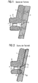
- a section of a support ring according to the prior art is in FIG. 1 illustrated, wherein the support ring is received by the batt ring of a mixing housing.
- the figure shows a section of the support ring 1 and a section of a peg 3 of a mixing housing in a schematic cross-sectional view.
- the support ring has a reinforced portion 5, which in turn is provided with an inner groove 7 and an outer groove 9, both of which extend over the full circumference of the support ring.
- the outer groove 9 and the inner groove 7 are fluidly connected to each other via a number of radial through holes 11.
- the outer groove 9 forms a fresh air supply for cooling the support ring 1.
- the fresh air is then passed through the holes 11 into the combustion chamber interior.
- the reinforced area 5 also forms a flange-like projection projecting toward the interior of the combustion chamber, which forms a support for heat shield elements.
- the object of the present invention is to provide an advantageous support ring and an advantageous combustion chamber arrangement, which in particular make it possible to extend the maintenance intervals for the transition between the flame tube and the mixing housing.
- a flame tube in particular a gas turbine flame tube
- at least one groove is present. This has a relation to the radial direction of the support ring obliquely extending groove wall. Suitable angles between the surface normal of the oblique groove wall to the radial direction of the support ring are in particular in the range between 30 ° and 60 °.
- the oblique groove wall leads when grinding the Zinnenkranzes a mixing housing in the support ring that forms a wedge-shaped projection in the pinnacles. This has one of the oblique groove wall corresponding wedge surface. If, when switching off the gas turbine due to the different thermal expansion behavior of mixing housing and support ring in the axial direction of the support ring acting forces occur, the slope leads to acting in the radial direction of the support ring forces are generated which separate the pinnacles from the support ring. As a result, in particular the tearing off of pinnacles due to an excessive force in the axial direction of the support ring is avoided.
- passage openings may be located in the region of the groove which extend from the outside of the support ring to its inner side and serve as cooling air openings for cooling the support ring and for removing cooling air introduced through the groove.
- the groove wall opposite the oblique groove wall may have a non-planar geometry. In particular, it may form a curved surface in the axial direction of the support ring.
- a wear-resistant layer hard-facing, wear-resistant layer
- a combustion chamber arrangement according to the invention has a flame tube and a mixing housing. It can be used in particular in gas turbines.
- the flame tube has an output end with a support ring for heat shield elements, in particular for ceramic heat shield elements.
- the mixing housing has an edge with protruding pinnacles, wherein the pinnacles form a receiving portion for receiving the support ring.
- the Support ring designed as a support ring according to the invention.
- the armor of the pinnacles can be harder than the armor of the support ring.
- the armor can also be the same, or the armor of the support ring may be harder than the armor of the battlements.
- the armor of the merlons is harder than that of the support ring, since a mending and replacing the support ring in comparison to a repair or replacement of battlements represents less effort.
- a demolition of battlements with the same armor is more likely than damage to the support ring and has more critical consequences for the gas turbine.
- a combustion chamber arrangement according to the invention which has a support ring according to the invention for heat shield elements, also called a stone support ring, will be described below with reference to FIGS FIGS. 3 to 7 described.
- the present embodiment shows a combustion chamber arrangement in which the flame tube is arranged vertically, ie, the axial direction of the flame tube extends in the vertical direction.
- the radial directions of the flame tube represent horizontal directions. The hot gas flowing out of the flame tube in the vertical direction is deflected by the mixing housing in a horizontal flow direction.
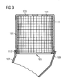
- FIG. 3 shows the combustion chamber assembly, which has a flame tube 101 with a burner end 103, on which the burner (not shown) are arranged, and an outlet end 105, from which occur in the combustion chamber resulting hot gases occur, in a sectional view.
- the flame tube 101 is inserted with its outlet end 105 into a receptacle 109 of a mixing housing 107.
- the mixing housing passes the hot gases leaving the flame tube 101 to the turbine (not shown).
- the interior of the flame tube 101 is provided with ceramic heat shield elements, also called heat shield stones, to protect the combustion chamber wall from the corrosive hot gas.
- the heat shield stones 111 holding stone support ring 113 is arranged, of which a substantial part in the receptacle 109 of the mixing housing 107 is located.
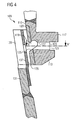
- the receiving portion 109 and the stone support ring 113 are in FIG. 4 partially enlarged.
- the stone support ring 113 has an outer side 115 and an inner side 117. Both in the outside 115, and in the inside 117 grooves 119, 121 are present, which extend over the entire circumference of the stone support ring 113.
- the outside of the stone support ring 113 is also provided with an abrasion-reducing armor 129.
- At regular intervals distributed around the circumference of the stone support ring 113 through holes 123 are present, which connect the groove 119 in the outer side 117 (hereinafter called outer groove 119) with the formed in the inner side 117 groove 121 (hereinafter referred to as inner groove 121) fluidly connect.
- the outer groove 119 serves as a cooling air passage, which allows the distribution of cooling air around the stone support ring 113 around.
- the cooling air can then pass from the outer groove 119 through the through holes 123 in the inner groove 121 and from there into the combustion chamber interior.
- the outer groove 117 and the inner groove 121 are disposed in a flange-like protrusion 122 protruding radially toward the combustion chamber interior.
- the upper surface 124 of the projection 122 forms a support surface for the lowermost row of the heat shield elements 111 (see FIG FIG. 3 ).
- the outer groove 119 of the stone support ring 113 has an inclined with respect to the radial direction of the stone support ring 113 groove wall 125.
- the surface normal of the oblique groove wall 125 includes with the radial direction of the support ring 113 an angle between 30 ° and 60 °. In the present embodiment, the angle is about 40 °.
- the oblique groove wall 125 opposite groove wall 127 has a non-planar geometry and is curved in the present embodiment in the axial direction of the support ring 113.
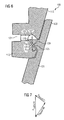
- a section through the stone support ring 113 along the line VV in FIG. 4 is in FIG. 5 shown. It can be seen in this that the through holes 123 do not extend in the radial direction of the support ring 113, but are inclined in the circumferential direction and enclose an angle of about 60 ° with the radial direction.
- the stone support ring 113 of the flame tube 101 is inserted into the receiving portion 109 of the mixing housing 107.
- This receiving portion 109 is formed by pinnacles 133, which are formed in the wall 131 of the mixing housing.
- the pinnacles 133 are in this case formed by a wall section of the mixing housing, which is penetrated by circumferentially distributed around the mixing housing recesses or recesses. These recesses or recesses extend from the edge of the peripheral wall, starting substantially in the axial direction of the flange into the peripheral wall.
- the receiving section 109 is given an increased flexibility with respect to the wall section of the mixing housing 107 which is not provided with the recesses or recesses, so that forces occurring between the mixing housing 107 and the flame tube 101 can be compensated to a certain extent.
- the inner sides 135 of the pinnacles 133 are planar and provided with an armor 137.
- the armor 137 of the merlons is harder than the armor 129 of the outside 115 of the stone support ring 113, so that occurring during operation abrasion caused by friction of the stone support ring 113 on the inside of the pinnacles 133, to a large extent on the stone support ring 113 concentrated.
- FIG. 6 shows a section of the stone support ring 113 and the receiving portion 109 when the combustion chamber assembly has reached a certain operating time.
- the Zinnenkranz of the mixing housing 107 grinds into the stone support ring 113 of the flame tube 101, if no previous findings and replacement or repair takes place. This condition is in FIG. 6 shown.
- the grinding creates a projection 139 in the pinnacles 133, which protrudes into the outer groove 119, that is, into the cooling air passage.
- this projection 139 has an oblique side 141 which is largely parallel to the oblique groove wall 125.
- the oblique groove wall 125 and the oblique side 141 created during grinding in the projections 139 of the pinnacles thus lead to a bevelled contact surface in relation to the radial direction and the axial direction of the two components, which uses or generates the forces generated by transient movement of the components with temperature changes ., converts the components independently of each other, ie, they are pushed apart, and the forces that occur do not cause any consequential damage, such as tearing of battlements, deformation, etc.
- a force diagram which transiently the force F caused by transient motion and the force exerted on the flame tube resultant force F and the resulting result.Fl the mixing housing force F result.Mi shows, in FIG. 7 shown.
- the curved side 127 of the outer groove 119 in the stone support ring 113 also causes even with considerable wear and an associated deep digging of the pinnacles 133 in the outer groove 119 of the stone support ring 113 always given a sufficiently large cooling air passage for the stone support ring is. An obstruction of thedeluftpasssage can be avoided.
- the groove wall 127 opposite the inclined groove wall 125 is curved
- the groove wall can be roof-shaped, that is to say with two planar wall sections which meet one another at an angle. In the simplest case, this can be realized by a rectangular in cross-section groove is introduced at an angle relative to the radial direction of the stone support ring 113 in the outside 115.
- the angle which the groove encloses with the radial direction is in this case preferably in the range between 30 ° and 60 °. In order to avoid blockage of the cooling air passage by a deeper incorporation of the battlements (abandoned by a longer operation), they can be introduced beyond the height of the possible incorporated batt in the support ring.
- the stone support ring is provided in the region of the groove (cooling air supply) with a slope (for example 40 °, but the slope is variable and functionally selected), which has a forced demolition of mixing housing and stone support ring result in cooling of the components.
- a slope for example 40 °, but the slope is variable and functionally selected
Landscapes
- Engineering & Computer Science (AREA)
- Chemical & Material Sciences (AREA)
- Combustion & Propulsion (AREA)
- Mechanical Engineering (AREA)
- General Engineering & Computer Science (AREA)
- Ceramic Engineering (AREA)
- Turbine Rotor Nozzle Sealing (AREA)
- Combustion Of Fluid Fuel (AREA)
- Gas Burners (AREA)
- Portable Nailing Machines And Staplers (AREA)
Description
- Die vorliegende Erfindung betrifft einen Stützring für Hitzeschildelemente eines Flammenrohrs, insbesondere eines Flammenrohrs einer Gasturbine. Daneben betrifft die Erfindung eine Brennkammeranordnung mit einem Flammenrohr und einem Mischgehäuse, wie sie insbesondere bei Gasturbinen Verwendung findet.
- Stützringe für Hitzeschildelemente, wie sie insbesondere bei Gasturbinenflammenrohren zum Einsatz kommen, können eine an ihrer Außenseite verlaufende Nut aufweisen, die als Kühlluftpassage dient. Ein Ausschnitt aus einem Stützring nach Stand der Technik ist in
Figur 1 dargestellt, wobei der Stützring vom Zinnenkranz eines Mischgehäuses aufgenommen ist. Die Figur zeigt einen Ausschnitt des Stützrings 1 sowie einen Ausschnitt einer Zinne 3 eines Mischgehäuses in einer schematisierten Querschnittsansicht. Der Stützring weist einen verstärkten Bereich 5 auf, welcher wiederum mit einer inneren Nut 7 und einer äußeren Nut 9 versehen ist, die sich beide über den vollen Umfang des Stützringes erstrecken. Die äußere Nut 9 und die innere Nut 7 sind über eine Anzahl radialer Durchgangsbohrungen 11 fluidtechnisch miteinander verbunden. Die äußere Nut 9 bildet eine Frischluftzufuhr zum Kühlen des Stützringes 1. Die Frischluft wird dann durch die Bohrungen 11 ins Brennkammerinnere weitergeleitet. Der verstärkte Bereich 5 bildet außerdem einen zum Inneren der Brennkammer hin vorstehenden flanschartigen Vorsprung, der eine Auflage für Hitzeschildelemente bildet. - Die während des Betriebs der Gasturbine herrschenden Temperaturen führen auf Grund unterschiedlicher thermischer Ausdehnungskoeffizienten des Stützringes 1 und der Zinnen 3 dazu, dass sich die Zinnen 3 während des Betriebs der Gasturbine in den Stützring 1 einschleifen. Die Folge des Einschleifens ist in
Figur 2 dargestellt. Auf Grund von Materialabtrag bilden sich in den Zinnen 3 Vorsprünge 13 aus, die in die äußere Nut 9 des Stützrings 1 eingreifen. Wenn nun die Gasturbine abgeschaltet wird, kontrahieren der Stützring 1 und die Zinnen 3 auf Grund der unterschiedlichen thermischen Ausdehnungskoeffizienten verschieden, so dass der Stützring 1 eine Kraft FF1 auf die Zinnen 3 ausübt, während die Zinnen 3 eine Kraft FMi auf den Stützring ausüben. Diese Kräfte führen dazu, dass sich der Stützring 1 und die Zinnen ineinander verhaken, wobei während der Abkühlung enorme Kräfte auftreten, die gravierende Folgen haben können, wenn die Zinnen 3 oder der Stützring nicht rechtzeitig ausgebessert oder ausgetauscht werden. Es erfolgen daher regelmäßige Inspektionen des Übergangs zwischen dem Mischgehäuse und dem Flammenrohr, wobei die Zeitdauer zwischen zwei Inspektionen durch den beschriebenen Einschleifprozess festgelegt ist. - Aufgabe der vorliegenden Erfindung ist es, einen vorteilhaften Stützring und einen vorteilhafte Brennkammeranordnung zur Verfügung zu stellen, die es insbesondere ermöglichen, die Wartungsintervalle für den Übergang zwischen Flammenrohr und Mischgehäuse zu verlängern.
- Diese Aufgabe wird durch einen Stützring für Hitzeschildelemente eines Flammenrohrs nach Anspruch 1 und eine Brennkammeranordnung mit einem Flammenrohr und einem Mischgehäuse nach Anspruch 7 gelöst. Die abhängigen Ansprüche enthalten vorteilhafte Ausgestaltung der Erfindung.
- In der Außenseite eines erfindungsgemäßen Stützringes für Hitzschildelemente eines Flammenrohrs, insbesondere eines Gasturbinenflammenrohrs, ist wenigstens eine Nut vorhanden. Diese weist eine bezogen auf die radiale Richtung des Stützringes schräg verlaufende Nutwand auf. Geeignete Winkel zwischen der Oberflächennormalen der schräg verlaufenden Nutwand zur Radialrichtung des Stützringes liegen insbesondere im Bereich zwischen 30° und 60°.
- Die schräg verlaufende Nutwand führt beim Einschleifen des Zinnenkranzes eines Mischgehäuses in den Stützring dazu, dass sich ein keilförmiger Vorsprung in den Zinnen ausbildet. Dieser weist eine der schrägen Nutwand entsprechende Keilfläche auf. Wenn nun beim Ausschalten der Gasturbine auf Grund des unterschiedlichen thermischen Ausdehnungsverhaltens von Mischgehäuse und Stützring in Axialrichtung des Stützringes wirkende Kräfte auftreten, führt die Schräge dazu, dass in Radialrichtung des Stützringes wirkende Kräfte generiert werden, welche die Zinnen vom Stützring trennen. Hierdurch wird insbesondere das Abreißen von Zinnen auf Grund einer zu großen Kraft in Axialrichtung des Stützringes vermieden.
- Im Bereich der Nut können sich insbesondere Durchgangsöffnungen befinden, die sich von der Außenseite des Stützringes zu seiner Innenseite erstrecken und als Kühlluftöffnungen zum Kühlen des Stützringes sowie zur Abfuhr von durch die Nut eingebrachter Kühlluft dienen. Um zu vermeiden, dass die Frischluftzufuhr durch die Nut unterbunden wird, wenn die Zinnen tief in die Nut des Stützringes eingeschliffen sind, kann die der schrägen Nutwand gegenüberliegende Nutwand eine nicht-planare Geometrie aufweisen. Insbesondere kann sie eine in Axialrichtung des Stützringes gekrümmte Fläche bilden.
- Um den Materialverlust an der Außenseite des Stützringes beim Einschleifen zu verringern und dadurch den Einschleifprozess zu verlangsamen, kann seine Außenseite eine Panzerung, d.h. eine abriebresistente Schicht (hard-facing, wear-resistant layer) aufweisen.
- Eine erfindungsgemäße Brennkammeranordnung weist ein Flammenrohr und eine Mischgehäuse auf. Sie kann insbesondere bei Gasturbinen zum Einsatz kommen. Das Flammenrohr besitzt ein Ausgangsende mit einem Stützring für Hitzeschildelemente, insbesondere für keramische Hitzeschildelemente. Das Mischgehäuse weist einen Rand mit vorstehenden Zinnen auf, wobei die Zinnen einen Aufnahmeabschnitt zum Aufnehmen des Stützringes bilden. In der erfindungsgemäßen Brennkammeranordnung ist der Stützring als erfindungsgemäßer Stützring ausgebildet. Die mit Bezug auf den erfindungsgemäßen Stützring beschriebenen Wirkungen und Vorteile ergeben sich daher insbesondere auch bei der erfindungsgemäßen Brennkammer, weswegen auf die Beschreibung der Wirkung und Vorteile des Stützringes verwiesen wird.
- Um das Einschleifen zu verlangsamen, können neben der Außenseite des Stützringes auch die Innenseiten der Zinnen eine Panzerung aufweisen. Insbesondere kann die Panzerung der Zinnen härter als die Panzerung des Stützringes sein. Selbstverständlich kann die Panzerung aber auch gleich sein, oder die Panzerung des Stützringes kann härter sein, als die Panzerung der Zinnen. Vorzugsweise ist jedoch die Panzerung der Zinnen härter als die des Stützringes, da ein Ausbessern und Austauschen des Stützringes im Vergleich zu einem Ausbessern oder Austauschen von Zinnen den geringeren Aufwand darstellt. Außerdem ist ein Abriss von Zinnen bei gleicher Panzerung wahrscheinlicher als eine Beschädigung des Stützringes und hat für die Gasturbine die kritischern Folgen. Durch die geeignet Wahl der Härte der Panzerung ist es also möglich, die Verteilung des Verschleißes auf den Stützring und die Zinnen zu steuern.
- Weitere Merkmale, Eigenschaften und Vorteile der Erfindung ergeben sich aus der nachfolgenden Beschreibung eines Ausführungsbeispiels unter Bezugnahme auf die beiliegenden Figuren.
-
Figur 1 zeigt einen Ausschnitt eines Stützringes in einem Zinnenkranz gemäß Stand der Technik. -
Figur 2 zeigt den Ausschnitt ausFigur 1 nach einem betriebsbedingten Einschleifen des Zinnenkranzes in den Stützring -
Figur 3 zeigt eine erfindungsgemäße Brennkammeranordnung mit Flammenrohr und Mischgehäuse in einer schematischen Darstellung. -
Figur 4 zeigt einen Ausschnitt des Übergangs zwischen Flammenrohr und Mischgehäuse in einer vergrößerten Schnittansicht. -
Figur 5 zeigt einen Schnitt entlang der Linie V-V inFigur 4 . -
Figur 6 zeigt den Stützring und die Zinnen des Mischgehäuses nach einem betriebsbedingten Einschleifen. -
Figur 7 zeigt ein Diagramm mit den beim Abkühlen der Brennkammeranordnung auftretenden Kräften. - Eine erfindungsgemäße Brennkammeranordnung, die einen erfindungsgemäßen Stützring für Hitzschildelemente, auch Steinstützring genannt, aufweist, wird nachfolgend mit Bezug auf die
Figuren 3 bis 7 beschrieben. Das vorliegende Ausführungsbeispiel zeigt eine Brennkammeranordnung, in der das Flammenrohr vertikal angeordnet ist, d.h. die Axialrichtung des Flammenrohrs verläuft in vertikaler Richtung. Entsprechend stellen die Radialrichtungen des Flammenrohr horizontale Richtungen dar. Das in vertikaler Richtung aus dem Flammerohr ausströmende Heißgas wird von dem Mischgehäuse in eine horizontale Strömungsrichtung umgelenkt. -
Figur 3 zeigt die Brennkammeranordnung, welche ein Flammenrohr 101 mit einem Brennerende 103, an dem die Brenner (nicht dargestellt) angeordnet sind, und einem Austrittsende 105, aus dem die in der Brennkammer entstehenden Heißgase auftreten, aufweist, in eine Schnittansicht. Das Flammenrohr 101 ist mit seinem Austrittsende 105 in eine Aufnahme 109 eines Mischgehäuses 107 eingeführt. Das Mischgehäuse leitet die aus dem Flammenrohr 101 austretenden Heißgase zur Turbine (nicht dargstellt) weiter. - Das Innere des Flammenrohrs 101 ist mit keramischen Hitzeschildelementen, auch Hitzeschildsteine genannt, versehen, um die Brennkammerwand vor dem korrosiven Heißgas zu schützen. Am Austrittsende des Flammenrohrs 101 ist der die Hitzeschildsteine 111 haltende Steinstützring 113 angeordnet, von dem sich ein wesentlicher Teil in der Aufnahme 109 des Mischgehäuses 107 befindet. Der Aufnahmeabschitt 109 und der Steinstützring 113 sind in
Figur 4 ausschnittsweise vergrößert dargestellt. - Der Steinstützring 113 weist eine Außenseite 115 und eine Innenseite 117 auf. Sowohl in der Außenseite 115, als auch in der Innenseite 117 sind Nuten 119, 121 vorhanden, die sich über den gesamten Umfang des Steinstützringes 113 erstrecken. Die Außenseite des Steinstützringes 113 ist zudem mit einer abriebmindernden Panzerung 129 versehen. In regelmäßigen Abständen um dem Umfang des Steinstützringes 113 verteilt sind Durchgangsbohrungen 123 vorhanden, welche die Nut 119 in der Außenseite 117 (im Folgenden Außennut 119 genannt) mit der in der Innenseite 117 ausgebildeten Nut 121 (im Folgenden Innennut 121 genannt) strömungstechnisch verbinden. Die Außennut 119 dient als Kühlluftpassage, welche das Verteilen von Kühlluft um den Steinstützring 113 herum ermöglicht. Die Kühlluft kann dann aus der Außennut 119 durch die Durchgangsbohrungen 123 in die Innennut 121 und von dort in Brennkammerinnnere gelangen. Die Außennut 117 und die Innennut 121 sind in einem flanschartigen Vorsprung 122 angeordnet, der in Radialrichtung zum Brennkammerinneren hin vorsteht. Die Oberseite 124 des Vorsprungs 122 bildet eine Stützfläche für die unterste Reihe der Hitzeschildelemente 111 (siehe
Figur 3 ). - Die Außennut 119 des Steinstützringes 113 weist eine bezogen auf die Radialrichtung des Steinstützringes 113 schräge Nutwand 125 auf. Die Oberflächennormale der schrägen Nutwand 125 schließt mit der Radialrichtung des Stützringes 113 einen Winkel zwischen 30° und 60° ein. Im vorliegenden Ausführungsbeispiel beträgt der Winkel ca. 40°. Die der schrägen Nutwand 125 gegenüberliegende Nutwand 127 besitzt eine nicht-planare Geometrie und ist im vorliegenden Ausführungsbeispiel in Axialrichtung des Stützringes 113 gekrümmt.
Ein Schnitt durch den Steinstützring 113 entlang der Linie V-V inFigur 4 ist inFigur 5 dargestellt. Darin ist zu erkennen, dass die Durchgangsbohrungen 123 nicht in Radialrichtung des Stützringes 113 verlaufen, sondern in Umfangsrichtung geneigt sind und mit der Radialrichtung einen Winkel von ca. 60° einschließen. - Der Steinstützring 113 des Flammenrohrs 101 ist in den Aufnahmeabschnitt 109 des Mischgehäuses 107 eingeschoben. Dieser Aufnahmeabschnitt 109 wird von Zinnen 133 gebildet, die in der Wand 131 des Mischgehäuses ausgebildet sind. Die Zinnen 133 sind hierbei von einem Wandabschnitt des Mischgehäuses gebildet, der von in Umfangsrichtung um das Mischgehäuse verteilten Ausnehmungen oder Aussparungen durchsetzt ist. Diese Ausnehmungen beziehungsweise Aussparungen erstrecken sich vom Rand der Umfangswand ausgehend im wesentlichen in Axialrichtung des Flansches in die Umfangswand hinein. Dadurch erhält der Aufnahmeabschnitt 109 gegenüber dem nicht mit den Ausnehmungen beziehungsweise Aussparungen versehenen Wandabschnitt des Mischgehäuses 107 eine erhöhte Flexibilität, so dass sich zwischen dem Mischgehäuse 107 und dem Flammenrohr 101 auftretende Kräfte bis zu einem gewissen Grad kompensieren lassen.
- Die Innenseiten 135 der Zinnen 133 sind planar und mit einer Panzerung 137 versehen. Im vorliegenden Ausführungsbeispiel ist die Panzerung 137 der Zinnen härter als die Panzerung 129 der Außenseite 115 des Steinstützringes 113, so dass sich im Betrieb auftretender Abrieb, der durch Reibung des Steinstützringes 113 an der Innenseite der Zinnen 133 entsteht, zu einem großen Teil auf den Steinstützring 113 konzentriert.
-
Figur 6 zeigt einen Ausschnitt aus dem Steinstützring 113 und dem Aufnahmeabschnitt 109, wenn die Brennkammeranordnung eine bestimmte Betriebsdauer erreicht hat. Während des Betriebs schleift sich der Zinnenkranz des Mischgehäuses 107 in den Steinstützring 113 des Flammenrohrs 101 ein, wenn keine vorherige Befundung und ein Austausch bzw. eine Reparatur stattfindet. Dieser Zustand ist inFigur 6 dargestellt. Durch das Einschleifen entsteht in den Zinnen 133 ein Vorsprung 139, der in die Außennut 119, also in die Kühlluftpassage, vorsteht. Dieser Vorsprung 139 weist abbriebbedingt eine zur schrägen Nutwand 125 weitgehend parallele schräge Seite 141 auf. - Wenn das Flammenrohr 101 und das Mischgehäuse 107 nach dem Ausschalten der Gasturbine abkühlen treten zwischen der abgeschrägten Seite 141 des Vorsprungs 139 und der schrägen Nutwand 125 des Stützringes 113 in Axialrichtung wirkende Kräfte FMi und FF1 auf, die aus der beim Abkühlen resultierenden axialen Relativbewegung der beiden Bauteile entstehen. Durch die beim Einscheifen aufgrund der abgeschrägten Nutwand 125 entstehende keilartige Form der Vorsprünge 139 wird eine zwischen dem Steinstützring 113 und den Zinnen 133 entgegen gesetzt wirkende radiale Kraft (horizontal) erzeugt, die diese Bauteile auseinander drückt und so von einander trennt. Hierdurch wird ein Abreißen der Zinnen auf Grund einer zu hohen axialen Kraft vermieden. Die schräge Nutwand 125 und die beim Einschleifen entstehende schräge Seite 141 in den Vorsprüngen 139 der Zinnen führen also zu einer im Bezug auf die Radialrichtung und die Axialrichtung der beiden Bauteile abgeschrägten Kontaktfläche, welche die durch transiente Bewegung der Bauteile bei Temperaturänderungen generierten Kräfte derart nutzt bzw. umwandelt, dass sich die Bauteile selbständig von einander lösen, d.h. auseinander geschoben werden, und die auftretenden Kräfte keinen Folgeschaden wie etwa einen Abriss von Zinnen, eine Verformung, etc. verursachen. Ein Kräftediagramm, welches die durch transiente Bewegung verursachte Kraft Ftransient und die auf das Flammenrohr ausgeübte resultierende Kraft Fresult.Fl sowie die auf das Mischgehäuse resultierende Kraft Fresult.Mi zeigt, ist in
Figur 7 dargestellt. - Die gekrümmte Seite 127 der Außennut 119 im Steinstützring 113 führt außerdem dazu, dass auch bei erheblichen Verschleiß und einem damit verbundenen tiefen Eingraben der Zinnen 133 in die Außennut 119 des Steinstützringes 113 immer eine ausreichend große Kühlluftpassage für den Steinstützring gegeben ist. Ein Versperren der Kühlluftpasssage kann so vermieden werden.
- Obwohl das Versperren der Kühlluftpassage im vorliegenden Ausführungsbeispiel dadurch vermieden wird, dass die der schrägen Nutwand 125 gegenüberliegende Nutwand 127 gekrümmt ist, können auch andere nicht-planare Geometrien dieser Nutwand zum selben Ergebnis führen. Bspw. kann die Nutwand dachförmig ausgebildet sein, also mit zwei unter einem Winkel aufeinander treffenden planaren Wandabschnitten. Im einfachsten Fall kann dies realisiert werden, indem eine im Querschnitt rechteckige Nut in einem Winkel relativ zur Radialrichtung des Steinstützringes 113 in dessen Außenseite 115 eingebracht wird. Der Winkel, den die Nut mit der Radialrichtung einschließt, liegt hierbei vorzugsweise im Bereich zwischen 30° und 60°. Um durch ein tieferes Einarbeiten der Zinnen (aufgegeben durch einen längeren Betrieb) ein Versperren der Kühlluftpassage zu vermeiden, können diese über die Höhe der möglichen eingearbeiteten Zinne hinaus in den Stützring eingebracht sein.
- Gemäß der Erfindung wird also der Steinstützring im Bereich der Nut (Kühlluftversorgung) mit einer Schräge versehen (z.B. 40°, die Steigung ist aber variabel und funktionsbedingt zu wählen), die beim Abkühlen der Bauteile eine Zwangsentformung von Mischgehäuse und Steinstützring zur Folge hat. Durch die Ausformung eines "Keils" wird eine entgegengesetzte Kraft (horizontal) auf den Stützring und das Mischgehäuse erzeugt, die diese Bauteile von einander "trennt". Hierdurch wird ein Abreißen der Zinnen auf Grund einer zu hohen vertikalen Kraft vermieden.
Claims (9)
- Stützring (113) für Hitzeschildelemente (111) eines Flammrohrs (101), wobei in der Außenseite (115) des Stützrings wenigstens eine Nut (119) vorhanden ist,
dadurch gekennzeichnet, dass - die Nut (119) eine bezogen auf die Radialrichtung des Stützrings (113) schräg verlaufende Nutwand (125)aufweist. - Stützring (113) nach Anspruch 1,
dadurch gekennzeichnet, dass
die Oberflächennormale der schräg verlaufenden Nutwand (125) einen Winkel im Bereich zwischen 30° und 60° zur Radialrichtung des Stützrings (113) aufweist. - Stützring (113) nach Anspruch 1 oder Anspruch 2,
dadurch gekennzeichnet, dass
sich im Bereich der Nut (119) Durchgangsöffnungen (123) befinden, die sich von der Außenseite (115) des Stützrings (113) zu seiner Innenseite (117) erstrecken. - Stützring (113) nach Anspruch 3,
dadurch gekennzeichnet, dass
die der schrägen Nutwand (125) gegenüber liegende Nutwand (127) eine nicht planare Geometrie besitzt. - Stützring (113) nach Anspruch 4,
dadurch gekennzeichnet, dass
die der schrägen Nutwand (125) gegenüber liegende Nutwand (127) eine in Axialrichtung des Stützringes (113) gekrümmte Fläche bildet. - Stützring (113) nach einem der Ansprüche 1 bis 5,
dadurch gekennzeichnet, dass
die Außenseite (115) des Stützringes (113) eine Panzerung aufweist. - Brennkammeranordnung mit einem Flammrohr (101) und einem Mischgehäuse (107), wobei das Flammrohr (101) ein Ausgangsende (105) mit einem Stützring (113) für Hitzeschildelemente (111) und das Mischgehäuse (107) einen Rand mit vorstehenden Zinnen (133) aufweist, wobei die Zinnen (133) einen Aufnahmeabschnitt (109) zum Aufnehmen des Stützringes (113) bilden, dadurch gekennzeichnet, dass der Stützring (113) nach einem der Ansprüche 1 bis 6 ausgebildet ist.
- Brennkammeranordnung nach Anspruch 7,
dadurch gekennzeichnet, dass
die Innenseiten (135) der Zinnen (133) und/oder die Außenseite (115) des Stützringes (113) jeweils eine Panzerung aufweist bzw. aufweisen. - Brennkammeranordnung nach Anspruch 8,
dadurch gekennzeichnet, dass
die Panzerung der Zinnen (133) härter als die Panzerung des Stützringes (113) ist.
Priority Applications (1)
| Application Number | Priority Date | Filing Date | Title |
|---|---|---|---|
| PL08842468T PL2201299T3 (pl) | 2007-10-26 | 2008-10-23 | Pierścień podporowy dla elementów osłony cieplnej płomienicy i układ komory spalania z tego rodzaju pierścieniem podporowym |
Applications Claiming Priority (2)
| Application Number | Priority Date | Filing Date | Title |
|---|---|---|---|
| DE102007051649 | 2007-10-26 | ||
| PCT/EP2008/064333 WO2009053417A2 (de) | 2007-10-26 | 2008-10-23 | Stützring für hitzeschildelemente eines flammenrohrs und eine brennkammeranordnung mit einem derartigen stützring |
Publications (2)
| Publication Number | Publication Date |
|---|---|
| EP2201299A2 EP2201299A2 (de) | 2010-06-30 |
| EP2201299B1 true EP2201299B1 (de) | 2011-05-11 |
Family
ID=40340467
Family Applications (1)
| Application Number | Title | Priority Date | Filing Date |
|---|---|---|---|
| EP08842468A Active EP2201299B1 (de) | 2007-10-26 | 2008-10-23 | Stützring für hitzeschildelemente eines flammenrohrs und eine brennkammeranordnung mit einem derartigen stützring |
Country Status (6)
| Country | Link |
|---|---|
| EP (1) | EP2201299B1 (de) |
| CN (1) | CN101855497B (de) |
| AT (1) | ATE509236T1 (de) |
| PL (1) | PL2201299T3 (de) |
| RU (1) | RU2478881C2 (de) |
| WO (1) | WO2009053417A2 (de) |
Families Citing this family (2)
| Publication number | Priority date | Publication date | Assignee | Title |
|---|---|---|---|---|
| DE102012204103A1 (de) * | 2012-03-15 | 2013-09-19 | Siemens Aktiengesellschaft | Hitzeschildelement für einen Verdichterluftbypass um die Brennkammer |
| DE102017207392A1 (de) * | 2017-05-03 | 2018-11-08 | Siemens Aktiengesellschaft | Silobrennkammer und Verfahren zum Umrüsten einer solchen |
Family Cites Families (7)
| Publication number | Priority date | Publication date | Assignee | Title |
|---|---|---|---|---|
| DE8618859U1 (de) * | 1986-07-14 | 1988-01-28 | Siemens AG, 1000 Berlin und 8000 München | Hitzeschild |
| ES2051519T3 (es) * | 1990-07-17 | 1994-06-16 | Siemens Ag | Trozo de tubo, especialmente tubo de combustion con bastidor de apoyo refrigerado para un revestimiento resistente al calor. |
| US5749218A (en) * | 1993-12-17 | 1998-05-12 | General Electric Co. | Wear reduction kit for gas turbine combustors |
| GB2298267B (en) * | 1995-02-23 | 1999-01-13 | Rolls Royce Plc | An arrangement of heat resistant tiles for a gas turbine engine combustor |
| RU2212591C1 (ru) * | 2002-05-16 | 2003-09-20 | Открытое акционерное общество "Научно-производственное объединение "Сатурн" | Кольцевая камера сгорания газотурбинного двигателя |
| RU2300706C2 (ru) * | 2005-05-05 | 2007-06-10 | Открытое акционерное общество "Авиадвигатель" | Трубчато-кольцевая камера сгорания газотурбинного двигателя |
| WO2008017550A1 (de) * | 2006-08-07 | 2008-02-14 | Alstom Technology Ltd | Brennkammer einer verbrennungsanlage |
-
2008
- 2008-10-23 AT AT08842468T patent/ATE509236T1/de active
- 2008-10-23 CN CN2008801132621A patent/CN101855497B/zh active Active
- 2008-10-23 RU RU2010121163/06A patent/RU2478881C2/ru active
- 2008-10-23 EP EP08842468A patent/EP2201299B1/de active Active
- 2008-10-23 WO PCT/EP2008/064333 patent/WO2009053417A2/de not_active Ceased
- 2008-10-23 PL PL08842468T patent/PL2201299T3/pl unknown
Also Published As
| Publication number | Publication date |
|---|---|
| CN101855497A (zh) | 2010-10-06 |
| CN101855497B (zh) | 2012-09-05 |
| RU2010121163A (ru) | 2011-12-10 |
| PL2201299T3 (pl) | 2011-10-31 |
| ATE509236T1 (de) | 2011-05-15 |
| WO2009053417A2 (de) | 2009-04-30 |
| EP2201299A2 (de) | 2010-06-30 |
| WO2009053417A3 (de) | 2010-05-20 |
| RU2478881C2 (ru) | 2013-04-10 |
Similar Documents
| Publication | Publication Date | Title |
|---|---|---|
| DE602004011859T2 (de) | Vorrichtung für die Regelung von Spalten in einer Gasturbine | |
| DE102005060961B4 (de) | Gasturbine | |
| DE102011009409B4 (de) | Spinne für die Verwendung mit einem Kreiselbrecher sowie Kreiselbrecher mit einer Spinne | |
| DE102004023879B4 (de) | Axialdampfturbine | |
| EP2196734A1 (de) | Brennstofflanze für einen Brenner | |
| DE102015100874A1 (de) | Dichtungseinrichtung zur Erbringung einer Abdichtung in einer Turbomaschine | |
| DE102016205320A1 (de) | Turbinenschaufel mit Kühlstruktur | |
| DE102011105762A1 (de) | Kippsegmentlager | |
| DE102012100013A1 (de) | Axiale Haltevorrichtung für ein Turbinensystem | |
| DE112016006522T5 (de) | Lagervorrichtung und Rotationsmaschine | |
| EP2201299B1 (de) | Stützring für hitzeschildelemente eines flammenrohrs und eine brennkammeranordnung mit einem derartigen stützring | |
| EP3134682A1 (de) | Brenneranordnung | |
| WO2014170071A1 (de) | VERSCHLEIßANZEIGE IN EINEM VERBUNDSYSTEM AUS FEUERFESTEN KERAMISCHEN STEINEN | |
| DE10303340A1 (de) | Kühleinrichtung | |
| DE2158578A1 (de) | Stator-Schaufelkonstruktion | |
| WO2005019731A1 (de) | Brennkammer, insbesondere gasturbinenbrennkammer | |
| DE102006015327B4 (de) | Kolbenstangendichtring | |
| DE102005046731A1 (de) | Hitzeschildanordnung | |
| EP2024684B1 (de) | Gasturbine mit gepanzerten maschinenkomponenten | |
| WO2015074787A1 (de) | Ein dichtungsring einer dampfturbinen welche zwischen zwei gehäusehälften in ringnuten positioniert ist | |
| EP3593048B1 (de) | Silobrennkammer und verfahren zum umrüsten einer solchen | |
| EP4279769B1 (de) | Rostfeuerung mit einem rostdurchfalltrichter | |
| AT512609A1 (de) | Federelement | |
| EP2712704B1 (de) | Topfschleifscheibe | |
| EP3046700B1 (de) | Elektrolichtbogenofen mit mehreren bodenabstichöffnungen |
Legal Events
| Date | Code | Title | Description |
|---|---|---|---|
| PUAI | Public reference made under article 153(3) epc to a published international application that has entered the european phase |
Free format text: ORIGINAL CODE: 0009012 |
|
| 17P | Request for examination filed |
Effective date: 20100326 |
|
| AK | Designated contracting states |
Kind code of ref document: A2 Designated state(s): AT BE BG CH CY CZ DE DK EE ES FI FR GB GR HR HU IE IS IT LI LT LU LV MC MT NL NO PL PT RO SE SI SK TR |
|
| AX | Request for extension of the european patent |
Extension state: AL BA MK RS |
|
| GRAP | Despatch of communication of intention to grant a patent |
Free format text: ORIGINAL CODE: EPIDOSNIGR1 |
|
| RTI1 | Title (correction) |
Free format text: SUPPORT RING FOR HEAT SHIELD ELEMENTS ON A FLAME TUBE AND A COMBUSTION CHAMBER ARRANGEMENT WITH SAID SUPPORT RING |
|
| GRAS | Grant fee paid |
Free format text: ORIGINAL CODE: EPIDOSNIGR3 |
|
| GRAA | (expected) grant |
Free format text: ORIGINAL CODE: 0009210 |
|
| DAX | Request for extension of the european patent (deleted) | ||
| AK | Designated contracting states |
Kind code of ref document: B1 Designated state(s): AT BE BG CH CY CZ DE DK EE ES FI FR GB GR HR HU IE IS IT LI LT LU LV MC MT NL NO PL PT RO SE SI SK TR |
|
| REG | Reference to a national code |
Ref country code: GB Ref legal event code: FG4D Free format text: NOT ENGLISH |
|
| REG | Reference to a national code |
Ref country code: CH Ref legal event code: EP |
|
| REG | Reference to a national code |
Ref country code: IE Ref legal event code: FG4D |
|
| REG | Reference to a national code |
Ref country code: DE Ref legal event code: R096 Ref document number: 502008003528 Country of ref document: DE Effective date: 20110622 |
|
| REG | Reference to a national code |
Ref country code: NL Ref legal event code: T3 |
|
| PG25 | Lapsed in a contracting state [announced via postgrant information from national office to epo] |
Ref country code: SE Free format text: LAPSE BECAUSE OF FAILURE TO SUBMIT A TRANSLATION OF THE DESCRIPTION OR TO PAY THE FEE WITHIN THE PRESCRIBED TIME-LIMIT Effective date: 20110511 Ref country code: PT Free format text: LAPSE BECAUSE OF FAILURE TO SUBMIT A TRANSLATION OF THE DESCRIPTION OR TO PAY THE FEE WITHIN THE PRESCRIBED TIME-LIMIT Effective date: 20110912 Ref country code: LT Free format text: LAPSE BECAUSE OF FAILURE TO SUBMIT A TRANSLATION OF THE DESCRIPTION OR TO PAY THE FEE WITHIN THE PRESCRIBED TIME-LIMIT Effective date: 20110511 Ref country code: NO Free format text: LAPSE BECAUSE OF FAILURE TO SUBMIT A TRANSLATION OF THE DESCRIPTION OR TO PAY THE FEE WITHIN THE PRESCRIBED TIME-LIMIT Effective date: 20110811 |
|
| REG | Reference to a national code |
Ref country code: PL Ref legal event code: T3 |
|
| REG | Reference to a national code |
Ref country code: HU Ref legal event code: AG4A Ref document number: E011564 Country of ref document: HU |
|
| PG25 | Lapsed in a contracting state [announced via postgrant information from national office to epo] |
Ref country code: GR Free format text: LAPSE BECAUSE OF FAILURE TO SUBMIT A TRANSLATION OF THE DESCRIPTION OR TO PAY THE FEE WITHIN THE PRESCRIBED TIME-LIMIT Effective date: 20110812 Ref country code: FI Free format text: LAPSE BECAUSE OF FAILURE TO SUBMIT A TRANSLATION OF THE DESCRIPTION OR TO PAY THE FEE WITHIN THE PRESCRIBED TIME-LIMIT Effective date: 20110511 Ref country code: ES Free format text: LAPSE BECAUSE OF FAILURE TO SUBMIT A TRANSLATION OF THE DESCRIPTION OR TO PAY THE FEE WITHIN THE PRESCRIBED TIME-LIMIT Effective date: 20110822 Ref country code: IS Free format text: LAPSE BECAUSE OF FAILURE TO SUBMIT A TRANSLATION OF THE DESCRIPTION OR TO PAY THE FEE WITHIN THE PRESCRIBED TIME-LIMIT Effective date: 20110911 Ref country code: CY Free format text: LAPSE BECAUSE OF FAILURE TO SUBMIT A TRANSLATION OF THE DESCRIPTION OR TO PAY THE FEE WITHIN THE PRESCRIBED TIME-LIMIT Effective date: 20110511 Ref country code: LV Free format text: LAPSE BECAUSE OF FAILURE TO SUBMIT A TRANSLATION OF THE DESCRIPTION OR TO PAY THE FEE WITHIN THE PRESCRIBED TIME-LIMIT Effective date: 20110511 Ref country code: SI Free format text: LAPSE BECAUSE OF FAILURE TO SUBMIT A TRANSLATION OF THE DESCRIPTION OR TO PAY THE FEE WITHIN THE PRESCRIBED TIME-LIMIT Effective date: 20110511 |
|
| REG | Reference to a national code |
Ref country code: IE Ref legal event code: FD4D |
|
| PG25 | Lapsed in a contracting state [announced via postgrant information from national office to epo] |
Ref country code: EE Free format text: LAPSE BECAUSE OF FAILURE TO SUBMIT A TRANSLATION OF THE DESCRIPTION OR TO PAY THE FEE WITHIN THE PRESCRIBED TIME-LIMIT Effective date: 20110511 Ref country code: CZ Free format text: LAPSE BECAUSE OF FAILURE TO SUBMIT A TRANSLATION OF THE DESCRIPTION OR TO PAY THE FEE WITHIN THE PRESCRIBED TIME-LIMIT Effective date: 20110511 Ref country code: IE Free format text: LAPSE BECAUSE OF FAILURE TO SUBMIT A TRANSLATION OF THE DESCRIPTION OR TO PAY THE FEE WITHIN THE PRESCRIBED TIME-LIMIT Effective date: 20110511 |
|
| PG25 | Lapsed in a contracting state [announced via postgrant information from national office to epo] |
Ref country code: RO Free format text: LAPSE BECAUSE OF FAILURE TO SUBMIT A TRANSLATION OF THE DESCRIPTION OR TO PAY THE FEE WITHIN THE PRESCRIBED TIME-LIMIT Effective date: 20110511 Ref country code: SK Free format text: LAPSE BECAUSE OF FAILURE TO SUBMIT A TRANSLATION OF THE DESCRIPTION OR TO PAY THE FEE WITHIN THE PRESCRIBED TIME-LIMIT Effective date: 20110511 Ref country code: DK Free format text: LAPSE BECAUSE OF FAILURE TO SUBMIT A TRANSLATION OF THE DESCRIPTION OR TO PAY THE FEE WITHIN THE PRESCRIBED TIME-LIMIT Effective date: 20110511 |
|
| PLBE | No opposition filed within time limit |
Free format text: ORIGINAL CODE: 0009261 |
|
| STAA | Information on the status of an ep patent application or granted ep patent |
Free format text: STATUS: NO OPPOSITION FILED WITHIN TIME LIMIT |
|
| 26N | No opposition filed |
Effective date: 20120214 |
|
| BERE | Be: lapsed |
Owner name: SIEMENS A.G. Effective date: 20111031 |
|
| PG25 | Lapsed in a contracting state [announced via postgrant information from national office to epo] |
Ref country code: HR Free format text: LAPSE BECAUSE OF FAILURE TO SUBMIT A TRANSLATION OF THE DESCRIPTION OR TO PAY THE FEE WITHIN THE PRESCRIBED TIME-LIMIT Effective date: 20111123 Ref country code: MC Free format text: LAPSE BECAUSE OF NON-PAYMENT OF DUE FEES Effective date: 20111031 |
|
| REG | Reference to a national code |
Ref country code: DE Ref legal event code: R097 Ref document number: 502008003528 Country of ref document: DE Effective date: 20120214 |
|
| REG | Reference to a national code |
Ref country code: FR Ref legal event code: ST Effective date: 20120629 |
|
| PG25 | Lapsed in a contracting state [announced via postgrant information from national office to epo] |
Ref country code: BE Free format text: LAPSE BECAUSE OF NON-PAYMENT OF DUE FEES Effective date: 20111031 |
|
| PG25 | Lapsed in a contracting state [announced via postgrant information from national office to epo] |
Ref country code: FR Free format text: LAPSE BECAUSE OF NON-PAYMENT OF DUE FEES Effective date: 20111102 |
|
| PG25 | Lapsed in a contracting state [announced via postgrant information from national office to epo] |
Ref country code: MT Free format text: LAPSE BECAUSE OF FAILURE TO SUBMIT A TRANSLATION OF THE DESCRIPTION OR TO PAY THE FEE WITHIN THE PRESCRIBED TIME-LIMIT Effective date: 20110511 |
|
| PG25 | Lapsed in a contracting state [announced via postgrant information from national office to epo] |
Ref country code: LU Free format text: LAPSE BECAUSE OF NON-PAYMENT OF DUE FEES Effective date: 20111023 |
|
| REG | Reference to a national code |
Ref country code: CH Ref legal event code: PL |
|
| GBPC | Gb: european patent ceased through non-payment of renewal fee |
Effective date: 20121023 |
|
| PG25 | Lapsed in a contracting state [announced via postgrant information from national office to epo] |
Ref country code: BG Free format text: LAPSE BECAUSE OF FAILURE TO SUBMIT A TRANSLATION OF THE DESCRIPTION OR TO PAY THE FEE WITHIN THE PRESCRIBED TIME-LIMIT Effective date: 20110811 |
|
| PG25 | Lapsed in a contracting state [announced via postgrant information from national office to epo] |
Ref country code: CH Free format text: LAPSE BECAUSE OF NON-PAYMENT OF DUE FEES Effective date: 20121031 Ref country code: LI Free format text: LAPSE BECAUSE OF NON-PAYMENT OF DUE FEES Effective date: 20121031 Ref country code: GB Free format text: LAPSE BECAUSE OF NON-PAYMENT OF DUE FEES Effective date: 20121023 |
|
| PG25 | Lapsed in a contracting state [announced via postgrant information from national office to epo] |
Ref country code: TR Free format text: LAPSE BECAUSE OF FAILURE TO SUBMIT A TRANSLATION OF THE DESCRIPTION OR TO PAY THE FEE WITHIN THE PRESCRIBED TIME-LIMIT Effective date: 20110511 |
|
| PG25 | Lapsed in a contracting state [announced via postgrant information from national office to epo] |
Ref country code: HR Free format text: LAPSE BECAUSE OF FAILURE TO SUBMIT A TRANSLATION OF THE DESCRIPTION OR TO PAY THE FEE WITHIN THE PRESCRIBED TIME-LIMIT Effective date: 20110511 |
|
| REG | Reference to a national code |
Ref country code: AT Ref legal event code: MM01 Ref document number: 509236 Country of ref document: AT Kind code of ref document: T Effective date: 20131023 |
|
| PG25 | Lapsed in a contracting state [announced via postgrant information from national office to epo] |
Ref country code: AT Free format text: LAPSE BECAUSE OF NON-PAYMENT OF DUE FEES Effective date: 20131023 |
|
| PGFP | Annual fee paid to national office [announced via postgrant information from national office to epo] |
Ref country code: HU Payment date: 20181215 Year of fee payment: 11 |
|
| PG25 | Lapsed in a contracting state [announced via postgrant information from national office to epo] |
Ref country code: HU Free format text: LAPSE BECAUSE OF NON-PAYMENT OF DUE FEES Effective date: 20191024 |
|
| REG | Reference to a national code |
Ref country code: DE Ref legal event code: R081 Ref document number: 502008003528 Country of ref document: DE Owner name: SIEMENS ENERGY GLOBAL GMBH & CO. KG, DE Free format text: FORMER OWNER: SIEMENS AKTIENGESELLSCHAFT, 80333 MUENCHEN, DE |
|
| PGFP | Annual fee paid to national office [announced via postgrant information from national office to epo] |
Ref country code: NL Payment date: 20211025 Year of fee payment: 14 |
|
| PGFP | Annual fee paid to national office [announced via postgrant information from national office to epo] |
Ref country code: PL Payment date: 20211015 Year of fee payment: 14 |
|
| REG | Reference to a national code |
Ref country code: NL Ref legal event code: MM Effective date: 20221101 |
|
| PG25 | Lapsed in a contracting state [announced via postgrant information from national office to epo] |
Ref country code: NL Free format text: LAPSE BECAUSE OF NON-PAYMENT OF DUE FEES Effective date: 20221101 |
|
| PGFP | Annual fee paid to national office [announced via postgrant information from national office to epo] |
Ref country code: DE Payment date: 20241029 Year of fee payment: 17 |
|
| PGFP | Annual fee paid to national office [announced via postgrant information from national office to epo] |
Ref country code: IT Payment date: 20241022 Year of fee payment: 17 |
|
| PG25 | Lapsed in a contracting state [announced via postgrant information from national office to epo] |
Ref country code: PL Free format text: LAPSE BECAUSE OF NON-PAYMENT OF DUE FEES Effective date: 20221023 |