EP2200486B1 - Verfahren zur herstellung eines nahrungsmittelgargefässes und damit erhaltenes gargefäss - Google Patents
Verfahren zur herstellung eines nahrungsmittelgargefässes und damit erhaltenes gargefäss Download PDFInfo
- Publication number
- EP2200486B1 EP2200486B1 EP08807512.2A EP08807512A EP2200486B1 EP 2200486 B1 EP2200486 B1 EP 2200486B1 EP 08807512 A EP08807512 A EP 08807512A EP 2200486 B1 EP2200486 B1 EP 2200486B1
- Authority
- EP
- European Patent Office
- Prior art keywords
- vessel
- adhesive
- bushing
- connector
- hollow space
- Prior art date
- Legal status (The legal status is an assumption and is not a legal conclusion. Google has not performed a legal analysis and makes no representation as to the accuracy of the status listed.)
- Active
Links
Images
Classifications
-
- A—HUMAN NECESSITIES
- A47—FURNITURE; DOMESTIC ARTICLES OR APPLIANCES; COFFEE MILLS; SPICE MILLS; SUCTION CLEANERS IN GENERAL
- A47J—KITCHEN EQUIPMENT; COFFEE MILLS; SPICE MILLS; APPARATUS FOR MAKING BEVERAGES
- A47J27/00—Cooking-vessels
- A47J27/06—Steam-heated kettles for domestic use
-
- A—HUMAN NECESSITIES
- A47—FURNITURE; DOMESTIC ARTICLES OR APPLIANCES; COFFEE MILLS; SPICE MILLS; SUCTION CLEANERS IN GENERAL
- A47J—KITCHEN EQUIPMENT; COFFEE MILLS; SPICE MILLS; APPARATUS FOR MAKING BEVERAGES
- A47J27/00—Cooking-vessels
- A47J27/002—Construction of cooking-vessels; Methods or processes of manufacturing specially adapted for cooking-vessels
-
- A—HUMAN NECESSITIES
- A47—FURNITURE; DOMESTIC ARTICLES OR APPLIANCES; COFFEE MILLS; SPICE MILLS; SUCTION CLEANERS IN GENERAL
- A47J—KITCHEN EQUIPMENT; COFFEE MILLS; SPICE MILLS; APPARATUS FOR MAKING BEVERAGES
- A47J36/00—Parts, details or accessories of cooking-vessels
- A47J36/02—Selection of specific materials, e.g. heavy bottoms with copper inlay or with insulating inlay
Definitions
- the present invention relates to a method of manufacturing a vessel for cooking food, and to a vessel thus obtained.
- a first kind of vessel which can be defined as a "traditional” vessel, has a metal bottom which is put directly in contact with the heat source, for instance the flame of a gas ring or an electric hot plate, and on which the food to be cooked is placed.
- the heat source for instance the flame of a gas ring or an electric hot plate
- a third kind of vessel, intended for cooking under pressure and known as "pressure cooker” exploits the principle known as the first law of ebullition, according to which the boiling temperature can be increased by increasing the ambient pressure that, in the particular case of the air-tight pressure cooker, is the pressure within the pressure cooker itself.
- the food which is directly in contact with the metal bottom of the vessel exposed to the heat source, reaches a temperature that can exceed 250°C, with the risk that the food molecules can be at least partially burnt.
- a phenomenon causes an undesired alteration of the characteristics of the food, in particular of its nutritional value.
- the food loses a lot of the mineral salts, the vitamins and the other water-soluble nourishing substances because of the prolonged and continuous direct contact with steam. Also in this case therefore the undesired alteration of the characteristics of the food takes place.
- the invention concerns a fourth kind of vessel for cooking food, of the kind exploiting the cooking principle referred to as indirect steaming with automatic temperature control.
- directly steaming with automatic temperature control generally refers to cooking food in suitable vessels where a water-containing hollow space is interposed between the heat source, for instance a gas ring or an electric hot plate, and the food.
- the pressure of steam generated inside the hollow space due to water heating is adjusted by a control valve, which is generally located on the vessel wall and is calibrated so as to prevent the burst of the walls of the hollow space and to keep the temperature inside the vessel constant, at a value of about 105°C.
- Said cooking system improves the food quality in that it avoids burning and the consequent alterations.
- Vitamins, enzymes and nourishing substances do not suffer from detrimental alterations, mineral salts are not dispersed, oils and fats do not fry, do not burn and are not transformed into harmful substances, with clear advantages for health.
- the constant temperature, typically of about 105°C, inside the vessel can be maintained also by means of a small heat source, with consequent energy saving.
- the hollow space is defined by joining along their edges two cylindrical bodies of sheet steel concentrically arranged into each other. Both cylindrical bodies are closed at their bottom and open at their top and they have slightly different sizes so that, once they are joined together, the inner body is spaced apart from the outer body in correspondence of the walls and the bottom, thereby defining the corresponding hollow space.
- a valve for adjusting the steam pressure in the hollow space is provided on the side of the outer body and it can be removed in order to fill the hollow space with water.
- a steel plate is externally secured onto the bottom of the outer body in order to define a corresponding bearing surface for the vessel.
- a drawback of the prior art vessels for indirect steaming with automatic temperature control is related with the difficulty of replacing the pressure adjusting device. Indeed, in such case often the vessel itself is damaged or the replacement is not convenient.
- induction cooking plates in which heat is generated by a magnetic field generated by induction coils, have become widely used.
- the cooking plate remains cold, thereby minimising consumptions and enabling attaining and maintaining the temperature in very short times.
- a pan with a suitable bottom of iron or steel/iron
- the pressure adjusting device can be applied to the vessel easily and with the correct orientation; moreover, the valve can be easily mounted and removed during the usual operations of filling the hollow space.
- the vessel according to the invention can be effectively employed on induction cooking plates.
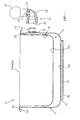
- the vessel according to the invention comprises an outer first body 13 and an inner second body 15.
- Said bodies 13, 15 are cylindrical and have a closed bottom 13a, 15a, respectively, and an opening 13b, 15b, respectively, on the opposite base.
- a hollow space 17 is defined between said bodies 13, 15 and extends, preferably without interruptions, along the bottom and the walls of vessel 11.
- outer body 13 and inner body 15 have circumferential edges 13c, 15c extending radially outwards from vessel 11 and partially overlapping each other in order to close hollow space 17.
- Outer body 13 laterally has a hole 19 for a pressure adjusting device 21 inside hollow space 17, said device being shown partially disassembled in the Figure.
- Device 21 substantially comprises a bushing 23, an L-shaped connector 25 and a valve 27.
- Bushing 23 preferably cylindrical and made of brass, has a threaded portion 29 for screwing and securing bushing 23 into hole 19 of outer body 13.
- a layer of adhesive material is applied between threaded portion 29 and the edge defining hole 19.
- L-shaped connector 25, which substantially acts as a support for valve 27, includes a cylindrical seat 31 where the body of bushing 23 is received, upon application of a layer of adhesive in order to ensure the required tightness.
- connection of device 21 is quick and simple, and connector 25 can be firmly secured in the correct position so that valve 27 is correctly oriented upwards.
- bushing 23 can be tightly screwed into hole 19, since the final orientation of the bushing is of no relevance in order to ensure the correct arrangement of valve 27.
- connector 25 is secured to bushing 23 by gluing thanks to the layer of adhesive material, thereby allowing the desired arrangement of connector 25 ensuring the correct orientation of valve 27.
- Valve 27 which may be of a known type comprising a mass sliding in an axial chamber when raised by the steam pressure, is secured to connector 25 by screwing threaded portion 33 into the corresponding seat 35 provided in connector 25.
- valve 27 can be easily manually removed by the user when the water level inside hollow space 17 is to be restored, and can be as easily mounted again before vessel 11 is used for cooking food.
- bottom 13a of outer body 13 has associated therewith an aluminium disc 37.
- said aluminium disc 37 is enclosed in a capsule 39 defining the bearing surface of vessel 11.
- Aluminium disc 37 has a thickness in the range 3 to 10 mm, preferably of about 6 mm.
- Capsule 39 is preferably secured to bottom 13a of outer body 13 by welding along perimeter 41 between the peripheral edge of capsule 39 and the outer surface of bottom 13a of outer body 13.
- capsule 39 is made of steel with high ferrite content, for instance AISI 430 steel, so that vessel 11 can be used also in conjunction with induction cooking devices.
- vessels preferably with flat bottom, made of steel with high ferrite content, such as for instance AISI 410 (C ⁇ 0.15) and AISI 430 (C ⁇ 0.12) steel.
- disc 37 of aluminium i.e. of a cheap and light material, interposed between capsule 39 and body 13 ensures an optimum heat conduction between capsule 39 and body 13 and a uniform and perfectly controllable cooking.
- vessels could be envisaged in which a capsule 39 of a material with high ferrite content is still provided, but the aluminium disc is lacking or is made of a different material.
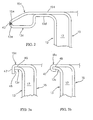
- FIG. 2 the joining area of edges 13c, 15c is shown in greater detail, with reference to a first embodiment of the invention.
- edges 13c, 15c partially overlap each other along a corresponding portion 13d, 15d and are tapered towards the outside of vessel 11, so as to define a joining area 13e, 15e, respectively, where the weld material will be deposited, preferably according to the TIG (Tungsten Inert Gas) technology, thereby defining welding bead 43.
- TIG Tungsten Inert Gas
- joining areas 13e, 15e define a corresponding circumferential groove that is filled by TIG welding bead 43, thereby forming a corresponding blunt and smooth peripheral edge, perfectly connected to joining areas 13e, 15e.
- FIGs. 3a and 3b a second embodiment of the invention is shown, where edges 13c, 15c are joined together by crimping preceded by gluing.
- Fig. 3a shows the configuration taken by edges 13c, 15c after cold forming in a suitable die in order to define the corresponding edges 13c, 15c closing hollow space 17.
- Edge 15c of inner body 15 is bent to an L shape and it defines a corresponding internal abutment surface 45 for edge 13c of the outer body.
- portion 47 of edge 15c is folded under edge 15c so as to obtain the crimping of the latter.
- a layer of adhesive denoted 49 in the Figure, is provided between the adjoining surfaces of edges 13c, 15c.
- Manufacturing of the vessel according to the invention is substantially carried out in the following manner.
- Outer and inner bodies 13, 15 are preferably made by cold forming sheet steel suitable for use with food, for instance of the AISI 304 type with a thickness of about 1.0 mm and preferably below 1.0 mm.
- a side hole 19 for pressure adjusting device 21 is then pierced in outer body 13.
- outer and inner bodies 13, 15 are joined together along the respective top edges 13c, 15c by TIG welding.
- joining of edges 13c, 15c takes place by crimping, upon deposition of adhesive along the edges of the contacting surfaces.
- Vessel 11 is then subjected to a polishing step.
- Bushing 23 is screwed into hole 19 provided in outer body 13 of vessel 11, upon deposition of an adhesive that, once hardened, locks bushing 23 in hole 19 and ensures the required tightness with the edge of said hole 19.
- connector 25 is secured to bushing 23, also in this case upon application of an adhesive.
- steam adjusting valve 27 is mounted, preferably screwed, into connector 25.
- the adhesive used for gluing circumferential edges 13c, 15c of bushing 23 and connector 25 is preferably an adhesive suitable for gluing threaded parts and cylindrical components, resistant to high temperatures and resistant to corrosion, for instance an anaerobic adhesive with quick hardening and high mechanical resistance.
- the vessel according to the invention can be manufactured in any size and even with non-circular cross-sectional shape, e.g. a square, oval ... shape.
Landscapes
- Engineering & Computer Science (AREA)
- Food Science & Technology (AREA)
- Manufacturing & Machinery (AREA)
- Cookers (AREA)
- Package Specialized In Special Use (AREA)
- General Preparation And Processing Of Foods (AREA)
Claims (15)
- Verfahren zur Herstellung eines Nahrungsmittelgargefäßes (11), wobei dieses Gefäß einen ersten, äußeren Körper (13) sowie einen zweiten, inneren Körper (15), die beide einen geschlossenen Boden (13a, 15a) und eine entsprechende Öffnung (13b, 15b) an der gegenüberliegenden Basis aufweisen und dazwischen einen Hohlraum (17) bilden, der einer eine Hülse (23), ein L-förmiges Verbindungselement (25) und ein Dampfregelungsventil (27) aufweisenden Druckregelungsvorrichtung (21) zugeordnet ist, wobei dieser erste und zweite Körper (13, 15) entsprechende umlaufende Ränder (13c, 15c) haben, die sich mindestens teilweise überlappen, um den Hohlraum (17) zu schließen, wobei das Verfahren dadurch gekennzeichnet ist, dass das Anbringen der Druckregelungsvorrichtung (21) die folgenden Schritte umfasst:- die Hülse (23) in eine in dem äußeren Körper (13) des Gefäßes (11) vorgesehene Bohrung (19) einzuschrauben, unter Aufbringung einer Klebstoffschicht;- diesen Klebstoff aushärten zu lassen, sodass die Hülse (23) in der Bohrung (19) geklemmt wird und die gewünschte Dichtigkeit gewährleistet wird;- ein L-förmiges Verbindungselement (25) an der Hülse (23) zu befestigen, unter Aufbringung einer Klebstoffschicht;- diesen Klebstoff aushärten zu lassen, sodass dieses Verbindungselement (25) an dieser Hülse (23) befestigt wird;- ein Dampfregelungsventil (27) an dem Verbindungselement (25) anzubringen.
- Verfahren nach Anspruch 1, wobei das Ventil (27) einen Gewindeabschnitt (33) aufweist und entfernbar an dem Verbindungselement (25) befestigt wird, indem dieser Gewindeabschnitt in eine in dem Verbindungselement (25) vorgesehene entsprechende Aufnahme (35) eingeschraubt wird.
- Verfahren nach Anspruch 1 oder 2, wobei diese umlaufenden Ränder (13c, 15c) durch Schweißen oder Falzen miteinander verbunden sind, um den Hohlraum (17) zu schließen.
- Verfahren nach Anspruch 3, wobei vor diesem Falzen ein Schritt des Aufbringens einer Klebstoffschicht (49) durchgeführt wird.
- Verfahren nach Anspruch 1, umfassend das Bohren einer Bohrung in den äußeren Körper (13), um die Druckregelungsvorrichtung (21) zu befestigen.
- Verfahren nach Anspruch 1, umfassend das Anbringen einer Kapsel (39) aus einem Material mit hohem Ferritinhalt auf die Außenfläche des Bodens (13a) des äußeren Körpers (13).
- Verfahren nach Anspruch 6, wobei dieses Material mit hohem Ferritinhalt Stahl AISI 410 oder Stahl AISI 430 ist.
- Verfahren nach Anspruch 6 oder 7, wobei diese Kapsel (39) durch Schweißen angebracht wird.
- Verfahren nach Anspruch 6 oder 7 oder 8, umfassend das Einschließen einer Aluminiumscheibe (37) in diese Kapsel (39).
- Verfahren nach Anspruch 9, wobei diese Aluminiumscheibe (37) 3 bis 10 mm dick ist.
- Verfahren nach Anspruch 10, wobei diese Aluminiumscheibe (37) ungefähr 6 mm dick ist.
- Verfahren nach einem der vorangehenden Ansprüche, wobei dieser Klebstoff ein zum Kleben von Gewindeteilen und zylindrischen Bestandteilen geeigneter Klebstoff ist, der hochtemperaturbeständig sowie korrosionsbeständig ist.
- Verfahren nach Anspruch 12, wobei dieser Klebstoff ein schnellhärtender anaerobischer Klebstoff ist.
- Nahrungsmittelgargefäß (11) hergestellt durch das Verfahren nach einem der Ansprüche 1 bis 13.
- Gefäß nach Anspruch 14, wobei dieses Gefäß ein Nahrungsmittelgargefäß ist, das das sogenannte Prinzip der indirekten Dämpfung mit automatischer Temperatursteuerung anwendet.
Applications Claiming Priority (2)
| Application Number | Priority Date | Filing Date | Title |
|---|---|---|---|
| ITTO20070641 ITTO20070641A1 (it) | 2007-09-11 | 2007-09-11 | Metodo per la realizzazione di un recipiente per la cottura di cibi e recipiente cosi ottenuto. |
| PCT/IB2008/053559 WO2009034502A2 (en) | 2007-09-11 | 2008-09-03 | A method of manufacturing a vessel for cooking food, and a vessel thus obtained |
Publications (2)
| Publication Number | Publication Date |
|---|---|
| EP2200486A2 EP2200486A2 (de) | 2010-06-30 |
| EP2200486B1 true EP2200486B1 (de) | 2014-01-08 |
Family
ID=40316597
Family Applications (1)
| Application Number | Title | Priority Date | Filing Date |
|---|---|---|---|
| EP08807512.2A Active EP2200486B1 (de) | 2007-09-11 | 2008-09-03 | Verfahren zur herstellung eines nahrungsmittelgargefässes und damit erhaltenes gargefäss |
Country Status (3)
| Country | Link |
|---|---|
| EP (1) | EP2200486B1 (de) |
| IT (1) | ITTO20070641A1 (de) |
| WO (1) | WO2009034502A2 (de) |
Families Citing this family (1)
| Publication number | Priority date | Publication date | Assignee | Title |
|---|---|---|---|---|
| KR101533598B1 (ko) * | 2013-12-05 | 2015-07-03 | (주)삼미통상 | 안정성과 열효율이 향상된 이중조리용기 |
Citations (1)
| Publication number | Priority date | Publication date | Assignee | Title |
|---|---|---|---|---|
| ITTO990096U1 (it) * | 1999-05-21 | 2000-11-21 | Longhi Giuliano | Gruppo generatore di energia elettrica per la ricarica di accumulatoriin particolare per camper o simili |
Family Cites Families (5)
| Publication number | Priority date | Publication date | Assignee | Title |
|---|---|---|---|---|
| CH167463A (de) * | 1932-10-10 | 1934-02-28 | Gut Schmid Heinrich | Kochtopf. |
| CH422183A (de) * | 1964-03-24 | 1966-10-15 | Salvis Ag Fabrik Elektr Appara | Entlüftungsventil an einem mit Dampf beheizten Elektro-Kochkessel |
| US5228384A (en) * | 1992-11-30 | 1993-07-20 | Kolosowski Jadwiga M | Double boiler container |
| KR200199996Y1 (ko) * | 2000-05-09 | 2000-10-16 | 주식회사광해물산 | 압력조절수단을 갖는 오일남비 |
| KR20030044585A (ko) * | 2001-11-30 | 2003-06-09 | 박종도 | 이중냄비의 에어포켓 내부 압력조절장치 |
-
2007
- 2007-09-11 IT ITTO20070641 patent/ITTO20070641A1/it unknown
-
2008
- 2008-09-03 EP EP08807512.2A patent/EP2200486B1/de active Active
- 2008-09-03 WO PCT/IB2008/053559 patent/WO2009034502A2/en not_active Ceased
Patent Citations (1)
| Publication number | Priority date | Publication date | Assignee | Title |
|---|---|---|---|---|
| ITTO990096U1 (it) * | 1999-05-21 | 2000-11-21 | Longhi Giuliano | Gruppo generatore di energia elettrica per la ricarica di accumulatoriin particolare per camper o simili |
Also Published As
| Publication number | Publication date |
|---|---|
| ITTO20070641A1 (it) | 2009-03-12 |
| WO2009034502A3 (en) | 2009-06-11 |
| EP2200486A2 (de) | 2010-06-30 |
| WO2009034502A2 (en) | 2009-03-19 |
Similar Documents
| Publication | Publication Date | Title |
|---|---|---|
| US6320166B1 (en) | Double layered cooking apparatus | |
| US7980171B2 (en) | Vacuum cooking or warming appliance | |
| US20140326733A1 (en) | Eco green cookware | |
| JP5870243B2 (ja) | 加熱調理器 | |
| MY153598A (en) | Infrared radiation cooker | |
| US4397874A (en) | Popcorn popping | |
| EP2200486B1 (de) | Verfahren zur herstellung eines nahrungsmittelgargefässes und damit erhaltenes gargefäss | |
| EP2197327B1 (de) | Verfahren zur herstellung eines nahrungsmittelgargefässes und damit erhaltenes gargefäss | |
| JP2004248901A (ja) | 炊飯器 | |
| EP2207458A2 (de) | Gefäss zum garen von nahrungsmitteln | |
| JPWO2002001991A1 (ja) | 調理用容器 | |
| KR20100011345A (ko) | 구이판 및 그 제조방법 | |
| KR20100044402A (ko) | 주방용기 및 그 제조방법 | |
| KR200402191Y1 (ko) | 주방용 가열용기 | |
| KR200253634Y1 (ko) | 3중 바닥 주방기구 | |
| KR200299303Y1 (ko) | 조리용 가열용기 | |
| KR200179561Y1 (ko) | 이중 구이판 | |
| CN201139414Y (zh) | 真空锅 | |
| CN216439002U (zh) | 一种火力可控的火锅锅炉 | |
| KR20110089010A (ko) | 조리기구 및 그 제조방법 | |
| CN109875386A (zh) | 米饭口感均衡的电饭煲 | |
| WO1999047035A1 (en) | Stored heat cooker | |
| KR200349074Y1 (ko) | 냄비 | |
| KR20240003968A (ko) | 열변형 방지 조리용기 | |
| FR2635960A1 (fr) | Marmite dietetique multifonctions |
Legal Events
| Date | Code | Title | Description |
|---|---|---|---|
| PUAI | Public reference made under article 153(3) epc to a published international application that has entered the european phase |
Free format text: ORIGINAL CODE: 0009012 |
|
| 17P | Request for examination filed |
Effective date: 20100407 |
|
| AK | Designated contracting states |
Kind code of ref document: A2 Designated state(s): AT BE BG CH CY CZ DE DK EE ES FI FR GB GR HR HU IE IS IT LI LT LU LV MC MT NL NO PL PT RO SE SI SK TR |
|
| AX | Request for extension of the european patent |
Extension state: AL BA MK RS |
|
| 17Q | First examination report despatched |
Effective date: 20110705 |
|
| DAX | Request for extension of the european patent (deleted) | ||
| GRAJ | Information related to disapproval of communication of intention to grant by the applicant or resumption of examination proceedings by the epo deleted |
Free format text: ORIGINAL CODE: EPIDOSDIGR1 |
|
| GRAP | Despatch of communication of intention to grant a patent |
Free format text: ORIGINAL CODE: EPIDOSNIGR1 |
|
| INTG | Intention to grant announced |
Effective date: 20130404 |
|
| GRAS | Grant fee paid |
Free format text: ORIGINAL CODE: EPIDOSNIGR3 |
|
| GRAA | (expected) grant |
Free format text: ORIGINAL CODE: 0009210 |
|
| AK | Designated contracting states |
Kind code of ref document: B1 Designated state(s): AT BE BG CH CY CZ DE DK EE ES FI FR GB GR HR HU IE IS IT LI LT LU LV MC MT NL NO PL PT RO SE SI SK TR |
|
| REG | Reference to a national code |
Ref country code: GB Ref legal event code: FG4D |
|
| REG | Reference to a national code |
Ref country code: CH Ref legal event code: EP |
|
| REG | Reference to a national code |
Ref country code: IE Ref legal event code: FG4D |
|
| REG | Reference to a national code |
Ref country code: AT Ref legal event code: REF Ref document number: 648117 Country of ref document: AT Kind code of ref document: T Effective date: 20140215 |
|
| REG | Reference to a national code |
Ref country code: DE Ref legal event code: R096 Ref document number: 602008029818 Country of ref document: DE Effective date: 20140220 |
|
| REG | Reference to a national code |
Ref country code: AT Ref legal event code: MK05 Ref document number: 648117 Country of ref document: AT Kind code of ref document: T Effective date: 20140108 |
|
| REG | Reference to a national code |
Ref country code: NL Ref legal event code: VDEP Effective date: 20140108 |
|
| REG | Reference to a national code |
Ref country code: LT Ref legal event code: MG4D |
|
| RAP2 | Party data changed (patent owner data changed or rights of a patent transferred) |
Owner name: FOGACCI GROUP SRL |
|
| PG25 | Lapsed in a contracting state [announced via postgrant information from national office to epo] |
Ref country code: NO Free format text: LAPSE BECAUSE OF FAILURE TO SUBMIT A TRANSLATION OF THE DESCRIPTION OR TO PAY THE FEE WITHIN THE PRESCRIBED TIME-LIMIT Effective date: 20140408 Ref country code: LT Free format text: LAPSE BECAUSE OF FAILURE TO SUBMIT A TRANSLATION OF THE DESCRIPTION OR TO PAY THE FEE WITHIN THE PRESCRIBED TIME-LIMIT Effective date: 20140108 Ref country code: IS Free format text: LAPSE BECAUSE OF FAILURE TO SUBMIT A TRANSLATION OF THE DESCRIPTION OR TO PAY THE FEE WITHIN THE PRESCRIBED TIME-LIMIT Effective date: 20140508 |
|
| PG25 | Lapsed in a contracting state [announced via postgrant information from national office to epo] |
Ref country code: PT Free format text: LAPSE BECAUSE OF FAILURE TO SUBMIT A TRANSLATION OF THE DESCRIPTION OR TO PAY THE FEE WITHIN THE PRESCRIBED TIME-LIMIT Effective date: 20140508 Ref country code: SE Free format text: LAPSE BECAUSE OF FAILURE TO SUBMIT A TRANSLATION OF THE DESCRIPTION OR TO PAY THE FEE WITHIN THE PRESCRIBED TIME-LIMIT Effective date: 20140108 Ref country code: AT Free format text: LAPSE BECAUSE OF FAILURE TO SUBMIT A TRANSLATION OF THE DESCRIPTION OR TO PAY THE FEE WITHIN THE PRESCRIBED TIME-LIMIT Effective date: 20140108 Ref country code: CY Free format text: LAPSE BECAUSE OF FAILURE TO SUBMIT A TRANSLATION OF THE DESCRIPTION OR TO PAY THE FEE WITHIN THE PRESCRIBED TIME-LIMIT Effective date: 20140108 Ref country code: FI Free format text: LAPSE BECAUSE OF FAILURE TO SUBMIT A TRANSLATION OF THE DESCRIPTION OR TO PAY THE FEE WITHIN THE PRESCRIBED TIME-LIMIT Effective date: 20140108 Ref country code: ES Free format text: LAPSE BECAUSE OF FAILURE TO SUBMIT A TRANSLATION OF THE DESCRIPTION OR TO PAY THE FEE WITHIN THE PRESCRIBED TIME-LIMIT Effective date: 20140108 Ref country code: NL Free format text: LAPSE BECAUSE OF FAILURE TO SUBMIT A TRANSLATION OF THE DESCRIPTION OR TO PAY THE FEE WITHIN THE PRESCRIBED TIME-LIMIT Effective date: 20140108 |
|
| PG25 | Lapsed in a contracting state [announced via postgrant information from national office to epo] |
Ref country code: LV Free format text: LAPSE BECAUSE OF FAILURE TO SUBMIT A TRANSLATION OF THE DESCRIPTION OR TO PAY THE FEE WITHIN THE PRESCRIBED TIME-LIMIT Effective date: 20140108 Ref country code: HR Free format text: LAPSE BECAUSE OF FAILURE TO SUBMIT A TRANSLATION OF THE DESCRIPTION OR TO PAY THE FEE WITHIN THE PRESCRIBED TIME-LIMIT Effective date: 20140108 Ref country code: BE Free format text: LAPSE BECAUSE OF FAILURE TO SUBMIT A TRANSLATION OF THE DESCRIPTION OR TO PAY THE FEE WITHIN THE PRESCRIBED TIME-LIMIT Effective date: 20140108 |
|
| REG | Reference to a national code |
Ref country code: DE Ref legal event code: R097 Ref document number: 602008029818 Country of ref document: DE |
|
| PG25 | Lapsed in a contracting state [announced via postgrant information from national office to epo] |
Ref country code: EE Free format text: LAPSE BECAUSE OF FAILURE TO SUBMIT A TRANSLATION OF THE DESCRIPTION OR TO PAY THE FEE WITHIN THE PRESCRIBED TIME-LIMIT Effective date: 20140108 Ref country code: RO Free format text: LAPSE BECAUSE OF FAILURE TO SUBMIT A TRANSLATION OF THE DESCRIPTION OR TO PAY THE FEE WITHIN THE PRESCRIBED TIME-LIMIT Effective date: 20140108 Ref country code: CZ Free format text: LAPSE BECAUSE OF FAILURE TO SUBMIT A TRANSLATION OF THE DESCRIPTION OR TO PAY THE FEE WITHIN THE PRESCRIBED TIME-LIMIT Effective date: 20140108 Ref country code: DK Free format text: LAPSE BECAUSE OF FAILURE TO SUBMIT A TRANSLATION OF THE DESCRIPTION OR TO PAY THE FEE WITHIN THE PRESCRIBED TIME-LIMIT Effective date: 20140108 |
|
| PLBE | No opposition filed within time limit |
Free format text: ORIGINAL CODE: 0009261 |
|
| STAA | Information on the status of an ep patent application or granted ep patent |
Free format text: STATUS: NO OPPOSITION FILED WITHIN TIME LIMIT |
|
| PG25 | Lapsed in a contracting state [announced via postgrant information from national office to epo] |
Ref country code: SK Free format text: LAPSE BECAUSE OF FAILURE TO SUBMIT A TRANSLATION OF THE DESCRIPTION OR TO PAY THE FEE WITHIN THE PRESCRIBED TIME-LIMIT Effective date: 20140108 Ref country code: PL Free format text: LAPSE BECAUSE OF FAILURE TO SUBMIT A TRANSLATION OF THE DESCRIPTION OR TO PAY THE FEE WITHIN THE PRESCRIBED TIME-LIMIT Effective date: 20140108 |
|
| 26N | No opposition filed |
Effective date: 20141009 |
|
| REG | Reference to a national code |
Ref country code: DE Ref legal event code: R097 Ref document number: 602008029818 Country of ref document: DE Effective date: 20141009 |
|
| PG25 | Lapsed in a contracting state [announced via postgrant information from national office to epo] |
Ref country code: MC Free format text: LAPSE BECAUSE OF FAILURE TO SUBMIT A TRANSLATION OF THE DESCRIPTION OR TO PAY THE FEE WITHIN THE PRESCRIBED TIME-LIMIT Effective date: 20140108 Ref country code: LU Free format text: LAPSE BECAUSE OF FAILURE TO SUBMIT A TRANSLATION OF THE DESCRIPTION OR TO PAY THE FEE WITHIN THE PRESCRIBED TIME-LIMIT Effective date: 20140903 |
|
| REG | Reference to a national code |
Ref country code: CH Ref legal event code: PL |
|
| GBPC | Gb: european patent ceased through non-payment of renewal fee |
Effective date: 20140903 |
|
| PG25 | Lapsed in a contracting state [announced via postgrant information from national office to epo] |
Ref country code: SI Free format text: LAPSE BECAUSE OF FAILURE TO SUBMIT A TRANSLATION OF THE DESCRIPTION OR TO PAY THE FEE WITHIN THE PRESCRIBED TIME-LIMIT Effective date: 20140108 |
|
| REG | Reference to a national code |
Ref country code: IE Ref legal event code: MM4A |
|
| PG25 | Lapsed in a contracting state [announced via postgrant information from national office to epo] |
Ref country code: GB Free format text: LAPSE BECAUSE OF NON-PAYMENT OF DUE FEES Effective date: 20140903 Ref country code: LI Free format text: LAPSE BECAUSE OF NON-PAYMENT OF DUE FEES Effective date: 20140930 Ref country code: CH Free format text: LAPSE BECAUSE OF NON-PAYMENT OF DUE FEES Effective date: 20140930 |
|
| PG25 | Lapsed in a contracting state [announced via postgrant information from national office to epo] |
Ref country code: IE Free format text: LAPSE BECAUSE OF NON-PAYMENT OF DUE FEES Effective date: 20140903 |
|
| REG | Reference to a national code |
Ref country code: FR Ref legal event code: PLFP Year of fee payment: 8 |
|
| PG25 | Lapsed in a contracting state [announced via postgrant information from national office to epo] |
Ref country code: BG Free format text: LAPSE BECAUSE OF FAILURE TO SUBMIT A TRANSLATION OF THE DESCRIPTION OR TO PAY THE FEE WITHIN THE PRESCRIBED TIME-LIMIT Effective date: 20140108 |
|
| PG25 | Lapsed in a contracting state [announced via postgrant information from national office to epo] |
Ref country code: IT Free format text: LAPSE BECAUSE OF FAILURE TO SUBMIT A TRANSLATION OF THE DESCRIPTION OR TO PAY THE FEE WITHIN THE PRESCRIBED TIME-LIMIT Effective date: 20140108 Ref country code: MT Free format text: LAPSE BECAUSE OF FAILURE TO SUBMIT A TRANSLATION OF THE DESCRIPTION OR TO PAY THE FEE WITHIN THE PRESCRIBED TIME-LIMIT Effective date: 20140108 Ref country code: GR Free format text: LAPSE BECAUSE OF FAILURE TO SUBMIT A TRANSLATION OF THE DESCRIPTION OR TO PAY THE FEE WITHIN THE PRESCRIBED TIME-LIMIT Effective date: 20140409 |
|
| PG25 | Lapsed in a contracting state [announced via postgrant information from national office to epo] |
Ref country code: HU Free format text: LAPSE BECAUSE OF FAILURE TO SUBMIT A TRANSLATION OF THE DESCRIPTION OR TO PAY THE FEE WITHIN THE PRESCRIBED TIME-LIMIT; INVALID AB INITIO Effective date: 20080903 Ref country code: TR Free format text: LAPSE BECAUSE OF FAILURE TO SUBMIT A TRANSLATION OF THE DESCRIPTION OR TO PAY THE FEE WITHIN THE PRESCRIBED TIME-LIMIT Effective date: 20140108 |
|
| REG | Reference to a national code |
Ref country code: FR Ref legal event code: PLFP Year of fee payment: 9 |
|
| REG | Reference to a national code |
Ref country code: FR Ref legal event code: PLFP Year of fee payment: 10 |
|
| REG | Reference to a national code |
Ref country code: FR Ref legal event code: PLFP Year of fee payment: 11 |
|
| REG | Reference to a national code |
Ref country code: DE Ref legal event code: R082 Ref document number: 602008029818 Country of ref document: DE Representative=s name: FRANKE & PARTNER PATENT- UND RECHTSANWALTSKANZ, DE |
|
| PGFP | Annual fee paid to national office [announced via postgrant information from national office to epo] |
Ref country code: DE Payment date: 20250804 Year of fee payment: 18 |
|
| PGFP | Annual fee paid to national office [announced via postgrant information from national office to epo] |
Ref country code: FR Payment date: 20250813 Year of fee payment: 18 |