EP2199850B1 - Liquid crystal display with pixel pairs using a common gate line - Google Patents
Liquid crystal display with pixel pairs using a common gate line Download PDFInfo
- Publication number
- EP2199850B1 EP2199850B1 EP09014970.9A EP09014970A EP2199850B1 EP 2199850 B1 EP2199850 B1 EP 2199850B1 EP 09014970 A EP09014970 A EP 09014970A EP 2199850 B1 EP2199850 B1 EP 2199850B1
- Authority
- EP
- European Patent Office
- Prior art keywords
- data line
- switching element
- pixel
- common gate
- data
- Prior art date
- Legal status (The legal status is an assumption and is not a legal conclusion. Google has not performed a legal analysis and makes no representation as to the accuracy of the status listed.)
- Not-in-force
Links
Images


Classifications
-
- G—PHYSICS
- G09—EDUCATION; CRYPTOGRAPHY; DISPLAY; ADVERTISING; SEALS
- G09G—ARRANGEMENTS OR CIRCUITS FOR CONTROL OF INDICATING DEVICES USING STATIC MEANS TO PRESENT VARIABLE INFORMATION
- G09G3/00—Control arrangements or circuits, of interest only in connection with visual indicators other than cathode-ray tubes
- G09G3/20—Control arrangements or circuits, of interest only in connection with visual indicators other than cathode-ray tubes for presentation of an assembly of a number of characters, e.g. a page, by composing the assembly by combination of individual elements arranged in a matrix no fixed position being assigned to or needed to be assigned to the individual characters or partial characters
- G09G3/34—Control arrangements or circuits, of interest only in connection with visual indicators other than cathode-ray tubes for presentation of an assembly of a number of characters, e.g. a page, by composing the assembly by combination of individual elements arranged in a matrix no fixed position being assigned to or needed to be assigned to the individual characters or partial characters by control of light from an independent source
- G09G3/36—Control arrangements or circuits, of interest only in connection with visual indicators other than cathode-ray tubes for presentation of an assembly of a number of characters, e.g. a page, by composing the assembly by combination of individual elements arranged in a matrix no fixed position being assigned to or needed to be assigned to the individual characters or partial characters by control of light from an independent source using liquid crystals
-
- G—PHYSICS
- G02—OPTICS
- G02F—OPTICAL DEVICES OR ARRANGEMENTS FOR THE CONTROL OF LIGHT BY MODIFICATION OF THE OPTICAL PROPERTIES OF THE MEDIA OF THE ELEMENTS INVOLVED THEREIN; NON-LINEAR OPTICS; FREQUENCY-CHANGING OF LIGHT; OPTICAL LOGIC ELEMENTS; OPTICAL ANALOGUE/DIGITAL CONVERTERS
- G02F1/00—Devices or arrangements for the control of the intensity, colour, phase, polarisation or direction of light arriving from an independent light source, e.g. switching, gating or modulating; Non-linear optics
- G02F1/01—Devices or arrangements for the control of the intensity, colour, phase, polarisation or direction of light arriving from an independent light source, e.g. switching, gating or modulating; Non-linear optics for the control of the intensity, phase, polarisation or colour
- G02F1/13—Devices or arrangements for the control of the intensity, colour, phase, polarisation or direction of light arriving from an independent light source, e.g. switching, gating or modulating; Non-linear optics for the control of the intensity, phase, polarisation or colour based on liquid crystals, e.g. single liquid crystal display cells
- G02F1/133—Constructional arrangements; Operation of liquid crystal cells; Circuit arrangements
- G02F1/136—Liquid crystal cells structurally associated with a semi-conducting layer or substrate, e.g. cells forming part of an integrated circuit
- G02F1/1362—Active matrix addressed cells
- G02F1/136286—Wiring, e.g. gate line, drain line
-
- G—PHYSICS
- G02—OPTICS
- G02F—OPTICAL DEVICES OR ARRANGEMENTS FOR THE CONTROL OF LIGHT BY MODIFICATION OF THE OPTICAL PROPERTIES OF THE MEDIA OF THE ELEMENTS INVOLVED THEREIN; NON-LINEAR OPTICS; FREQUENCY-CHANGING OF LIGHT; OPTICAL LOGIC ELEMENTS; OPTICAL ANALOGUE/DIGITAL CONVERTERS
- G02F1/00—Devices or arrangements for the control of the intensity, colour, phase, polarisation or direction of light arriving from an independent light source, e.g. switching, gating or modulating; Non-linear optics
- G02F1/01—Devices or arrangements for the control of the intensity, colour, phase, polarisation or direction of light arriving from an independent light source, e.g. switching, gating or modulating; Non-linear optics for the control of the intensity, phase, polarisation or colour
- G02F1/13—Devices or arrangements for the control of the intensity, colour, phase, polarisation or direction of light arriving from an independent light source, e.g. switching, gating or modulating; Non-linear optics for the control of the intensity, phase, polarisation or colour based on liquid crystals, e.g. single liquid crystal display cells
- G02F1/133—Constructional arrangements; Operation of liquid crystal cells; Circuit arrangements
-
- G—PHYSICS
- G09—EDUCATION; CRYPTOGRAPHY; DISPLAY; ADVERTISING; SEALS
- G09G—ARRANGEMENTS OR CIRCUITS FOR CONTROL OF INDICATING DEVICES USING STATIC MEANS TO PRESENT VARIABLE INFORMATION
- G09G3/00—Control arrangements or circuits, of interest only in connection with visual indicators other than cathode-ray tubes
- G09G3/20—Control arrangements or circuits, of interest only in connection with visual indicators other than cathode-ray tubes for presentation of an assembly of a number of characters, e.g. a page, by composing the assembly by combination of individual elements arranged in a matrix no fixed position being assigned to or needed to be assigned to the individual characters or partial characters
- G09G3/34—Control arrangements or circuits, of interest only in connection with visual indicators other than cathode-ray tubes for presentation of an assembly of a number of characters, e.g. a page, by composing the assembly by combination of individual elements arranged in a matrix no fixed position being assigned to or needed to be assigned to the individual characters or partial characters by control of light from an independent source
- G09G3/36—Control arrangements or circuits, of interest only in connection with visual indicators other than cathode-ray tubes for presentation of an assembly of a number of characters, e.g. a page, by composing the assembly by combination of individual elements arranged in a matrix no fixed position being assigned to or needed to be assigned to the individual characters or partial characters by control of light from an independent source using liquid crystals
- G09G3/3611—Control of matrices with row and column drivers
- G09G3/3648—Control of matrices with row and column drivers using an active matrix
-
- G—PHYSICS
- G09—EDUCATION; CRYPTOGRAPHY; DISPLAY; ADVERTISING; SEALS
- G09G—ARRANGEMENTS OR CIRCUITS FOR CONTROL OF INDICATING DEVICES USING STATIC MEANS TO PRESENT VARIABLE INFORMATION
- G09G2300/00—Aspects of the constitution of display devices
- G09G2300/04—Structural and physical details of display devices
- G09G2300/0421—Structural details of the set of electrodes
- G09G2300/0426—Layout of electrodes and connections
-
- G—PHYSICS
- G09—EDUCATION; CRYPTOGRAPHY; DISPLAY; ADVERTISING; SEALS
- G09G—ARRANGEMENTS OR CIRCUITS FOR CONTROL OF INDICATING DEVICES USING STATIC MEANS TO PRESENT VARIABLE INFORMATION
- G09G2310/00—Command of the display device
- G09G2310/02—Addressing, scanning or driving the display screen or processing steps related thereto
- G09G2310/0202—Addressing of scan or signal lines
- G09G2310/0205—Simultaneous scanning of several lines in flat panels
-
- G—PHYSICS
- G09—EDUCATION; CRYPTOGRAPHY; DISPLAY; ADVERTISING; SEALS
- G09G—ARRANGEMENTS OR CIRCUITS FOR CONTROL OF INDICATING DEVICES USING STATIC MEANS TO PRESENT VARIABLE INFORMATION
- G09G3/00—Control arrangements or circuits, of interest only in connection with visual indicators other than cathode-ray tubes
- G09G3/20—Control arrangements or circuits, of interest only in connection with visual indicators other than cathode-ray tubes for presentation of an assembly of a number of characters, e.g. a page, by composing the assembly by combination of individual elements arranged in a matrix no fixed position being assigned to or needed to be assigned to the individual characters or partial characters
- G09G3/34—Control arrangements or circuits, of interest only in connection with visual indicators other than cathode-ray tubes for presentation of an assembly of a number of characters, e.g. a page, by composing the assembly by combination of individual elements arranged in a matrix no fixed position being assigned to or needed to be assigned to the individual characters or partial characters by control of light from an independent source
- G09G3/36—Control arrangements or circuits, of interest only in connection with visual indicators other than cathode-ray tubes for presentation of an assembly of a number of characters, e.g. a page, by composing the assembly by combination of individual elements arranged in a matrix no fixed position being assigned to or needed to be assigned to the individual characters or partial characters by control of light from an independent source using liquid crystals
- G09G3/3611—Control of matrices with row and column drivers
- G09G3/3614—Control of polarity reversal in general
Definitions
- the present disclosure relates to a liquid crystal display, and more particularly, to liquid crystal display pixel arrays.
- a liquid crystal display is a widely used flat panel display (FPD). It is composed of two display panels on which are formed field generating electrodes, such as pixel electrodes and a common electrode. A liquid crystal layer is interposed between the two display panels. A voltage is applied to the field generating electrodes to generate an electric field in the liquid crystal layer. The orientation of liquid crystal molecules of the liquid crystal layer is determined and the polarization of incident light is controlled through the generated electric field to display an image.
- a thin film transistor (TFT) array includes gate lines for transmitting scanning signals and data lines for transmitting data lines crossing each other to define pixels.
- Each pixel of the array includes a TFT connected to a gate line and a data line, and a pixel electrode connected to the TFT.
- a pixel array is formed on the TFT array using a plurality of pixels, each including the TFT.
- a data driver of an LCD is typically a high-priced, highly functional device as compared to a gate driver, it becomes difficult to mount the data driver directly on a glass substrate using amorphous silicon TFTs.
- the manufacturing cost sharply increases. Therefore, in order to reduce the manufacturing cost, it becomes helpful to reduce the number of channels. It also becomes helpful for the LCDs to have pixel arrays which provide sufficient charging time for the gate driver circuits.
- Document US 2007/0008263 A1 is directed to a liquid crystal display including a plurality of pixels arranged in the form of a matrix and having first and second sub-pixels.
- a plurality of gate lines are connected to the first and second sub-pixels to transmit gate signals thereto.
- a plurality of first and second data lines cross the gate lines, and are connected to the first and second sub-pixels to transmit first and second data voltages thereto, respectively.
- a data driver outputs the first and second data voltages to the first and second data lines, respectively.
- the first and second data voltages have the same polarity.
- a pixel is divided into two sub-pixels, and different data voltages are separately applied to the two sub-pixels, thereby enhancing visibility.
- Document JP 2006 195436 A is directed to an active matrix display apparatus including an active matrix display panel comprising a plurality of pixels arranged in a matrix in a row direction and a column direction, each pixel being constituted by a plurality of subpixels; and a drive circuit for applying a voltage to each of the subpixels so that a polarity of the voltage is inverted at a predetermined period in each of a row direction and a column direction.
- the plurality of subpixels are arranged in the row direction at a period different from half of the predetermined period of polarity inversion of the voltage in the row direction, thus providing flicker-less color display device even when general driver ICs for dot inversion drive are used.
- An exemplary embodiment of the present invention according to the claims provides an LCD which reduces the number of channels and provides appropriate charging time for gate driver circuits.
- An exemplary embodiment of an LCD according to the claims includes a pixel array having a plurality of pixels in a matrix on a substrate.
- the matrix has at least a first pixel row and a second pixel row adjacent the first pixel row. Both the first pixel row and the second pixel row extend in a first direction.
- a first pixel and a second pixel of the first pixel row are adjacent to each other along the first direction.
- the first pixel and the second pixel respectively include a first switching element and a second switching element.
- a first common gate line extends in a second direction different from the first direction and is commonly connected to the first switching element and to the second switching element.
- a first data line and a second data line extend in the first direction and are connected to the first switching element and to the second switching element, respectively.
- the substrate may have a long side and a short side, the long side being substantially parallel to the first direction, and the short side being substantially parallel to the second direction.
- a length of the first pixel in the second direction may be greater than a length of the first pixel in the first direction.
- the pixel array may alternately display colors of red, green and blue in the first direction and display the same color in the second direction.
- a pair of a first data line and a second data line are in each row of the pixel array.
- Each of the pixels includes a switching element, respectively, and switching elements of a column of pixels in the pixel array may be alternately connected to a first data line of a row and to a second data line in an adjacent row.
- a third data line is further provided on the substrate.
- the first data line, the second data line and the third data line is on the substrate at repeated intervals.
- the second data line and the third data line may be opposed to and substantially parallel to each other.
- the first pixel row may be between the first data line and the second data line.
- the second pixel row may be between the third data line and the first data line.
- a second common gate line is further provided on the substrate.
- the first common gate line and second common gate line is on the substrate at repeated intervals.
- the second common gate line is adjacent to and substantially parallel to the first common gate line.
- the second pixel is between the first common gate line and the second common gate line.
- the pixel array includes six pixels in a 2 ⁇ 3 matrix, the six pixels including the first pixel, the second pixel, a third pixel, a fourth pixel, a fifth pixel and a sixth pixel.
- the first pixel, the second pixel, and the third pixel having a third switching element are in the first pixel row
- the fourth pixel, the fifth pixel and the sixth pixel, respectively including a fourth switching element, a fifth switching element and a sixth switching element, are in the second pixel row.
- the third switching element is connected to the second common gate line and to the second data line.
- the fourth switching element is connected to the first common gate line and to the third data line.
- the fifth switching element is connected to the second common gate line and to the third data line.
- the sixth switching element is connected to the second common gate line and to the first data line.
- a first signal is consecutively applied twice followed by a second signal consecutively applied twice, at repeated intervals.
- the second signal is consecutively applied twice followed by the first signal consecutively applied twice, at repeated intervals.
- the first signal is consecutively applied twice followed by the second signal consecutively applied twice, at repeated intervals.
- the first signal and the second signal are alternately applied to adjacent data lines.
- a third data line is further provided on the substrate.
- the first data line, the second data line and the third data line are on the substrate at repeated intervals.
- the third data line and the second data line are opposed to and substantially parallel to each other.
- the first pixel row is between the second data line and the first data line.
- the second pixel row is between the first data line and the third data line.
- a second common gate line is further provided on the substrate.
- the first common gate line and the second common gate line are on the substrate at repeated intervals.
- the second common gate line is adjacent to and substantially parallel to the first common gate line.
- the second pixel is between the first common gate line and the second common gate lines.
- the pixel array includes 12 pixels in a 2 ⁇ 6 matrix.
- the first pixel row includes the first pixel, the second pixel, a third pixel, a fourth pixel, a fifth pixel and a sixth pixel, respectively including the first switching element, the second switching element, a third switching element, a fourth switching element, and a sixth switching element, along the first direction.
- the second pixel row includes a seventh pixel, an eighth pixel, a ninth pixel, a tenth pixel, an eleventh pixel and a twelfth pixel, respectively including a seventh switching element, an eighth switching element, a ninth switching element, a tenth switching element an eleventh switching element and a twelfth switching element, along the first direction,
- the third switching element is connected to the second common gate line and to the second data line.
- the fourth switching element is connected to a second first common gate line and to the second data line.
- the fifth switching element is connected to a second second common gate line and to the second data line.
- the sixth switching element is connected to the second second common gate line and to the first data line.
- the seventh switching element is connected to the first common gate line and to the third data line.
- the eighth switching element is connected to the second common gate line and to the third data line.
- the ninth switching element is connected to the second common gate line and to the first data line.
- the tenth switching element is connected to a second first common gate line and to the first data line.
- the eleventh switching element is connected to the second first common gate line and to the third data line.
- the twelfth switching element is connected to the second second common gate line and to the third data line.
- the first signal and the second signal are alternately applied to adjacent data lines.
- a third data line is further provided on the substrate.
- the first data line, the second data line and the third data line are on the substrate at repeated intervals.
- the third data line and the first data line are opposed to and substantially parallel to each other.
- the first pixel row is between the first data line and the second data line.
- the second pixel row is between the second data line and the third data line.
- a second common gate line is further provided on the substrate.
- the first common gate line and the second common gate line are on the substrate at repeated intervals.
- the second common gate line is adjacent to and substantially parallel to the first common gate line.
- the second pixel is between the first common gate line and the second common gate line.
- the pixel array includes 12 pixels in a 2 ⁇ 6 matrix.
- the first pixel row includes the first pixel, the second pixel, a third pixel, a fourth pixel, a fifth pixel and a sixth pixel, respectively including the first switching element, the second switching element, a third switching element, a fourth switching element, a fifth switching element and a sixth switching element, along the first direction.
- the second pixel row includes a seventh pixel, an eighth pixel, a ninth pixel, a tenth pixel, an eleventh pixel and a twelfth pixel, respectively including a seventh switching element, an eighth switching element, a ninth switching element, a tenth switching element, an eleventh switching element and a twelfth switching element, along the first direction.
- the third switching element is connected to the second common gate line and to the first data line.
- the fourth switching element is connected to a second first common gate line and to the first data line.
- the fifth switching element is connected to a second second common gate line and to the first data line.
- the sixth switching element is connected to the second second common gate line and to the second data line.
- the seventh switching element is connected to the first common gate line and to the third data line.
- the eighth switching element is connected to the second common gate line and to the second data line.
- the ninth switching element is connected to the second common gate line and to the third data line.
- the tenth switching element is connected to the second first common gate line and to the second data line.
- the eleventh switching element is connected to the second first common gate line and to the third data line.
- the twelfth switching element is connected to the second second common gate line and to the third data line.
- the first signal and the second signal are alternately applied to adjacent data lines.
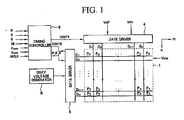
- the LCD includes a TFT display panel 1, a gate driver 4 connected to the TFT display panel 1, a data driver 5, a gray voltage generator 8 connected to the data driver 5, and a timing controller 6 for controlling the drivers.
- the TFT display panel 1 includes a plurality of display signal lines G 1 , G 2 , ... G n-1, G n , D 1, D 2, .. D m-1, D m and a plurality of pixels P x connected thereto and substantially in a matrix.
- Gate lines G 1 , G 2 , ... Gn-1, Gn transmit gate signals while data lines D 1, D 2, D m-1 , D m transmit data signals.
- the gate lines G 1 , G 2 , ... Gn-1, Gn extend in a column direction and are substantially parallel to each other, while the data lines D 1, D 2, ... D m-1, D m extend in a row direction and are substantially parallel to each other.
- the TFT panel 1 of the LCD according to embodiments of the present invention will be described below in more detail.
- the gray voltage generator 8 generates two sets of a plurality of gray voltages related to the transmittance of the pixels P x .
- the gray voltages in one set have a positive polarity with respect to a common voltage V COM , while those in the other set have a negative polarity with respect to the common voltage V COM .
- the gate driver 4 is connected to the gate lines G 1 , G 2 , ... Gn-1, Gn of the TFT panel 1 and synthesizes the gate-on voltage Von and the gate off voltage Voff from an external device to generate gate signals for application to the gate lines G 1 , G 2 , ... Gn-1, Gn.
- the data driver 5 is connected to the data lines D 1, D 2, ... D m-1, D m of the TFT panel 1 and applies data voltages, selected from the gray voltages supplied from the gray voltage generator 8, to the data lines D 1, D 2 , ... D m-1, D m .
- the data driver 5 may include a plurality of ICs.
- the timing controller 6 generates control signals for controlling the operations of the gate driver 4 and the data driver 5 and supplies the gate driver 4 and the data driver 5 with the corresponding control signals.
- the timing controller 6 is supplied with red, green and blue image signals R, G, B and input control signals controlling the display thereof such as a vertical synchronization signal V sync , a horizontal synchronization signal H sync , a main clock MCLK, and a data enable signal DE, from an external graphics controller (not shown).
- the timing controller 6 After generating gate control signals CONT1 and data control signals CONT2 and processing and modifying the three color input image signals R, G, B into four color image signals R', G', B' suitable for the operation of the TFT panel 1 on the basis of the input control signals and the image signals R, G, B, the timing controller 6 provides the gate control signals CONT1 for the gate driver 4, and the processed and modified image signals R', G', B' and the data control signals CONT2 for the data driver 5.
- the gate control signals CONT1 include a scanning start signal STV for instructing to start scanning, at least a clock signal for controlling the output of the gate-on voltage Von, a gate clock signal CPV for controlling the output timing of the gate-on voltage Von, and an output enable signal OE for defining a pulse width of the gate-on voltage Von.
- the data control signals CONT2 include a horizontal synchronization start signal STH for informing of start of a horizontal period, a load signal LOAD for instructing to apply the data voltages to the data lines D 1, D 2, ... D m-1, D m , an inversion control signal RVS for reversing the polarity of the data voltages (with respect to the common voltage V COM ), and a data clock signal HCLK.
- the data driver 5 receives a packet of the image data R', G', B' for a row of pixels P x from the timing controller 6 and converts the image data R', G', B' into analog data voltages selected from the gray voltages supplied from the gray voltage generator 8 in response to the data control signals CONT2 from the timing controller 6.
- the gate driver 4 Responsive to the vertical synchronization start signal STV and the gate clock signal CPV supplied from the timing controller 6, the gate driver 4 applies the gate-on voltage Von having a period of 1/2 H to the gate lines G 1 , G 2 , ... Gn-1, Gn to turn on the switching elements Q 1 , Q 2 (see FIG. 2 ) connected to the gate lines G 1 , G 2 , ... Gn-1, Gn.
- the gate-on voltage Von may be sequentially applied to the gate lines G 1 , G 2 , ... Gn-1, Gn in a row direction.
- the data driver 5 applies the data voltages to the data lines D 1, D 2, ... D m-1, D m .
- the data voltages applied to the data lines D 1, D 2, ... D m-1, D m are applied to the corresponding pixels P x through the turned-on switching elements Q 1 , Q 2 .
- the gate-on voltage Von is sequentially applied to all the gate lines G 1 , G 2 , ... Gn-1, Gn to apply data voltages to all the pixels.
- the inversion control signal RVS applied to the data driver 5 is controlled such that the polarity of the data voltages is reversed (which is called “frame inversion”).
- the inversion control signal RVS may be also controlled such that the polarity of the data voltages flowing in a data line in one frame are reversed (which is called “line inversion”), or the polarity of the data voltages in one pixel row are reversed (which is called “dot inversion").
- the gate driver 4 may be formed of IC chips at one side or upper and lower sides of the TFT display panel 1, thereby preventing the TFT display panel 1 from becoming bulky.
- FIG. 2 is an equivalent circuit diagram of a TFT display panel 1 of an LCD
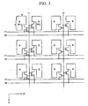
- FIG. 3 illustrates a pixel array of the LCD shown in FIG. 2 .
- the LCD will now be described with reference to FIGs. 1 through 3 .
- a pixel array having a plurality of pixels in a matrix is formed on a substrate.
- first and second pixels P 1 , P 2 of FIG. 3 which are adjacent to each other in a first direction m, include first and second switching elements Q 1 , Q 2 of FIG. 2 , respectively.
- a liquid crystal capacitor C 1c and a storage capacitor C st are connected to each of the switching elements Q 1 , Q 2 . If unnecessary, the storage capacitor C st may be omitted.
- the switching elements Q 1 , Q 2 have three terminals.
- a gate terminal is connected to a first common gate line 11.
- a source terminal is connected to first or second data lines 21, 22.
- a drain terminal is connected to the liquid crystal capacitor C 1c and the storage capacitor C st .
- the first and second data lines 21, 22 extend in the first direction m.
- the switching elements Q 1 , Q 2 are commonly connected to the first common gate line 11 extending in a second direction n that is different from the first direction m.
- the switching elements Q 1 , Q 2 are connected to the gate lines 11, 12 and the data lines 21, 22 as follows.
- the switching elements Q 1 , Q 2 are positioned at left and right sides of the first common gate line 11 in the first direction m.
- the switching element Q 1 positioned at the left side of the first common gate line 11 has its source electrode connected to the first data line 21, and the switching element Q 2 positioned at the right side of the first common gate line 11 has its source electrode connected to the second data line 22, forming a row of pixels.
- the connection relationship of the switching elements Q 1 , Q 2 with respect to the gate lines 11, 12 and the data lines 21, 22 may be reversed.
- the switching element Q 1 positioned at the left side of the first common gate line 11 may have its source electrode connected to the second data line 22, and the switching element Q 2 positioned at the right side of the first common gate line 11 may have its source electrode connected to the first data line 21, forming a row of pixels.
- the first and second data lines 21, 22 may be a pair on each row of the pixel array.
- Each of the pixels sharing common gate line 11 includes one of the switching elements Q 31 , Q 32 , Q 33 , Q 34 , Q 35 , Q 36 .
- the switching elements Q 31 , Q 33 , Q 35 or the switching elements Q 32 , Q 34 , Q 36 of a column of pixels in the pixel array may be alternately connected to the first data line 21 and the second data line 22 for each row of the pixel array.
- the switching element Q 31 of the first row is connected to the first data line 21.
- the switching element Q 33 of the second row is connected to the second data line 22.
- the switching element Q 35 of the third row is connected to the first data line 21.
- the switching element Q 32 of the first row is connected to the second data line 22.
- the switching element Q 34 of the second row is connected to the first data line 21.
- the switching element Q 36 of the third row is connected to the second data line 22.
- the connection relationship of the switching elements in the pixel array may be reversed.
- the liquid crystal capacitor C 1c includes a pixel electrode provided on the TFT display panel 1 and a common electrode provided on a color filter display panel as two terminals. A liquid crystal layer between the two electrodes functions as a dielectric of the liquid crystal capacitor C 1c .
- the pixel electrode is connected to the switching elements Q 1 , Q 2 , and the common electrode is formed on the entire surface of the TFT display panel 1 and receives the common voltage V COM .
- the storage capacitor C st includes the pixel electrode and a separate signal line (not shown), which is provided on the TFT display panel 1, overlaps the pixel electrode via an insulator, and is supplied with a predetermined voltage such as the common voltage V COM .
- the storage capacitor C st includes the pixel electrode and an adjacent gate line called a previous gate line, which overlaps the pixel electrode via an insulator.
- the substrate for the TFT display panel I of FIG. 1 having the pixel array may have long sides and short sides. As seen in FIG. 1 , the long sides are substantially parallel to the first direction m, and the short sides are substantially parallel to the second direction n. Accordingly, the data driver 5 may be at the short sides of the substrate.
- a length a of each of the first and second pixels P 1 , P 2 in the second direction n is greater than a length b thereof in the first direction m.
- the pixel array may alternately represent colors of red (R), green (G) and blue (B) in the first direction m (i.e., in a row direction) and represent the same color in the second direction n (i.e., in a column direction).
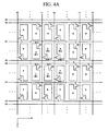
- FIG. 4A illustrates a pixel array of an LCD according to an exemplary first embodiment of the present invention.
- FIG. 4B illustrates that signals applied to data lines of the pixel array shown in FIG. 4A are subjected to 2 ⁇ 1 inversion.
- FIG. 4C illustrates that signals applied to data lines of the pixel array shown in FIG. 4A are subjected to column inversion.
- the LCD according to the exemplary embodiment of the present invention will now be described with reference to FIGs. 4A through 4C .
- first and second pixels P 1 , P 2 adjacent to each other along a first direction m, include first and second switching elements Q 41 , Q 42 , respectively.
- the first common gate line 11 extends in a second direction n different from the first direction m, and is commonly connected to the first and second switching elements Q 41 , Q 42 .
- the first and second data lines 21, 22 extend in the first direction m, and are connected to the first and second switching elements Q 41 , Q 42 , respectively.
- the LCD according to the exemplary embodiment of the present invention further includes a third data line 23 on the substrate.
- the first through third data lines 21, 22, 23 are on the substrate at repeated intervals.
- the first to third data lines 21, 22, 23 are such that six pixels included in the pixel array are in a 2x3 matrix portion A in FIG. 4A . That is to say, the first and second data lines 21, 22 are such that the first pixel row is between the first data line 21 and the second data line 22, and the second and third data lines 22, 23 are opposed to and substantially parallel to each other.
- the third and first data lines 23, 21 are such that the second pixel row is between the third data line 23 and the first data line 21.
- pixels P 1 , P 2 , P 3 belong to the first pixel row and pixels P 4 , P 5 , P 6 belong to the second pixel row.
- the LCD according to the exemplary embodiment of the present invention further includes a second common gate line 12.
- the first and second common gate lines 11, 12 are on the substrate at repeated intervals.
- the second common gate line 12 is adjacent to and substantially parallel to the first common gate line 11, and the second pixel P 2 is positioned between the first and second common gate lines 11, 12.
- first through third data lines 21, 22, 23 and the first and second common gate lines 11, 12 six pixels P 1 , P 2, P 3, P 4, P 5, P 6 in the portion A in FIG. 4A are in a 2x3 matrix.
- the connection relationships among the first through third data lines 21, 22, 23, the first and second common gate lines 11, 12, and the switching elements Q 41, Q 42, Q 43, Q 44, Q 45, Q 46 respectively included in the six pixels P 1 , P 2, P 3, P 4, P 5, P 6 is described below in more detail.
- the first and second pixels P 1 , P 2 , and the third pixel P 3 which includes the third switching element Q 43 are along the first direction m.
- the fourth to sixth pixels P 4 , P s, P 6, respectively including the fourth to sixth switching elements Q 44 , Q 45, Q 46, are along the first direction m.
- the third switching element Q 43 is connected to the second common gate line 12 and the second data line 22.
- the fourth switching element Q 44 is connected to the first common gate line 11 and the third data line 23.
- the fifth switching element Q 45 is connected to the second common gate line 12 and the third data line 23.
- the sixth switching element Q 46 is connected to the second common gate line 12 and the first data line 21.
- the pixel array of the LCD according to the exemplary embodiment of the present invention has an overall 2 ⁇ 3 matrix occurring at repeated intervals.
- a first signal is consecutively applied twice to the first through third data lines 21, 22, 23, respectively, and then a second signal is consecutively applied twice thereto.
- the first and second signals are inversion control signals RVS that inverse the polarity of a data voltage. That is to say, the first signal may be a positive (+) data voltage, and the second signal may be a negative (-) data voltage, or vice versa.
- the first signal is a negative (-) data voltage
- the second signal is a positive (+) data voltage
- the first signal i.e., a negative (-) data voltage
- the second signal i.e., a positive (+) data voltage
- the twice applied first signal i.e., the negative (-) data voltage
- the pixels having the two switching elements Q 47 , Q 48 have negative (-) polarities.
- the twice applied second signal i.e., the positive (+) data voltage is applied to the two switching elements Q 49 , Q 50 which are also connected to the third data line 23. Accordingly, pixels including the two switching elements Q 49 , Q 50 have positive (+) polarities.
- a first signal and a second signal having opposite polarities of those applied to the third data line 23 are applied to the first data line 21 adjacent to the upper third data line 23. That is to say, the first signal, i.e., the positive (+) data voltage, is consecutively applied to the first data line 21 twice. Next, the second signal, i.e., the negative (-) data voltage, is consecutively applied to the first data line 21 twice.
- first signal and the second signal having opposite polarities of those applied to the first data line 21 are applied to the second data line 22 adjacent to the first data line 21.
- Polar staining which may appear on a particular pixel array can be prevented by performing 2 ⁇ 1 inversion on the data signals and the pixel array having the 2 ⁇ 3 matrix occurring at repeated intervals.
- one single data line i.e., the first data line 21, and a pair of data lines, i.e., the second and third data lines 22, 23, are alternately in a row, thereby preventing horizontal stripes from being visible on the LCD.
- the first and second signals are alternately applied to the respective first through third data lines 21, 22, 23. That is to say, when the first signal is applied to the first data line 21, the second signal is applied to the second data line 22 and the first signal is again applied to the data line 23. Accordingly, the signals applied to the respective first through third data lines 21, 22, 23 are subjected to column inversion.
- the first signal and the second signal are substantially the same as described above.
- the first signal i.e., a positive (+) data voltage
- the second signal i.e., a negative (-) data voltage
- the first signal i.e., the positive (+) data voltage
- the second signal is again applied to the second data line 22 adjacent to the first data line 21, and vice versa.
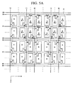
- FIG. 5A illustrates a pixel array of an LCD according to an exemplary second embodiment of the present invention
- FIG. 5B illustrates that signals applied to data lines of the pixel array shown in FIG. 5A are subjected to column inversion.
- first and second pixels P 1 , P 2 adjacent to each other along a first direction m, include first and second switching elements Q 501 , Q 502 , respectively.
- the first common gate line 11 extends in a second direction n different from the first direction m, and is commonly connected to the first and second switching elements Q 501 , Q 502 .
- the first and second data lines 21, 22 extend in the first direction m, and are connected to the first and second switching elements Q 501 , Q 502 , respectively.
- the LCD according to the exemplary embodiment of the present invention further includes a third data line 23 on the substrate.
- the first through third data lines 21, 22, 23 are on the substrate at repeated intervals.
- the first through third data lines 21, 22, 23 are such that 12 pixels in a portion B in FIG. 5B belonging to the pixel array are in a 2 ⁇ 6 matrix at repeated intervals.
- the second data line and the first data line 22, 21 are in the first pixel row positioned between the second data line 22 and the first data line 21.
- the first data line 21 and the third data line 23 are in the second pixel row positioned between the first data line 21 and the third data line 23.
- the third data line 23 and the second data line 22 are opposed to each other.
- pixels P 1 , P 2, P 3, P 4, P 5, P 6 belong to the first pixel row of the portion B in FIG. 5A .
- Pixels P 7 , P 8, P 9, P 10, P 11, P 12 belong to the second pixel row of the portion B.
- the LCD according to the exemplary embodiment of the present invention further includes a second common gate line 12.
- the first and second common gate lines 11, 12 are substantially the same as those according to the exemplary embodiment of FIG. 4A , and a repeated explanation thereof will not be given.
- first through third data lines 21, 22, 23 and the first and second common gate lines 11, 12, 12 pixels P 1 , P 2, P 3, P 4, P 5, P 6, P 7 , P 8, P 9, P 10, P 11 , P 12 in the portion B in FIG. 5A are in a 2 ⁇ 6 matrix.
- the connection relationships among the first through third data lines 21, 22, 23, the first and second common gate lines 11, 12, and the switching elements Q 501 , Q 502, Q 503, Q 504, Q 505, Q 506, Q 507, Q 508, Q 509, Q 510, Q 511, Q 512 respectively included in the 12 pixels P 1 , P 2, P 3, P 4, P 5, P 6, P 7, P 8, P 9, P 10, P 11, P 12, is described below in more detail.
- first and second pixels P 1 , P 2 and third to sixth pixels P 3 , P 4 , P 5, P 6 , respectively including third to sixth switching elements Q 503, Q 504, Q 505, Q 506, are along the first direction m.
- seventh to twelfth pixels P 7, P 8, P 9, P 10, P 11, P 12 respectively including seventh to twelfth elements Q 507 , Q 508, Q 509, Q 510, Q 511, Q 512, are along the first direction m.
- the third switching element Q 503 is connected to the second common gate line 12 and the second data line 22.
- the fourth switching element Q 504 is connected to the first common gate line 11 and the second data line 22.
- the fifth switching element Q 505 is connected to the second common gate line 12 and the second data line 22.
- the sixth switching element Q 506 is connected to the second common gate line 12 and the first data line 21.
- the seventh switching element Q 507 is connected to the first common gate line 11 and the third data line 23.
- the eighth switching element Q 508 is connected to the second common gate line 12 and the third data line 23.
- the ninth switching element Q 509 is connected to the second common gate line 12 and the first data line 21.
- the tenth switching element Q 510 is connected to the first common gate line 11 and the first data line 21.
- the eleventh switching element Q 511 is connected to the first common gate line 11 and the third data line 23.
- the twelfth switching element Q 512 is connected to the second common gate line 12 and the third data line 23
- the pixel array of the LCD according to the exemplary embodiment of the present invention has the overall 2 ⁇ 6 matrix occurring at repeated intervals.
- a first signal and a second signal are alternately applied to the first to third data lines 21, 22, 23, respectively, which is substantially the same as described for the exemplary embodiment of FIG. 4A and a repeated explanation thereof will not be given.
- FIG. 6A illustrates a pixel array of an LCD according to an exemplary third embodiment of the present invention
- FIG. 6B illustrates that signals applied to data lines of the pixel array shown in FIG. 6A are subjected to column inversion.
- the first to third data lines 21, 22, 23 are such that 12 pixels included in the pixel array are in a 2 ⁇ 6 matrix C in FIG. 6A and the first and second data lines 21, 22 are such that the first pixel row is between the first data line 21 and the second data line 22.
- the second and third data lines 22, 23 are such that the second pixel row is between the second data line 22 and the third data line 23.
- the third and first data lines 23, 21 are opposed to and substantially parallel to each other.
- the LCD according to the exemplary embodiment of FIG. 6A further includes a second common gate line 12, which is substantially the same as described for the exemplary embodiment of FIG. 4A and a repeated explanation thereof will not be given.
- first through third data lines 21, 22, 23 and the first and second common gate lines 11, 12, 12 pixels P 1 , P 2, P 3, P 4, P 5, P 6, P 7, P 8, P 9, P 10, P 11 , P 12 in the portion C in FIG. 6A are in a 2 ⁇ 6 matrix.
- the connection relationships among the first through third data lines 21, 22, 23, the first and second common gate lines 11, 12, and switching elements Q 601 , Q 602, Q 603, Q 604, Q 605, Q 606, Q 607, Q 608, Q 609, Q 610, Q 611, Q 612, respectively included in the 12 pixels P 1 , P 2, P 3, P 4, P 5, P 6, P 7, P 8, P 9, P 10, P 11 P 12 , is described below in more detail.
- first and second pixels P 1 , P 2 and third to sixth pixels P 3 , P 4 P 5, P 6 , respectively including third to sixth switching elements Q 603 , Q 604, Q 605, Q 606, are along the first direction m.
- seventh to twelfth pixels P 7 , P 8, P 9, P 10, P 11, P 12, respectively including seventh to twelfth elements Q 607 , Q 608, Q 609, Q 610, Q 611, Q 612, are along the first direction m.
- the third switching element Q 603 is connected to the second common gate line 12 and the first data line 21.
- the fourth switching element Q 604 is connected to the first common gate line 11 and the first data line 21.
- the fifth switching element Q 605 is connected to the second common gate line 12 and the first data line 21.
- the sixth switching element Q 606 is connected to the second common gate line 12 and the second data line 22.
- the seventh switching element Q 607 is connected to the first common gate line 11 and the third data line 23.
- the eighth switching element Q 608 is connected to the second common gate line 12 and the second data line 22.
- the ninth switching element Q 609 is connected to the second common gate line 12 and the third data line 23.
- the tenth switching element Q 610 is connected to the first common gate line 11 and the second data line 22.
- the eleventh switching element Q 611 is connected to the first common gate line 11 and the third data line 23.
- the twelfth switching element Q 612 is connected to the second common gate line 12 and the third data line 23
- the pixel array of the LCD according to the exemplary embodiment of FIG. 6A has an overall 2 ⁇ 6 matrix occurring at repeated intervals.
- a first signal and a second signal are alternately applied to the first to third data lines 21, 22, 23, respectively, which is substantially the same as described for the exemplary embodiment of FIG. 4A and a repeated explanation thereof will not be given.
Landscapes
- Physics & Mathematics (AREA)
- Engineering & Computer Science (AREA)
- General Physics & Mathematics (AREA)
- Nonlinear Science (AREA)
- Crystallography & Structural Chemistry (AREA)
- Chemical & Material Sciences (AREA)
- Computer Hardware Design (AREA)
- Theoretical Computer Science (AREA)
- Mathematical Physics (AREA)
- Optics & Photonics (AREA)
- Microelectronics & Electronic Packaging (AREA)
- Liquid Crystal (AREA)
- Liquid Crystal Display Device Control (AREA)
- Control Of Indicators Other Than Cathode Ray Tubes (AREA)
Description
- The present disclosure relates to a liquid crystal display, and more particularly, to liquid crystal display pixel arrays.
- A liquid crystal display (LCD) is a widely used flat panel display (FPD). It is composed of two display panels on which are formed field generating electrodes, such as pixel electrodes and a common electrode. A liquid crystal layer is interposed between the two display panels. A voltage is applied to the field generating electrodes to generate an electric field in the liquid crystal layer. The orientation of liquid crystal molecules of the liquid crystal layer is determined and the polarization of incident light is controlled through the generated electric field to display an image.
- In the LCD, a thin film transistor (TFT) array includes gate lines for transmitting scanning signals and data lines for transmitting data lines crossing each other to define pixels. Each pixel of the array includes a TFT connected to a gate line and a data line, and a pixel electrode connected to the TFT. A pixel array is formed on the TFT array using a plurality of pixels, each including the TFT.
- Since a data driver of an LCD is typically a high-priced, highly functional device as compared to a gate driver, it becomes difficult to mount the data driver directly on a glass substrate using amorphous silicon TFTs. In addition, as the number of channels used increases, the manufacturing cost sharply increases. Therefore, in order to reduce the manufacturing cost, it becomes helpful to reduce the number of channels. It also becomes helpful for the LCDs to have pixel arrays which provide sufficient charging time for the gate driver circuits.
- Document
US 2007/0008263 A1 is directed to a liquid crystal display including a plurality of pixels arranged in the form of a matrix and having first and second sub-pixels. A plurality of gate lines are connected to the first and second sub-pixels to transmit gate signals thereto. A plurality of first and second data lines cross the gate lines, and are connected to the first and second sub-pixels to transmit first and second data voltages thereto, respectively. A data driver outputs the first and second data voltages to the first and second data lines, respectively. The first and second data voltages have the same polarity. A pixel is divided into two sub-pixels, and different data voltages are separately applied to the two sub-pixels, thereby enhancing visibility. - Document
JP 2006 195436 A - An exemplary embodiment of the present invention according to the claims provides an LCD which reduces the number of channels and provides appropriate charging time for gate driver circuits.
- An exemplary embodiment of an LCD according to the claims includes a pixel array having a plurality of pixels in a matrix on a substrate. The matrix has at least a first pixel row and a second pixel row adjacent the first pixel row. Both the first pixel row and the second pixel row extend in a first direction. A first pixel and a second pixel of the first pixel row are adjacent to each other along the first direction. The first pixel and the second pixel respectively include a first switching element and a second switching element. A first common gate line extends in a second direction different from the first direction and is commonly connected to the first switching element and to the second switching element. A first data line and a second data line extend in the first direction and are connected to the first switching element and to the second switching element, respectively.
- The substrate may have a long side and a short side, the long side being substantially parallel to the first direction, and the short side being substantially parallel to the second direction.
- A length of the first pixel in the second direction may be greater than a length of the first pixel in the first direction.
- The pixel array may alternately display colors of red, green and blue in the first direction and display the same color in the second direction.
- A pair of a first data line and a second data line are in each row of the pixel array.
- Each of the pixels includes a switching element, respectively, and switching elements of a column of pixels in the pixel array may be alternately connected to a first data line of a row and to a second data line in an adjacent row.
- A third data line is further provided on the substrate. The first data line, the second data line and the third data line is on the substrate at repeated intervals. The second data line and the third data line may be opposed to and substantially parallel to each other. The first pixel row may be between the first data line and the second data line. The second pixel row may be between the third data line and the first data line.
- A second common gate line is further provided on the substrate. The first common gate line and second common gate line is on the substrate at repeated intervals. The second common gate line is adjacent to and substantially parallel to the first common gate line. The second pixel is between the first common gate line and the second common gate line.
- In a first embodiment the pixel array includes six pixels in a 2×3 matrix, the six pixels including the first pixel, the second pixel, a third pixel, a fourth pixel, a fifth pixel and a sixth pixel. The first pixel, the second pixel, and the third pixel having a third switching element, are in the first pixel row, The fourth pixel, the fifth pixel and the sixth pixel, respectively including a fourth switching element, a fifth switching element and a sixth switching element, are in the second pixel row. The third switching element is connected to the second common gate line and to the second data line. The fourth switching element is connected to the first common gate line and to the third data line. The fifth switching element is connected to the second common gate line and to the third data line. The sixth switching element is connected to the second common gate line and to the first data line.
- To the first data line, a first signal is consecutively applied twice followed by a second signal consecutively applied twice, at repeated intervals. To the second data line, the second signal is consecutively applied twice followed by the first signal consecutively applied twice, at repeated intervals. To the third data line, the first signal is consecutively applied twice followed by the second signal consecutively applied twice, at repeated intervals.
- The first signal and the second signal are alternately applied to adjacent data lines.
- A third data line is further provided on the substrate. The first data line, the second data line and the third data line are on the substrate at repeated intervals. The third data line and the second data line are opposed to and substantially parallel to each other. The first pixel row is between the second data line and the first data line. The second pixel row is between the first data line and the third data line.
- A second common gate line is further provided on the substrate. The first common gate line and the second common gate line are on the substrate at repeated intervals. The second common gate line is adjacent to and substantially parallel to the first common gate line. The second pixel is between the first common gate line and the second common gate lines.
- In a second embodiment the pixel array includes 12 pixels in a 2×6 matrix. The first pixel row includes the first pixel, the second pixel, a third pixel, a fourth pixel, a fifth pixel and a sixth pixel, respectively including the first switching element, the second switching element, a third switching element, a fourth switching element, and a sixth switching element, along the first direction. The second pixel row includes a seventh pixel, an eighth pixel, a ninth pixel, a tenth pixel, an eleventh pixel and a twelfth pixel, respectively including a seventh switching element, an eighth switching element, a ninth switching element, a tenth switching element an eleventh switching element and a twelfth switching element, along the first direction, The third switching element is connected to the second common gate line and to the second data line. The fourth switching element is connected to a second first common gate line and to the second data line. The fifth switching element is connected to a second second common gate line and to the second data line. The sixth switching element is connected to the second second common gate line and to the first data line. The seventh switching element is connected to the first common gate line and to the third data line. The eighth switching element is connected to the second common gate line and to the third data line. The ninth switching element is connected to the second common gate line and to the first data line. The tenth switching element is connected to a second first common gate line and to the first data line. The eleventh switching element is connected to the second first common gate line and to the third data line. The twelfth switching element is connected to the second second common gate line and to the third data line.
- The first signal and the second signal are alternately applied to adjacent data lines.
- A third data line is further provided on the substrate. The first data line, the second data line and the third data line are on the substrate at repeated intervals. The third data line and the first data line are opposed to and substantially parallel to each other. The first pixel row is between the first data line and the second data line. The second pixel row is between the second data line and the third data line.
- A second common gate line is further provided on the substrate. The first common gate line and the second common gate line are on the substrate at repeated intervals. The second common gate line is adjacent to and substantially parallel to the first common gate line. The second pixel is between the first common gate line and the second common gate line.
- In a third embodiment the pixel array includes 12 pixels in a 2×6 matrix. The first pixel row includes the first pixel, the second pixel, a third pixel, a fourth pixel, a fifth pixel and a sixth pixel, respectively including the first switching element, the second switching element, a third switching element, a fourth switching element, a fifth switching element and a sixth switching element, along the first direction. The second pixel row includes a seventh pixel, an eighth pixel, a ninth pixel, a tenth pixel, an eleventh pixel and a twelfth pixel, respectively including a seventh switching element, an eighth switching element, a ninth switching element, a tenth switching element, an eleventh switching element and a twelfth switching element, along the first direction. The third switching element is connected to the second common gate line and to the first data line. The fourth switching element is connected to a second first common gate line and to the first data line. The fifth switching element is connected to a second second common gate line and to the first data line. The sixth switching element is connected to the second second common gate line and to the second data line. The seventh switching element is connected to the first common gate line and to the third data line. The eighth switching element is connected to the second common gate line and to the second data line. The ninth switching element is connected to the second common gate line and to the third data line. The tenth switching element is connected to the second first common gate line and to the second data line. The eleventh switching element is connected to the second first common gate line and to the third data line. The twelfth switching element is connected to the second second common gate line and to the third data line.
- The first signal and the second signal are alternately applied to adjacent data lines.
- The above and other features of the present invention will become more apparent by describing in detail exemplary embodiments thereof with reference to the attached drawings in which:
-
FIG. 1 is an exemplary block diagram of an LCD; -
FIG. 2 is an equivalent circuit diagram of a TFT display panel of the LCD shown inFIG. 1 ; -
FIG. 3 illustrates a pixel array of the LCD shown inFIG. 2 ; -
FIG. 4A illustrates a pixel array of the LCD according to an exemplary embodiment of the present invention; -
FIG. 4B illustrates signals applied to data lines of the pixel array shown inFIG. 4A being subjected to 2×1 inversion; -
FIG. 4C illustrates signals applied to data lines of the pixel array shown inFIG. 4A being subjected to column inversion; -
FIG. 5A illustrates a pixel array of an LCD according to an exemplary embodiment of the present invention; -
FIG. 5B illustrates signals applied to data lines of the pixel array shown inFIG. 5A being subjected to column inversion; -
FIG. 6A illustrates a pixel array of an LCD according to an exemplary embodiment of the present invention; and -
FIG. 6B illustrates signals applied to data lines of the pixel array shown inFIG. 6A being subjected to column inversion. - It will be understood that when an element or layer is referred to as being "on" another element or layer, it can be directly on to the other element or layer or intervening elements or layers may be present. Like reference numerals refer to like elements throughout the specification.
- Hereinafter, LCDs according to exemplary embodiments of the present invention will be described with reference to the accompanying drawings.
- Referring now to
FIG. 1 , the LCD includes aTFT display panel 1, agate driver 4 connected to theTFT display panel 1, a data driver 5, agray voltage generator 8 connected to the data driver 5, and a timing controller 6 for controlling the drivers. - The
TFT display panel 1 includes a plurality of display signal lines G1, G2, ... Gn-1, Gn, D1,D2,.. Dm-1, Dm and a plurality of pixels Px connected thereto and substantially in a matrix. Gate lines G1, G2, ... Gn-1, Gn transmit gate signals while data lines D1, D2, Dm-1, Dm transmit data signals. - The gate lines G1, G2, ... Gn-1, Gn extend in a column direction and are substantially parallel to each other, while the data lines D1, D2, ... Dm-1, Dm extend in a row direction and are substantially parallel to each other. The
TFT panel 1 of the LCD according to embodiments of the present invention will be described below in more detail. - The
gray voltage generator 8 generates two sets of a plurality of gray voltages related to the transmittance of the pixels Px. The gray voltages in one set have a positive polarity with respect to a common voltage VCOM, while those in the other set have a negative polarity with respect to the common voltage VCOM. - The
gate driver 4 is connected to the gate lines G1, G2, ... Gn-1, Gn of theTFT panel 1 and synthesizes the gate-on voltage Von and the gate off voltage Voff from an external device to generate gate signals for application to the gate lines G1, G2, ... Gn-1, Gn. - The data driver 5 is connected to the data lines D1, D2, ... Dm-1, Dm of the
TFT panel 1 and applies data voltages, selected from the gray voltages supplied from thegray voltage generator 8, to the data lines D1, D2, ... Dm-1, Dm. The data driver 5 may include a plurality of ICs. - The timing controller 6 generates control signals for controlling the operations of the
gate driver 4 and the data driver 5 and supplies thegate driver 4 and the data driver 5 with the corresponding control signals. - Now, the operation of the LCD will be described in more detail.
- The timing controller 6 is supplied with red, green and blue image signals R, G, B and input control signals controlling the display thereof such as a vertical synchronization signal Vsync, a horizontal synchronization signal Hsync, a main clock MCLK, and a data enable signal DE, from an external graphics controller (not shown). After generating gate control signals CONT1 and data control signals CONT2 and processing and modifying the three color input image signals R, G, B into four color image signals R', G', B' suitable for the operation of the
TFT panel 1 on the basis of the input control signals and the image signals R, G, B, the timing controller 6 provides the gate control signals CONT1 for thegate driver 4, and the processed and modified image signals R', G', B' and the data control signals CONT2 for the data driver 5. - The gate control signals CONT1 include a scanning start signal STV for instructing to start scanning, at least a clock signal for controlling the output of the gate-on voltage Von, a gate clock signal CPV for controlling the output timing of the gate-on voltage Von, and an output enable signal OE for defining a pulse width of the gate-on voltage Von.
- The data control signals CONT2 include a horizontal synchronization start signal STH for informing of start of a horizontal period, a load signal LOAD for instructing to apply the data voltages to the data lines D1, D2, ... Dm-1, Dm, an inversion control signal RVS for reversing the polarity of the data voltages (with respect to the common voltage VCOM), and a data clock signal HCLK.
- The data driver 5 receives a packet of the image data R', G', B' for a row of pixels Px from the timing controller 6 and converts the image data R', G', B' into analog data voltages selected from the gray voltages supplied from the
gray voltage generator 8 in response to the data control signals CONT2 from the timing controller 6. - Responsive to the vertical synchronization start signal STV and the gate clock signal CPV supplied from the timing controller 6, the
gate driver 4 applies the gate-on voltage Von having a period of 1/2 H to the gate lines G1, G2, ... Gn-1, Gn to turn on the switching elements Q1, Q2 (seeFIG. 2 ) connected to the gate lines G1, G2, ... Gn-1, Gn. Here, the gate-on voltage Von may be sequentially applied to the gate lines G1, G2, ... Gn-1, Gn in a row direction. - While the gate-on voltage Von is applied to the gate lines G1, G2, ... Gn-1, Gn and the switching elements Q1, Q2 connected to the gate lines G1, G2, ... Gn-1, Gn are turned on, the data driver 5 applies the data voltages to the data lines D1, D2,... Dm-1, Dm.
- The data voltages applied to the data lines D1, D2, ... Dm-1, Dm are applied to the corresponding pixels Px through the turned-on switching elements Q1, Q2.
- A variation in electric fields generated by pixel electrodes (not shown) in cooperation with a common electrode (not shown) reorients liquid crystal molecules, and the variation in the polarized light causes a change in the transmittance of light by a polarizer (not shown) attached to a display panel (not shown).
- In this manner, during a period of one frame, the gate-on voltage Von is sequentially applied to all the gate lines G1, G2, ... Gn-1, Gn to apply data voltages to all the pixels. When the next frame starts after finishing one frame, the inversion control signal RVS applied to the data driver 5 is controlled such that the polarity of the data voltages is reversed (which is called "frame inversion"). The inversion control signal RVS may be also controlled such that the polarity of the data voltages flowing in a data line in one frame are reversed (which is called "line inversion"), or the polarity of the data voltages in one pixel row are reversed (which is called "dot inversion").
- The
gate driver 4 may be formed of IC chips at one side or upper and lower sides of theTFT display panel 1, thereby preventing theTFT display panel 1 from becoming bulky. -
FIG. 2 is an equivalent circuit diagram of aTFT display panel 1 of an LCD , andFIG. 3 illustrates a pixel array of the LCD shown inFIG. 2 . The LCD will now be described with reference toFIGs. 1 through 3 . - A pixel array having a plurality of pixels in a matrix is formed on a substrate.
- In the pixel array, first and second pixels P1, P2 of
FIG. 3 , which are adjacent to each other in a first direction m, include first and second switching elements Q1, Q2 ofFIG. 2 , respectively. A liquid crystal capacitor C1c and a storage capacitor Cst are connected to each of the switching elements Q1, Q2. If unnecessary, the storage capacitor Cst may be omitted. - The switching elements Q1, Q2 have three terminals. A gate terminal is connected to a first
common gate line 11. A source terminal is connected to first or second data lines 21, 22. A drain terminal is connected to the liquid crystal capacitor C1c and the storage capacitor Cst. Here, the first and second data lines 21, 22 extend in the first direction m. - The switching elements Q1, Q2 are commonly connected to the first
common gate line 11 extending in a second direction n that is different from the first direction m. - In more detail, the switching elements Q1, Q2 are connected to the gate lines 11, 12 and the data lines 21, 22 as follows.
- The switching elements Q1, Q2 are positioned at left and right sides of the first
common gate line 11 in the first direction m. The switching element Q1 positioned at the left side of the firstcommon gate line 11 has its source electrode connected to thefirst data line 21, and the switching element Q2 positioned at the right side of the firstcommon gate line 11 has its source electrode connected to thesecond data line 22, forming a row of pixels. Alternatively, the connection relationship of the switching elements Q1, Q2 with respect to the gate lines 11, 12 and the data lines 21, 22 may be reversed. That is to say, the switching element Q1 positioned at the left side of the firstcommon gate line 11 may have its source electrode connected to thesecond data line 22, and the switching element Q2 positioned at the right side of the firstcommon gate line 11 may have its source electrode connected to thefirst data line 21, forming a row of pixels. - Referring to
FIG. 3 , the first and second data lines 21, 22 may be a pair on each row of the pixel array. Each of the pixels sharingcommon gate line 11 includes one of the switching elements Q31, Q32, Q33, Q34, Q35, Q36. Here, the switching elements Q31, Q33, Q35 or the switching elements Q32, Q34, Q36 of a column of pixels in the pixel array may be alternately connected to thefirst data line 21 and thesecond data line 22 for each row of the pixel array. In the left pixel column as viewed relative to the firstcommon gate line 11, the switching element Q31 of the first row is connected to thefirst data line 21. The switching element Q33 of the second row is connected to thesecond data line 22. The switching element Q35 of the third row is connected to thefirst data line 21. Conversely, in the right pixel column as viewed relative to the firstcommon gate line 11, the switching element Q32 of the first row is connected to thesecond data line 22. The switching element Q34 of the second row is connected to thefirst data line 21. The switching element Q36 of the third row is connected to thesecond data line 22. Alternatively, as mentioned above, the connection relationship of the switching elements in the pixel array may be reversed. - The liquid crystal capacitor C1c includes a pixel electrode provided on the
TFT display panel 1 and a common electrode provided on a color filter display panel as two terminals. A liquid crystal layer between the two electrodes functions as a dielectric of the liquid crystal capacitor C1c. The pixel electrode is connected to the switching elements Q1, Q2, and the common electrode is formed on the entire surface of theTFT display panel 1 and receives the common voltage VCOM. - The storage capacitor Cst includes the pixel electrode and a separate signal line (not shown), which is provided on the
TFT display panel 1, overlaps the pixel electrode via an insulator, and is supplied with a predetermined voltage such as the common voltage VCOM. Alternatively, the storage capacitor Cst includes the pixel electrode and an adjacent gate line called a previous gate line, which overlaps the pixel electrode via an insulator. - The substrate for the TFT display panel I of
FIG. 1 having the pixel array may have long sides and short sides. As seen inFIG. 1 , the long sides are substantially parallel to the first direction m, and the short sides are substantially parallel to the second direction n. Accordingly, the data driver 5 may be at the short sides of the substrate. - In the pixel array formed by the first and second pixels P1, P2, a length a of each of the first and second pixels P1, P2 in the second direction n is greater than a length b thereof in the first direction m.
- The pixel array may alternately represent colors of red (R), green (G) and blue (B) in the first direction m (i.e., in a row direction) and represent the same color in the second direction n (i.e., in a column direction).
-
FIG. 4A illustrates a pixel array of an LCD according to an exemplary first embodiment of the present invention.FIG. 4B illustrates that signals applied to data lines of the pixel array shown inFIG. 4A are subjected to 2×1 inversion.FIG. 4C illustrates that signals applied to data lines of the pixel array shown inFIG. 4A are subjected to column inversion. The LCD according to the exemplary embodiment of the present invention will now be described with reference toFIGs. 4A through 4C . - Referring to
FIG. 4A , a pixel array having a plurality of pixels in a matrix is formed on a substrate. In the pixel array, first and second pixels P1, P2, adjacent to each other along a first direction m, include first and second switching elements Q41, Q42, respectively. In addition, the firstcommon gate line 11 extends in a second direction n different from the first direction m, and is commonly connected to the first and second switching elements Q41, Q42. The first and second data lines 21, 22 extend in the first direction m, and are connected to the first and second switching elements Q41, Q42, respectively. - The LCD according to the exemplary embodiment of the present invention further includes a
third data line 23 on the substrate. The first through third data lines 21, 22, 23 are on the substrate at repeated intervals. Here, one single data line, i.e., thefirst data line 21, and a pair of data lines, i.e., the second and third data lines 22, 23, alternate at repeated intervals. - In particular, the first to third data lines 21, 22, 23 are such that six pixels included in the pixel array are in a 2x3 matrix portion A in
FIG. 4A . That is to say, the first and second data lines 21, 22 are such that the first pixel row is between thefirst data line 21 and thesecond data line 22, and the second and third data lines 22, 23 are opposed to and substantially parallel to each other. In addition, the third and first data lines 23, 21 are such that the second pixel row is between thethird data line 23 and thefirst data line 21. In the portion A, pixels P1, P2, P3 belong to the first pixel row and pixels P4, P5, P6 belong to the second pixel row. - The LCD according to the exemplary embodiment of the present invention further includes a second
common gate line 12. The first and secondcommon gate lines common gate line 12 is adjacent to and substantially parallel to the firstcommon gate line 11, and the second pixel P2 is positioned between the first and secondcommon gate lines - By the arrangement of the first through third data lines 21, 22, 23 and the first and second
common gate lines FIG. 4A are in a 2x3 matrix. The connection relationships among the first through third data lines 21, 22, 23, the first and secondcommon gate lines - In the first pixel row, the first and second pixels P1, P2, and the third pixel P3 which includes the third switching element Q43, are along the first direction m. In the second pixel row, the fourth to sixth pixels P4, Ps, P6, respectively including the fourth to sixth switching elements Q44, Q45, Q46, are along the first direction m.
- Here, the third switching element Q43 is connected to the second
common gate line 12 and thesecond data line 22. The fourth switching element Q44 is connected to the firstcommon gate line 11 and thethird data line 23. The fifth switching element Q45 is connected to the secondcommon gate line 12 and thethird data line 23. The sixth switching element Q46 is connected to the secondcommon gate line 12 and thefirst data line 21. - Accordingly, the pixel array of the LCD according to the exemplary embodiment of the present invention has an overall 2×3 matrix occurring at repeated intervals.
- Referring to
FIG. 4B , a first signal is consecutively applied twice to the first through third data lines 21, 22, 23, respectively, and then a second signal is consecutively applied twice thereto. Here, the first and second signals are inversion control signals RVS that inverse the polarity of a data voltage. That is to say, the first signal may be a positive (+) data voltage, and the second signal may be a negative (-) data voltage, or vice versa. - For example, assuming that the first signal is a negative (-) data voltage, and the second signal is a positive (+) data voltage, the first signal, i.e., a negative (-) data voltage, is consecutively applied twice to the
third data line 23 positioned at the upper portion ofFIG. 4B . Then, the second signal, i.e., a positive (+) data voltage, is consecutively applied twice to thethird data line 23. That is, the twice applied first signal, i.e., the negative (-) data voltage, is applied, for example, to the two switching elements Q47, Q48 connected to thethird data line 23. Accordingly, the pixels having the two switching elements Q47, Q48 have negative (-) polarities. Then, the twice applied second signal, i.e., the positive (+) data voltage is applied to the two switching elements Q49, Q50 which are also connected to thethird data line 23. Accordingly, pixels including the two switching elements Q49, Q50 have positive (+) polarities. - A first signal and a second signal having opposite polarities of those applied to the
third data line 23 are applied to thefirst data line 21 adjacent to the upperthird data line 23. That is to say, the first signal, i.e., the positive (+) data voltage, is consecutively applied to thefirst data line 21 twice. Next, the second signal, i.e., the negative (-) data voltage, is consecutively applied to thefirst data line 21 twice. - Similarly, the first signal and the second signal having opposite polarities of those applied to the
first data line 21 are applied to thesecond data line 22 adjacent to thefirst data line 21. - Polar staining which may appear on a particular pixel array can be prevented by performing 2×1 inversion on the data signals and the pixel array having the 2×3 matrix occurring at repeated intervals. In addition, one single data line, i.e., the
first data line 21, and a pair of data lines, i.e., the second and third data lines 22, 23, are alternately in a row, thereby preventing horizontal stripes from being visible on the LCD. - Referring to
FIG. 4C , the first and second signals are alternately applied to the respective first through third data lines 21, 22, 23. That is to say, when the first signal is applied to thefirst data line 21, the second signal is applied to thesecond data line 22 and the first signal is again applied to thedata line 23. Accordingly, the signals applied to the respective first through third data lines 21, 22, 23 are subjected to column inversion. Here, the first signal and the second signal are substantially the same as described above. - For example, when the first signal, i.e., a positive (+) data voltage, is applied to the
third data line 23 positioned at an upper portion ofFIG. 4C , the second signal, i.e., a negative (-) data voltage, is applied to thefirst data line 21 adjacent to thethird data line 23. In addition, the first signal, i.e., the positive (+) data voltage, is again applied to thesecond data line 22 adjacent to thefirst data line 21, and vice versa. -
FIG. 5A illustrates a pixel array of an LCD according to an exemplary second embodiment of the present invention, andFIG. 5B illustrates that signals applied to data lines of the pixel array shown inFIG. 5A are subjected to column inversion. - The LCD according to the exemplary embodiment of the present invention will now be described with reference to
FIGs. 5A and5B . - Referring to
FIG. 5A , a pixel array having a plurality of pixels in a matrix is formed on a substrate. In the pixel array, first and second pixels P1, P2, adjacent to each other along a first direction m, include first and second switching elements Q501, Q502, respectively. In addition, the firstcommon gate line 11 extends in a second direction n different from the first direction m, and is commonly connected to the first and second switching elements Q501, Q502. The first and second data lines 21, 22 extend in the first direction m, and are connected to the first and second switching elements Q501, Q502, respectively. - The LCD according to the exemplary embodiment of the present invention further includes a
third data line 23 on the substrate. The first through third data lines 21, 22, 23 are on the substrate at repeated intervals. Here, one single data line, i.e., thefirst data line 21, and a pair of data lines, i.e., the second and third data lines 22, 23, alternate at repeated intervals. - In particular, the first through third data lines 21, 22, 23 are such that 12 pixels in a portion B in
FIG. 5B belonging to the pixel array are in a 2×6 matrix at repeated intervals. - That is to say, the second data line and the
first data line second data line 22 and thefirst data line 21. Thefirst data line 21 and thethird data line 23 are in the second pixel row positioned between thefirst data line 21 and thethird data line 23. Thethird data line 23 and thesecond data line 22 are opposed to each other. Here, pixels P1, P2, P3, P4, P5, P6 belong to the first pixel row of the portion B inFIG. 5A . Pixels P7, P8, P9, P10, P11, P12 belong to the second pixel row of the portion B. - The LCD according to the exemplary embodiment of the present invention further includes a second
common gate line 12. The first and secondcommon gate lines FIG. 4A , and a repeated explanation thereof will not be given. - By the arrangement of the first through third data lines 21, 22, 23 and the first and second
common gate lines FIG. 5A are in a 2×6 matrix. The connection relationships among the first through third data lines 21, 22, 23, the first and secondcommon gate lines - In the first pixel row, first and second pixels P1, P2 and third to sixth pixels P3, P4, P5, P6, respectively including third to sixth switching elements Q503, Q504, Q505, Q506, are along the first direction m. In the second pixel row, seventh to twelfth pixels P7, P8, P9, P10, P11, P12, respectively including seventh to twelfth elements Q507, Q508, Q509, Q510, Q511, Q512, are along the first direction m.
- Here, the third switching element Q503 is connected to the second
common gate line 12 and thesecond data line 22. The fourth switching element Q504 is connected to the firstcommon gate line 11 and thesecond data line 22. The fifth switching element Q505 is connected to the secondcommon gate line 12 and thesecond data line 22. The sixth switching element Q506 is connected to the secondcommon gate line 12 and thefirst data line 21. The seventh switching element Q507 is connected to the firstcommon gate line 11 and thethird data line 23. The eighth switching element Q508 is connected to the secondcommon gate line 12 and thethird data line 23. The ninth switching element Q509 is connected to the secondcommon gate line 12 and thefirst data line 21. The tenth switching element Q510 is connected to the firstcommon gate line 11 and thefirst data line 21. The eleventh switching element Q511 is connected to the firstcommon gate line 11 and thethird data line 23. The twelfth switching element Q512 is connected to the secondcommon gate line 12 and thethird data line 23. - Accordingly, the pixel array of the LCD according to the exemplary embodiment of the present invention has the overall 2×6 matrix occurring at repeated intervals.
- Referring to
FIG. 5B , a first signal and a second signal are alternately applied to the first to third data lines 21, 22, 23, respectively, which is substantially the same as described for the exemplary embodiment ofFIG. 4A and a repeated explanation thereof will not be given. -
FIG. 6A illustrates a pixel array of an LCD according to an exemplary third embodiment of the present invention, andFIG. 6B illustrates that signals applied to data lines of the pixel array shown inFIG. 6A are subjected to column inversion. - An LCD according to the exemplary embodiment of the present invention will be described with reference to
FIGs. 6A and6B . Aspects which are same as those described for the previous embodiments will not be repeated. The following description will focus on differences between the exemplary embodiment ofFIG. 6A and the exemplary embodiment ofFIG. 5A . Referring toFIG. 6A , the first to third data lines 21, 22, 23 are such that 12 pixels included in the pixel array are in a 2×6 matrix C inFIG. 6A and the first and second data lines 21, 22 are such that the first pixel row is between thefirst data line 21 and thesecond data line 22. In addition, the second and third data lines 22, 23 are such that the second pixel row is between thesecond data line 22 and thethird data line 23. The third and first data lines 23, 21 are opposed to and substantially parallel to each other. - In addition, the LCD according to the exemplary embodiment of
FIG. 6A further includes a secondcommon gate line 12, which is substantially the same as described for the exemplary embodiment ofFIG. 4A and a repeated explanation thereof will not be given. - By the arrangement of the first through third data lines 21, 22, 23 and the first and second
common gate lines FIG. 6A are in a 2×6 matrix. The connection relationships among the first through third data lines 21, 22, 23, the first and secondcommon gate lines - In the first pixel row, first and second pixels P1, P2 and third to sixth pixels P3, P4 P5, P6, respectively including third to sixth switching elements Q603, Q604, Q605, Q606, are along the first direction m. In the second pixel row, seventh to twelfth pixels P7, P8, P9, P10, P11, P12, respectively including seventh to twelfth elements Q607, Q608, Q609, Q610, Q611, Q612, are along the first direction m.
- Here, the third switching element Q603 is connected to the second
common gate line 12 and thefirst data line 21. The fourth switching element Q604 is connected to the firstcommon gate line 11 and thefirst data line 21. The fifth switching element Q605 is connected to the secondcommon gate line 12 and thefirst data line 21. The sixth switching element Q606 is connected to the secondcommon gate line 12 and thesecond data line 22. The seventh switching element Q607 is connected to the firstcommon gate line 11 and thethird data line 23. The eighth switching element Q608 is connected to the secondcommon gate line 12 and thesecond data line 22. The ninth switching element Q609 is connected to the secondcommon gate line 12 and thethird data line 23. The tenth switching element Q610 is connected to the firstcommon gate line 11 and thesecond data line 22. The eleventh switching element Q611 is connected to the firstcommon gate line 11 and thethird data line 23. The twelfth switching element Q612 is connected to the secondcommon gate line 12 and thethird data line 23. - Accordingly, the pixel array of the LCD according to the exemplary embodiment of
FIG. 6A has an overall 2×6 matrix occurring at repeated intervals. - Referring to
FIG. 6B , a first signal and a second signal are alternately applied to the first to third data lines 21, 22, 23, respectively, which is substantially the same as described for the exemplary embodiment ofFIG. 4A and a repeated explanation thereof will not be given.
Claims (7)
- A liquid crystal display comprising:a pixel array having a plurality of pixels (PX) in a matrix on a substrate, the matrix having at least a first pixel row (P1; P2; P3) and a second pixel row (P4; P5; P6) neighbouring the first pixel row (P1; P2; P3), both the first pixel row (P1; P2; P3) and the second pixel row (P4; P5; P6) extending in a first direction (m), the pixel array including six pixels in a 2×3 matrix (A), the six pixels including a first pixel (P1), a second pixel (P2), a third pixel (P3), a fourth pixel (P4), a fifth pixel (P5) and a sixth pixel (P6),the first pixel (P1), the second pixel (P2), and the third pixel (P3) having a first switching element (Q41), a second switching element (Q42) and a third switching element (Q43), respectively, are in the first pixel row (P1; P2; P3),the fourth pixel (P4), the fifth pixel (P5) and the sixth pixel (P6), respectively including a fourth switching element (Q44), a fifth switching element (Q45) and a sixth switching element (Q46), are in the second pixel row (P4; P5; P6),a first common gate line (11) and a second common gate line (12) that extend in a second direction (n) different from the first direction (m), the first common gate line (11) is commonly connected to the first switching element (Q41) and to the second switching element (Q42);a first data line (21) and a second data line (22) that extend in the first direction (m) and are connected to the first switching element (Q41) and to the second switching element (Q42), respectively; anda third data line (23) provided on the substrate,wherein the first data line (21), the second data line (22) and the third data line (23) are on the substrate at repeated intervals,wherein the second data line (22) and the third data line (23) are side by side to each other and parallel to each other,wherein the first data line (21) is positioned on one side of the first pixel row (P1; P2; P3), andwherein the second data line (22) and the third data line (23) are positioned on the other side of the first pixel row (P1; P2; P3) between the first pixel row (P1; P2; P3) and the second pixel row (P4; P5; P6) such that the first data line (21), and the second and third data lines (22, 23) alternate at repeated intervalsin that a single first data line is positioned after every odd-numbered pixel row and a pair of a second data line (21) and a third data line (22) is positioned after every even-numbered pixel row,the third switching element (Q43) is connected to the second common gate line (12) and to the second data line (22),the fourth switching element (Q44) is connected to the first common gate line (11) and to the third data line (23),the fifth switching element (Q45) is connected to the second common gate line (12) and to the third data line (23), andthe sixth switching element (Q46) is connected to the second common gate line (12) and to a further first data line (21), wherein:the first data lines (21), the second data line (22) and the third data line (23) are connected to a data driver (5), whereinthe data driver (5) is adapted to apply a first signal consecutively twice to the first data lines (21) and to subsequently apply a second signal consecutively twice to the first data lines (21), at repeated intervals,the data driver (5) is adapted to apply the second signal consecutively twice to the second data line (22) and to subsequently apply the first signal consecutively twice to the second data lines (22), at repeated intervals, andthe data driver (5) is adapted to apply the first signal consecutively twice to the third data line (23) and to subsequently apply the second signal consecutively twice to the third data line (22), at repeated intervals.
- The liquid crystal display of claim 1, wherein the substrate has a long side and a short side, the long side being parallel to the first direction (m), and the short side being parallel to the second direction (n).
- The liquid crystal display of claim 2, wherein a length (a) of the first pixel (P1) in the second direction (n) is greater than a length (b) of the first pixel (P1) in the first direction (m).
- The liquid crystal display of claim 1, wherein the pixel array alternately displays colors of red, green and blue in the first direction (m) and displays the same color in the second direction (n).
- The liquid crystal display of claim 1, wherein:the second common gate line (12) is provided on the substrate,the first common gate line (11) and second common gate line (12) are on the substrate at repeated intervals,the second common gate line (12) is adjacent to the first common gate line (11) and parallel to the first common gate line (11), andthe second pixel (P2) is between the first common gate line (11) and the second common gate line (12).
- A liquid crystal display comprising:a pixel array having a plurality of pixels (PX) in a matrix on a substrate, the matrix having at least a first pixel row and a second pixel row neighbouring the first pixel row, both the first pixel row and the second pixel row extending in a first direction (m), the pixel array includes 12 pixels in a 2×6 matrix,the first pixel row includes a first pixel (P1), a second pixel (P2), a third pixel (P3), a fourth pixel (P4), a fifth pixel (P5) and a sixth pixel (P6), respectively including a first switching element (Q501), a second switching element (Q502), a third switching element (Q503), a fourth switching element (Q504), a fifth switching element (Q505), and a sixth switching element (Q506), along the first direction,the second pixel row includes a seventh pixel (P7), an eighth pixel (P8), a ninth pixel (P9), a tenth pixel (P10), an eleventh pixel (P11) and a twelfth pixel (P12), respectively including a seventh switching element (Q507), an eighth switching element (Q508), a ninth switching element (Q509), a tenth switching element (Q510), an eleventh switching element (Q511), and a twelfth switching element (Q512), along the first directiona first common gate line (11) and a second common gate line (12) that extend in a second direction (n) different from the first direction (m), the first common gate line (11) is commonly connected to the first switching element (Q501) and to the second switching element (Q502), ;a first data line (21) and a second data line (22) that extend in the first direction (m) and are connected to the first switching element (Q501) and to the second switching element (Q502), respectively; anda third data line (23) provided on the substrate,wherein the first data line (21), the second data line (22) and the third data line (23) are on the substrate at repeated intervals,wherein the second data line (22) and the third data line (23) are side by side to each other and parallel to each other,wherein the first data line (21) is positioned between the first pixel row and the second pixel row, andwherein the second data line (22) and the third data line (23) are positioned on the other side of the second pixel row between the second pixel row and the next first pixel row such that the first data line (21), and the second and third data lines (22, 23) alternate at repeated intervals in that a single first data line is positioned after every odd-numbered pixel row and a pair of a second data line (21) and a third data line (23) is positioned after every even-numbered pixel row, the third switching element (Q503) is connected to the second common gate line (12) and to the second data line (22),the fourth switching element (Q504) is connected to a further first common gate line (11) and to the second data line (22),the fifth switching element (Q505) is connected to a further second common gate line (12) and to the second data line (22),the sixth switching element (Q506) is connected to the further second common gate line (12) and to the first data line (21),the seventh switching element (Q507) is connected to the first common gate line (11) and to the third data line (23),the eighth switching element (Q508) is connected to the second common gate line (12) and to the third data line (23),the ninth switching element (Q509) is connected to the second common gate line (12) and to the first data line (21),the tenth switching element (Q510) is connected to the further first common gate line (11) and to the first data line (21),the eleventh switching element (Q511) is connected to the further first common gate line (11) and to the third data line (23), andthe twelfth switching element (Q512) is connected to the further second common gate line (12) and to the third data line (23), wherein:the first data line (21), the second data line (22) and the third data line (23) are connected to a data driver (5), whereinthe data driver (5) is adapted to apply a first signal and a second signal alternately to adjacent data lines.
- A liquid crystal display comprising:a pixel array having a plurality of pixels (PX) in a matrix on a substrate, the matrix having at least a first pixel row and a second pixel row neighbouring the first pixel row, both the first pixel row and the second pixel row extending in a first direction (m), the pixel array includes 12 pixels in a 2×6 matrix,the first pixel row includes a first pixel (P1), a second pixel (P2), a third pixel (P3), a fourth pixel (P4), a fifth pixel (P5) and a sixth pixel (P6), respectively including a first switching element (Q601), a second switching element (Q602), a third switching element (Q603), a fourth switching element (Q604), a fifth switching element (Q605), and a sixth switching element (Q606), along the first direction,the second pixel row includes a seventh pixel (P7), an eighth pixel (P8), a ninth pixel (P9), a tenth pixel (P10), an eleventh pixel (P11) and a twelfth pixel (P12), respectively including a seventh switching element (Q607), an eighth switching element (Q608), a ninth switching element (Q609), a tenth switching element (Q610), an eleventh switching element (Q611) and a twelfth switching element (Q612), along the first direction,a first common gate line (11) and a second common gate line (12) that extend in a second direction (n) different from the first direction (m) the first common gate line (11) is commonly connected to the first switching element (Q601) and to the second switching element (Q602);a first data line (21) and a second data line (22) that extend in the first direction (m) and are connected to the first switching element (Q601) and to the second switching element (Q602), respectively; anda third data line (23) provided on the substrate,wherein the first data line (21), the second data line (22) and the third data line (23) are on the substrate at repeated intervals,wherein the third data line (23) and the first data line (21) are side by side to each other and parallel to each other,wherein the second data line (22) is positioned between the first pixel row and the second pixel row, andwherein the third data line (23) and the first data line (21) are positioned on the other side of the second pixel row between the second pixel row and the next first pixel row such that the second data line (22), and the third and first data lines (23, 21) alternate at repeated intervals in that a single second data line (22) is positioned after every odd-numbered pixel row and a pair of a third data line (23) and a first data line (21) is positioned after every even-numbered pixel row,the third switching element (Q603) is connected to the second common gate line (12) and to the first data line,the fourth switching element (Q604) is connected to a further first common gate line (11) and to the first data line (21),the fifth switching element (Q605) is connected to a further second common gate line (12) and to the first data line (21),the sixth switching element (Q606) is connected to the further second common gate line (12) and to the second data line (22),the seventh switching element (Q607) is connected to the first common gate line (11) and to the third data line (23),the eighth switching element (Q608) is connected to the second common gate line (12) and to the second data line (22),the ninth switching element (Q609) is connected to the second common gate line (12) and to the third data line (23),the tenth switching element (Q610) is connected to the further first common gate line (11) and to the second data line (22),the eleventh switching element (Q611) is connected to the further first common gate line (11) and to the third data line (23), andthe twelfth switching element (Q612) is connected to the further second common gate line (12) and to the third data line (23), wherein:the first data line (21), the second data line (22) and the third data line (23) are connected to a data driver (5), whereinthe data driver (5) is adapted to apply a first signal and a second signal alternately to adjacent data lines.
Applications Claiming Priority (1)
| Application Number | Priority Date | Filing Date | Title |
|---|---|---|---|
| KR20080129430A KR101490789B1 (en) | 2008-12-18 | 2008-12-18 | Liqiud crystal display |
Publications (2)
| Publication Number | Publication Date |
|---|---|
| EP2199850A1 EP2199850A1 (en) | 2010-06-23 |
| EP2199850B1 true EP2199850B1 (en) | 2013-10-23 |
Family
ID=41716203
Family Applications (1)
| Application Number | Title | Priority Date | Filing Date |
|---|---|---|---|
| EP09014970.9A Not-in-force EP2199850B1 (en) | 2008-12-18 | 2009-12-03 | Liquid crystal display with pixel pairs using a common gate line |
Country Status (4)
| Country | Link |
|---|---|
| US (1) | US9024850B2 (en) |
| EP (1) | EP2199850B1 (en) |
| JP (1) | JP5618397B2 (en) |
| KR (1) | KR101490789B1 (en) |
Families Citing this family (32)
| Publication number | Priority date | Publication date | Assignee | Title |
|---|---|---|---|---|
| KR101429905B1 (en) * | 2006-09-29 | 2014-08-14 | 엘지디스플레이 주식회사 | Liquid crystal display |
| JP2011180548A (en) * | 2010-03-04 | 2011-09-15 | Sony Corp | Display device and electronic device |
| KR101094291B1 (en) | 2010-04-09 | 2011-12-20 | 삼성모바일디스플레이주식회사 | Liquid crystal display |
| KR20120111684A (en) * | 2011-04-01 | 2012-10-10 | 엘지디스플레이 주식회사 | Liquid crystal display device |
| JP2013088510A (en) * | 2011-10-14 | 2013-05-13 | Japan Display East Co Ltd | Display unit and driving method thereof |
| US8704232B2 (en) | 2012-06-12 | 2014-04-22 | Apple Inc. | Thin film transistor with increased doping regions |
| US9065077B2 (en) | 2012-06-15 | 2015-06-23 | Apple, Inc. | Back channel etch metal-oxide thin film transistor and process |
| US9685557B2 (en) | 2012-08-31 | 2017-06-20 | Apple Inc. | Different lightly doped drain length control for self-align light drain doping process |
| US8987027B2 (en) | 2012-08-31 | 2015-03-24 | Apple Inc. | Two doping regions in lightly doped drain for thin film transistors and associated doping processes |
| CN102830561B (en) * | 2012-08-31 | 2015-07-15 | 京东方科技集团股份有限公司 | TFT (Thin Film Transistor) array substrate, LCD (Liquid Crystal Device) and driving method of LCD |
| US8748320B2 (en) | 2012-09-27 | 2014-06-10 | Apple Inc. | Connection to first metal layer in thin film transistor process |
| US8999771B2 (en) | 2012-09-28 | 2015-04-07 | Apple Inc. | Protection layer for halftone process of third metal |
| US9201276B2 (en) | 2012-10-17 | 2015-12-01 | Apple Inc. | Process architecture for color filter array in active matrix liquid crystal display |
| US9001297B2 (en) | 2013-01-29 | 2015-04-07 | Apple Inc. | Third metal layer for thin film transistor with reduced defects in liquid crystal display |
| KR102040812B1 (en) | 2013-02-12 | 2019-11-06 | 삼성디스플레이 주식회사 | Liquid crystal display |
| US9088003B2 (en) | 2013-03-06 | 2015-07-21 | Apple Inc. | Reducing sheet resistance for common electrode in top emission organic light emitting diode display |
| JP2015197544A (en) | 2014-03-31 | 2015-11-09 | ソニー株式会社 | Mounting board and electronic equipment |
| JP2015197543A (en) * | 2014-03-31 | 2015-11-09 | ソニー株式会社 | Mounting board and electronic equipment |
| JP6128046B2 (en) | 2014-03-31 | 2017-05-17 | ソニー株式会社 | Mounting board and electronic equipment |
| US9341905B1 (en) * | 2014-11-10 | 2016-05-17 | Shenzhen China Star Optoelectronics Technology Co., Ltd | Array substrate, liquid crystal display panel and liquid crystal display |
| CN104360551B (en) * | 2014-11-10 | 2017-02-15 | 深圳市华星光电技术有限公司 | Array substrate, liquid crystal panel and liquid crystal display |
| KR102342685B1 (en) | 2015-03-05 | 2021-12-24 | 삼성디스플레이 주식회사 | Display panel and display apparatus having the same |
| US10192501B2 (en) * | 2015-04-24 | 2019-01-29 | Sharp Kabushiki Kaisha | Liquid crystal display device with color pixels and subpixels |
| CN104849929B (en) * | 2015-05-06 | 2018-09-04 | 深圳市华星光电技术有限公司 | Liquid crystal display panel and liquid crystal display device |
| CN105137689A (en) * | 2015-10-16 | 2015-12-09 | 深圳市华星光电技术有限公司 | Array substrate used for improving horizontal brightness line and liquid crystal display panel |
| KR102536344B1 (en) * | 2015-12-31 | 2023-05-25 | 엘지디스플레이 주식회사 | Display device |
| TWI599830B (en) * | 2016-05-09 | 2017-09-21 | 友達光電股份有限公司 | Pixel array and display device |
| CN106896594A (en) * | 2017-02-22 | 2017-06-27 | 深圳市华星光电技术有限公司 | A kind of driving method of liquid crystal display panel |
| TWI632538B (en) * | 2017-09-05 | 2018-08-11 | 友達光電股份有限公司 | Displaying device and driving method |
| KR102674763B1 (en) * | 2018-12-19 | 2024-06-14 | 엘지디스플레이 주식회사 | Display Device |
| CN109697967A (en) * | 2019-03-08 | 2019-04-30 | 京东方科技集团股份有限公司 | A kind of dot structure and its driving method, display device |
| CN111882998B (en) * | 2020-07-28 | 2021-06-04 | 惠科股份有限公司 | Display panel and control method thereof |
Family Cites Families (18)
| Publication number | Priority date | Publication date | Assignee | Title |
|---|---|---|---|---|
| JPH10197894A (en) * | 1996-12-28 | 1998-07-31 | Casio Comput Co Ltd | Liquid crystal display device and method of driving liquid crystal display device |
| TW491959B (en) * | 1998-05-07 | 2002-06-21 | Fron Tec Kk | Active matrix type liquid crystal display devices, and substrate for the same |
| US6140990A (en) * | 1998-10-16 | 2000-10-31 | International Business Machines Corporation | Active matrix liquid crystal display incorporating pixel inversion with reduced drive pulse amplitudes |
| JP3918147B2 (en) * | 2001-06-22 | 2007-05-23 | 株式会社日立製作所 | Liquid crystal display device and portable information device |
| JP4342200B2 (en) * | 2002-06-06 | 2009-10-14 | シャープ株式会社 | Liquid crystal display |
| JP2004198493A (en) * | 2002-12-16 | 2004-07-15 | Seiko Epson Corp | Method for driving electronic circuit, method for driving electronic device, method for driving electro-optical device, and electronic apparatus |
| JP2005165038A (en) | 2003-12-03 | 2005-06-23 | Sharp Corp | Liquid crystal display device, driving method thereof, and gate driver |
| JP4182100B2 (en) | 2004-12-15 | 2008-11-19 | キヤノン株式会社 | Active matrix liquid crystal display device |
| KR20060112043A (en) * | 2005-04-26 | 2006-10-31 | 삼성전자주식회사 | Liquid crystal display |
| KR101429905B1 (en) * | 2006-09-29 | 2014-08-14 | 엘지디스플레이 주식회사 | Liquid crystal display |
| KR101351381B1 (en) * | 2006-11-06 | 2014-01-16 | 엘지디스플레이 주식회사 | Liquid crystal display and apparatus for driving the same |
| JP2008116964A (en) * | 2006-11-06 | 2008-05-22 | Lg Phillips Lcd Co Ltd | Liquid crystal display device and driving method thereof |
| KR20080057501A (en) * | 2006-12-20 | 2008-06-25 | 삼성전자주식회사 | LCD and its driving method |
| KR101340999B1 (en) * | 2007-04-24 | 2013-12-13 | 엘지디스플레이 주식회사 | A liquid crystal display deivce and a method for driving the same |
| KR101378806B1 (en) * | 2007-12-03 | 2014-03-27 | 가부시키가이샤 한도오따이 에네루기 켄큐쇼 | Tft arrangement for display device |
| JP2009175468A (en) * | 2008-01-25 | 2009-08-06 | Hitachi Displays Ltd | Display device |
| KR101547565B1 (en) * | 2008-10-08 | 2015-09-07 | 삼성디스플레이 주식회사 | Display and driving method of the same |
| KR20100083873A (en) * | 2009-01-15 | 2010-07-23 | 삼성전자주식회사 | Method of processing data, apparatus for performing the same and display apparatus having the apparatus |
-
2008
- 2008-12-18 KR KR20080129430A patent/KR101490789B1/en not_active Expired - Fee Related
-
2009
- 2009-11-24 US US12/625,298 patent/US9024850B2/en active Active
- 2009-12-03 EP EP09014970.9A patent/EP2199850B1/en not_active Not-in-force
- 2009-12-14 JP JP2009282480A patent/JP5618397B2/en not_active Expired - Fee Related
Also Published As
| Publication number | Publication date |
|---|---|
| KR20100070744A (en) | 2010-06-28 |
| EP2199850A1 (en) | 2010-06-23 |
| US20100156771A1 (en) | 2010-06-24 |
| JP5618397B2 (en) | 2014-11-05 |
| JP2010145996A (en) | 2010-07-01 |
| US9024850B2 (en) | 2015-05-05 |
| KR101490789B1 (en) | 2015-02-06 |
Similar Documents
| Publication | Publication Date | Title |
|---|---|---|
| EP2199850B1 (en) | Liquid crystal display with pixel pairs using a common gate line | |
| US10504473B2 (en) | Display apparatus | |
| US10510308B2 (en) | Display device with each column of sub-pixel units being driven by two data lines and driving method for display device | |
| KR101006450B1 (en) | Liquid crystal display | |
| US7385576B2 (en) | Display driving device and method and liquid crystal display apparatus having the same | |
| US8587504B2 (en) | Liquid crystal display and method of driving the same | |
| TWI447687B (en) | Liquid crystal display | |
| US8199102B2 (en) | Liquid crystal display and method of driving the same utilizing data line blocks | |
| KR101127593B1 (en) | Liquid crystal display device | |
| US9865218B2 (en) | Display device | |
| US20060044301A1 (en) | Display device and driving method thereof | |
| EP1533652B1 (en) | Liquid crystal display device and driving method therefor | |
| WO2013054724A1 (en) | Display device and method for powering same | |
| US8199307B2 (en) | Liquid crystal display | |
| KR20060063306A (en) | Transverse electric field liquid crystal display and its driving method | |
| KR101272338B1 (en) | Liquid crystal display | |
| KR20070039759A (en) | Liquid crystal display | |
| KR20070109011A (en) | Liquid crystal panel and driving method thereof | |
| KR20070063944A (en) | Display device | |
| KR20110047642A (en) | LCD Display | |
| KR20070066450A (en) | Liquid crystal display | |
| KR20090058417A (en) | LCD Display | |
| KR20060016924A (en) | Liquid crystal display | |
| KR20080060957A (en) | LCD and its driving method | |
| KR20060071247A (en) | Liquid crystal display |
Legal Events
| Date | Code | Title | Description |
|---|---|---|---|
| PUAI | Public reference made under article 153(3) epc to a published international application that has entered the european phase |
Free format text: ORIGINAL CODE: 0009012 |
|
| AK | Designated contracting states |
Kind code of ref document: A1 Designated state(s): AT BE BG CH CY CZ DE DK EE ES FI FR GB GR HR HU IE IS IT LI LT LU LV MC MK MT NL NO PL PT RO SE SI SK SM TR |
|
| AX | Request for extension of the european patent |
Extension state: AL BA RS |
|
| 17P | Request for examination filed |
Effective date: 20101215 |
|
| 17Q | First examination report despatched |
Effective date: 20110114 |
|
| RAP1 | Party data changed (applicant data changed or rights of an application transferred) |
Owner name: SAMSUNG ELECTRONICS CO., LTD. |
|
| RAP1 | Party data changed (applicant data changed or rights of an application transferred) |
Owner name: SAMSUNG DISPLAY CO., LTD. |
|
| GRAP | Despatch of communication of intention to grant a patent |
Free format text: ORIGINAL CODE: EPIDOSNIGR1 |
|
| INTG | Intention to grant announced |
Effective date: 20130724 |
|
| GRAS | Grant fee paid |
Free format text: ORIGINAL CODE: EPIDOSNIGR3 |
|
| GRAA | (expected) grant |
Free format text: ORIGINAL CODE: 0009210 |
|
| AK | Designated contracting states |
Kind code of ref document: B1 Designated state(s): AT BE BG CH CY CZ DE DK EE ES FI FR GB GR HR HU IE IS IT LI LT LU LV MC MK MT NL NO PL PT RO SE SI SK SM TR |
|
| REG | Reference to a national code |
Ref country code: GB Ref legal event code: FG4D |
|
| REG | Reference to a national code |
Ref country code: CH Ref legal event code: EP |
|
| REG | Reference to a national code |
Ref country code: AT Ref legal event code: REF Ref document number: 637899 Country of ref document: AT Kind code of ref document: T Effective date: 20131115 |
|
| REG | Reference to a national code |
Ref country code: IE Ref legal event code: FG4D |
|
| REG | Reference to a national code |
Ref country code: DE Ref legal event code: R096 Ref document number: 602009019567 Country of ref document: DE Effective date: 20131219 |
|
| REG | Reference to a national code |
Ref country code: NL Ref legal event code: VDEP Effective date: 20131023 |
|
| REG | Reference to a national code |
Ref country code: AT Ref legal event code: MK05 Ref document number: 637899 Country of ref document: AT Kind code of ref document: T Effective date: 20131023 |
|
| REG | Reference to a national code |
Ref country code: LT Ref legal event code: MG4D |
|
| PG25 | Lapsed in a contracting state [announced via postgrant information from national office to epo] |
Ref country code: IS Free format text: LAPSE BECAUSE OF FAILURE TO SUBMIT A TRANSLATION OF THE DESCRIPTION OR TO PAY THE FEE WITHIN THE PRESCRIBED TIME-LIMIT Effective date: 20140223 Ref country code: NL Free format text: LAPSE BECAUSE OF FAILURE TO SUBMIT A TRANSLATION OF THE DESCRIPTION OR TO PAY THE FEE WITHIN THE PRESCRIBED TIME-LIMIT Effective date: 20131023 Ref country code: HR Free format text: LAPSE BECAUSE OF FAILURE TO SUBMIT A TRANSLATION OF THE DESCRIPTION OR TO PAY THE FEE WITHIN THE PRESCRIBED TIME-LIMIT Effective date: 20131023 Ref country code: FI Free format text: LAPSE BECAUSE OF FAILURE TO SUBMIT A TRANSLATION OF THE DESCRIPTION OR TO PAY THE FEE WITHIN THE PRESCRIBED TIME-LIMIT Effective date: 20131023 Ref country code: LT Free format text: LAPSE BECAUSE OF FAILURE TO SUBMIT A TRANSLATION OF THE DESCRIPTION OR TO PAY THE FEE WITHIN THE PRESCRIBED TIME-LIMIT Effective date: 20131023 Ref country code: BE Free format text: LAPSE BECAUSE OF FAILURE TO SUBMIT A TRANSLATION OF THE DESCRIPTION OR TO PAY THE FEE WITHIN THE PRESCRIBED TIME-LIMIT Effective date: 20131023 Ref country code: NO Free format text: LAPSE BECAUSE OF FAILURE TO SUBMIT A TRANSLATION OF THE DESCRIPTION OR TO PAY THE FEE WITHIN THE PRESCRIBED TIME-LIMIT Effective date: 20140123 Ref country code: SE Free format text: LAPSE BECAUSE OF FAILURE TO SUBMIT A TRANSLATION OF THE DESCRIPTION OR TO PAY THE FEE WITHIN THE PRESCRIBED TIME-LIMIT Effective date: 20131023 |
|
| PG25 | Lapsed in a contracting state [announced via postgrant information from national office to epo] |
Ref country code: LV Free format text: LAPSE BECAUSE OF FAILURE TO SUBMIT A TRANSLATION OF THE DESCRIPTION OR TO PAY THE FEE WITHIN THE PRESCRIBED TIME-LIMIT Effective date: 20131023 Ref country code: ES Free format text: LAPSE BECAUSE OF FAILURE TO SUBMIT A TRANSLATION OF THE DESCRIPTION OR TO PAY THE FEE WITHIN THE PRESCRIBED TIME-LIMIT Effective date: 20131023 Ref country code: AT Free format text: LAPSE BECAUSE OF FAILURE TO SUBMIT A TRANSLATION OF THE DESCRIPTION OR TO PAY THE FEE WITHIN THE PRESCRIBED TIME-LIMIT Effective date: 20131023 Ref country code: CY Free format text: LAPSE BECAUSE OF FAILURE TO SUBMIT A TRANSLATION OF THE DESCRIPTION OR TO PAY THE FEE WITHIN THE PRESCRIBED TIME-LIMIT Effective date: 20131023 |
|
| PG25 | Lapsed in a contracting state [announced via postgrant information from national office to epo] |
Ref country code: PT Free format text: LAPSE BECAUSE OF FAILURE TO SUBMIT A TRANSLATION OF THE DESCRIPTION OR TO PAY THE FEE WITHIN THE PRESCRIBED TIME-LIMIT Effective date: 20140224 |
|
| REG | Reference to a national code |
Ref country code: DE Ref legal event code: R097 Ref document number: 602009019567 Country of ref document: DE |
|
| PG25 | Lapsed in a contracting state [announced via postgrant information from national office to epo] |
Ref country code: EE Free format text: LAPSE BECAUSE OF FAILURE TO SUBMIT A TRANSLATION OF THE DESCRIPTION OR TO PAY THE FEE WITHIN THE PRESCRIBED TIME-LIMIT Effective date: 20131023 |
|
| REG | Reference to a national code |
Ref country code: CH Ref legal event code: PL |
|
| PG25 | Lapsed in a contracting state [announced via postgrant information from national office to epo] |
Ref country code: LU Free format text: LAPSE BECAUSE OF FAILURE TO SUBMIT A TRANSLATION OF THE DESCRIPTION OR TO PAY THE FEE WITHIN THE PRESCRIBED TIME-LIMIT Effective date: 20131203 Ref country code: IT Free format text: LAPSE BECAUSE OF FAILURE TO SUBMIT A TRANSLATION OF THE DESCRIPTION OR TO PAY THE FEE WITHIN THE PRESCRIBED TIME-LIMIT Effective date: 20131023 Ref country code: RO Free format text: LAPSE BECAUSE OF FAILURE TO SUBMIT A TRANSLATION OF THE DESCRIPTION OR TO PAY THE FEE WITHIN THE PRESCRIBED TIME-LIMIT Effective date: 20131023 Ref country code: CZ Free format text: LAPSE BECAUSE OF FAILURE TO SUBMIT A TRANSLATION OF THE DESCRIPTION OR TO PAY THE FEE WITHIN THE PRESCRIBED TIME-LIMIT Effective date: 20131023 Ref country code: PL Free format text: LAPSE BECAUSE OF FAILURE TO SUBMIT A TRANSLATION OF THE DESCRIPTION OR TO PAY THE FEE WITHIN THE PRESCRIBED TIME-LIMIT Effective date: 20131023 Ref country code: SK Free format text: LAPSE BECAUSE OF FAILURE TO SUBMIT A TRANSLATION OF THE DESCRIPTION OR TO PAY THE FEE WITHIN THE PRESCRIBED TIME-LIMIT Effective date: 20131023 Ref country code: MC Free format text: LAPSE BECAUSE OF FAILURE TO SUBMIT A TRANSLATION OF THE DESCRIPTION OR TO PAY THE FEE WITHIN THE PRESCRIBED TIME-LIMIT Effective date: 20131023 |
|
| PLBE | No opposition filed within time limit |
Free format text: ORIGINAL CODE: 0009261 |
|
| STAA | Information on the status of an ep patent application or granted ep patent |
Free format text: STATUS: NO OPPOSITION FILED WITHIN TIME LIMIT |
|
| GBPC | Gb: european patent ceased through non-payment of renewal fee |
Effective date: 20140123 |
|
| REG | Reference to a national code |
Ref country code: IE Ref legal event code: MM4A |
|
| PG25 | Lapsed in a contracting state [announced via postgrant information from national office to epo] |
Ref country code: DK Free format text: LAPSE BECAUSE OF FAILURE TO SUBMIT A TRANSLATION OF THE DESCRIPTION OR TO PAY THE FEE WITHIN THE PRESCRIBED TIME-LIMIT Effective date: 20131023 |
|
| 26N | No opposition filed |
Effective date: 20140724 |
|
| PG25 | Lapsed in a contracting state [announced via postgrant information from national office to epo] |
Ref country code: CH Free format text: LAPSE BECAUSE OF NON-PAYMENT OF DUE FEES Effective date: 20131231 Ref country code: LI Free format text: LAPSE BECAUSE OF NON-PAYMENT OF DUE FEES Effective date: 20131231 Ref country code: IE Free format text: LAPSE BECAUSE OF NON-PAYMENT OF DUE FEES Effective date: 20131203 |
|
| REG | Reference to a national code |
Ref country code: DE Ref legal event code: R097 Ref document number: 602009019567 Country of ref document: DE Effective date: 20140724 |
|
| PG25 | Lapsed in a contracting state [announced via postgrant information from national office to epo] |
Ref country code: GB Free format text: LAPSE BECAUSE OF NON-PAYMENT OF DUE FEES Effective date: 20140123 |
|
| PG25 | Lapsed in a contracting state [announced via postgrant information from national office to epo] |
Ref country code: SI Free format text: LAPSE BECAUSE OF FAILURE TO SUBMIT A TRANSLATION OF THE DESCRIPTION OR TO PAY THE FEE WITHIN THE PRESCRIBED TIME-LIMIT Effective date: 20131023 |
|
| PG25 | Lapsed in a contracting state [announced via postgrant information from national office to epo] |
Ref country code: SM Free format text: LAPSE BECAUSE OF FAILURE TO SUBMIT A TRANSLATION OF THE DESCRIPTION OR TO PAY THE FEE WITHIN THE PRESCRIBED TIME-LIMIT Effective date: 20131023 |
|
| PG25 | Lapsed in a contracting state [announced via postgrant information from national office to epo] |
Ref country code: TR Free format text: LAPSE BECAUSE OF FAILURE TO SUBMIT A TRANSLATION OF THE DESCRIPTION OR TO PAY THE FEE WITHIN THE PRESCRIBED TIME-LIMIT Effective date: 20131023 |
|
| PG25 | Lapsed in a contracting state [announced via postgrant information from national office to epo] |
Ref country code: BG Free format text: LAPSE BECAUSE OF FAILURE TO SUBMIT A TRANSLATION OF THE DESCRIPTION OR TO PAY THE FEE WITHIN THE PRESCRIBED TIME-LIMIT Effective date: 20131023 Ref country code: HU Free format text: LAPSE BECAUSE OF FAILURE TO SUBMIT A TRANSLATION OF THE DESCRIPTION OR TO PAY THE FEE WITHIN THE PRESCRIBED TIME-LIMIT; INVALID AB INITIO Effective date: 20091203 Ref country code: MK Free format text: LAPSE BECAUSE OF FAILURE TO SUBMIT A TRANSLATION OF THE DESCRIPTION OR TO PAY THE FEE WITHIN THE PRESCRIBED TIME-LIMIT Effective date: 20131023 |
|
| PG25 | Lapsed in a contracting state [announced via postgrant information from national office to epo] |
Ref country code: GR Free format text: LAPSE BECAUSE OF NON-PAYMENT OF DUE FEES Effective date: 20131023 Ref country code: MT Free format text: LAPSE BECAUSE OF FAILURE TO SUBMIT A TRANSLATION OF THE DESCRIPTION OR TO PAY THE FEE WITHIN THE PRESCRIBED TIME-LIMIT Effective date: 20131023 |
|
| REG | Reference to a national code |
Ref country code: FR Ref legal event code: PLFP Year of fee payment: 7 |
|
| PG25 | Lapsed in a contracting state [announced via postgrant information from national office to epo] |
Ref country code: GR Free format text: LAPSE BECAUSE OF FAILURE TO SUBMIT A TRANSLATION OF THE DESCRIPTION OR TO PAY THE FEE WITHIN THE PRESCRIBED TIME-LIMIT Effective date: 20140124 |
|
| REG | Reference to a national code |
Ref country code: FR Ref legal event code: PLFP Year of fee payment: 8 |
|
| REG | Reference to a national code |
Ref country code: FR Ref legal event code: PLFP Year of fee payment: 9 |
|
| PGFP | Annual fee paid to national office [announced via postgrant information from national office to epo] |
Ref country code: DE Payment date: 20191205 Year of fee payment: 11 |
|
| PGFP | Annual fee paid to national office [announced via postgrant information from national office to epo] |
Ref country code: FR Payment date: 20191209 Year of fee payment: 11 |
|
| REG | Reference to a national code |
Ref country code: DE Ref legal event code: R119 Ref document number: 602009019567 Country of ref document: DE |
|
| PG25 | Lapsed in a contracting state [announced via postgrant information from national office to epo] |
Ref country code: FR Free format text: LAPSE BECAUSE OF NON-PAYMENT OF DUE FEES Effective date: 20201231 |
|
| PG25 | Lapsed in a contracting state [announced via postgrant information from national office to epo] |
Ref country code: DE Free format text: LAPSE BECAUSE OF NON-PAYMENT OF DUE FEES Effective date: 20210701 |