EP2199775A2 - Verfahren und Vorrichtung zur Beurteilung von beschichteten Teilen - Google Patents
Verfahren und Vorrichtung zur Beurteilung von beschichteten Teilen Download PDFInfo
- Publication number
- EP2199775A2 EP2199775A2 EP20090252816 EP09252816A EP2199775A2 EP 2199775 A2 EP2199775 A2 EP 2199775A2 EP 20090252816 EP20090252816 EP 20090252816 EP 09252816 A EP09252816 A EP 09252816A EP 2199775 A2 EP2199775 A2 EP 2199775A2
- Authority
- EP
- European Patent Office
- Prior art keywords
- recited
- coating
- test
- test coupon
- support
- Prior art date
- Legal status (The legal status is an assumption and is not a legal conclusion. Google has not performed a legal analysis and makes no representation as to the accuracy of the status listed.)
- Granted
Links
Images

Classifications
-
- G—PHYSICS
- G01—MEASURING; TESTING
- G01N—INVESTIGATING OR ANALYSING MATERIALS BY DETERMINING THEIR CHEMICAL OR PHYSICAL PROPERTIES
- G01N3/00—Investigating strength properties of solid materials by application of mechanical stress
- G01N3/02—Details
- G01N3/04—Chucks
-
- G—PHYSICS
- G01—MEASURING; TESTING
- G01N—INVESTIGATING OR ANALYSING MATERIALS BY DETERMINING THEIR CHEMICAL OR PHYSICAL PROPERTIES
- G01N19/00—Investigating materials by mechanical methods
- G01N19/04—Measuring adhesive force between materials, e.g. of sealing tape, of coating
-
- G—PHYSICS
- G01—MEASURING; TESTING
- G01N—INVESTIGATING OR ANALYSING MATERIALS BY DETERMINING THEIR CHEMICAL OR PHYSICAL PROPERTIES
- G01N33/00—Investigating or analysing materials by specific methods not covered by groups G01N1/00 - G01N31/00
- G01N33/0096—Testing material properties on thin layers or coatings
-
- G—PHYSICS
- G01—MEASURING; TESTING
- G01N—INVESTIGATING OR ANALYSING MATERIALS BY DETERMINING THEIR CHEMICAL OR PHYSICAL PROPERTIES
- G01N2203/00—Investigating strength properties of solid materials by application of mechanical stress
- G01N2203/0058—Kind of property studied
- G01N2203/0069—Fatigue, creep, strain-stress relations or elastic constants
- G01N2203/0073—Fatigue
-
- G—PHYSICS
- G01—MEASURING; TESTING
- G01N—INVESTIGATING OR ANALYSING MATERIALS BY DETERMINING THEIR CHEMICAL OR PHYSICAL PROPERTIES
- G01N2203/00—Investigating strength properties of solid materials by application of mechanical stress
- G01N2203/0058—Kind of property studied
- G01N2203/0069—Fatigue, creep, strain-stress relations or elastic constants
- G01N2203/0075—Strain-stress relations or elastic constants
-
- G—PHYSICS
- G01—MEASURING; TESTING
- G01N—INVESTIGATING OR ANALYSING MATERIALS BY DETERMINING THEIR CHEMICAL OR PHYSICAL PROPERTIES
- G01N2203/00—Investigating strength properties of solid materials by application of mechanical stress
- G01N2203/0058—Kind of property studied
- G01N2203/0091—Peeling or tearing
Definitions
- This invention relates to a method and fixture for non-destructively verifying performance of a coated part.
- Hard coatings are typically applied to external surfaces of parts to enhance wear resistance, erosion resistance, or other properties of the part.
- the hard coating may debit other properties of the part, such as fatigue performance under cyclical loading conditions.
- Test parts may be taken from a group of parts and fatigue tested as indication of whether the other parts in the group have a desired level of fatigue performance.
- One drawback of this methodology is that the tested parts are effectively destroyed in the testing process, which may add expense to the overall manufacturing process.
- Another methodology involves indirectly estimating the fatigue performance from a measured property of sample parts or coupons representing sample parts. For instance, coating hardness, modulus of elasticity, or residual stress may be used individually or in combination to estimate a level of expected fatigue performance. The estimation may be based on prior-collected experimental data that establishes a correlation between these properties and fatigue performance.
- the drawback here is that these properties do not indicate the mechanical strength of the material deposited, but rather a consistency in the plating process which one would suppose would indicate a mechanical strength consistency. Additionally some of these test methods have complexities on their own in how a measurement is made. Additionally, there are questions as to whether these properties are reliable predictors of fatigue performance.
- An example method of verifying performance of a coated part includes calculating a deflection value as a function of a predetermined strain threshold value and a total thickness of a test coupon that comprises a coating on a substrate.
- the coating of the test coupon is co-deposited in a deposition process for producing a coated part.
- the test coupon is bent in an amount equal to the deflection value and then evaluated as an indication of whether a mechanical characteristic of the coated part meets a specified level. Potentially destructive evaluation of parts can be done to extract samples from components and running the test. The calculations allow for this.
- Another method of verifying performance may additionally include co-depositing the coating to produce the test coupon and coated part.
- An example bending test fixture for the test coupons includes a test region for receiving the test coupon, and first and second supports on opposed sides of the test region.
- One of the first or second supports includes a first pair of spaced-apart support points and the other of the first or second supports includes a second pair of spaced-apart support points that are narrowly spaced-apart relative to the first pair.
- a load shaft applies a load to the first support, and an articulated joint between the load shaft and the first support uniformly distributes the load to the first support.
- Figure 1 illustrates an example method 20 of non-destructively verifying performance of a coating.
- the method 20 is not limited to any particular type of coated part and may be applied to parts coated using any deposition process, such as electroplating, plasma-spraying, and the like.
- the method 20 involves deflecting a test coupon as an indication of whether a mechanical characteristic, such as fatigue performance, of a coated part meets a specified level.
- the method 20 avoids destruction of the coated part or parts for evaluation purposes.
- the method 20 includes a calculation step 22, a deflection step 24, an evaluation step 26 and, optionally, a co-deposition step 28.
- the test coupon may be produced in a co-deposition process such that a substrate of the test coupon and substrate of the part or parts are coated under the same conditions at approximately the same time.
- the coating of the test coupon is therefore representative of the coating on the coated part.
- the co-deposition step 28 may occur separately from the calculation step 22, deflection step 24, and evaluation step 26, depending on whether a particular manufacturer or other party is responsible for verifying performance of the coated part.
- the test coupon may include a generally rectangular steel substrate with the coating deposited on a top surface of the substrate.
- the steel substrate may be about 25 mm wide, 102 mm long, and 1 mm thick.
- the coating may be about 0.02 - 0.2 mm thick, but this invention may also be applied to coating thicknesses outside of the example range.
- the substrate may be made of a different material, or may be selected to match the composition of the substrate of the coated parts. Given this description, one of ordinary skill in the art will recognize other suitable geometries for test coupons to meet their particular needs.
- the coating may be a hard coating relative to the substrate for providing wear or erosion resistance.
- the coating may include cobalt and phosphorus that functions as a protective sheath for the underlying substrate.
- the coating may additionally include hard particulates within a matrix of the cobalt and phosphorus.
- a predetermined strain threshold value ⁇ may be used to verify fatigue performance of the coated part using the test coupon.
- the predetermined strain threshold value ⁇ may be known from experimental data, mechanical calculations, or the like.
- the predetermined strain threshold value ⁇ may be representative of other mechanical characteristics of the parts, such as fatigue performance. That is, a particular specified level of fatigue performance has a corresponding predetermined strain threshold value ⁇ .
- strain threshold is directly proportional to fatigue performance as both are measuring mechanical performance of the coating rather than a property indicating "coating quality".
- the calculation step 22 of method 20 includes calculating a deflection value ⁇ for testing the test coupon to verify whether the coated part meets a desired fatigue performance level.
- the deflection value ⁇ is a function of the predetermined strain threshold value ⁇ and total thickness (t) of the test coupon, including substrate and coating.
- An equation for calculating the deflection value ⁇ may be derived based on the geometry of the test coupon, elastic modulii of the coating and substrate, and known mechanical beam equations. For example, the deflection value ⁇ may be calculated using Equation 1 below, where k1 is a first geometry-based constant and k2 is a second geometry-based constant.
- Equation 1 may be derived from the rectangular geometry of the test coupon and by knowing the elastic modulii of the coating and substrates. Based on this data, the distance from the neutral axis of bending to the centroid of the substrate area may be determined using Equation 2a below, where w1 and w2 respectively represent the effective widths of the substrate and coating of the test coupon and t1 and t2 respectively represent the thicknesses of the substrate and coating of the test coupon. The effective widths are determined by Equation 2b, where E1 and E2 are the modulus of elasticity of the substrate and coating respectively. The distance from the neutral axis of bending to the centroid of the coating area may be determined using Equation 3 below.
- Equation 4 represents the effective Moment of Inertia, Ieff, and Equations 5a and 5b represent known equations based on moment-area diagrams, where I is the moment of Inertia, M is the mass and c is the distance from the neutral axis.
- the deflection value ⁇ may be represented as a function of the predetermined strain threshold value ⁇ and thickness t of the test coupon.
- the deflection value ⁇ and predetermined strain threshold value ⁇ may then be plotted graphically for various thicknesses t of test coupons to determine the constant k1 and k2.
- test coupon After calculating the deflection value ⁇ for a given test coupon thickness t, the test coupon is deflected in the deflection step 24 in an amount equal to the calculated deflection value ⁇ .
- a bending test fixture 42 as will be described below, may be used to deflect the test coupon the calculated amount.
- the coating of the test coupon is then evaluated in evaluation step 26 as an indication of whether the fatigue performance, or other mechanical characteristic, of the coated part meets a specified level.
- a dye penetrant such as a fluorescent dye
- the cracking may produce an audible noise such that the use of a dye would not be necessary.
- the occurrence of cracking may indicate that the fatigue performance or other mechanical characteristic of the coated parts do not meet the specified level. Lack of cracking or cracking below a specified amount indicates that the fatigue performance or other mechanical characteristic of the coated parts meets the specified level. In this way the mechanical strength of the coating is directly measured in comparison to a specified value as opposed to parameters which may or may not individually affect the mechanical properties of the coating (i.e. hardness, modulus, residual stress).
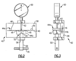
- Figure 2 illustrates an example bending test fixture 42 (apparatus) for deflecting the test coupon 40 as described above in the deflection step 24 of the method 20.
- the test coupon 40 generally occupies a test region.
- the bending test fixture 42 includes first and second supports 44a and 44b on opposed sides of the test region.
- the first support 44a includes a first pair of spaced-apart support points 46
- the second support 44b includes a second pair of spaced-apart support points 48 that are narrowly spaced relative to the first pair of spaced-apart support points 46.
- the first pair of spaced-apart support points 46 project from a frame 58.
- the spaced-apart support points 46 of the first support 44a contact the test coupon 40 near its ends, and the spaced-apart support points 48 of the second support 44b contact the test coupon 40 near its center.
- the spaced-apart support points 46 may be about 7.62 cm apart, and the spaced-apart support points 48 may be about 2.54 cm apart.
- the bending test fixture 42 is therefore adapted for 4-point bending.
- the bending test fixture 42 distributes the applied load over the area of the test coupon that is between the spaced-apart support points 48. Applying the load over an area of the test coupon avoids concentrating the load on a single point of the test coupon, which could lead to variation in the results of the test.
- a load shaft 50 is operably connected to the second support 44b for applying a load to the test coupon 40. It is to be understood that in other examples, the load shaft 50 may alternatively be operably connected to the first support 44a.
- the bending test fixture 42 includes an articulated joint 52 between the load shaft 50 and the second support 44b for distributing a load to the second support 44b. That is, there is rotational freedom between the second support 44b and the load shaft 50.
- the second support 44b includes a socket 54 and the end of the load shaft 50 includes a ball 56 that is received into the socket 54.
- the ball 56 is a semi-sphere.
- the second support 44 may include the ball 56 and the end of the load shaft 50 may include the socket 54.
- the socket 54 may have a V-shaped cross-section such that the sides of the ball 56 contact each side of the V-shape when the load is applied.
- the articulated joint 52 provides the benefit of evenly distributing the load between the spaced-apart support points 48 of the second support 44b to avoid concentrating too much of the load on one point and potentially negatively influencing the outcome of the test.
- the first and second supports 44a and 44b, and the load shaft 50 may generally be supported in the frame 58.
- the frame 58 may also support a gauge 60 having a probe 62 that extends near the test region to detect an amount of deflection of the test coupon 40.
- the gauge 60 is a dial indicator that indicates the amount of deflection.
- other types of gauges including electronic gauges, may be used.
- the bending test fixture 42 may also include a manual crank 70 operably connected with the load shaft 50 for applying a load to the test coupon 40.
- a user may apply a load using the manual crank 70 such that the bending test fixture 42 deflects the test coupon 40 to a desired amount that is equal to the calculated deflection value ⁇ .
- the user may apply only enough force to result in the desired amount of deflection by watching the gauge and turning the manual crank 70 slowly enough to ramp up the deflection to the desired amount.
- a user may utilize the bending test fixture 42 to test one or more test coupons 40 as an indication of whether a fatigue performance of one or more coated parts meets a specified level. That is, if the user applies an amount of deflection equal to the calculated deflection value ⁇ without the test coupon 40 cracking, the parts that were coated along with the test coupons 40 are expected to meet the specified level of fatigue performance. Thus, the test coupons 40 non-destructively verify the performance of the coated part.
Landscapes
- Chemical & Material Sciences (AREA)
- Health & Medical Sciences (AREA)
- Life Sciences & Earth Sciences (AREA)
- General Health & Medical Sciences (AREA)
- Analytical Chemistry (AREA)
- Biochemistry (AREA)
- Physics & Mathematics (AREA)
- General Physics & Mathematics (AREA)
- Immunology (AREA)
- Pathology (AREA)
- Engineering & Computer Science (AREA)
- Food Science & Technology (AREA)
- Medicinal Chemistry (AREA)
- Investigating Strength Of Materials By Application Of Mechanical Stress (AREA)
- Length Measuring Devices With Unspecified Measuring Means (AREA)
Applications Claiming Priority (1)
| Application Number | Priority Date | Filing Date | Title |
|---|---|---|---|
| US12/336,833 US8177953B2 (en) | 2008-12-17 | 2008-12-17 | Method and apparatus for evaluation of coated parts |
Publications (3)
| Publication Number | Publication Date |
|---|---|
| EP2199775A2 true EP2199775A2 (de) | 2010-06-23 |
| EP2199775A3 EP2199775A3 (de) | 2014-10-22 |
| EP2199775B1 EP2199775B1 (de) | 2021-08-25 |
Family
ID=42035580
Family Applications (1)
| Application Number | Title | Priority Date | Filing Date |
|---|---|---|---|
| EP09252816.5A Active EP2199775B1 (de) | 2008-12-17 | 2009-12-17 | Verfahren zur Beurteilung von beschichteten Teilen |
Country Status (2)
| Country | Link |
|---|---|
| US (2) | US8177953B2 (de) |
| EP (1) | EP2199775B1 (de) |
Cited By (2)
| Publication number | Priority date | Publication date | Assignee | Title |
|---|---|---|---|---|
| CN104634654A (zh) * | 2013-11-14 | 2015-05-20 | 珠海格力电器股份有限公司 | 测试辅助工装 |
| CN117949277A (zh) * | 2024-03-25 | 2024-04-30 | 中国航发四川燃气涡轮研究院 | 一种用于轮盘周向高应力部位的缺陷预制结构及方法 |
Families Citing this family (17)
| Publication number | Priority date | Publication date | Assignee | Title |
|---|---|---|---|---|
| US8177953B2 (en) * | 2008-12-17 | 2012-05-15 | Hamilton Sundstrand Corporation | Method and apparatus for evaluation of coated parts |
| WO2011071865A2 (en) * | 2009-12-08 | 2011-06-16 | National Oilwell Varco, L.P. | Corrosion testing apparatus and methods |
| US8950270B2 (en) | 2011-03-01 | 2015-02-10 | Textron Innovatons Inc. | Short beam shear test fixture |
| RU2499244C1 (ru) * | 2012-04-10 | 2013-11-20 | Федеральное государственное бюджетное образовательное учреждение высшего профессионального образования "Казанский национальный исследовательский технический университет им. А.Н. Туполева-КАИ" (КНИТУ-КАИ) | Способ определения остаточных напряжений и энергетических характеристик газотермических покрытий |
| US9176039B2 (en) * | 2013-02-28 | 2015-11-03 | The Boeing Company | Method and systems for determining hydrogen embrittlement |
| JP6190965B2 (ja) * | 2013-12-20 | 2017-08-30 | ティッセンクルップ スチール ヨーロッパ アクチェンゲゼルシャフトThyssenKrupp Steel Europe AG | 被覆された平板製品を曲げることによってその摩耗性を判定する方法および装置 |
| GB2524479B (en) * | 2014-03-21 | 2016-02-17 | Rolls Royce Plc | Testing rig |
| RU2582229C1 (ru) * | 2014-12-29 | 2016-04-20 | Общество с ограниченной ответственностью Научно-исследовательское производственное предприятие "ВАЛЬМА" | Установка для испытаний образцов металла сварных и бесшовных труб |
| US10060840B2 (en) * | 2015-07-21 | 2018-08-28 | Goodrich Corporation | Methods of determining strain limits and designing devices based on strain limits |
| CN105784470A (zh) * | 2016-04-10 | 2016-07-20 | 济南天辰试验机制造有限公司 | 一种180°弯曲试验夹具 |
| US10371611B2 (en) * | 2017-01-12 | 2019-08-06 | Rolls-Royce North American Technologies Inc. | Material testing system and method of use |
| CN107917844A (zh) * | 2018-01-16 | 2018-04-17 | 天津工业大学 | 一种复合材料三点、四点弯曲疲劳通用试验夹具 |
| CN112041661A (zh) * | 2018-03-20 | 2020-12-04 | 爱勒斯轧制品公司 | 通用条带摩擦学模拟器 |
| US10774439B2 (en) * | 2018-11-14 | 2020-09-15 | The Boeing Company | Methods of monitoring a plating bath |
| JP7180572B2 (ja) * | 2019-09-17 | 2022-11-30 | 株式会社島津製作所 | 材料試験機 |
| CN113109134A (zh) * | 2021-04-26 | 2021-07-13 | 东风本田发动机有限公司 | 弹性模量测量装置 |
| CN114878301B (zh) * | 2022-04-15 | 2024-12-31 | 广东省科学院新材料研究所 | 一种涂层长时高温弯曲实验装置及方法 |
Family Cites Families (30)
| Publication number | Priority date | Publication date | Assignee | Title |
|---|---|---|---|---|
| US2670624A (en) * | 1950-04-04 | 1954-03-02 | Standard Oil Co | Apparatus for measurement of low rate deformability |
| US3803485A (en) * | 1970-02-16 | 1974-04-09 | Battelle Development Corp | Indicating coating for locating fatigue cracks |
| US3636758A (en) * | 1970-04-20 | 1972-01-25 | Aluminum Co Of America | Bend-stretch apparatus for testing formable material |
| DE2428992A1 (de) * | 1974-06-15 | 1976-01-02 | Metzeler Gummitechnik | Verfahren zum zerstoerungsfreien pruefen von elastischen und/oder visco-elastischen bauteilen mittels holografischer interferometrie |
| US4160702A (en) * | 1978-04-21 | 1979-07-10 | General Motors Corporation | Electrochemical measurement of fatigue damage |
| US4381663A (en) * | 1981-03-06 | 1983-05-03 | Washington University | Fluid oscillation materials testing apparatus and methods |
| US4433582A (en) * | 1981-05-26 | 1984-02-28 | Conoco Inc. | Damping device for use with acoustic information generation machines |
| US4413510A (en) * | 1981-11-19 | 1983-11-08 | Rca Corporation | Coating adhesion testing |
| US4610157A (en) * | 1984-12-11 | 1986-09-09 | United Technologies Corporation | Surface penetrant inspection test piece having varying thickness plating |
| US4764680A (en) * | 1987-04-14 | 1988-08-16 | United Technologies Corporation | Method of and arrangement for testing cylindrical objects for shape deviations |
| US4730498A (en) * | 1987-06-01 | 1988-03-15 | Rheometrics, Inc. | Fixture for holding a bending test specimen |
| US4941359A (en) * | 1989-02-02 | 1990-07-17 | The United States Of America As Represented By The Secretary Of The Army | Articulating flexure test fixture |
| US5111676A (en) * | 1990-10-04 | 1992-05-12 | United Technologies Corporation | Tool for selectively bending the trailing edge tab of a helicopter blade while simultaneously measuring the true degree of tab bending |
| US5142905A (en) * | 1991-02-08 | 1992-09-01 | United Technologies Corporation | Overlapped test specimen fixture |
| FR2675578B1 (fr) * | 1991-04-22 | 1993-08-20 | Aerospatiale | Dispositif d'essais d'eprouvettes en flexion dans un milieu ambiant cryogene. |
| US5199305A (en) * | 1991-10-21 | 1993-04-06 | The United States Of America As Represented By The Administrator Of National Aeronautics And Space Administration | Method and apparatus for measuring the strain developed in a coated surface |
| US5187987A (en) * | 1991-11-19 | 1993-02-23 | The Pennsylvania Research Corporation | Bending beam creep test device with piston having a gas bearing |
| US5500535A (en) * | 1995-03-07 | 1996-03-19 | Molecular Imaging Corporation | Stress cell for a scanning probe microscope |
| US5847283A (en) * | 1996-07-03 | 1998-12-08 | Massachusetts Institute Of Technology | Method and apparatus for the evaluation of a depth profile of thermo-mechanical properties of layered and graded materials and coatings |
| DE19637808C1 (de) * | 1996-09-17 | 1997-12-18 | Honeywell Ag | Vorrichtung zur Messung der Biegesteifigkeit von bewegtem blattförmigem Material |
| US5837882A (en) * | 1997-06-05 | 1998-11-17 | Ntn Corporation | Stationary element rolling contact fatigue tester |
| US6050138A (en) * | 1997-10-22 | 2000-04-18 | Exponent, Inc. | System and method for performing bulge testing of films, coatings and/or layers |
| US6662631B2 (en) * | 1998-08-28 | 2003-12-16 | Interuniversitair Microelektronica Centrum | Method and apparatus for characterization of porous films |
| US7106055B2 (en) * | 2003-11-14 | 2006-09-12 | Jentek Sensors, Inc. | Fabrication of samples having predetermined material conditions |
| US7201064B2 (en) * | 2005-03-25 | 2007-04-10 | Huber Engineered Woods Llc | Panel bending machine |
| TWI300124B (en) * | 2005-10-03 | 2008-08-21 | Ind Tech Res Inst | Method and system for inspecting flexible device |
| US7897265B2 (en) * | 2006-01-26 | 2011-03-01 | Hamilton Sundstrand Corporation | Low cost, environmentally favorable, chromium plate replacement coating for improved wear performance |
| US7464606B2 (en) * | 2006-04-18 | 2008-12-16 | Agency For Science, Technology And Research | Bend testing apparatus and method of carrying out the same |
| US7546775B2 (en) * | 2007-06-04 | 2009-06-16 | Bose Corporation | Bend tool |
| US8177953B2 (en) * | 2008-12-17 | 2012-05-15 | Hamilton Sundstrand Corporation | Method and apparatus for evaluation of coated parts |
-
2008
- 2008-12-17 US US12/336,833 patent/US8177953B2/en active Active
-
2009
- 2009-12-17 EP EP09252816.5A patent/EP2199775B1/de active Active
-
2012
- 2012-04-03 US US13/438,384 patent/US8443678B2/en active Active
Non-Patent Citations (1)
| Title |
|---|
| None |
Cited By (3)
| Publication number | Priority date | Publication date | Assignee | Title |
|---|---|---|---|---|
| CN104634654A (zh) * | 2013-11-14 | 2015-05-20 | 珠海格力电器股份有限公司 | 测试辅助工装 |
| CN117949277A (zh) * | 2024-03-25 | 2024-04-30 | 中国航发四川燃气涡轮研究院 | 一种用于轮盘周向高应力部位的缺陷预制结构及方法 |
| CN117949277B (zh) * | 2024-03-25 | 2024-06-04 | 中国航发四川燃气涡轮研究院 | 一种用于轮盘周向高应力部位的缺陷预制结构及方法 |
Also Published As
| Publication number | Publication date |
|---|---|
| US8177953B2 (en) | 2012-05-15 |
| EP2199775A3 (de) | 2014-10-22 |
| US20100147694A1 (en) | 2010-06-17 |
| US8443678B2 (en) | 2013-05-21 |
| EP2199775B1 (de) | 2021-08-25 |
| US20120186358A1 (en) | 2012-07-26 |
Similar Documents
| Publication | Publication Date | Title |
|---|---|---|
| EP2199775B1 (de) | Verfahren zur Beurteilung von beschichteten Teilen | |
| CN102507355B (zh) | 一种金属薄膜镀层结合质量检测方法 | |
| EP1836473B1 (de) | Auswertungsverfahren für das eigenspannungsbestimmungsverfahren unter verwendung des dauereindruckverfahrens | |
| US8082799B2 (en) | Method of forecasting the lifetime of structural parts | |
| Zhao et al. | Measuring elastoplastic properties of thin films on an elastic substrate using sharp indentation | |
| Razin et al. | Detecting and estimating the extent of automotive coating delamination and damage indexes after stone chipping using electrochemical impedance spectroscopy | |
| Menčík | Determination of mechanical properties by instrumented indentation | |
| Lim et al. | Continuous fatigue crack length estimation for aluminum 6061-T6 plates with a notch | |
| CN109520828B (zh) | 薄膜的弹性模量测试方法 | |
| Caprili et al. | Evaluation of mechanical characteristics of steel bars by non-destructive Vickers micro-hardness tests | |
| US7159470B2 (en) | Systems and methods of measuring residual stress in metallic materials | |
| Panerai et al. | Advanced strain-based approaches for monitoring crack tip position in adhesively bonded joints subjected to mixed mode fatigue loading | |
| Panerai et al. | Distributed backface strain sensing of composite adhesively bonded joints under mode II fatigue loading | |
| JP4858773B2 (ja) | ナノインデンテーション試験の検証方法 | |
| CN118670866B (zh) | 基于断裂截面特性的金属材料小尺寸断裂韧性测试方法 | |
| RU2108560C1 (ru) | Способ определения остаточного ресурса конструкции | |
| Deflorian et al. | Defect dimension evaluation in organic coated galvanized steel by electrochemical impedance spectroscopy | |
| Panerai et al. | Monitoring crack tip position in adhesively bonded joints under mixed I+ II mode loading | |
| RU2393454C2 (ru) | Способ определения вязкости металла | |
| KR101685507B1 (ko) | 계면접합력 평가방법 | |
| RU2032163C1 (ru) | Способ диагностики металлоконструкций сосудов и аппаратов давления и определения их остаточного ресурса | |
| Albagachiev et al. | Microhardness and tribological characteristics of coatings | |
| RU2845832C1 (ru) | Способ определения характеристики трещиностойкости хрупких материалов и покрытий | |
| RU2691751C1 (ru) | Способ определения предельного состояния материала магистральных газопроводов | |
| RU2846774C1 (ru) | Способ определения напряжённо-деформированного состояния металлоконструкций с учётом толщины лакокрасочного покрытия |
Legal Events
| Date | Code | Title | Description |
|---|---|---|---|
| PUAI | Public reference made under article 153(3) epc to a published international application that has entered the european phase |
Free format text: ORIGINAL CODE: 0009012 |
|
| AK | Designated contracting states |
Kind code of ref document: A2 Designated state(s): AT BE BG CH CY CZ DE DK EE ES FI FR GB GR HR HU IE IS IT LI LT LU LV MC MK MT NL NO PL PT RO SE SI SK SM TR |
|
| AX | Request for extension of the european patent |
Extension state: AL BA RS |
|
| RIC1 | Information provided on ipc code assigned before grant |
Ipc: G01N 3/20 20060101ALI20140416BHEP Ipc: G01N 3/04 20060101AFI20140416BHEP Ipc: G01N 19/04 20060101ALI20140416BHEP |
|
| PUAL | Search report despatched |
Free format text: ORIGINAL CODE: 0009013 |
|
| AK | Designated contracting states |
Kind code of ref document: A3 Designated state(s): AT BE BG CH CY CZ DE DK EE ES FI FR GB GR HR HU IE IS IT LI LT LU LV MC MK MT NL NO PL PT RO SE SI SK SM TR |
|
| AX | Request for extension of the european patent |
Extension state: AL BA RS |
|
| RIC1 | Information provided on ipc code assigned before grant |
Ipc: G01N 3/20 20060101ALI20140916BHEP Ipc: G01N 19/04 20060101ALI20140916BHEP Ipc: G01N 3/04 20060101AFI20140916BHEP |
|
| 17P | Request for examination filed |
Effective date: 20150414 |
|
| RBV | Designated contracting states (corrected) |
Designated state(s): AT BE BG CH CY CZ DE DK EE ES FI FR GB GR HR HU IE IS IT LI LT LU LV MC MK MT NL NO PL PT RO SE SI SK SM TR |
|
| STAA | Information on the status of an ep patent application or granted ep patent |
Free format text: STATUS: EXAMINATION IS IN PROGRESS |
|
| 17Q | First examination report despatched |
Effective date: 20170215 |
|
| GRAP | Despatch of communication of intention to grant a patent |
Free format text: ORIGINAL CODE: EPIDOSNIGR1 |
|
| STAA | Information on the status of an ep patent application or granted ep patent |
Free format text: STATUS: GRANT OF PATENT IS INTENDED |
|
| INTG | Intention to grant announced |
Effective date: 20210416 |
|
| RAP3 | Party data changed (applicant data changed or rights of an application transferred) |
Owner name: HAMILTON SUNDSTRAND CORPORATION |
|
| GRAS | Grant fee paid |
Free format text: ORIGINAL CODE: EPIDOSNIGR3 |
|
| GRAA | (expected) grant |
Free format text: ORIGINAL CODE: 0009210 |
|
| STAA | Information on the status of an ep patent application or granted ep patent |
Free format text: STATUS: THE PATENT HAS BEEN GRANTED |
|
| AK | Designated contracting states |
Kind code of ref document: B1 Designated state(s): AT BE BG CH CY CZ DE DK EE ES FI FR GB GR HR HU IE IS IT LI LT LU LV MC MK MT NL NO PL PT RO SE SI SK SM TR |
|
| REG | Reference to a national code |
Ref country code: GB Ref legal event code: FG4D |
|
| REG | Reference to a national code |
Ref country code: CH Ref legal event code: EP |
|
| REG | Reference to a national code |
Ref country code: DE Ref legal event code: R096 Ref document number: 602009063977 Country of ref document: DE |
|
| REG | Reference to a national code |
Ref country code: IE Ref legal event code: FG4D Ref country code: AT Ref legal event code: REF Ref document number: 1424282 Country of ref document: AT Kind code of ref document: T Effective date: 20210915 |
|
| REG | Reference to a national code |
Ref country code: LT Ref legal event code: MG9D |
|
| REG | Reference to a national code |
Ref country code: NL Ref legal event code: MP Effective date: 20210825 |
|
| REG | Reference to a national code |
Ref country code: AT Ref legal event code: MK05 Ref document number: 1424282 Country of ref document: AT Kind code of ref document: T Effective date: 20210825 |
|
| PG25 | Lapsed in a contracting state [announced via postgrant information from national office to epo] |
Ref country code: PT Free format text: LAPSE BECAUSE OF FAILURE TO SUBMIT A TRANSLATION OF THE DESCRIPTION OR TO PAY THE FEE WITHIN THE PRESCRIBED TIME-LIMIT Effective date: 20211227 Ref country code: NO Free format text: LAPSE BECAUSE OF FAILURE TO SUBMIT A TRANSLATION OF THE DESCRIPTION OR TO PAY THE FEE WITHIN THE PRESCRIBED TIME-LIMIT Effective date: 20211125 Ref country code: FI Free format text: LAPSE BECAUSE OF FAILURE TO SUBMIT A TRANSLATION OF THE DESCRIPTION OR TO PAY THE FEE WITHIN THE PRESCRIBED TIME-LIMIT Effective date: 20210825 Ref country code: ES Free format text: LAPSE BECAUSE OF FAILURE TO SUBMIT A TRANSLATION OF THE DESCRIPTION OR TO PAY THE FEE WITHIN THE PRESCRIBED TIME-LIMIT Effective date: 20210825 Ref country code: BG Free format text: LAPSE BECAUSE OF FAILURE TO SUBMIT A TRANSLATION OF THE DESCRIPTION OR TO PAY THE FEE WITHIN THE PRESCRIBED TIME-LIMIT Effective date: 20211125 Ref country code: AT Free format text: LAPSE BECAUSE OF FAILURE TO SUBMIT A TRANSLATION OF THE DESCRIPTION OR TO PAY THE FEE WITHIN THE PRESCRIBED TIME-LIMIT Effective date: 20210825 Ref country code: LT Free format text: LAPSE BECAUSE OF FAILURE TO SUBMIT A TRANSLATION OF THE DESCRIPTION OR TO PAY THE FEE WITHIN THE PRESCRIBED TIME-LIMIT Effective date: 20210825 Ref country code: HR Free format text: LAPSE BECAUSE OF FAILURE TO SUBMIT A TRANSLATION OF THE DESCRIPTION OR TO PAY THE FEE WITHIN THE PRESCRIBED TIME-LIMIT Effective date: 20210825 Ref country code: SE Free format text: LAPSE BECAUSE OF FAILURE TO SUBMIT A TRANSLATION OF THE DESCRIPTION OR TO PAY THE FEE WITHIN THE PRESCRIBED TIME-LIMIT Effective date: 20210825 |
|
| PG25 | Lapsed in a contracting state [announced via postgrant information from national office to epo] |
Ref country code: PL Free format text: LAPSE BECAUSE OF FAILURE TO SUBMIT A TRANSLATION OF THE DESCRIPTION OR TO PAY THE FEE WITHIN THE PRESCRIBED TIME-LIMIT Effective date: 20210825 Ref country code: LV Free format text: LAPSE BECAUSE OF FAILURE TO SUBMIT A TRANSLATION OF THE DESCRIPTION OR TO PAY THE FEE WITHIN THE PRESCRIBED TIME-LIMIT Effective date: 20210825 Ref country code: GR Free format text: LAPSE BECAUSE OF FAILURE TO SUBMIT A TRANSLATION OF THE DESCRIPTION OR TO PAY THE FEE WITHIN THE PRESCRIBED TIME-LIMIT Effective date: 20211126 |
|
| PG25 | Lapsed in a contracting state [announced via postgrant information from national office to epo] |
Ref country code: NL Free format text: LAPSE BECAUSE OF FAILURE TO SUBMIT A TRANSLATION OF THE DESCRIPTION OR TO PAY THE FEE WITHIN THE PRESCRIBED TIME-LIMIT Effective date: 20210825 |
|
| PG25 | Lapsed in a contracting state [announced via postgrant information from national office to epo] |
Ref country code: DK Free format text: LAPSE BECAUSE OF FAILURE TO SUBMIT A TRANSLATION OF THE DESCRIPTION OR TO PAY THE FEE WITHIN THE PRESCRIBED TIME-LIMIT Effective date: 20210825 |
|
| REG | Reference to a national code |
Ref country code: DE Ref legal event code: R097 Ref document number: 602009063977 Country of ref document: DE |
|
| PG25 | Lapsed in a contracting state [announced via postgrant information from national office to epo] |
Ref country code: SM Free format text: LAPSE BECAUSE OF FAILURE TO SUBMIT A TRANSLATION OF THE DESCRIPTION OR TO PAY THE FEE WITHIN THE PRESCRIBED TIME-LIMIT Effective date: 20210825 Ref country code: SK Free format text: LAPSE BECAUSE OF FAILURE TO SUBMIT A TRANSLATION OF THE DESCRIPTION OR TO PAY THE FEE WITHIN THE PRESCRIBED TIME-LIMIT Effective date: 20210825 Ref country code: RO Free format text: LAPSE BECAUSE OF FAILURE TO SUBMIT A TRANSLATION OF THE DESCRIPTION OR TO PAY THE FEE WITHIN THE PRESCRIBED TIME-LIMIT Effective date: 20210825 Ref country code: EE Free format text: LAPSE BECAUSE OF FAILURE TO SUBMIT A TRANSLATION OF THE DESCRIPTION OR TO PAY THE FEE WITHIN THE PRESCRIBED TIME-LIMIT Effective date: 20210825 Ref country code: CZ Free format text: LAPSE BECAUSE OF FAILURE TO SUBMIT A TRANSLATION OF THE DESCRIPTION OR TO PAY THE FEE WITHIN THE PRESCRIBED TIME-LIMIT Effective date: 20210825 |
|
| PLBE | No opposition filed within time limit |
Free format text: ORIGINAL CODE: 0009261 |
|
| STAA | Information on the status of an ep patent application or granted ep patent |
Free format text: STATUS: NO OPPOSITION FILED WITHIN TIME LIMIT |
|
| PG25 | Lapsed in a contracting state [announced via postgrant information from national office to epo] |
Ref country code: MC Free format text: LAPSE BECAUSE OF FAILURE TO SUBMIT A TRANSLATION OF THE DESCRIPTION OR TO PAY THE FEE WITHIN THE PRESCRIBED TIME-LIMIT Effective date: 20210825 Ref country code: IT Free format text: LAPSE BECAUSE OF FAILURE TO SUBMIT A TRANSLATION OF THE DESCRIPTION OR TO PAY THE FEE WITHIN THE PRESCRIBED TIME-LIMIT Effective date: 20210825 |
|
| REG | Reference to a national code |
Ref country code: CH Ref legal event code: PL |
|
| 26N | No opposition filed |
Effective date: 20220527 |
|
| PG25 | Lapsed in a contracting state [announced via postgrant information from national office to epo] |
Ref country code: SI Free format text: LAPSE BECAUSE OF FAILURE TO SUBMIT A TRANSLATION OF THE DESCRIPTION OR TO PAY THE FEE WITHIN THE PRESCRIBED TIME-LIMIT Effective date: 20210825 |
|
| REG | Reference to a national code |
Ref country code: BE Ref legal event code: MM Effective date: 20211231 |
|
| PG25 | Lapsed in a contracting state [announced via postgrant information from national office to epo] |
Ref country code: LU Free format text: LAPSE BECAUSE OF NON-PAYMENT OF DUE FEES Effective date: 20211217 Ref country code: IE Free format text: LAPSE BECAUSE OF NON-PAYMENT OF DUE FEES Effective date: 20211217 |
|
| PG25 | Lapsed in a contracting state [announced via postgrant information from national office to epo] |
Ref country code: BE Free format text: LAPSE BECAUSE OF NON-PAYMENT OF DUE FEES Effective date: 20211231 |
|
| PG25 | Lapsed in a contracting state [announced via postgrant information from national office to epo] |
Ref country code: LI Free format text: LAPSE BECAUSE OF NON-PAYMENT OF DUE FEES Effective date: 20211231 Ref country code: CH Free format text: LAPSE BECAUSE OF NON-PAYMENT OF DUE FEES Effective date: 20211231 |
|
| PG25 | Lapsed in a contracting state [announced via postgrant information from national office to epo] |
Ref country code: HU Free format text: LAPSE BECAUSE OF FAILURE TO SUBMIT A TRANSLATION OF THE DESCRIPTION OR TO PAY THE FEE WITHIN THE PRESCRIBED TIME-LIMIT; INVALID AB INITIO Effective date: 20091217 Ref country code: CY Free format text: LAPSE BECAUSE OF FAILURE TO SUBMIT A TRANSLATION OF THE DESCRIPTION OR TO PAY THE FEE WITHIN THE PRESCRIBED TIME-LIMIT Effective date: 20210825 |
|
| P01 | Opt-out of the competence of the unified patent court (upc) registered |
Effective date: 20230522 |
|
| PG25 | Lapsed in a contracting state [announced via postgrant information from national office to epo] |
Ref country code: MK Free format text: LAPSE BECAUSE OF FAILURE TO SUBMIT A TRANSLATION OF THE DESCRIPTION OR TO PAY THE FEE WITHIN THE PRESCRIBED TIME-LIMIT Effective date: 20210825 |
|
| PG25 | Lapsed in a contracting state [announced via postgrant information from national office to epo] |
Ref country code: TR Free format text: LAPSE BECAUSE OF FAILURE TO SUBMIT A TRANSLATION OF THE DESCRIPTION OR TO PAY THE FEE WITHIN THE PRESCRIBED TIME-LIMIT Effective date: 20210825 |
|
| PG25 | Lapsed in a contracting state [announced via postgrant information from national office to epo] |
Ref country code: MT Free format text: LAPSE BECAUSE OF FAILURE TO SUBMIT A TRANSLATION OF THE DESCRIPTION OR TO PAY THE FEE WITHIN THE PRESCRIBED TIME-LIMIT Effective date: 20210825 |
|
| PGFP | Annual fee paid to national office [announced via postgrant information from national office to epo] |
Ref country code: DE Payment date: 20251126 Year of fee payment: 17 |
|
| PGFP | Annual fee paid to national office [announced via postgrant information from national office to epo] |
Ref country code: GB Payment date: 20251119 Year of fee payment: 17 |
|
| PGFP | Annual fee paid to national office [announced via postgrant information from national office to epo] |
Ref country code: FR Payment date: 20251119 Year of fee payment: 17 |